
Translation of the Original Operating Manual
ID 130/22
GBR

2/33

3/33
Copyright
Copyright by
Kärcher Industrial Vacuuming GmbH
Robert-Bosch-Straße 4-8
73550 Waldstetten
GERMANY

4/33
1 Safety Instructions ............................................................................................................... 7
1.1 Terms ............................................................................................................................. 7
1.1.1 Operation ..................................................................................................................... 7
1.1.2 Maintenance................................................................................................................. 7
1.1.3 Qualified Staff ............................................................................................................... 7
1.2 Symbols .......................................................................................................................... 7
1.3 General safety information ................................................................................................. 9
2 Delivery, internal transportation, unpacking......................................................................... 10
2.1 Delivery ......................................................................................................................... 10
2.2 Internal transport............................................................................................................. 10
2.2.1 Dimensions and weight ................................................................................................ 10
2.3 Unpacking ..................................................................................................................... 10
2.4 Packaging material.......................................................................................................... 11
2.5 Storage conditions .......................................................................................................... 11
2.5.1 Information for storage ................................................................................................. 11
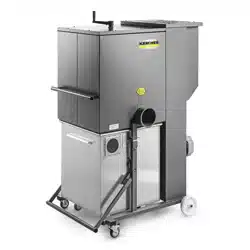
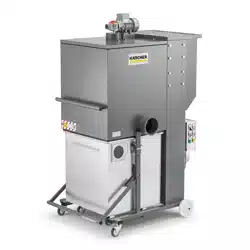
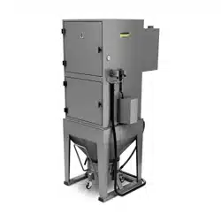
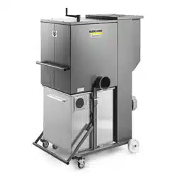
3 Appliance description ........................................................................................................ 12
3.1 Intended Use.................................................................................................................. 12
3.1.1 Dust class "M"............................................................................................................. 12
3.2 Non-Intended Use ........................................................................................................... 12
3.2.1 Dust class "M"............................................................................................................. 12
4 Layout and function ........................................................................................................... 13
4.1 Main dimensions............................................................................................................. 13
4.2 Technical Data ............................................................................................................... 13
5 Main components............................................................................................................... 14
5.1 Chart "Raw air/clean air flow"............................................................................................ 14
6 Initiation ............................................................................................................................ 15
6.1 Initial commissioning ....................................................................................................... 15
6.2 Connection to an extraction source (e.g. processing machine) ............................................... 15
6.3 Assembly Instruction Pipes............................................................................................... 16
6.4 Assembly Instructions Hose.............................................................................................. 16
6.5 Assembly Instruction Pipes............................................................................................... 17
6.6 Assembly Instructions Hose.............................................................................................. 17
7 Operation .......................................................................................................................... 19
7.1 Minimum air volume flow control ..................................................................................... 19
7.2 Cleaning of the filter cartridge ......................................................................................... 19
7.3 Emptying the collection container ...................................................................................... 20
8 Troubleshooting and fault elimination ................................................................................. 21
8.1 Safety instructions........................................................................................................... 21
8.2 Initial fault elimination measures........................................................................................ 22
9 Maintenance/Repair............................................................................................................ 23
9.1 Maintenance regulations .................................................................................................. 23
9.2 Maintenance intervals table .............................................................................................. 23
9.3 Replacing the filter cartridge ........................................................................................... 24
9.4 Procedure when replacing the filter cartridge.................................................................... 24
9.5 Circuit diagram ............................................................................................................... 25

5/33
10 Decommissioning, storage ................................................................................................. 26
11 Disposal ............................................................................................................................ 27
12 Spare Parts List ................................................................................................................. 28
12.1 Components .................................................................................................................. 28
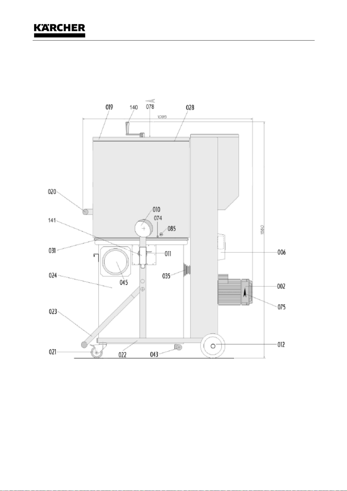
12.1.1 Side view "intake socket closed"................................................................................. 28
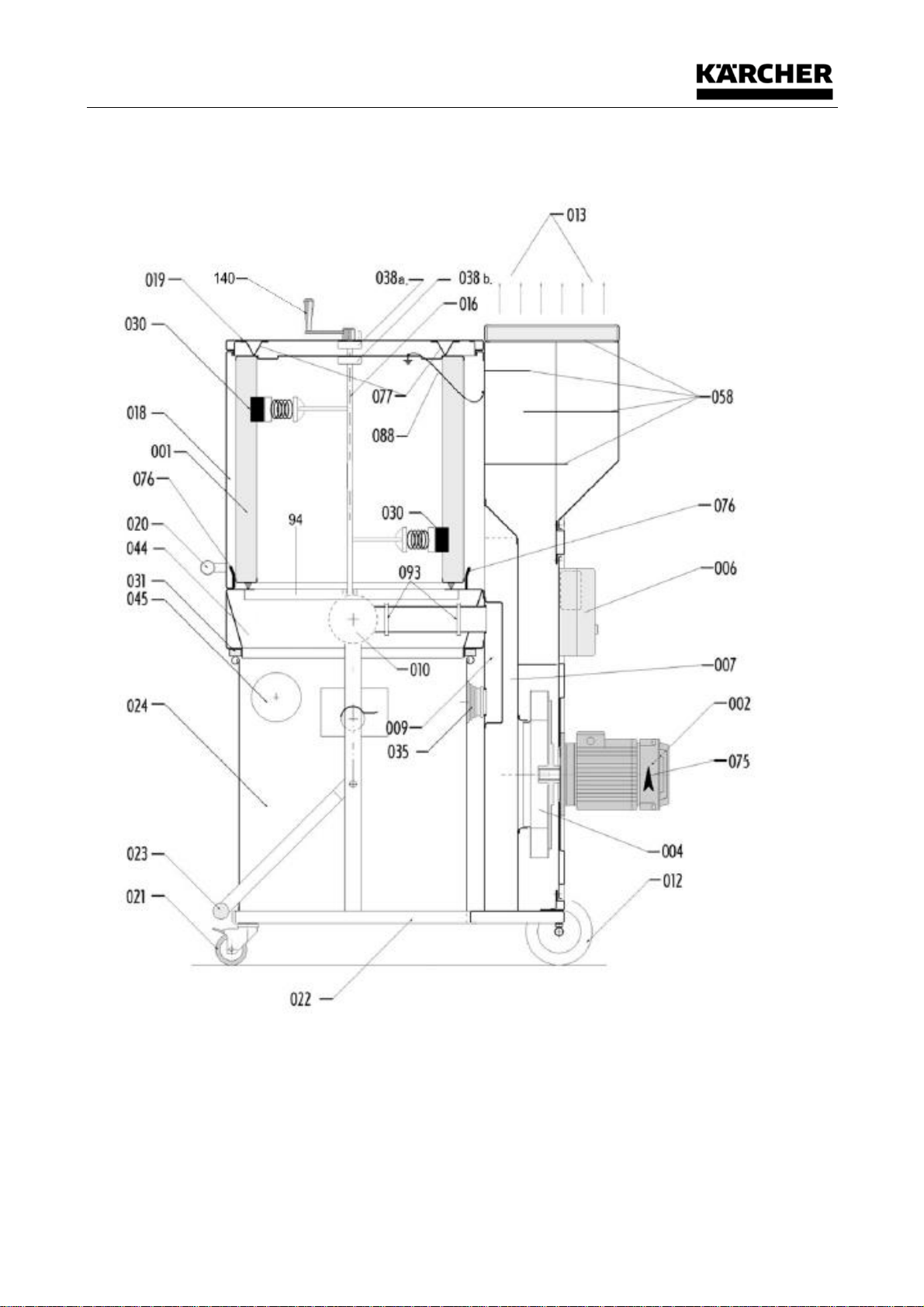
12.1.2 Side view "intake socket cross-section" ....................................................................... 29
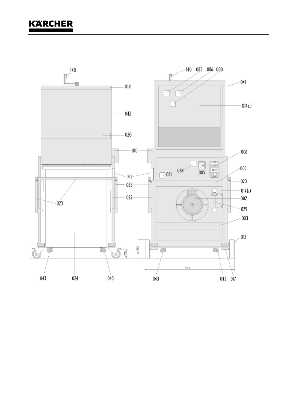
12.1.3 Front view "filter housing, transport grip" and view "Motor, filter chamber cover" ................ 30
12.1.4 Details of motor protection switch (main switch) ............................................................ 31
12.1.5 Detail differential pressure switch ............................................................................... 31
12.1.6 Detail plug 16A (5-pin with phase inverter) ................................................................... 31
13 EEC-Declaration of Conformity ........................................................................................... 33

Safety Instructions
6/33
Safety Instructions
7/33
1 Safety Instructions
1.1 Terms
1.1.1 Operation
includes installation, initiation (placing at disposal for usage), operation (handling, connection,
disconnection, etc.)
1.1.2 Maintenance
includes control and attendance (inspections, revisions), maintenance and repair (detection of errors
and their elimination).
1.1.3 Qualified Staff
are employees authorised by the person responsible for the security of the installation to carry out
the operations required in each case and who are able to recognise and avoid possible dangers by
reason of their training, experience and instructions as well as their knowledge of relevant norms,
prescriptions, accident-prevention rules and working conditions.
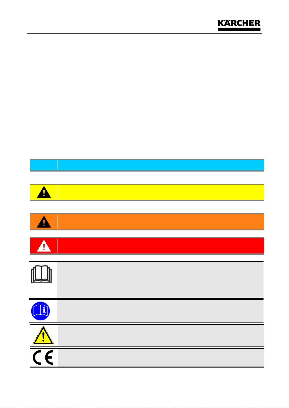
1.2 Symbols
NOTICE
Denotes information that does not relate to personal injuries.
This information contains additional directions or general hints.
CAUTION
Dangerous situation, which could result in minor to moderate injury if it is not avoided.
This information must be regarded strictly to avoid damages to the installation or environment!
WARNING
Dangerous situation, which could result in serious injury or death if it is not avoided.
DANGER
Dangerous situation, which will definitely result in serious injury or death if it is not avoided.
Significance of the Operating Manual
This Operating Manual is part of the supplied product.
The Operating Manual remains valid throughout the product's lifetime, provided that no
technical changes are made.
If the product is sold, the Operating Manual must be handed over to the next owner or user.
This information must be read before first commissioning.
WARNING - Read the instructions before using the machine
CE marking
The CE marking means "Communautés Européennes". It is the external symbol which states
Safety Instructions
8/33
that a product fulfils the requirements imposed on the manufacturer by the European
Community.
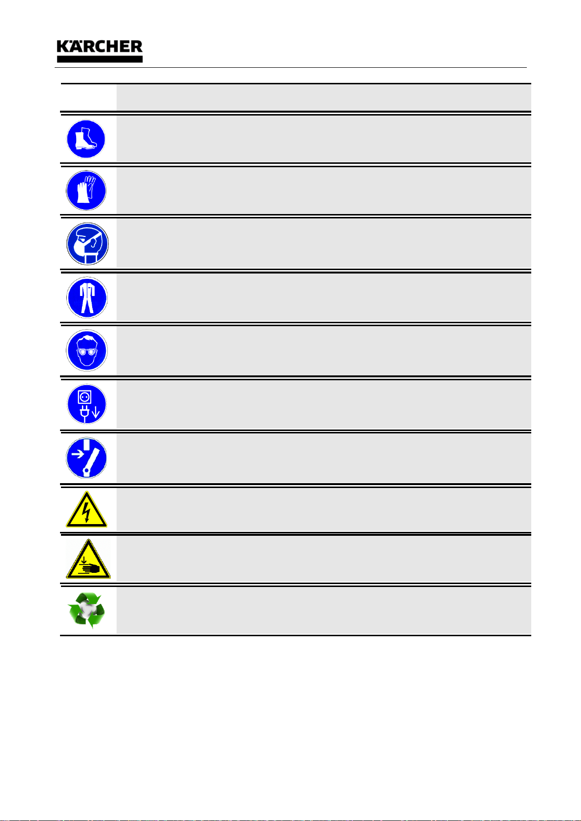
Only use with safety shoes (acc. to EN ISO 20345)
Only use with work gloves
Respiratory protection (EN 149:2001)
Use protective clothing (acc. to EN 13982-1)
Use protective glasses (acc. to DIN EN 166 1349-BT)
Before starting work remove the plug from the wall socket!
Disconnect before starting work
While operating electrical machines, certain parts of them are inevitable alive dangerously or
under mechanical stress.
Hand injury warning sign!
Recycling symbol
This information must be observed in order to preserve the environment!
Safety Instructions
9/33
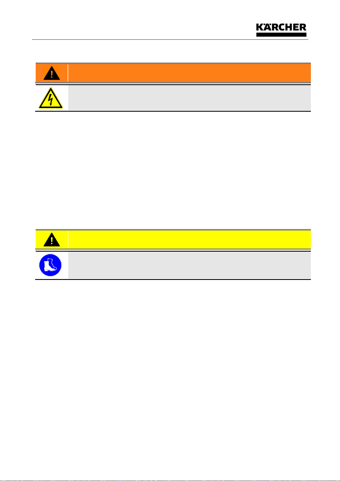
1.3 General safety information
WARNING
While operating electrical machines, certain parts of them are inevitable alive dangerously or
under mechanical stress.
Due to their electrical and mechanical functional properties, machines can cause severe injuries
and damage to property. This particularly applies in the event of incorrect use, operation or
maintenance, or in the event of unauthorized interventions!
All electrical work must be performed by a qualified electrician. All mechanical work must be carried
out according to instructions (see Maintenance / Repair). The device may be operated only by
qualified personnel who have read and understood the operating instructions.
The operator must be provided with information, instructions and training on the materials to be
absorbed, including a secure procedure for removal of the absorbed material, before use.
All notes and data on the machines must be observed!
Faultless and safe use of this machine includes correct transport and storage, as well as operation
in accordance with regulations and careful maintenance!
This device is not intended for being used by persons (including) with limited physical, sensory or
mental skills or lack of experience and/or lack of knowledge except if they are supervised by a
person responsible for their safety or were instructed in how to use the device by this person.
Children should be supervised to ensure that they do not play with the device.
• Operation of the device is only permitted on underground sloping no more than 10° and with
sufficient load-bearing capacity.
CAUTION
Only use with safety shoes (acc. to EN ISO 20345)
• Do not place any limbs between parts to be joined during assembly of the machine parts. When
moving the parts, pull limbs from tightening spaces in time.
• Make sure that the power supply cord is not damaged by being run over, crushed, tugged etc..
Stop the industrial vacuum cleaner immediately if necessary!
• The power supply cord must be regularly inspected for signs of damage or ageing!
• Connectors of power supply cords must at least be splash-proof!
• Starting without a filter or with a damaged filter is not allowed
The suction device must not be operated if wear is detected on fasteners or mounting brackets.
Please arrange for a service immediately, or send the industrial vacuum cleaner for repair to:
Kärcher Industrial Vacuuming GmbH
Abt. Service
Robert-Bosch-Straße 4-8
73550 Waldstetten
Tel: ++49-7171-94888-23
Delivery, internal transportation, unpacking
10/33
2 Delivery, internal transportation, unpacking
2.1 Delivery
Unload the scope of delivery on level ground with sufficiently sized industrial trucks.
2.2 Internal transport
Transport scope of supply to the site of setup secured against movement or tipping with a sufficiently sized
industrial truck.
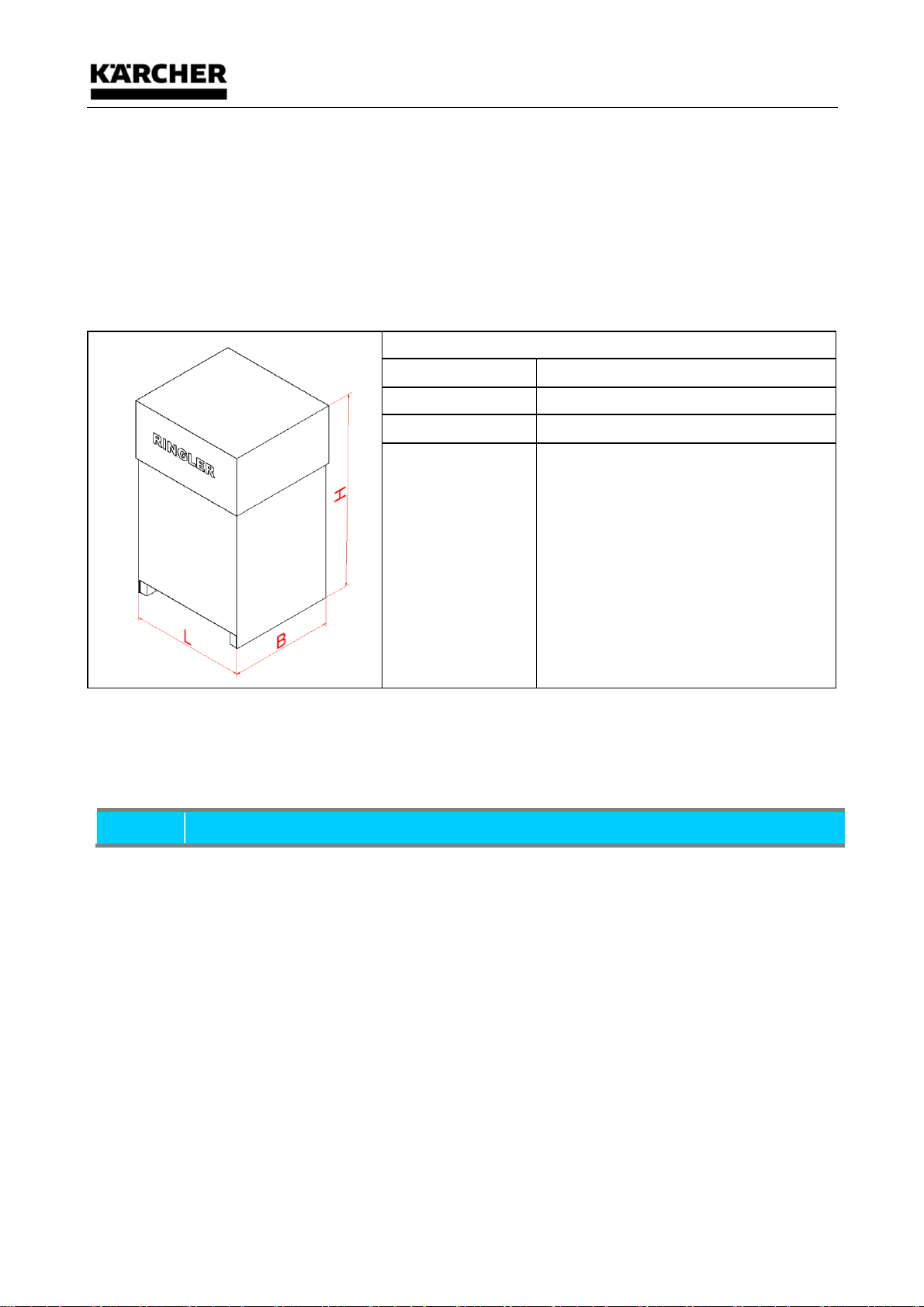
2.2.1 Dimensions and weight
Packing
L (mm)
1200
B (mm)
800
H (mm)
1700
Weight incl.
packing (kg)
173
2.3 Unpacking
Make sure that no components are left in the packaging.
Scope of delivery: -Suction device
-Technical Manual
NOTICE
The suction unit of Ringler Apparatebau is delivered installed on a pallet. If the device is to be lifted from
the pallet with a forklift, however, the dust container must be taken away first to avoid damage to it.

Delivery, internal transportation, unpacking
11/33
2.4 Packaging material
The packaging materials must be disposed of in accordance with the valid legal requirements.
Correct disposal of this product (electrical waste) (applicable in the countries of the European Union
and other European countries with a separate collection system)
The identification on the product and on the associated literature states that it must not be disposed of
along with normal domestic waste at the end of its service life. Please dispose of this device
separately from other waste, in order to prevent damage to the environment or to human health
through uncontrolled waste disposal. Please recycle this device, in order to promote sustainable re-
use of material resources. Private users should contact the dealer from whom they purchased the
product or the competent authorities, in order to find out how they can recycle the device in an
environmentally-
friendly manner. Commercial users should contact their supplier. This product must not be disposed of
along with other commercial waste.
Recycling symbol
This information must be observed in order to preserve the environment!
2.5 Storage conditions
2.5.1 Information for storage
Should the industrial exhauster not be operated for a longer period of time, so it has to be stored in
dry, dust and vibrationless rooms.
Temperature T: -10…+40°C
Humidity: max. 85%

Appliance description
12/33
3 Appliance description
3.1 Intended Use
NOTICE
• This device, which has been delivered ready for operation, is designed as a dry vacuum cleaner for
commercial and industrial applications e.g. in hotels, schools, hospitals, factories, shops, offices
and rent transactions. It is particularly suitable for vacuuming up dust.
Dedusting units are suitable for connection to dust-generating machines.
• Caution! This device is only meant for dry application and must not be used or stored outdoors
under wet conditions!
The machine may only be operated when all filters installed correctly and undamaged.
WARNING
3.1.1 Dust class "M"
Observe warning sign on the device!
Dust class "M" contains dust class "L".
• The device is suitable for dusts hazardous to health and not flammable with workplace limit
≥0.1mg/m³ according to dust class M (max. permeability <0.1%) according to DIN EN
60335-2-69 Annex AA:2010.
3.2 Non-Intended Use
NOTICE
For all personal injuries and material damages, which are caused by a not -asdirected-
use, the operator and not the manufacturer of the machine is
responsible for !
• May not be used outdoors!
WARNING
• This device is not suitable for taking up and extracting combustible dusts.
• This device is not suitable for taking up and extracting flammable liquids (flammable, highly
flammable, highly flammable hazardous substances according to Directive 67/548/EEC)
(Flash Point under 55°C) as well as mixtures of combustible dusts with flammable liquids.
• The vacuum cleaner is not approved for operation in potentially explosive areas!
DANGER
• With improper use may cause explosion and fire!
3.2.1 Dust class "M"
Observe warning sign on the device!
• The device is not suitable for dust class H.
• The device is not suitable for carcinogenic hazardous substances purs. to GefStoffV §10,
TRGS 905 or TRGS 906.
• The device is not suitable for asbestos pursuant to TRGS 519.
NOTICE
A device of build 22 is needed to extract flammable dust!
Layout and function
13/33
4 Layout and function
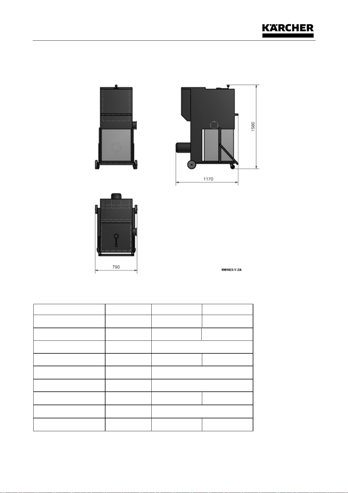
4.1 Main dimensions
4.2 Technical Data
Technical Data
Unit
50 Hz
60 Hz
Voltage
[V]
Δ230 Y400
Δ265 Y460
Frequency
[kW]
2,2
2,55
Protection type
IP 55
Power intake
[A]
Δ7,6 Y4,3
Y4,4
Air displacement volume
[m³/h]
1600
Vacuum
[mbar]
35
Noise level
[dB(A)]
72
74
Weight
[kg]
approx. 150
Efficiency
IE3
86,1% cosφ0,85
86,5% cosφ0,85
Main components
14/33
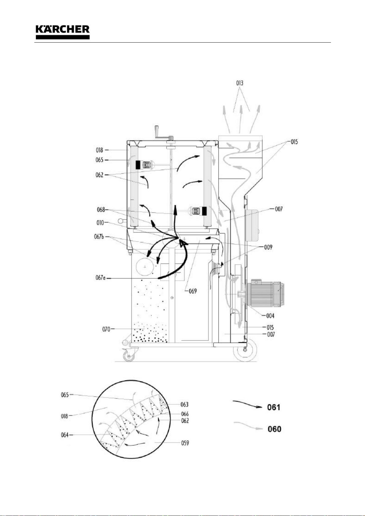
5 Main components
5.1 Chart "Raw air/clean air flow"

Initiation
15/33
6 Initiation
CAUTION
6.1 Initial commissioning
Attention:
• Have electrical work performed by an electrician!
• Set up the device at a regular room temperature, in the dry, on a level area, not outdoors! Latch the
two casters.
• Before commissioning, ensure that the device is assigned enough standing space with the
corresponding safety distance for work and maintenance.
• Testing: The operating voltage of the device is equal to that of the grid. Only then plug in the mains
plug.
• The main switch on the control box serves switching on and off. Red pushbutton pushed (switch
position=0), then the deduster is off. Green pushbutton pushed (switch position=1), then the
deduster is on.
Attention:
• Check motor rotating direction before commissioning! For direction indication, see red arrow
(motor housing). If the rotating direction is incorrect, reverse polarity of the device in the mains plug
with the included phase inverter. Turning the pins integrated in the insulation part of the plug with a
screwdriver changes the rotating direction of the fan drive. The wrong rotating direction causes
overheating, lower air volume flow and a lower extraction output.
WARNING
The machine must only be operated in TN grids with earthed neutral conductor!
6.2 Connection to an extraction source (e.g. processing machine)
• Before connecting the device to the processing machine, a function test must be performed according
to the later monthly inspection.
• The device must be firmly connected to the extraction source with a hose/pipe system (processing
machine).
• When connecting an extraction hose, ensure that only electrically conductive hoses are used and that
the electrical connection between the hose and socket is impeccable. If a "spiral hose" is used, the
metal spiral must be stripped and pushed against the wall of the extraction socket with a pipe clamp
after pushing on the hose (earthing option).
• After connection of the extraction hose (and poss. the accessories) to the processing machine, the
deduster is started up first Push the green pushbutton at the main switch (switch position 1), then
switch on the processing machine.
• When switching off, observe the reverse order. First switch off the processing machine, then push the
red pushbutton at the main switch of the deduster only (switch position 0) (switch off).
• Generally, additional hose length and accessories always mean additional pressure loss. The best
working conditions are present when a dust/chip source is connected to the suction device directly by
the shortest possible hose connection!
• During operation, the site of the machine must not be changed!
Initiation
16/33
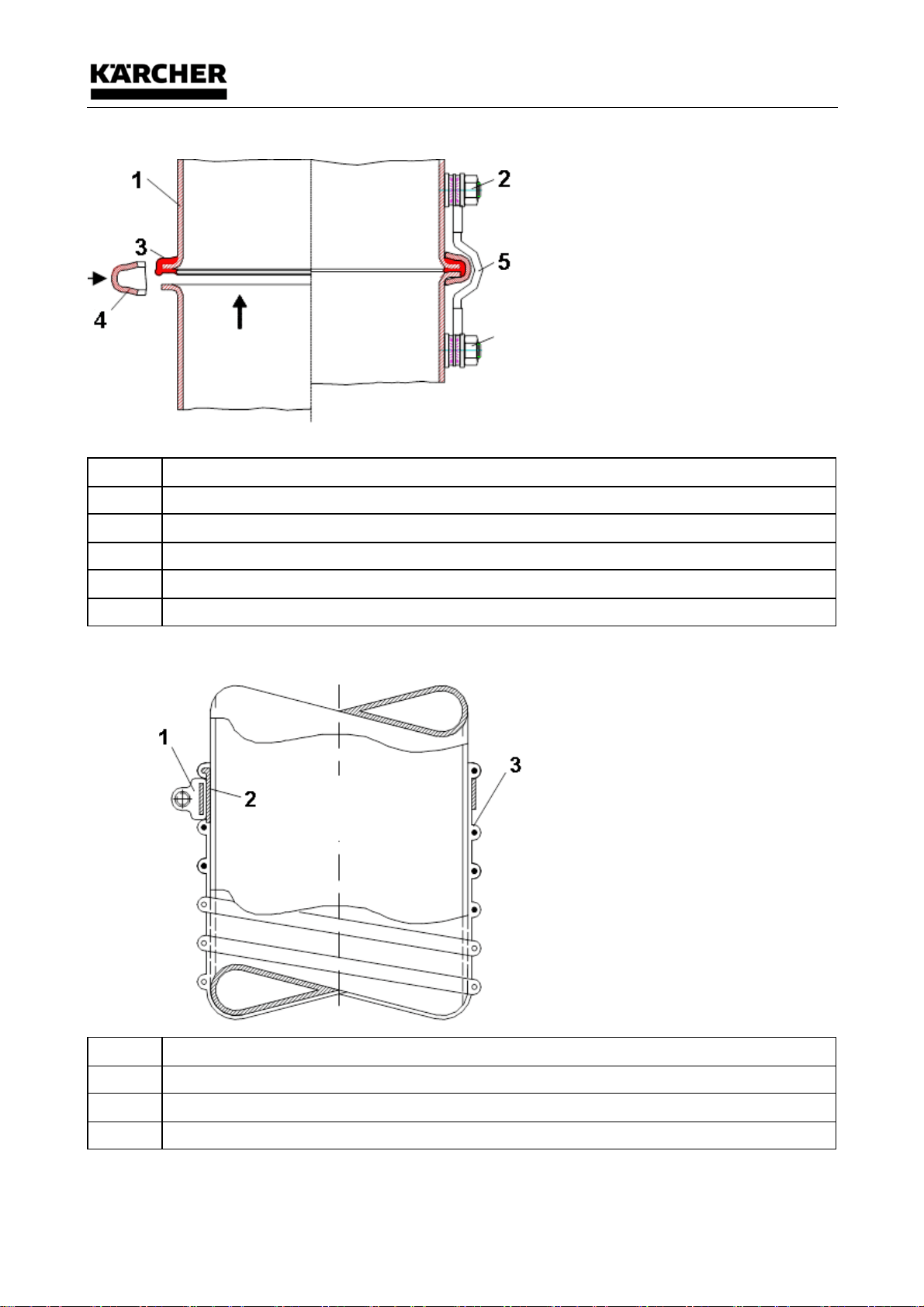
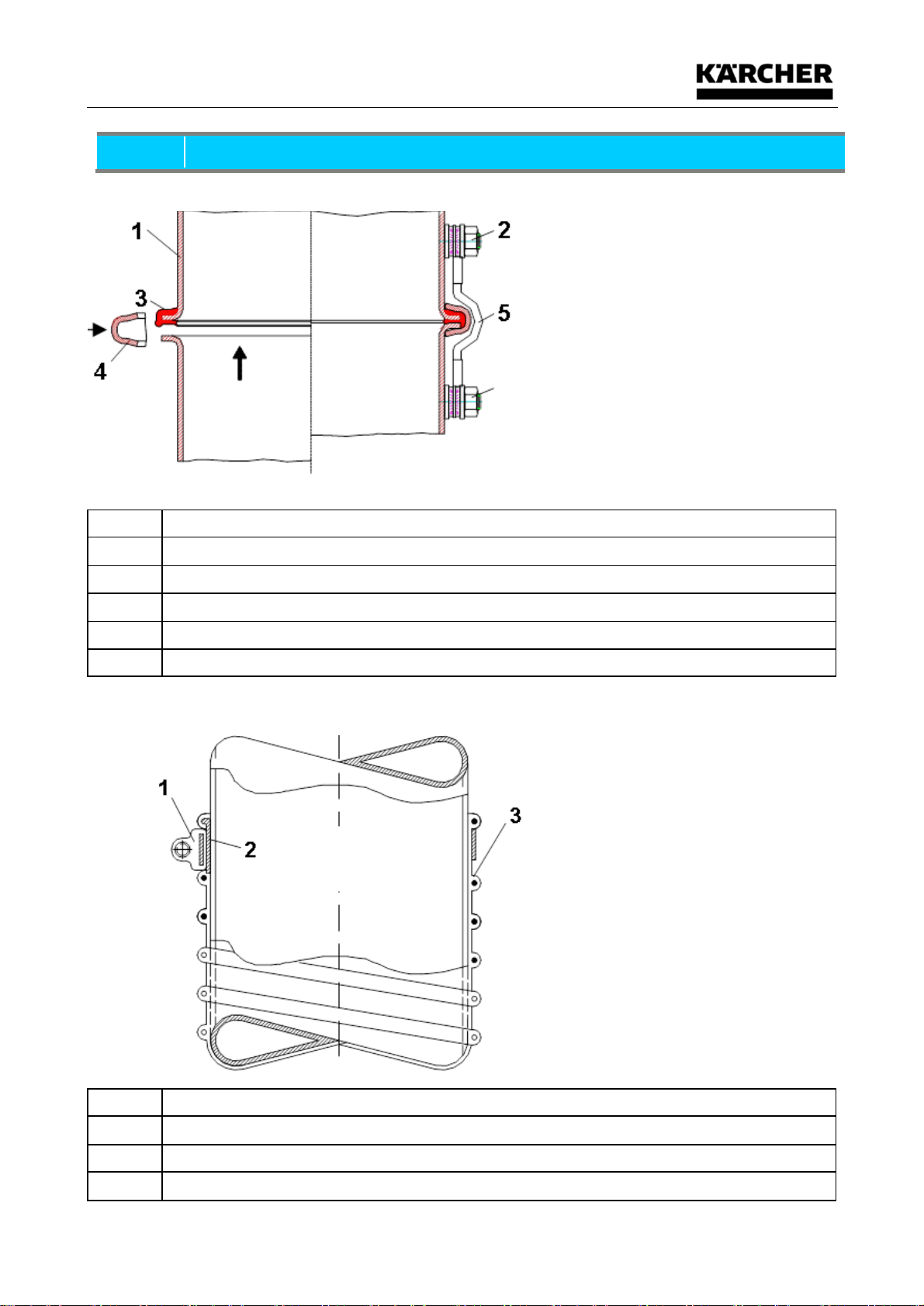
6.3 Assembly Instruction Pipes
Item
Description
1
Pipes
2
Earthing point
3
Knurled sealing ring
4
Clamp ring
5
Earthing strand 6mm²
6.4 Assembly Instructions Hose
Item
Description
1
Hose clamp
2
Wire spiral, bent, contact with blank steel tube
3
Spiral hose, type "D"
Initiation
17/33
NOTICE
6.5 Assembly Instruction Pipes
Item
Description
1
Pipes
2
Earthing point
3
Knurled sealing ring
4
Clamp ring
5
Earthing strand 6mm²
6.6 Assembly Instructions Hose
Item
Description
1
Hose clamp
2
Wire spiral, bent, contact with blank steel tube
3
Spiral hose, type "D"

Initiation
18/33
Operation
19/33
7 Operation
7.1 Minimum air volume flow control
Observe that the extracting air volume flow does not undercut a minimum value. The monitoring facility
must be adjusted with the differential pressure switch to this respective minimum volume flow depending
on the extraction socket cross-section of the processing machine.
The new setting/change of the differential pressure switch must only be performed by an instructed
person.
The device is switched off first. On the transparent plastic cover of the differential pressure switch, you can
select the desired vacuum from the outside with an adjustment tool (hexagon socket wrench, size 6). The
desired value is to be assigned to the white triangular mark. The device is ready for operation again and
adjusted to the new required minimum air volume flow.
The following table shows the values for the setting work to be performed:
Extraction socket cross-
section
q (cm
2
)
Socket Ø
(mm)
Minimum air volume flow
V min. (m
3
/h)
Setting value on the scale
P (Pa)
< 50,3
80
362
3260
< 78,6
100
565
3110
< 113,0
120
813
2740
< 154,0
140
1100
2460
7.2 Cleaning of the filter cartridge
The more tightly the deposits on the cartridge surface become, the less air will flow through the cartridges and the air
volume flow will reduce.
Practically, the minimum air volume flow was defined at 20 m/s. The minimum air volume flow is monitored via the
differential pressure switch.
If the lower limit (minimum air volume flow) is reached, the yellow warning lamp will light up. The device
must be cleaned.
For this, use the crank for manual cleaning on the filter chamber cover. Turn the crank clockwise
approx. 10x -20x slowly in the direction of the arrow.
CAUTION
• Operating the crank in the opposite direction (counter-clockwise) may damage the filter cartridge.
• Cleaning of the crank must only start when the motor has come to a standstill.

Operation
20/33
7.3 Emptying the collection container
The dust/chip bag in the container must be emptied when the maximum fill height is reached - see inspection
through the sight window - and always after daily use of the deduster. Chip and dust deposits to the upper
edge of the container's sight window mean: "Fill level for medium deposit" reached, best work operation no
longer ensured.
It is recommended to replace the dust/chip bag with a new one at once:
• Fasten the two latchable running rollers of the deduster.
• The two running rollers must not point inwards when shunting the container; otherwise, the container
cannot be moved properly.
• The device must be switched off and the mains plug must be removed.
• By pushing up the grip of the lifting and lowering device of the container (remains on top by the
latching device), the container is disconnected from the filter chamber and moved down to the bottom
with the lifting and lowering device.
• The dust/chip bag must be closed carefully.
• Removal of the dust/chip bag from the collection container may take place "on site" or at an internal
disposal point. Disposal must take place professionally and according to the local provisions!
• When inserting a new dust/chip bag, ensure that it is smoothly applied to the walls of the container
and throwing as few folds at the upper edge as possible.
• Push up the part of the dust/chip bag that protrudes over the container until the two container holders
and the rubber sealing sleeve (connection between vacuum line of the container and the filter
chamber/raw air side) are free.
• Push the container to the holding device and carefully push down the grip of the lifting and lowering
device all the way.
• The rubber seal at the upper edge of the container must be pushed against the filter chamber air-tight.
• Then the RE 120 is ready again.
CAUTION
• Generally observe that the air volume flow is not interrupted at a newly inserted dust/chip bag or a
dust/chip bag that has not collected any dust/chips yet, when switching on the deduster. This would
be the case, e.g. if the hose was completely clogged or if all pushers were closed at a branch or a Y-
piece. The consequence would be that the dust/chip bag would be sucked into the filter cartridge
through the large vacuum (Pmax at air volume flow 0 m/s) at once after activation.
• If the empty filter bag is sucked into the filter cartridge (e.g. by the above situation), a new filter bag
must be inserted since it cannot be excluded that the dust/chip bag was damaged.

Troubleshooting and fault elimination
21/33
8 Troubleshooting and fault elimination
8.1 Safety instructions
WARNING
• Before starting any work on the industrial vacuum cleaner, but particularly before opening covers of
live or moving parts, the industrial vacuum cleaner or system must be correctly disconnected from
the mains and the drive unit must have stopped
• The measures specified below may only be withdrawn when the industrial vacuum cleaner is
completely reassembled and the maintenance is concluded.
• The usual safety regulations are, for example, in accordance with VDE 0105:
– Disconnect from mains
– Provide a safeguard to prevent unintentional restarting
– Check that the equipment is not live
– Cover or shield adjacent live parts.

Troubleshooting and fault elimination
22/33
8.2 Initial fault elimination measures
NOTICE
könne
All the errors mentioned in the table below may be eliminated by yourself. In case of major problems
or other failures please contact the customer service of Ringler immediately.
Tel. ++49-(0)7171-94888-0
Perform maintenance tasks in accordance with the description in the Maintenance/Servicing chapter
Interference
Possible cause
Remedy
Motor is not running
Mains connection line
is not plugged in.
Plug in plug.
Motor protection switch tripped
Switch on motor protection switch.
Pre-fuse defective
Replace 16 A slow-acting fuse
Cable break
Replace mains connection line
Extraction output too low
Filter cake too large
clean
Container overfilled
Replace dust/chip bag
Vacuum line
Container / raw air
space clogged
Check permeability, if
applicable,
remove contamination
Chip bag is sucked in
Check rubber seal of filter chamber
/ container and repair if required
Rotary direction incorrect
Reverse plug polarity
Filter cartridge clogged
Check cleaning process, replace cartridge
if required
Dust penetration in the
clean air area
Filter cartridge worn or damaged
Insert new filter cartridge at once!!!
Tight fit of the filter cartridge
no longer ensured
Tighten clamping screws
Seal of cleaning shaft/filter cartridge
defective
Replace seal
Increase of volume
Wrong rotating direction of the fan
Reverse polarity of CEE plug
Component(s) have come loose
Check tight fit of all machine
parts
Maintenance/Repair
23/33
9 Maintenance/Repair
Before starting work remove the plug from the wall socket!
9.1 Maintenance regulations
NOTICE
• Careful and periodical inspections and maintenance works are necessary to enable an early detection
and elimination of possible errors before they cause bigger problems and damages.
• Ringler assumes liability and guarantee only in case of proper use and compliance with the following
maintenance instructions.
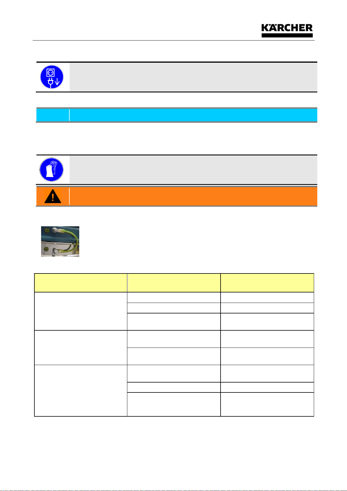
Suitable work gloves must always be worn when carrying out maintenance and service tasks,
in order to prevent injuries and soiling with contaminated substances
WARNING
• These works may only be carried out by an electrician.
• When replacing or repairs the facility all earth conductors are connected again!
9.2 Maintenance intervals table
Interval
(for 1-shift operation)
Check
Maintenance work
Daily
Device or parts of it for damage
visual inspection
Cable connection for damage
visual inspection
Is there a dust/chip bag in the
container?
visual inspection
Monthly
Minimum volume control (yellow
warning lamp)
Function test
Can leaks be found at the filter
(dust vanes)
Safety inspection
Annual
Filter cartridge
Replace filter cartridge on
demand
Bearing of the suction turbine
Replace bearing on demand
Visual inspection whether there
is any dust deposited in the fan
room; remove dust if required.

Maintenance/Repair
24/33
9.3 Replacing the filter cartridge
After an extended operating time, the filter cartridge must be replaced with a new one.The reason for this is
the fact that the pores of the filter material will clog slowly over time and can no longer be cleaned. The filter
cartridge must be replaced when the cleaning intervals are growing disproportionately short. The rated air
volume flow for drive mode is no longer warranted.If the visual inspection in the clean air area of the device
leads to dust penetration (dust vane), this means that the wear threshold of the filter cartridge has been
reached and that replacement is also mandatory.
WARNING
• At the work it is absolutely necessary to wear personal protection equipment (single-way suits,
protecting mask and protective goggles)!
• While carrying out this work, an endangering of other persons must be ruled out!
9.4 Procedure when replacing the filter cartridge
• Switch off the device and disconnect it from the mains!
• Fasten the two latchable casters of the deduster.
• Remove the manual cleaning crank.
• Turn out the 8 screws M6 of the filter chamber cover and remove the cover.
• Remove the earthing cable from the lid of the filter cartridge.
• The filter cartridge is fastened with 3 centring mandrels. Pull out the filter cartridge via the cleaning shaft
by slight canting to overcome the resistance produced inside the filter cartridge with the 2 wipers.
The new filter cartridge is inserted in the reverse order.
Comments:
• Please observe that the felt seal attached to the crank is not damaged.
• First slightly loosen the 8 screws "crosswise", and then screw open all the way. When screwing shut,
also screw on the screws "crosswise", then screw in opposing screws tightly!
• Removal of the old and installation of the new filter cartridge should only be performed by qualified and
instructed staff.
• Visually inspect when replacing the filter chapter. In particular, observe possible dust vanes or other
damage to the cleaning shaft, rubber wipers, etc.
• The support face for the filter cartridge rubber seal must be cleaned thoroughly especially before
installation of the cartridge to prevent possible leaks.
• Dispose of the filter cartridge in a container that can be closed (e.g. plastic bag) under observation of
the already-described safety provisions and according to the local rules. Observe that a particle filter
mask P2 must be worn for the above work.
NOTICE
The vacuum line of the container to the filter chamber/raw air area of the device must be inspected for
clogging at each replacement of the dust/chip bag. Clogging of the vacuum line will lead to the dust/chip
bag being sucked into the inner area of the filter cartridge and thus to strong reduction of the volume flow or
interruption of the extraction function.
Maintenance/Repair
25/33
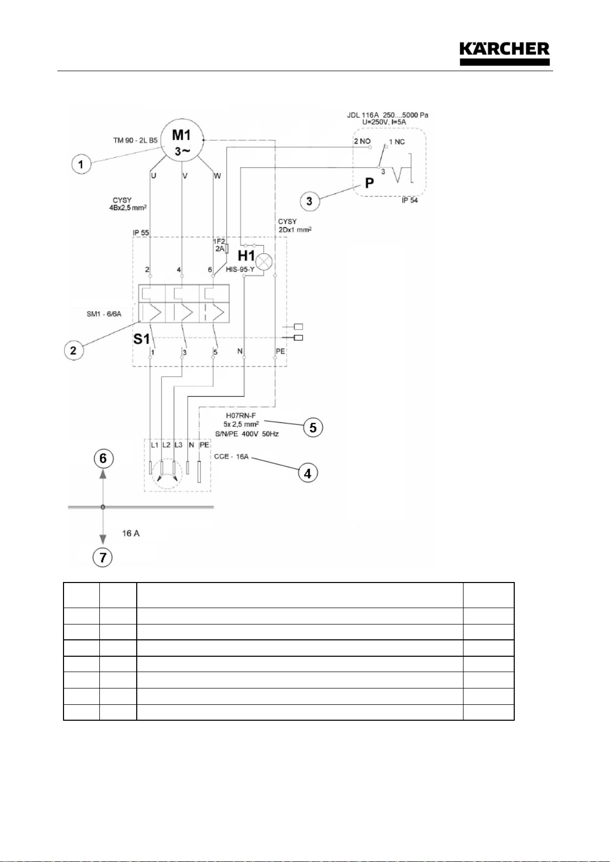
9.5 Circuit diagram
No.
Dwg.
Description
Manufactu
rer
1
M1
Asynchronous. Motor TM90–2L, B5.3~50Hz, 400V, 2.2kW, 2800 rpm, 4.6A, IP 54
EMP
2
S1
Motor protection switch and main switch SM1 – 6, 690V, 3~50Hz, 4-6A, IP 55
OEZ
3
P
Differential pressure switch JDL 116A, 250…5000 Pa, U=250V AC, I=5A, IP54
ALRE
4
H1
Yellow lamp, HIS-95-Y, 230V AC, IP 54
OEZ
5
Rubber cable H07RN-F, 5x 2.5mm², S/N/PE, 400V, 50Hz
6
Dedusting system RE 120
7
Customer, pre-fuse on site: 16 A slow-acting

Decommissioning, storage
26/33
10 Decommissioning, storage
WARNING
• Switch the device off and remove the mains plug from the mains socket.
• Roll up the connection cable.
• Empty the collecting tank, in accordance with the instructions in the chapter "Operation, Control".
• Cleaning of the device as specified in the chapter “Maintenance, Repair".
• When vacuuming up aggressive substances, rinse out the tank with clean water.
• Store the device in a dry place and out of reach of unauthorized personnel.
• "ATTENTION" - This product should be kept indoors only!
Disposal
27/33
11 Disposal
WARNING
• Note preceding chapter "Decommissioning, Storage"!
• The filter inserts must be disposed of separately in accordance with environmental standards,
depending on the medium vacuumed up.
Dispose of the device in accordance with the valid legal regulations.
Correct disposal of this product (electrical waste) (applicable in the countries of the European Union and
other European countries with a separate collection system)
The identification on the product and on the associated literature states that it must not be disposed of
along with normal domestic waste at the end of its service life. Please dispose of this device separately
from other waste, in order to prevent damage to the environment or to human health through
uncontrolled waste disposal. This product must not be disposed of along with other commercial waste.
Spare Parts List
28/33
12 Spare Parts List
12.1 Components
12.1.1 Side view "intake socket closed"
Spare Parts List
29/33
12.1.2 Side view "intake socket cross-section"
Spare Parts List
30/33
12.1.3 Front view "filter housing, transport grip" and view "Motor, filter chamber cover"
Spare Parts List
31/33
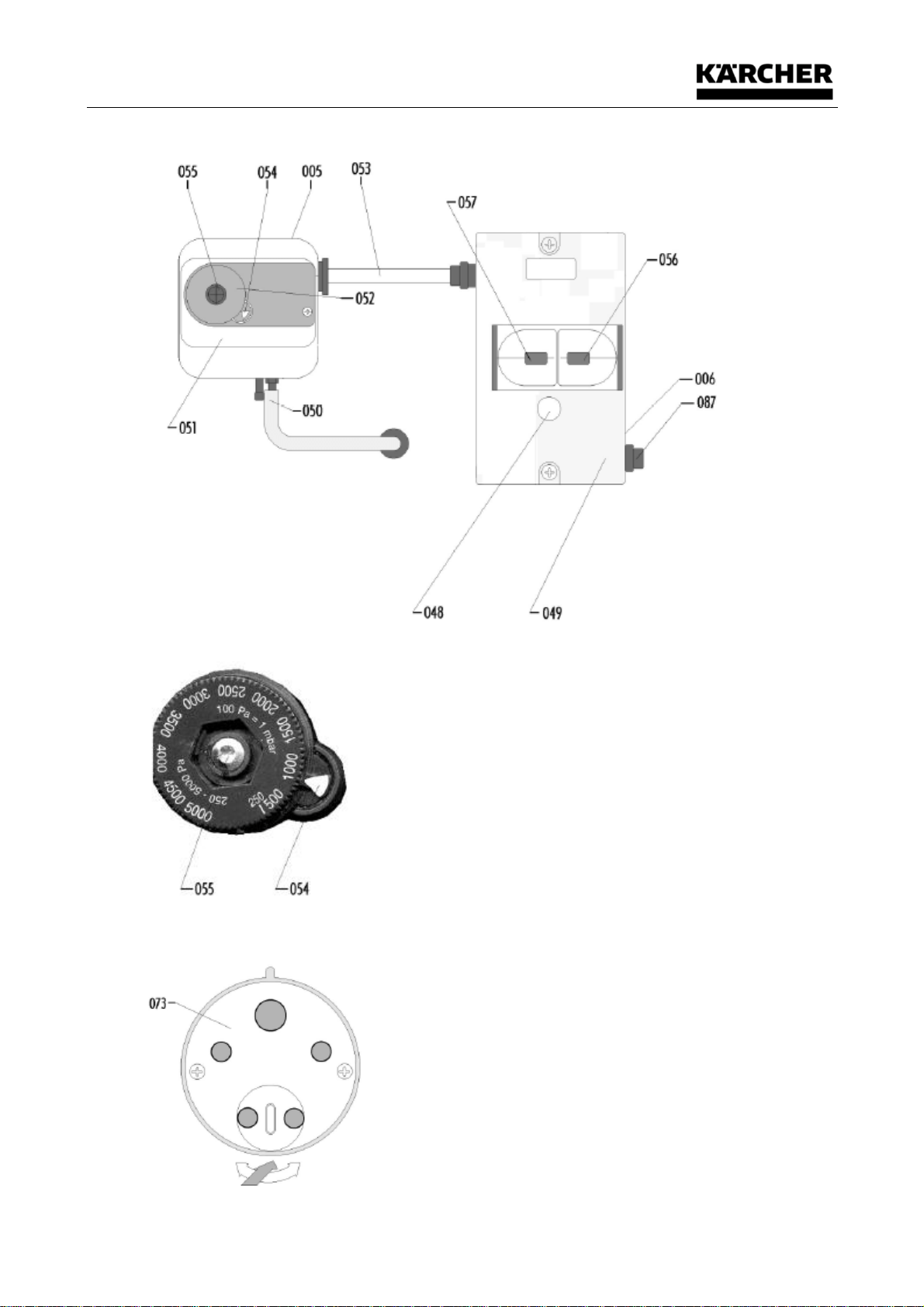
12.1.4 Details of motor protection switch (main switch)
12.1.5 Detail differential pressure switch
12.1.6 Detail plug 16A (5-pin with phase inverter)

Spare Parts List
32/33
Item
Qty.
Unit
Component number
Version
DESIGNATION
001
1
Piece
0350308
Filter cartridge, M, 9m²
002
1
Piece
0400121
Electrical motor FDR 90-L 2.2 kW
005
1
Piece
0040583
Differential pressure switch DDS, JDL 116A ,
006
1
Piece
0040584
Motor protection switch SM1-6 6A,
012
1
Piece
0220101
Roller, D160
021
1
Piece
0220099
Guide roller, latching, D75B
024
1
Piece
1100401
Special container RE120
028
1
Piece
0501003
Rubber seal 20x3mm, 3m long
030
1
Piece
0450192
Rubber wiper for filter cleaning
031
1
Piece
0451031
Rubber sealing, 20x16 mm, 580x580, L=2,4 m
035
1
Piece
0450168
Rubber sealing sleeve
037
1
Piece
1040585
Mains connection line 5x2.5², 5m, with plug 16A
(5-pin with phase inverter)
038
1
Piece
0090123
Simmerring 12x27x7 with aluminium holder
043
1
Piece
2220022
Container running roller, ø75
048
1
Piece
0040586
Signal lamp yellow
073
1
Piece
0040587
Plug 16A (5-pin with phase inverter)
087
1
Piece
0040588
Fuse 1F2 (2A) with insert
093
1
Piece
2600524
Hose clamp for pos.69
10
Piece
0630253
PE disposable bag 1200x1000x0.1
1
Piece
0050001
Hose clamp 50-70mm
1
0451031
Rubber seal housing opening to container
2
0450023
Yard goods
Seal, seat of filter cartridge at the bottom
(is glued on with Pattex)
140
1
0501000
Hand cleaning crank for RE 115 / RE 120

EEC-Declaration of Conformity
33/33
13 EEC-Declaration of Conformity
EC Declaration of Conformity in accordance with the
Machinery Directive 2006/42/EC Appendix II 1A
The product described below:
This declaration shall cease to be valid if the machine is modified without our prior approval.
Designation: Deduster
Type: ID 130/22
Serial number: 99825060xxxxxx
Year of build: 02.2022
produced by:
Kärcher Industrial Vacuuming GmbH
Robert Bosch Straße 4-8
D 73550 Waldstetten
Person authorized for the
compilation of technical documents
Tel: ++49(0)7171-94888-0
Fax: ++49(0)7171-94888-28
e-mail: info@ringler.kaercher.com
Alexander Haag
Dept.: Design/Construction
Robert Bosch Straße 4-8
D 73550 Waldstetten
complies with the following EC directives:
EC Directive (2006/42/EC)
Low-Voltage Directive (2014/35/EU)
EMC Directive (2014/30/EU)
The following harmonized standards were applied:
DIN EN ISO 13857 Safety of machinery; Safety distances to prevent upper and lower
limbs coming into contact with danger points
DIN EN 349 Safety of machinery; Minimum distances to avoid crushing of body
parts.
DIN EN 60335-2-69 Special requirements for vacuum cleaners and water suction
devices for industrial and commercial purposes.
Waldstetten, 10.02.2022 M. Pfister
(Managing Director)