HFC
utilized
R410A
TM
PARTS CATALOG (OBB702)
INDOOR UNIT
SERVICE MANUAL
OUTDOOR UNIT
Models
MXZ-3C24NA MXZ-3C24NA2
-
U1
MXZ-3C30NA MXZ-3C30NA2
-
U1
MXZ-4C36NA MXZ-4C36NA2
-
U1
MXZ-5C42NA MXZ-5C42NA2
-
U1
MXZ-2C20NAHZ MXZ-2C20NAHZ2
-
U1
MXZ-3C24NAHZ MXZ-3C24NAHZ2
-
U1
MXZ-3C30NAHZ MXZ-3C30NAHZ2
-
U1
No. OBH702
REVISED EDITION-C
Please void OBH702 REVISED EDITION-B.
Revision C:
• 3. SPECIFICATION has been corrected.
• Some descriptions have been modified.
Indoor unit service manual
MSZ-FE·NA Series (OBH542)
MSZ-GE·NA Series (OBH548)
MFZ-KA·NA Series (OBH568)
SEZ-KD·NA Series
PLA-A·BA Series (OCH420)
PCA-A·KA Series (OCH455)
PEAD-A·AA Series
SLZ-KA·NA Series (OCH487)
MSZ-FH·NA Series (OBH683)
MVZ-A·AA Series
MSZ-GL·NA Series (OBH732)
MSZ-EF·NA Series (OBH736)
MFZ-KJ·NA Series (OBH752)
MXZ-3C24NA MXZ-3C24NA2
MXZ-3C30NA MXZ-3C30NA2
MXZ-4C36NA MXZ-4C36NA2
CONTENTS
1. TECHNICAL CHANGES ··································· 4
2. PART NAMES AND FUNCTIONS ····················· 5
3. SPECIFICATION ················································ 6
4. NOISE CRITERIA CURVES ···························· 13
5. OUTLINES AND DIMENSIONS ······················ 15
6. WIRING DIAGRAM ·········································· 20
7. REFRIGERANT SYSTEM DIAGRAM ············· 30
8. DATA ································································ 41
9. ACTUATOR CONTROL ··································· 63
10. SERVICE FUNCTIONS ···································· 64
11. TROUBLESHOOTING ····································· 66
12. DISASSEMBLY INSTRUCTIONS ···················· 87
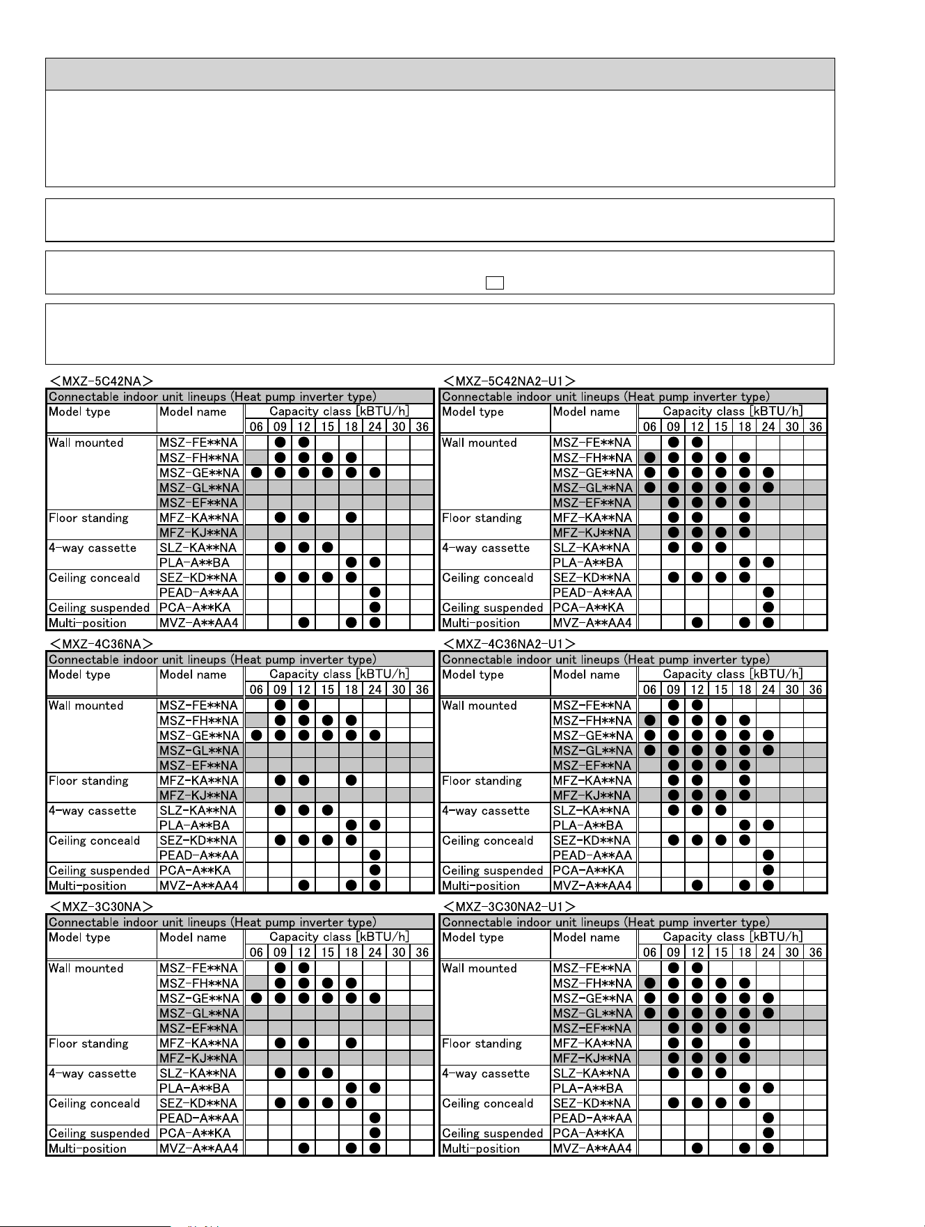
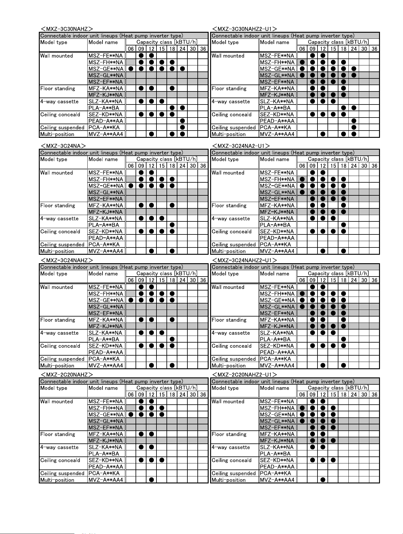
INDOOR UNITS COMBINATION TABLES
2
Use the specifi ed refrigerant only
Never use any refrigerant other than that specified.
Doing so may cause a burst, an explosion, or fire when the unit is being used, serviced, or disposed of.
Correct refrigerant is specified in the manuals and on the spec labels provided with our products.
We will not be held responsible for mechanical failure, system malfunction, unit breakdown or accidents caused by
failure to follow the instructions.
Revision A:
• MXZ-3C24NA, MXZ-3C30NA and MXZ-4C36NA have been added.
Revision B:
• MXZ-3C24/3C30/4C36/5C42NA2 and MXZ-2C20/3C24/3C30NAHZ2-
U1
have been added.
Revision C:
• 3. SPECIFICATION has been changed.
• Some descriptions have been modified.
OBH702C
3
OBH702C
4
TECHNICAL CHANGES
1
MXZ-5C42NA
MXZ-2C20NAHZ
MXZ-3C24NAHZ
MXZ-3C30NAHZ
1. New model
MXZ-3C24NA
MXZ-3C30NA
MXZ-4C36NA
1. New model
MXZ-3C24NA MXZ-3C24NA2 -
U1
MXZ-3C30NA MXZ-3C30NA2 -
U1
MXZ-4C36NA MXZ-4C36NA2 -
U1
MXZ-5C42NA MXZ-5C42NA2 -
U1
MXZ-2C20NAHZ MXZ-2C20NAHZ2 -
U1
MXZ-3C24NAHZ MXZ-3C24NAHZ2 -
U1
MXZ-3C30NAHZ MXZ-3C30NAHZ2 -
U1
1. Outdoor control P.C. board has been changed.
OBH702C
5
PART NAMES AND FUNCTIONS
2
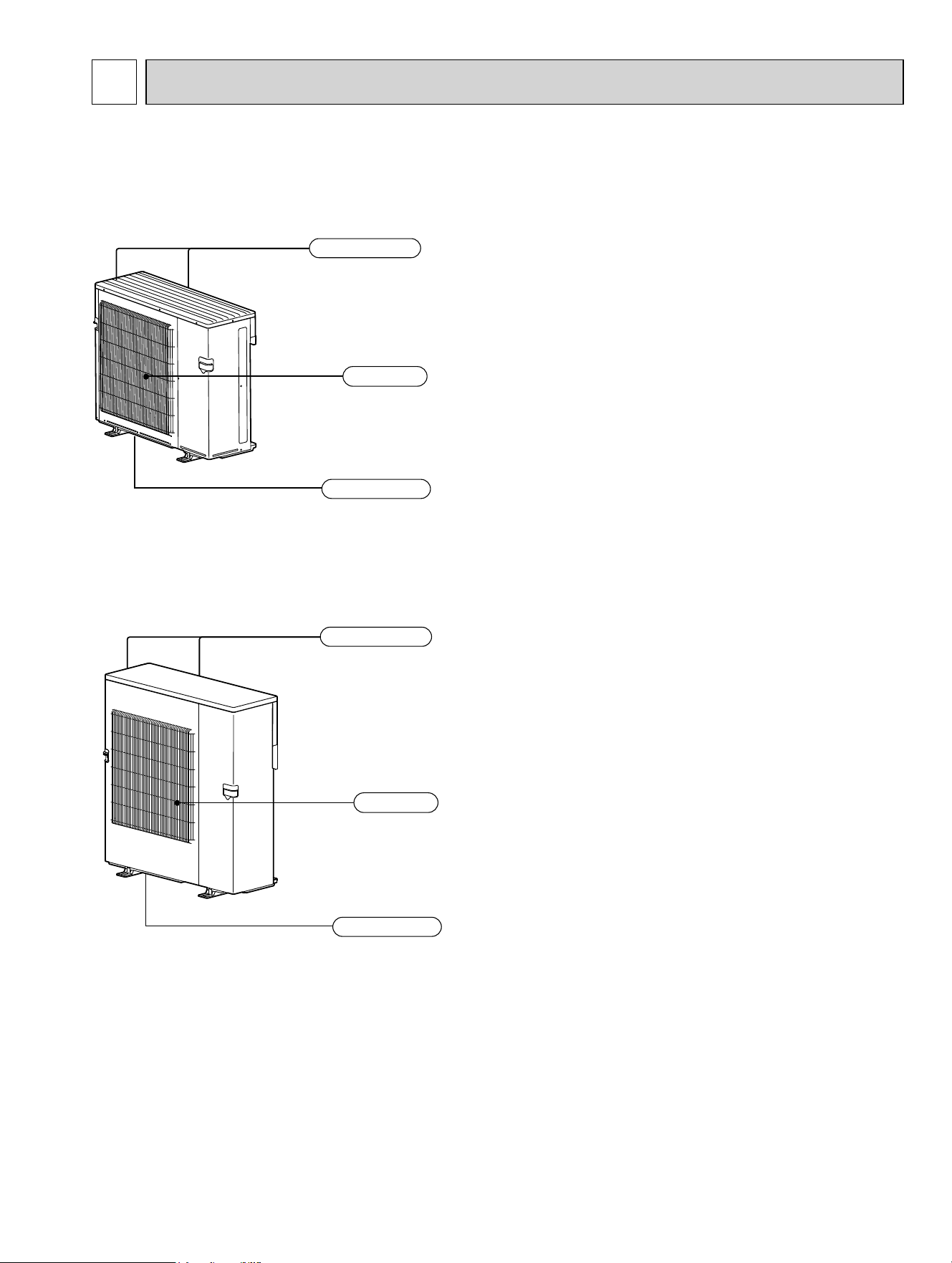
MXZ-5C42NA MXZ-5C42NA2
MXZ-2C20NAHZ MXZ-2C20NAHZ2
MXZ-3C24NAHZ MXZ-3C24NAHZ2
MXZ-3C30NAHZ MXZ-3C30NAHZ2
MXZ-3C24NA MXZ-3C24NA2
MXZ-3C30NA MXZ-3C30NA2
MXZ-4C36NA MXZ-4C36NA2
Air outlet
Drain outlet
Air inlet
(Back and side)
Air outlet
Drain outlet
Air inlet
(Back and side)
OBH702C
6
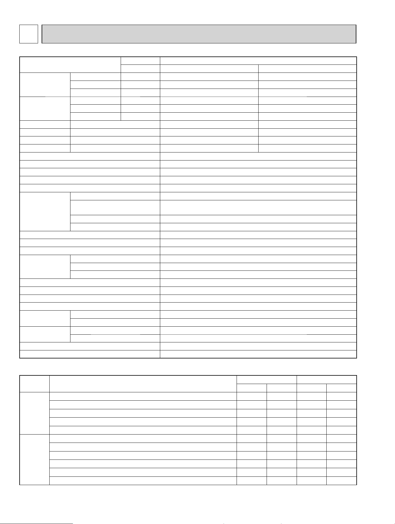
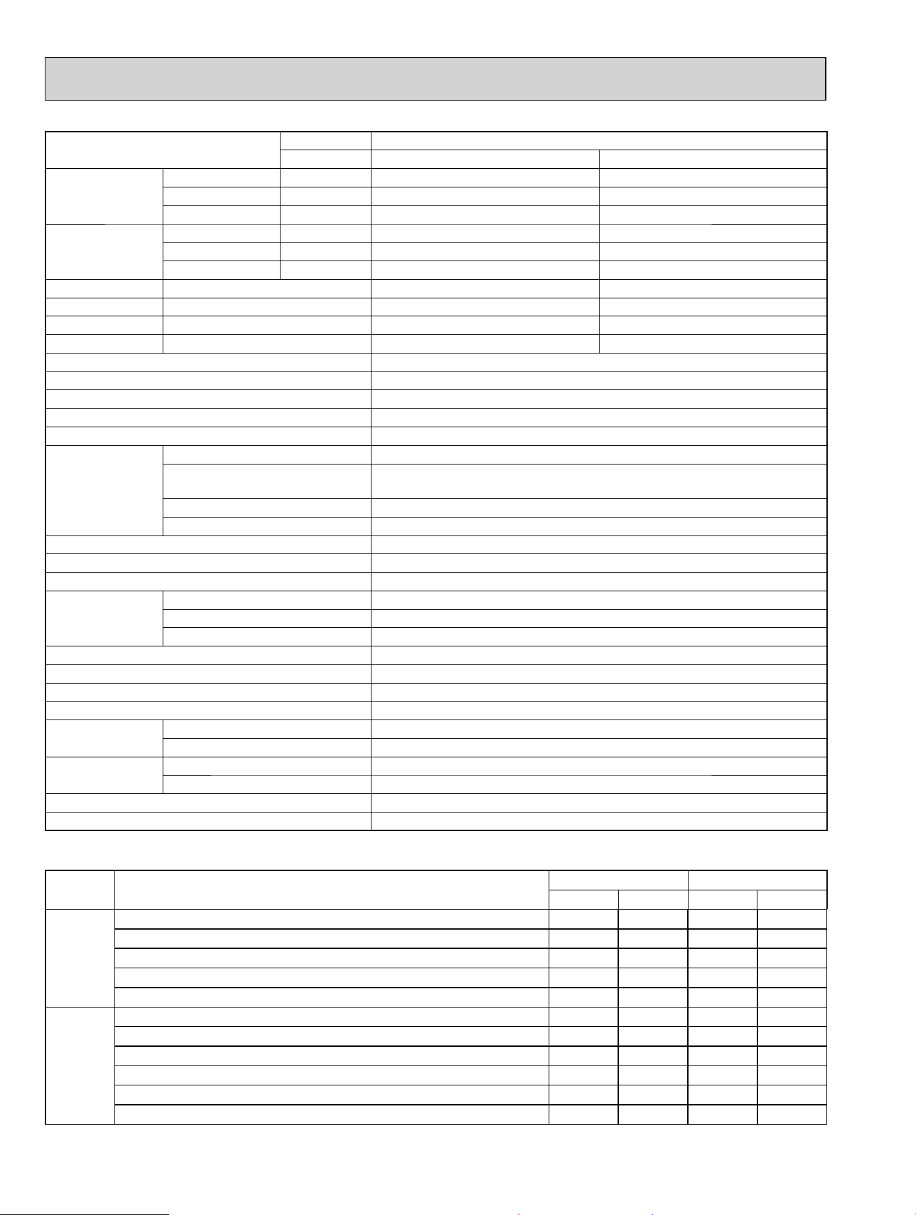
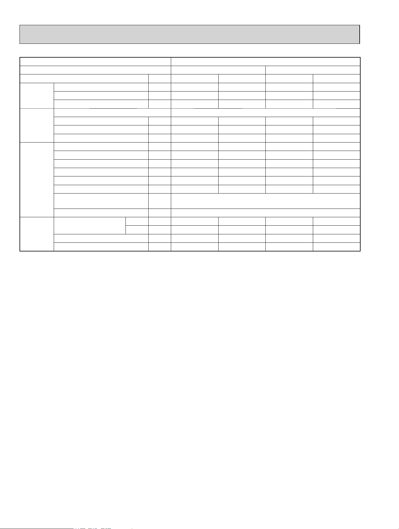
NOTE: Test conditions are based on ARI 210/240.
SPECIFICATION
3
Item
Outdoor model
MXZ-3C24NA MXZ-3C24NA2
Indoor type
Non-Duct (06+09+09) Duct (09+09+09)
Capacity
Cooling *1 Btu/h
22,000 23,600
Heating 47 *1 Btu/h
25,000 24,600
Heating 17 *2 Btu/h
19,600 19,600
Power
consumption
Cooling *1 W
1,620 2,100
Heating 47 *1 W
1,750 1,900
Heating 17 *2 W
2,580 2,440
EER Cooling
13.6 11.2
SEER Cooling
20.0 16.0
HSPF IV(V) Heating
9.8 (7.6) 9.2 (7.6)
COP Heating
4.20 3.80
External fi nish
Munsell 3.0Y 7.8/1.1
Power supply V, phase, Hz
208/230, 1, 60
Max. fuse size (time delay) A
25
Min. circuit ampacity A
22.1
Fan motor F.L.A
2.43
Compressor
Model
SNB220FQGMC
Winding resistance
(at 68 ºF)
Ω
U-V 0.95 V-W 0.95 W-U 0.95
R.L.A
12
L.R.A
13.7
Refrigerant control
LEV
Sound level dB(A)
51/55
Defrost method
Reverse cycle
Dimensions
W in.
37-13/32
D in.
13
H in.
31-11/32
Weight lb.
NA: 135/NA2: 137
Remote controller
Wireless type
Control voltage (by built-in transformer)
12-24 VDC
Refrigerant piping
Not supplied (optional parts)
Valve size
Liquid in.
1/4
Gas in.
A:1/2 B,C:3/8
Connection method
Indoor
Flared
Outdoor
Flared
Refrigerant charge (R410A) lb.
6lb. 13oz.
Refrigeration oil (Model) fl oz. (L)
23.7 (0.7) (FV50S)
Unit: °F
Mode Test
Indoor air condition Outdoor air condition
Dry bulb Wet bulb Dry bulb Wet bulb
Cooling
*1: "A" Cooling steady state at rated compressor speed 80 67 95 (75)
"B-2" Cooling steady state at rated compressor speed 80 67 82 (65)
"B-1" Cooling steady state at minimum compressor speed 80 67 82 (65)
Low ambient cooling steady state at minimum compressor speed 80 67 67 (53.5)
Intermediate cooling steady state at intermediate compressor speed 80 67 87 (69)
Heating
*1: Standard rating-heating at rated compressor speed 70 60 47 43
*2: Low temperature heating at maximum compressor speed 70 60 17 15
Maximum temperature heating at minimum compressor speed 70 60 62 56.5
High temperature heating at minimum compressor speed 70 60 47 43
Frost accumulation at rated compressor speed 70 60 35 33
Frost accumulation at intermediate compressor speed 70 60 35 33
OBH702C

7
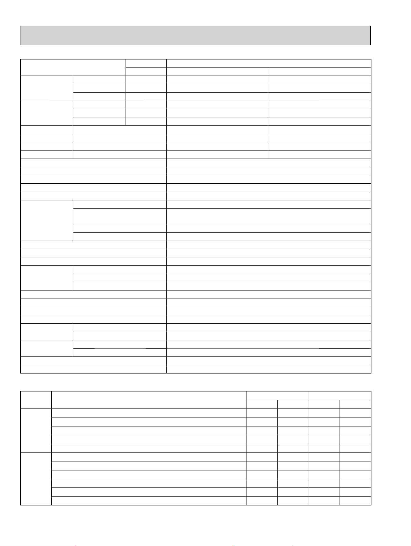
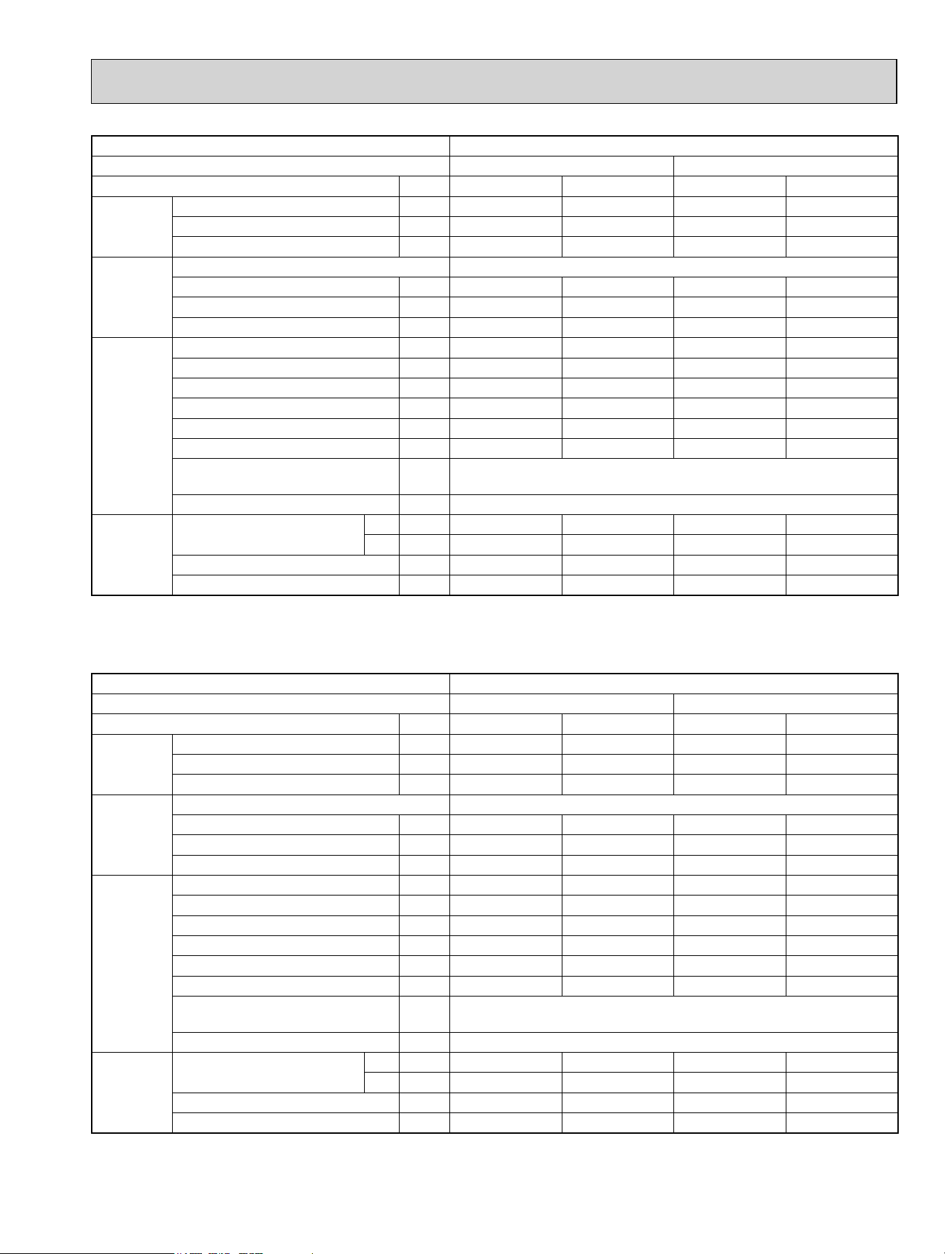
NOTE: Test conditions are based on ARI 210/240.
Item
Outdoor model
MXZ-3C30NA MXZ-3C30NA2
Indoor type
Non-Duct (09+09+12) Duct (09+09+12)
Capacity
Cooling *1 Btu/h
28,400 27,400
Heating 47 *1 Btu/h
28,600 27,600
Heating 17 *2 Btu/h
21,000 21,000
Power
consumption
Cooling *1 W
2,680 2,840
Heating 47 *1 W
2,150 2,220
Heating 17 *2 W
2,740 2,820
EER Cooling
10.6 9.6
SEER Cooling
19.0 16.2
HSPF IV(V) Heating
10.6 (8.0) 9.6 (8.0)
COP Heating
3.90 3.64
External fi nish
Munsell 3.0Y 7.8/1.1
Power supply V, phase, Hz
208/230, 1, 60
Max. fuse size (time delay) A
25
Min. circuit ampacity A
22.1
Fan motor F.L.A
2.43
Compressor
Model
SNB220FQGMC
Winding resistance
(at 68 ºF)
Ω
U-V 0.95 V-W 0.95 W-U 0.95
R.L.A
12
L.R.A
13.7
Refrigerant control
LEV
Sound level dB(A)
52/56
Defrost method
Reverse cycle
Dimensions
W in.
37-13/32
D in.
13
H in.
31-11/32
Weight lb.
NA: 135/NA2: 137
Remote controller
Wireless type
Control voltage (by built-in transformer)
12-24 VDC
Refrigerant piping
Not supplied (optional parts)
Valve size
Liquid in.
1/4
Gas in.
A:1/2 B,C:3/8
Connection method
Indoor
Flared
Outdoor
Flared
Refrigerant charge (R410A) lb.
6lb. 13oz.
Refrigeration oil (Model) fl oz. (L)
23.7 (0.7) (FV50S)
Unit: °F
Mode Test
Indoor air condition Outdoor air condition
Dry bulb Wet bulb Dry bulb Wet bulb
Cooling
*1: "A" Cooling steady state at rated compressor speed 80 67 95 (75)
"B-2" Cooling steady state at rated compressor speed 80 67 82 (65)
"B-1" Cooling steady state at minimum compressor speed 80 67 82 (65)
Low ambient cooling steady state at minimum compressor speed 80 67 67 (53.5)
Intermediate cooling steady state at intermediate compressor speed 80 67 87 (69)
Heating
*1: Standard rating-heating at rated compressor speed 70 60 47 43
*2: Low temperature heating at maximum compressor speed 70 60 17 15
Maximum temperature heating at minimum compressor speed 70 60 62 56.5
High temperature heating at minimum compressor speed 70 60 47 43
Frost accumulation at rated compressor speed 70 60 35 33
Frost accumulation at intermediate compressor speed 70 60 35 33
OBH702C
8
NOTE: Test conditions are based on ARI 210/240.
Item
Outdoor model
MXZ-4C36NA MXZ-4C36NA2
Indoor type
Non-Duct (09+09+09+09) Duct (09+09+09+09)
Capacity
Cooling *1 Btu/h
35,400 34,400
Heating 47 *1 Btu/h
36,000 34,400
Heating 17 *2 Btu/h
26,600 26,600
Power
consumption
Cooling *1 W
3,760 3,940
Heating 47 *1 W
3,020 3,100
Heating 17 *2 W
3,440 3,540
EER Cooling
9.4 8.7
SEER Cooling
19.2 16.0
HSPF IV(V) Heating
11.0 (8.4) 9.8 (8.4)
COP Heating
3.50 3.25
External fi nish
Munsell 3.0Y 7.8/1.1
Power supply V, phase, Hz
208/230, 1, 60
Max. fuse size (time delay) A
25
Min. circuit ampacity A
22.1
Fan motor F.L.A
2.43
Compressor
Model
SNB220FQGMC
Winding resistance
(at 68 ºF)
Ω
U-V 0.95 V-W 0.95 W-U 0.95
R.L.A
12
L.R.A
13.7
Refrigerant control
LEV
Sound level dB(A)
54/56
Defrost method
Reverse cycle
Dimensions
W in.
37-13/32
D in.
13
H in.
31-11/32
Weight lb.
NA: 137/NA2: 139
Remote controller
Wireless type
Control voltage (by built-in transformer)
12-24 VDC
Refrigerant piping
Not supplied (optional parts)
Valve size
Liquid in.
1/4
Gas in.
A:1/2 B,C,D:3/8
Connection method
Indoor
Flared
Outdoor
Flared
Refrigerant charge (R410A) lb.
6lb. 13oz.
Refrigeration oil (Model) fl oz. (L)
23.7 (0.7) (FV50S)
Unit: °F
Mode Test
Indoor air condition Outdoor air condition
Dry bulb Wet bulb Dry bulb Wet bulb
Cooling
*1: "A" Cooling steady state at rated compressor speed 80 67 95 (75)
"B-2" Cooling steady state at rated compressor speed 80 67 82 (65)
"B-1" Cooling steady state at minimum compressor speed 80 67 82 (65)
Low ambient cooling steady state at minimum compressor speed 80 67 67 (53.5)
Intermediate cooling steady state at intermediate compressor speed 80 67 87 (69)
Heating
*1: Standard rating-heating at rated compressor speed 70 60 47 43
*2: Low temperature heating at maximum compressor speed 70 60 17 15
Maximum temperature heating at minimum compressor speed 70 60 62 56.5
High temperature heating at minimum compressor speed 70 60 47 43
Frost accumulation at rated compressor speed 70 60 35 33
Frost accumulation at intermediate compressor speed 70 60 35 33
OBH702C

9
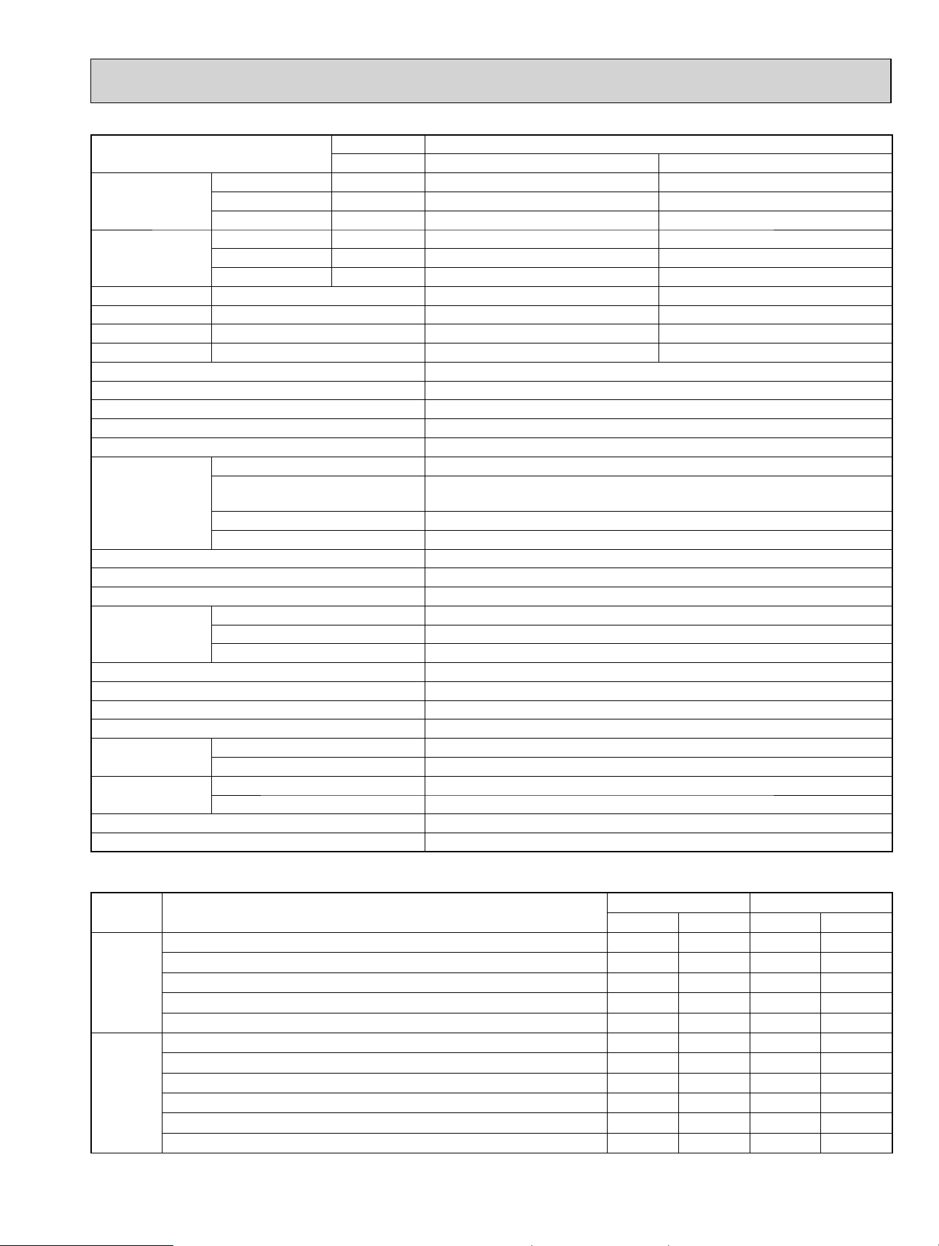
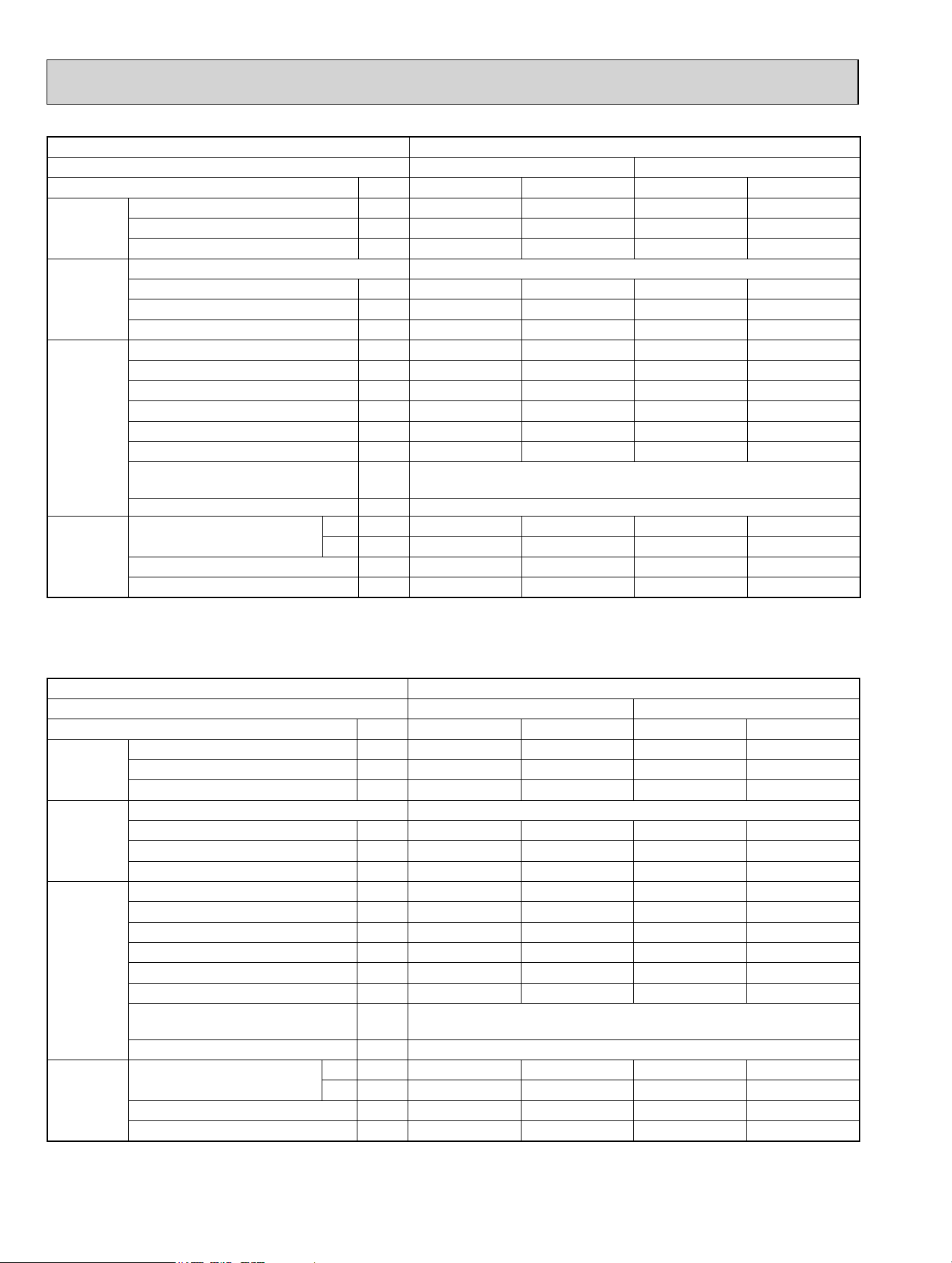
NOTE: Test conditions are based on ARI 210/240.
Item
Outdoor model
MXZ-5C42NA MXZ-5C42NA2
Indoor type
Non-Duct (06+09+09+09+09) Duct (09+09+09+09+09)
Capacity
Cooling *1 Btu/h
40,500 37,500
Heating 47 *1 Btu/h
45,000 41,000
Heating 17 *2 Btu/h
30,500 29,100
Power
consumption
Cooling *1 W
4,403 4,112
Heating 47 *1 W
3,575 3,463
Heating 17 *2 W
4,800 5,500
EER Cooling
9.2 9.0
SEER Cooling
19.7 15.2
HSPF IV(V) Heating
10.3 (7.7) 9.1 (7.7)
COP Heating
3.69 3.47
External fi nish
Munsell 3.0Y 7.8/1.1
Power supply V, phase, Hz
208/230, 1, 60
Max. fuse size (time delay) A
40
Min. circuit ampacity A
NA: 31.9/NA2: 32.5
Fan motor F.L.A
NA: 1.9 /NA2: 2.43
Compressor
Model
MNB33FBTMC-L
Winding resistance
(at 68 ºF)
Ω
U-V 0.30 V-W 0.30 W-U 0.30
R.L.A
20
L.R.A
28.8
Refrigerant control
LEV
Sound level dB(A)
56/58
Defrost method
Reverse cycle
Dimensions
W in.
37-13/32
D in.
13
H in.
41-17/64
Weight lb.
189
Remote controller
Wireless type
Control voltage (by built-in transformer)
12-24 VDC
Refrigerant piping
Not supplied (optional parts)
Valve size
Liquid in.
1/4
Gas in.
A:1/2 B,C,D,E: 3/8
Connection method
Indoor
Flared
Outdoor
Flared
Refrigerant charge (R410A) lb.
8 lb. 13 oz.
Refrigeration oil (Model) fl oz. (L)
37.2 (1.1) (FV50S)
Unit: °F
Mode Test
Indoor air condition Outdoor air condition
Dry bulb Wet bulb Dry bulb Wet bulb
Cooling
*1: "A" Cooling steady state at rated compressor speed 80 67 95 (75)
"B-2" Cooling steady state at rated compressor speed 80 67 82 (65)
"B-1" Cooling steady state at minimum compressor speed 80 67 82 (65)
Low ambient cooling steady state at minimum compressor speed 80 67 67 (53.5)
Intermediate cooling steady state at intermediate compressor speed 80 67 87 (69)
Heating
*1: Standard rating-heating at rated compressor speed 70 60 47 43
*2: Low temperature heating at maximum compressor speed 70 60 17 15
Maximum temperature heating at minimum compressor speed 70 60 62 56.5
High temperature heating at minimum compressor speed 70 60 47 43
Frost accumulation at rated compressor speed 70 60 35 33
Frost accumulation at intermediate compressor speed 70 60 35 33
OBH702C
10
NOTE: Test conditions are based on ARI 210/240.
Item
Outdoor model
MXZ-2C20NAHZ MXZ-2C20NAHZ2
Indoor type
Non-Duct (09+09) Duct (09+12)
Capacity
Cooling *1 Btu/h
18,000 20,000
Heating 47 *1 Btu/h
22,000 22,000
Heating 17 *2 Btu/h
22,000 22,000
Power
consumption
Cooling *1 W
1,334 1,819
Heating 47 *1 W
1,612 1,748
Heating 17 *2 W
3,071 3,224
EER Cooling
13.5 11.0
SEER Cooling
17.0 15.0
HSPF IV(V) Heating
9.8 (7.8) 9.5 (7.8)
COP Heating
4.00 3.69
External fi nish
Munsell 3.0Y 7.8/1.1
Power supply V, phase, Hz
208/230, 1, 60
Max. fuse size (time delay) A
40
Min. circuit ampacity A
NA: 28.9/NA2: 29.5
Fan motor F.L.A
NA: 1.9/NA2: 2.43
Compressor
Model
MNB33FBTMC-L
Winding resistance
(at 68 ºF)
Ω
U-V 0.30 V-W 0.30 W-U 0.30
R.L.A
20
L.R.A
28.8
Refrigerant control
LEV
Sound level dB(A)
54/58
Defrost method
Reverse cycle
Dimensions
W in.
37-13/32
D in.
13
H in.
41-17/64
Weight lb.
187
Remote controller
Wireless type
Control voltage (by built-in transformer)
12-24 VDC
Refrigerant piping
Not supplied (optional parts)
Valve size
Liquid in.
1/4
Gas in.
A,B: 3/8
Connection method
Indoor
Flared
Outdoor
Flared
Refrigerant charge (R410A) lb.
8 lb. 13 oz.
Refrigeration oil (Model) fl oz. (L)
37.2 (1.1) (FV50S)
Unit: °F
Mode Test
Indoor air condition Outdoor air condition
Dry bulb Wet bulb Dry bulb Wet bulb
Cooling
*1: "A" Cooling steady state at rated compressor speed 80 67 95 (75)
"B-2" Cooling steady state at rated compressor speed 80 67 82 (65)
"B-1" Cooling steady state at minimum compressor speed 80 67 82 (65)
Low ambient cooling steady state at minimum compressor speed 80 67 67 (53.5)
Intermediate cooling steady state at intermediate compressor speed 80 67 87 (69)
Heating
*1: Standard rating-heating at rated compressor speed 70 60 47 43
*2: Low temperature heating at maximum compressor speed 70 60 17 15
Maximum temperature heating at minimum compressor speed 70 60 62 56.5
High temperature heating at minimum compressor speed 70 60 47 43
Frost accumulation at rated compressor speed 70 60 35 33
Frost accumulation at intermediate compressor speed 70 60 35 33
OBH702C
11
NOTE: Test conditions are based on ARI 210/240.
Item
Outdoor model
MXZ-3C24NAHZ MXZ-3C24NAHZ2
Indoor type
Non-Duct (06+06+09) Duct (09+09+09)
Capacity
Cooling *1 Btu/h
22,000 23,600
Heating 47 *1 Btu/h
25,000 24,600
Heating 17 *2 Btu/h
25,000 24,600
Power
consumption
Cooling *1 W
1,630 2,360
Heating 47 *1 W
1,725 1,871
Heating 17 *2 W
3,557 3,795
EER Cooling
13.5 10.0
SEER Cooling
19.0 15.5
HSPF IV(V) Heating
10.0 (7.4) 9.0 (7.4)
COP Heating
4.25 3.80
External fi nish
Munsell 3.0Y 7.8/1.1
Power supply V, phase, Hz
208/230, 1, 60
Max. fuse size (time delay) A
40
Min. circuit ampacity A
NA: 29.9/NA2: 30.5
Fan motor F.L.A
NA: 1.9/NA2: 2.43
Compressor
Model
MNB33FBTMC-L
Winding resistance
(at 68 ºF)
Ω
U-V 0.30 V-W 0.30 W-U 0.30
R.L.A
20
L.R.A
28.8
Refrigerant control
LEV
Sound level dB(A)
54/58
Defrost method
Reverse cycle
Dimensions
W in.
37-13/32
D in.
13
H in.
41-17/64
Weight lb.
189
Remote controller
Wireless type
Control voltage (by built-in transformer)
12-24 VDC
Refrigerant piping
Not supplied (optional parts)
Valve size
Liquid in.
1/4
Gas in.
A: 1/2 B,C: 3/8
Connection method
Indoor
Flared
Outdoor
Flared
Refrigerant charge (R410A) lb.
8 lb. 13 oz.
Refrigeration oil (Model) fl oz. (L)
37.2 (1.1) (FV50S)
Unit: °F
Mode Test
Indoor air condition Outdoor air condition
Dry bulb Wet bulb Dry bulb Wet bulb
Cooling
*1: "A" Cooling steady state at rated compressor speed 80 67 95 (75)
"B-2" Cooling steady state at rated compressor speed 80 67 82 (65)
"B-1" Cooling steady state at minimum compressor speed 80 67 82 (65)
Low ambient cooling steady state at minimum compressor speed 80 67 67 (53.5)
Intermediate cooling steady state at intermediate compressor speed 80 67 87 (69)
Heating
*1: Standard rating-heating at rated compressor speed 70 60 47 43
*2: Low temperature heating at maximum compressor speed 70 60 17 15
Maximum temperature heating at minimum compressor speed 70 60 62 56.5
High temperature heating at minimum compressor speed 70 60 47 43
Frost accumulation at rated compressor speed 70 60 35 33
Frost accumulation at intermediate compressor speed 70 60 35 33
OBH702C

12
NOTE: Test conditions are based on ARI 210/240.
Item
Outdoor model
MXZ-3C30NAHZ MXZ-3C30NAHZ2
Indoor type
Non-Duct (09+09+12) Duct (09+09+12)
Capacity
Cooling *1 Btu/h
28,400 27,400
Heating 47 *1 Btu/h
28,600 27,600
Heating 17 *2 Btu/h
28,600 27,600
Power
consumption
Cooling *1 W
2,272 2,661
Heating 47 *1 W
2,096 2,187
Heating 17 *2 W
4,192 4,258
EER Cooling
12.5 10.3
SEER Cooling
18.0 16.0
HSPF IV(V) Heating
11.0 (8.5) 9.8 (7.7)
COP Heating
4.00 3.70
External fi nish
Munsell 3.0Y 7.8/1.1
Power supply V, phase, Hz
208/230, 1, 60
Max. fuse size (time delay) A
40
Min. circuit ampacity A
NA: 29.9/NA2: 30.5
Fan motor F.L.A
NA: 1.9/NA2: 2.43
Compressor
Model
MNB33FBTMC-L
Winding resistance
(at 68 ºF)
Ω
U-V 0.30 V-W 0.30 W-U 0.30
R.L.A
20
L.R.A
28.8
Refrigerant control
LEV
Sound level dB(A)
54/58
Defrost method
Reverse cycle
Dimensions
W in.
37-13/32
D in.
13
H in.
41-17/64
Weight lb.
189
Remote controller
Wireless type
Control voltage (by built-in transformer)
12-24 VDC
Refrigerant piping
Not supplied (optional parts)
Valve size
Liquid in.
1/4
Gas in.
A: 1/2 B,C: 3/8
Connection method
Indoor
Flared
Outdoor
Flared
Refrigerant charge (R410A) lb.
8 lb. 13 oz.
Refrigeration oil (Model) fl oz. (L)
37.2 (1.1) (FV50S)
Unit: °F
Mode Test
Indoor air condition Outdoor air condition
Dry bulb Wet bulb Dry bulb Wet bulb
Cooling
*1: "A" Cooling steady state at rated compressor speed 80 67 95 (75)
"B-2" Cooling steady state at rated compressor speed 80 67 82 (65)
"B-1" Cooling steady state at minimum compressor speed 80 67 82 (65)
Low ambient cooling steady state at minimum compressor speed 80 67 67 (53.5)
Intermediate cooling steady state at intermediate compressor speed 80 67 87 (69)
Heating
*1: Standard rating-heating at rated compressor speed 70 60 47 43
*2: Low temperature heating at maximum compressor speed 70 60 17 15
Maximum temperature heating at minimum compressor speed 70 60 62 56.5
High temperature heating at minimum compressor speed 70 60 47 43
Frost accumulation at rated compressor speed 70 60 35 33
Frost accumulation at intermediate compressor speed 70 60 35 33
OBH702C
13
OUTDOOR UNIT
MICROPHONE
39.4 in.
Test conditions
Cooling: Dry-bulb temperature 95°F Wet-bulb temperature 75°F
Heating: Dry-bulb temperature 45°F Wet-bulb temperature 43°F
CoolingHigh
FUNCTION
FAN SPEED
HeatingHigh
54
SPL(dB(A))
56
LINE
90
80
70
60
50
40
30
20
10
63 125 250 500 1000 2000 4000 8000
APPROXIMATE
THRESHOLD OF
HEARING FOR
CONTINUOUS
NOISE
NC-60
NC-50
NC-40
NC-30
NC-20
NC-70
OCTAVE BAND SOUND PRESSURE LEVEL, 0dB = 0.0002 MICRO BAR
BAND CENTER FREQUENCIES, Hz
MXZ-4C36NA
MXZ-4C36NA2
MXZ-3C30NA
MXZ-3C30NA2
CoolingHigh
FUNCTION
FAN SPEED
HeatingHigh
52
SPL(dB(A))
56
LINE
90
80
70
60
50
40
30
20
10
63 125 250 500 1000 2000 4000 8000
APPROXIMATE
THRESHOLD OF
HEARING FOR
CONTINUOUS
NOISE
NC-60
NC-50
NC-40
NC-30
NC-20
NC-70
OCTAVE BAND SOUND PRESSURE LEVEL, 0dB = 0.0002 MICRO BAR
BAND CENTER FREQUENCIES, Hz
CoolingHigh
FUNCTION
FAN SPEED
HeatingHigh
51
SPL(dB(A))
55
LINE
90
80
70
60
50
40
30
20
10
63 125 250 500 1000 2000 4000 8000
APPROXIMATE
THRESHOLD OF
HEARING FOR
CONTINUOUS
NOISE
NC-60
NC-50
NC-40
NC-30
NC-20
NC-70
OCTAVE BAND SOUND PRESSURE LEVEL, 0dB = 0.0002 MICRO BAR
BAND CENTER FREQUENCIES, Hz
MXZ-3C24NA
MXZ-3C24NA2
NOISE CRITERIA CURVES
4
OBH702C
14
CoolingHigh
FUNCTION
FAN SPEED
HeatingHigh
54
SPL(dB(A))
58
LINE
90
80
70
60
50
40
30
20
10
63 125 250 500 1000 2000 4000 8000
APPROXIMATE
THRESHOLD OF
HEARING FOR
CONTINUOUS
NOISE
NC-60
NC-50
NC-40
NC-30
NC-20
NC-70
OCTAVE BAND SOUND PRESSURE LEVEL, 0dB = 0.0002 MICRO BAR
BAND CENTER FREQUENCIES, Hz
MXZ-2C20NAHZ
MXZ-2C20NAHZ2
90
80
70
60
50
40
30
20
10
63 125 250 500 1000 2000 4000 8000
APPROXIMATE
THRESHOLD OF
HEARING FOR
CONTINUOUS
NOISE
NC-60
NC-50
NC-40
NC-30
NC-20
NC-70
OCTAVE BAND SOUND PRESSURE LEVEL, 0dB = 0.0002 MICRO BAR
BAND CENTER FREQUENCIES, Hz
CoolingHigh
FUNCTION
FAN SPEED
HeatingHigh
54
SPL(dB(A))
58
LINE
MXZ-3C24NAHZ
MXZ-3C24NAHZ2
MXZ-3C30NAHZ
MXZ-3C30NAHZ2
90
80
70
60
50
40
30
20
10
63 125 250 500 1000 2000 4000 8000
APPROXIMATE
THRESHOLD OF
HEARING FOR
CONTINUOUS
NOISE
NC-60
NC-50
NC-40
NC-30
NC-20
NC-70
OCTAVE BAND SOUND PRESSURE LEVEL, 0dB = 0.0002 MICRO BAR
BAND CENTER FREQUENCIES, Hz
CoolingHigh
FUNCTION
FAN SPEED
HeatingHigh
54
SPL(dB(A))
58
LINE
CoolingHigh
FUNCTION
FAN SPEED
HeatingHigh
56
SPL(dB(A))
58
LINE
90
80
70
60
50
40
30
20
10
63 125 250 500 1000 2000 4000 8000
APPROXIMATE
THRESHOLD OF
HEARING FOR
CONTINUOUS
NOISE
NC-60
NC-50
NC-40
NC-30
NC-20
NC-70
OCTAVE BAND SOUND PRESSURE LEVEL, 0dB = 0.0002 MICRO BAR
BAND CENTER FREQUENCIES, Hz
MXZ-5C42NA
MXZ-5C42NA2
OBH702C
15
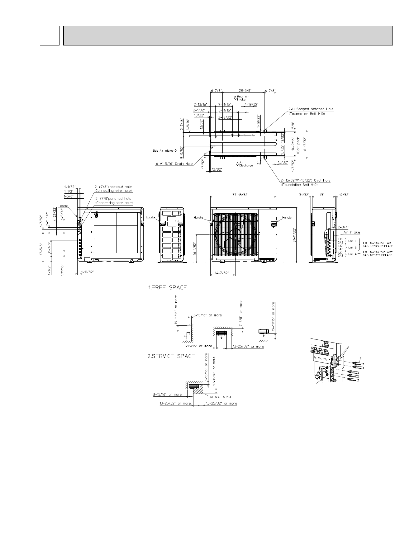
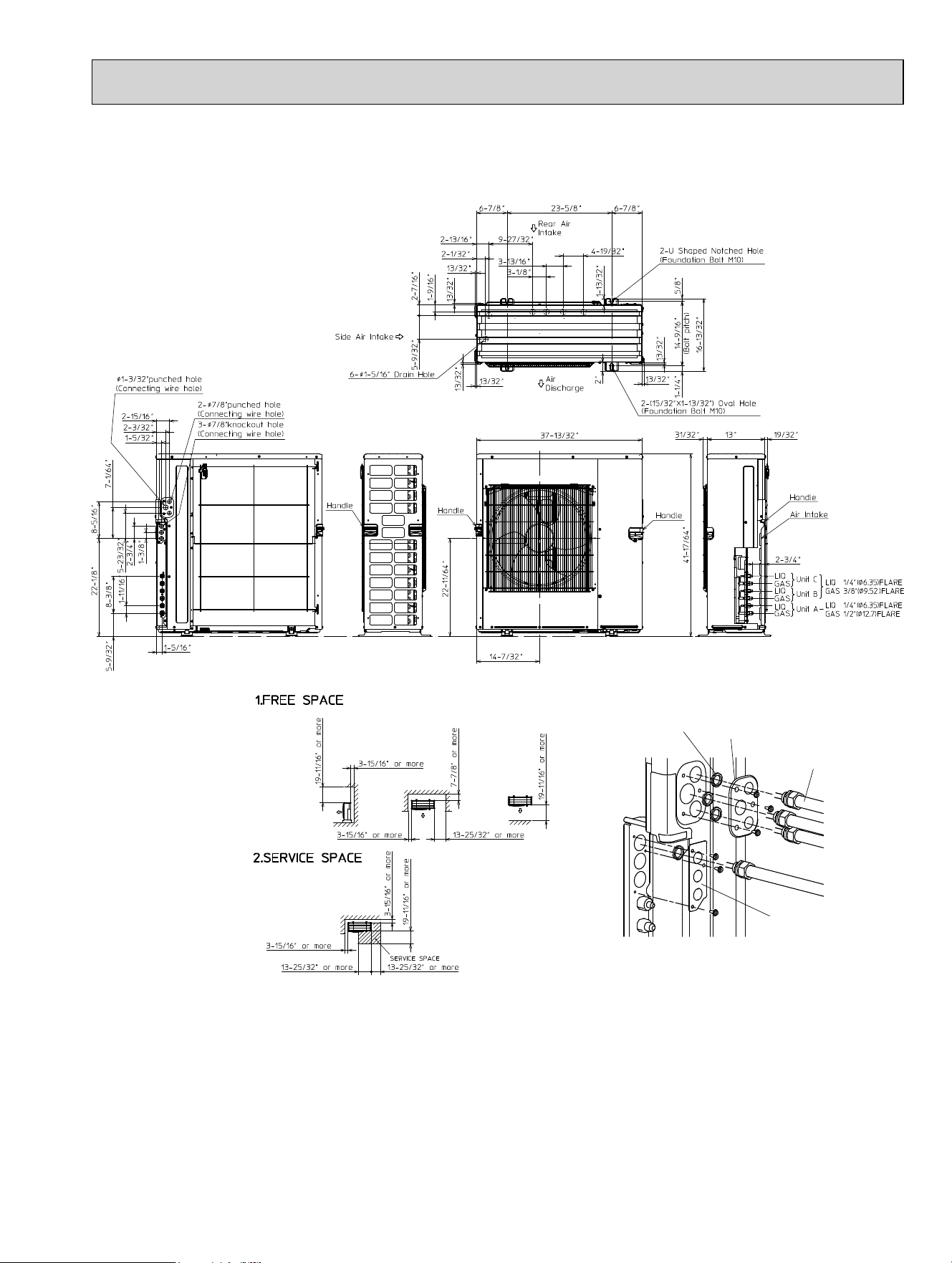
MXZ-3C24NA MXZ-3C24NA2
MXZ-3C30NA MXZ-3C30NA2
Unit: inch (mm)
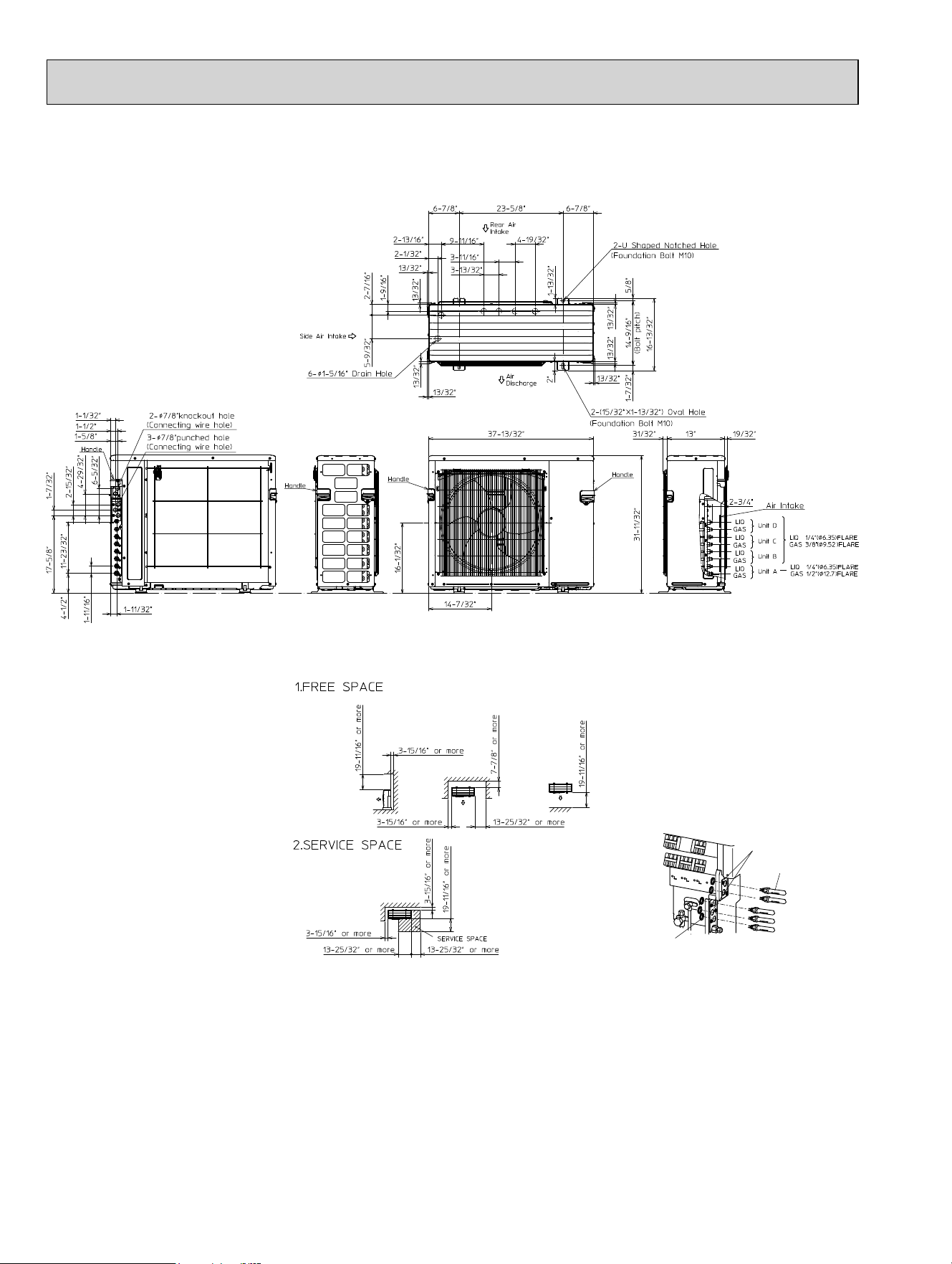
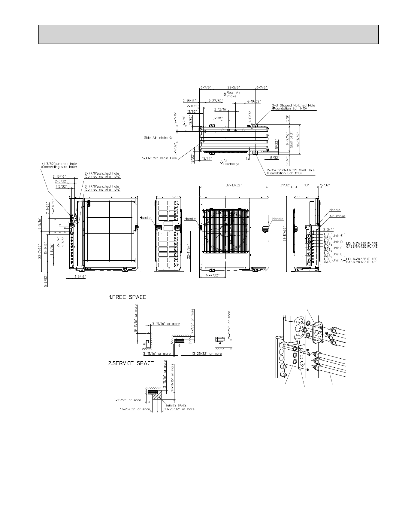
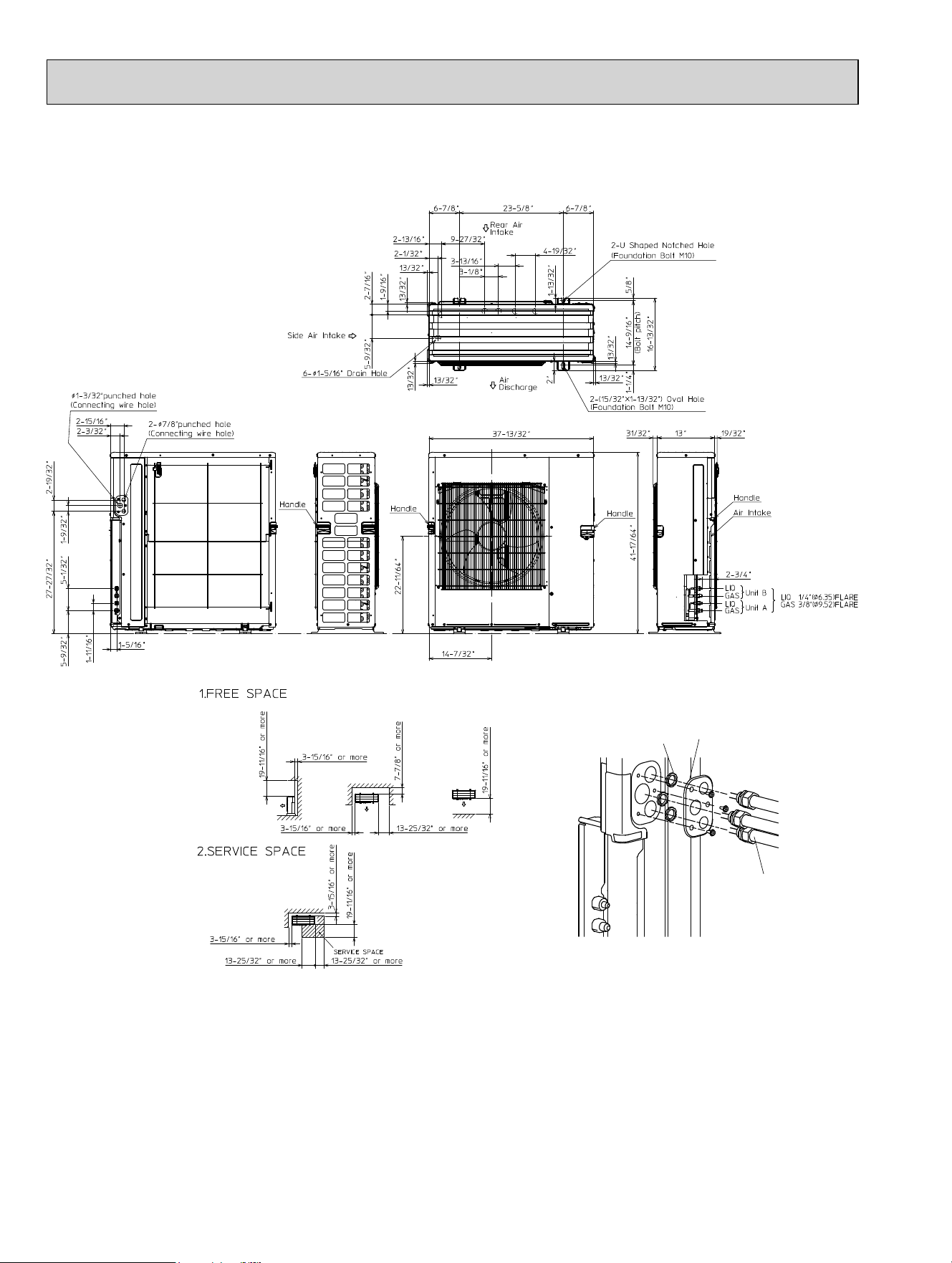
OUTLINES AND DIMENSIONS
5
Lock nut
Conduit plates
Conduit connector
OBH702C
16
MXZ-4C36NA MXZ-4C36NA2
Unit: inch (mm)
Lock nut
Conduit plates
Conduit connector
OBH702C
17
MXZ-5C42NA MXZ-5C42NA2
Unit: inch (mm)
Lock nut
Conduit
connector
Conduit plate Under
Conduit plate Top
OBH702C
18
MXZ-2C20NAHZ MXZ-2C20NAHZ2
Unit: inch (mm)
Lock
nut
Conduit connector
Conduit plate
OBH702C
19
MXZ-3C24NAHZ MXZ-3C24NAHZ2
MXZ-3C30NAHZ MXZ-3C30NAHZ2
Unit: inch (mm)
Lock
nut
Conduit connector
Conduit
plate
Under
Conduit plate Top
OBH702C
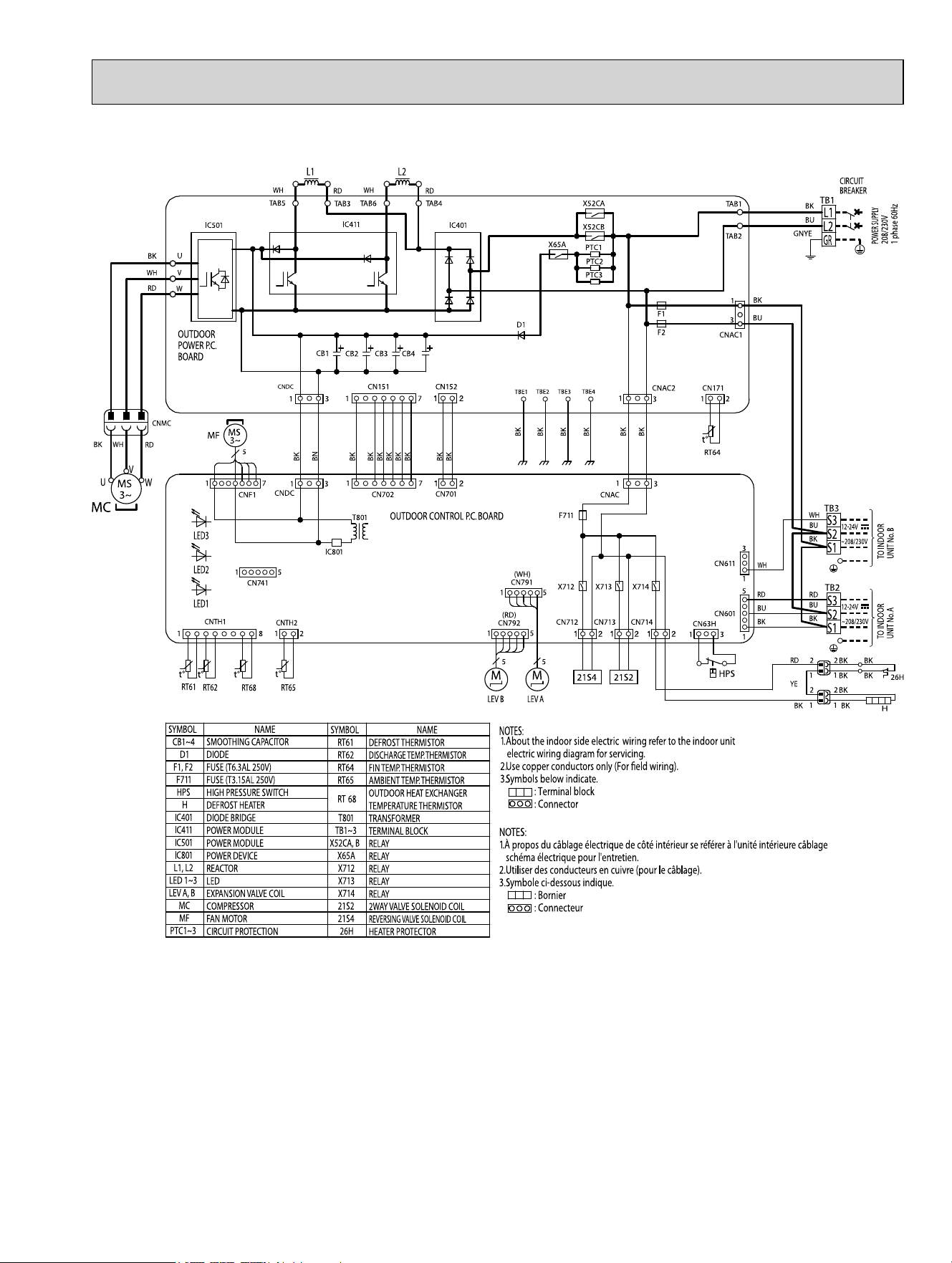
20
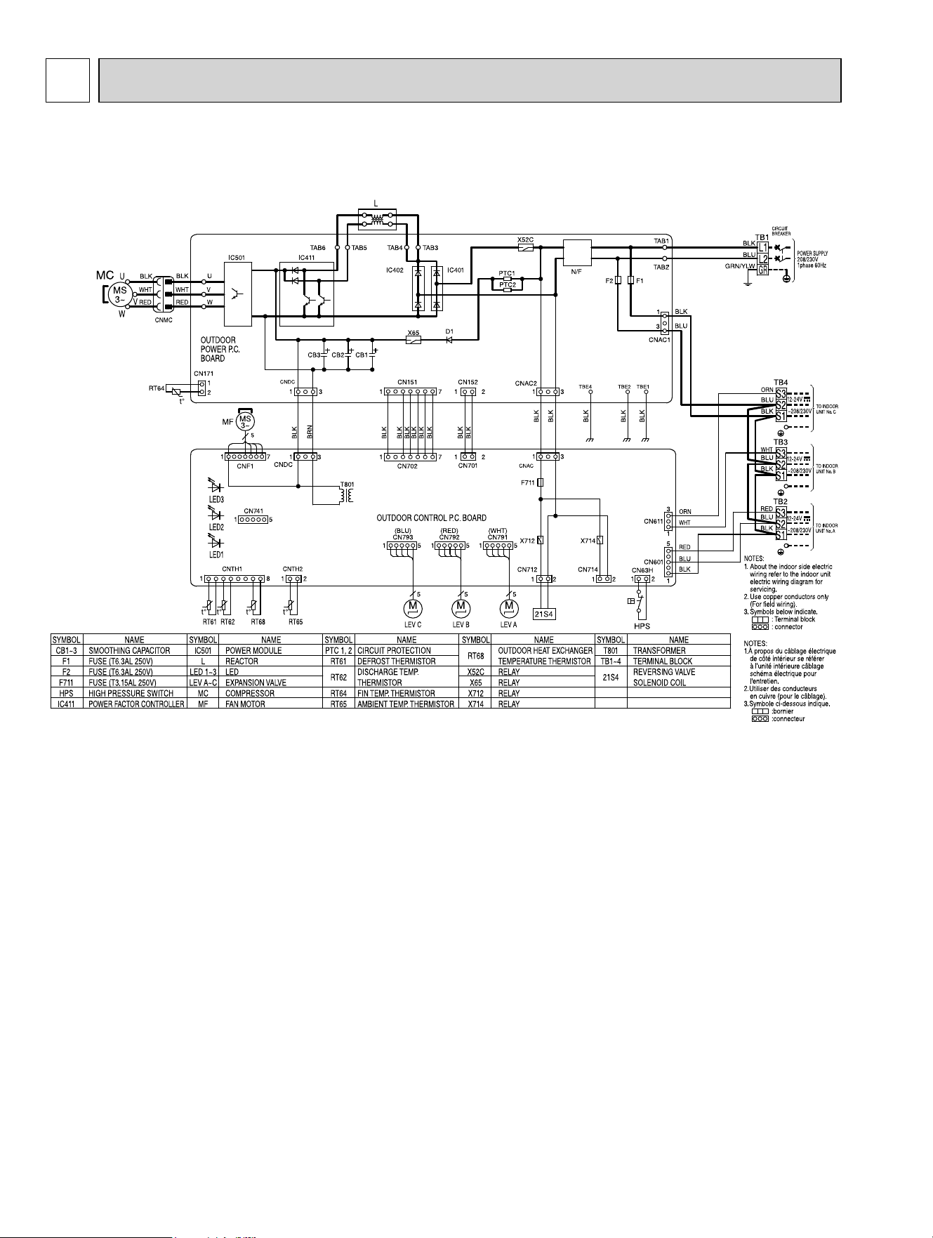
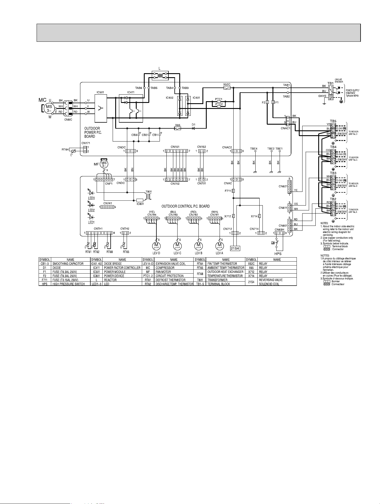
MXZ-3C24NA
MXZ-3C30NA
WIRING DIAGRAM
6
OBH702C
21
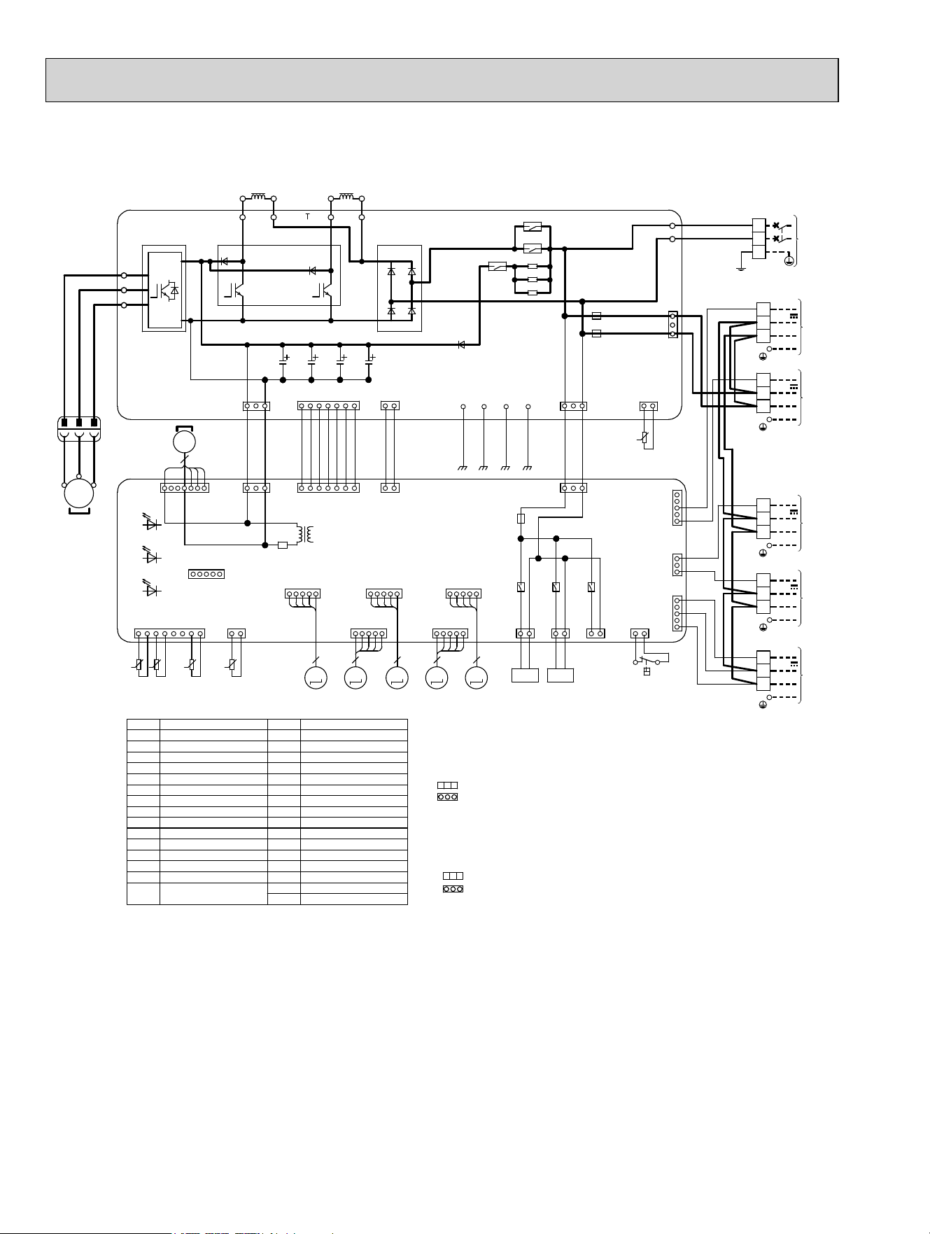
MXZ-3C24NA2
MXZ-3C30NA2
OBH702C
22
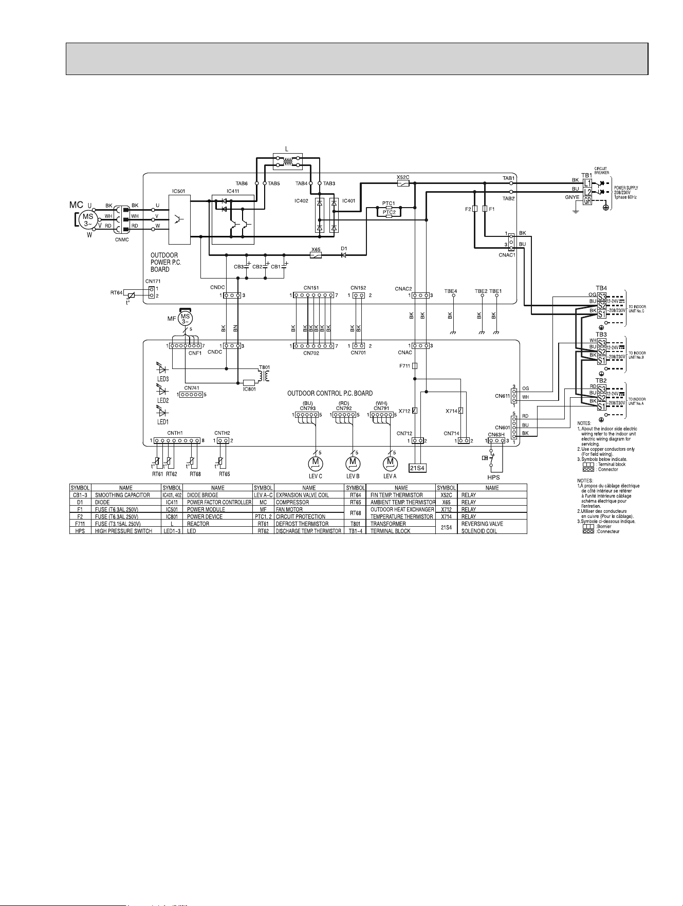
MXZ-4C36NA
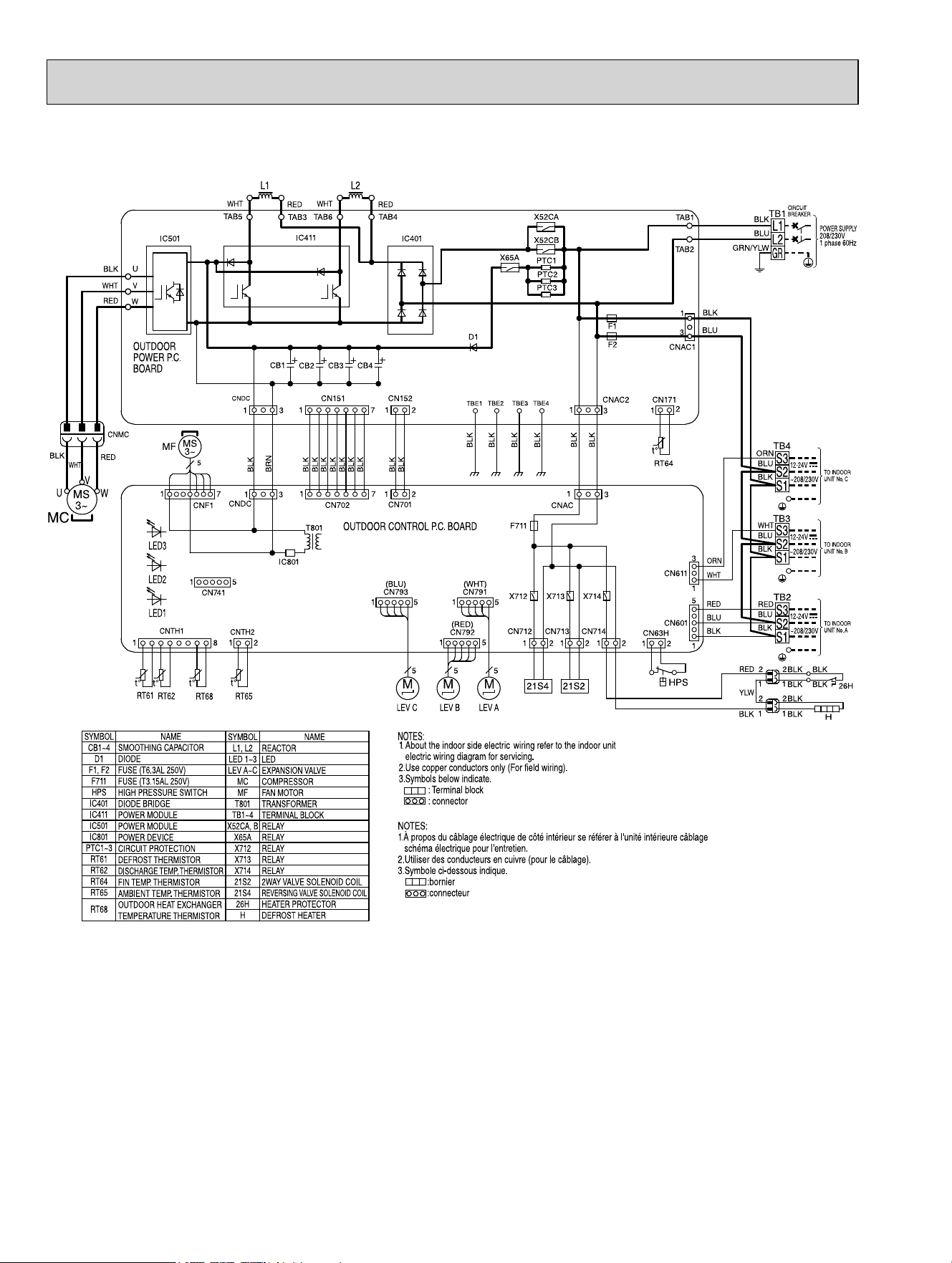
OBH702C
23
MXZ-4C36NA2
OBH702C
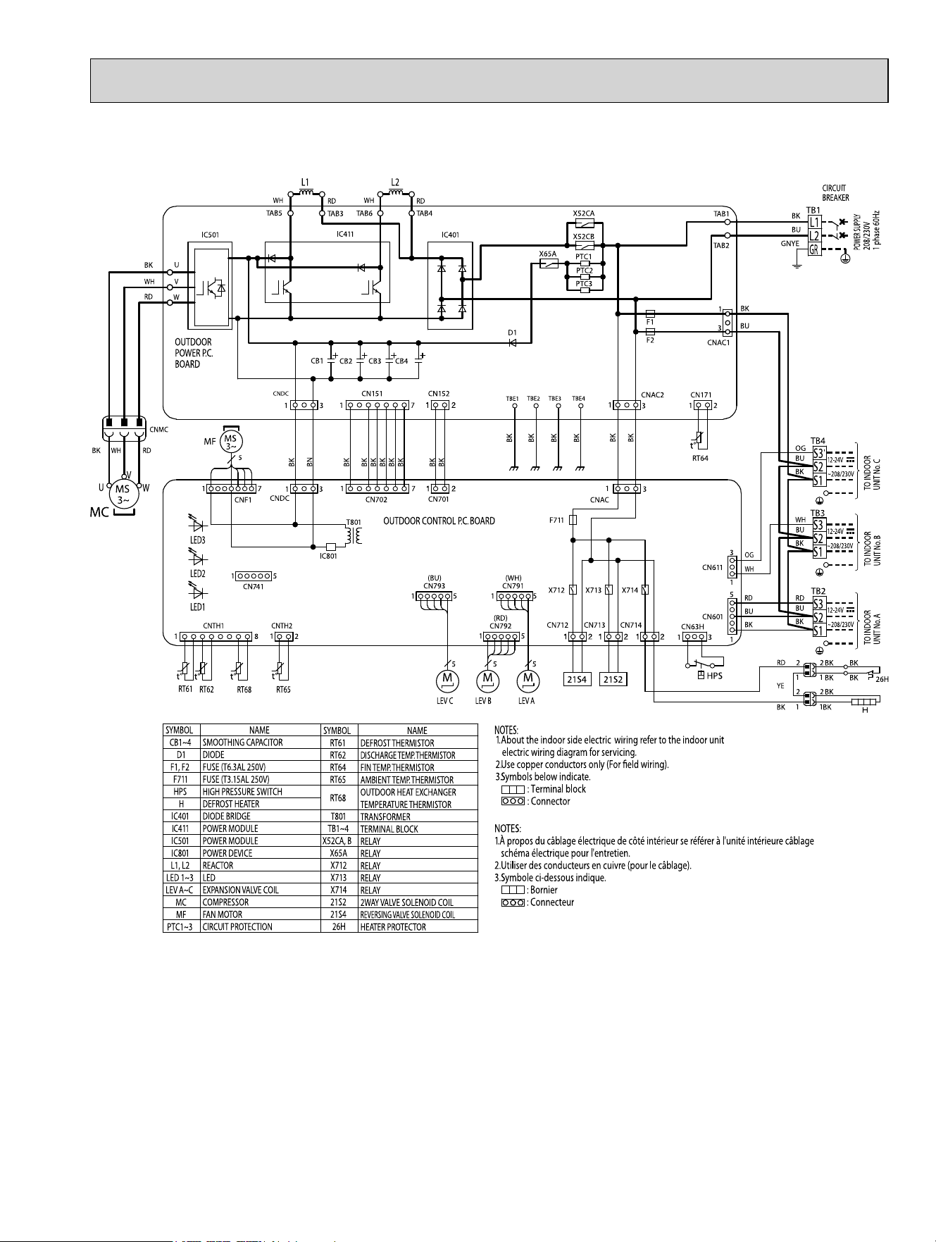
24
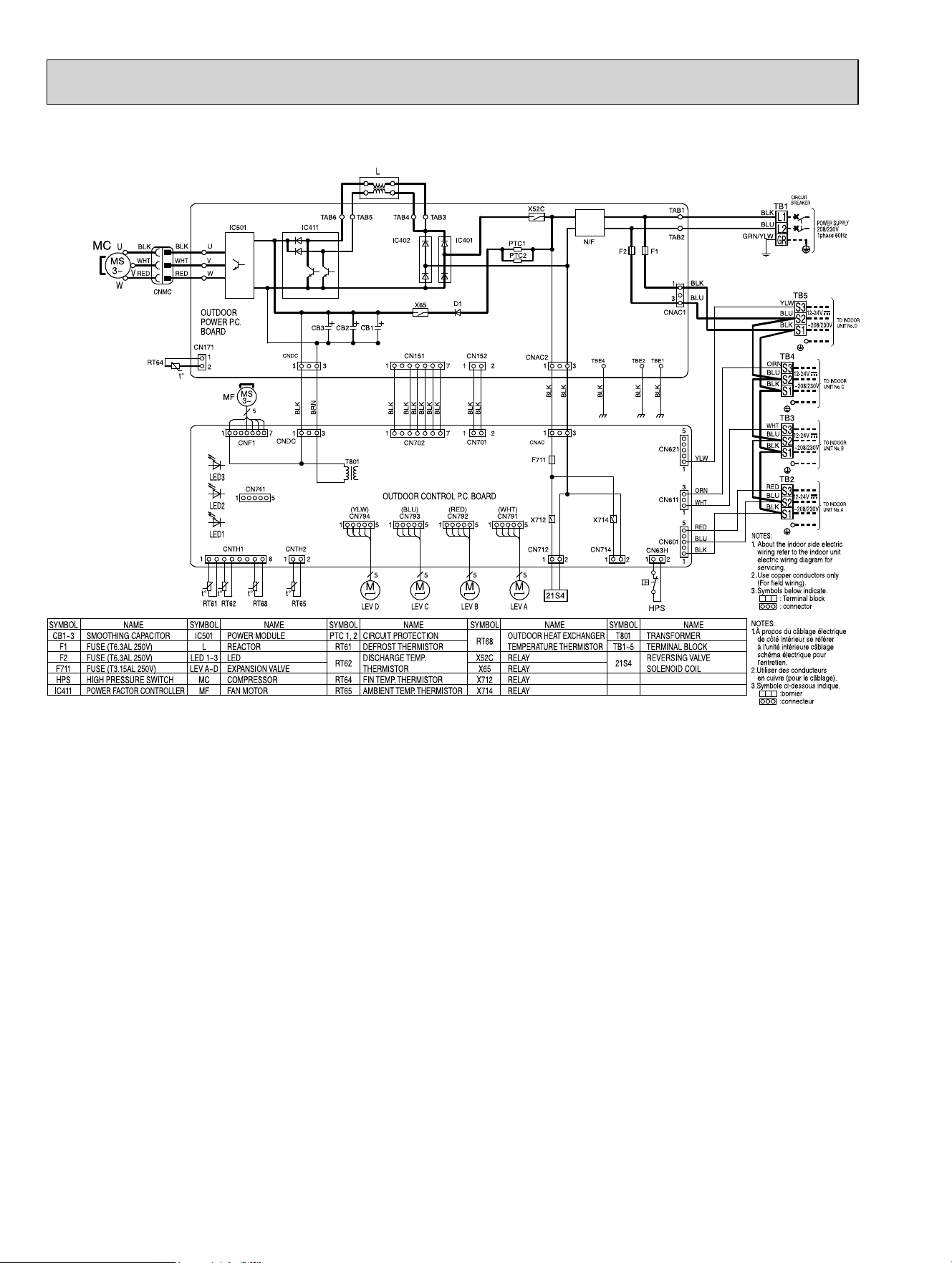
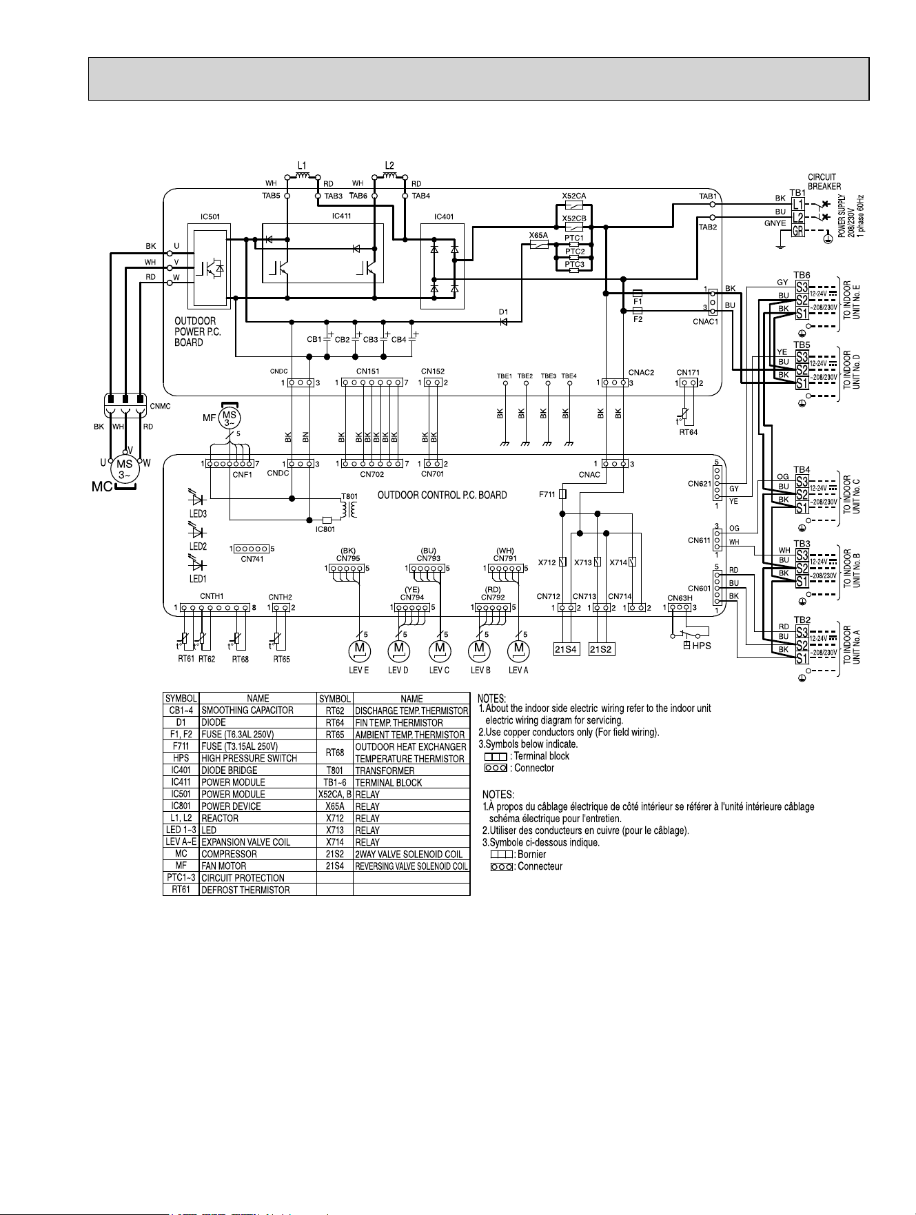
MXZ-5C42NA
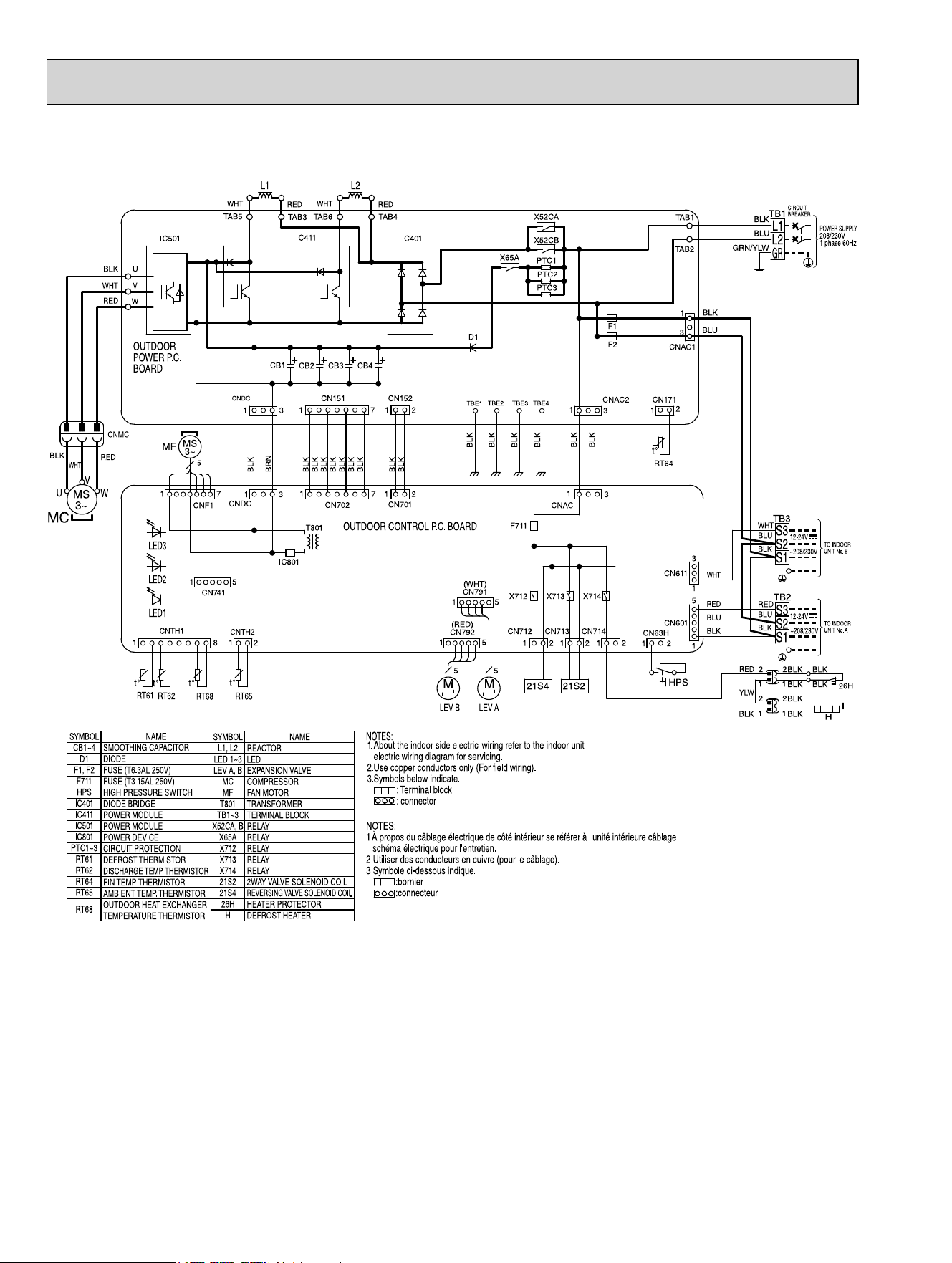
NOTES:
1.À propos du câblage électrique de côté intérieur se référer à l'unité intérieure câblage
schéma électrique pour l'entretien.
2.Utiliser des conducteurs en cuivre (pour le câblage).
3.Symbole ci-dessous indique.
:bornier
:connecteur
MC
U
V
W
CNMC
BLK
WHT
RED
BLK
RED
REDRED
WHT
WHT WHT
U
W
V
OUTDOOR
POWER P.C.
BOARD
t°
t°
t°
t°
CNTH2
CNTH1
RT61
RT62
RT68
RT65
1
8
1
2
LED2
LED1
LED3
IC501
CN171
RT64
t°
1
2
CN741
15
MF
17
5
CNF1
CNDC
BLK
BRN
13
13
CNDC
IC401
TAB3
TAB4
TAB5
TAB6
IC411
L1 L2
D1
X65A
CB3 CB4
CB2
CB1
X52CA
X52CB
PTC1
PTC2
PTC3
F1
F2
TAB2
TAB1
TB1
L1
L2
GR
BLK
BLU
GRN/YLW
BLK
BLU
CNAC1
1
3
CIRCUIT
BREAKER
POWER SUPPLY
208/230V
1 phase 60Hz
TB4
S2
S3
S1
ORN
BLU
BLK
12-24V
~208/230V
TO INDOOR
UNIT No. C
TB3
S2
S3
S1
WHT
BLU
BLK
12-24V
~208/230V
TO INDOOR
UNIT No. B
TB2
S2
S3
S1
RED
BLU
BLK
12-24V
~208/230V
TO INDOOR
UNIT No. A
CNAC2
BLK
BLK
CNAC
1
3
1
3
TBE4TBE2 TBE3
TBE1
BLK
BLK
BLK
BLK
CN151 CN152
BLK
BLK
BLK
BLK
BLK
BLK
BLK
BLK
BLK
2117
17
21
CN702
CN701
F711
T801
IC801
OUTDOOR CONTROL P.C. BOARD
(BLU)
CN793
(WHT)
CN791
1515
(RED)
CN792
15
X712 X714
CN712 CN714
21
21
X713
CN713
21
21S4 21S2
LEV C LEV B LEV A
555
MM
CN611
CN601
CN63H
21
1
5
1
3
ORN
GRY
YLW
WHT
RED
BLU
BLK
HPS
CN622
1
5
(YLW)
CN794
15
(BLK)
CN795
15
M
LEV D
5
M
LEV E
5
M
MS
3~
MS
3~
TB5
S2
S3
S1
YLW
BLU
BLK
12-24V
~208/230V
TO INDOOR
UNIT No. D
TB6
S2
S3
S1
GRY
BLU
BLK
12-24V
~208/230V
TO INDOOR
UNIT No. E
SYMBOL
CB1~4
D1
F1, F2
F711
HPS
IC401
IC411
IC501
IC801
PTC1~3
RT61
RT62
RT64
RT65
RT68
NAME
SMOOTHING CAPACITOR
DIODE
FUSE (T6.3AL 250V)
FUSE (T3.15AL 250V)
HIGH PRESSURE SWITCH
DIODE BRIDGE
POWER MODULE
POWER MODULE
POWER DEVICE
CIRCUIT PROTECTION
DEFROST THERMISTOR
DISCHARGE TEMP. THERMISTOR
FIN TEMP. THERMISTOR
AMBIENT TEMP. THERMISTOR
OUTDOOR HEAT EXCHANGER
TEMPERATURE THERMISTOR
SYMBOL
L1, L2
LED 1~3
LEV A~E
MC
MF
T801
TB1~6
X52CA, B
X65A
X712
X713
X714
21S2
21S4
NAME
REACTOR
LED
EXPANSION VALVE
COMPRESSOR
FAN MOTOR
TRANSFORMER
TERMINAL BLOCK
RELAY
RELAY
RELAY
RELAY
RELAY
2WAY VALVE SOLENOID COIL
REVERSING VALVE SOLENOID COIL
1.About the indoor side electric wiring refer to the indoor unit
electric wiring diagram for servicing.
2.Use copper conductors only (For field wiring).
3.Symbols below indicate.
: Terminal block
: connector
NOTES:
OBH702C
25
MXZ-5C42NA2
OBH702C
26
MXZ-2C20NAHZ
OBH702C
27
MXZ-2C20NAHZ2
OBH702C
28
MXZ-3C24NAHZ
MXZ-3C30NAHZ
OBH702C
29
MXZ-3C24NAHZ2
MXZ-3C30NAHZ2
OBH702C
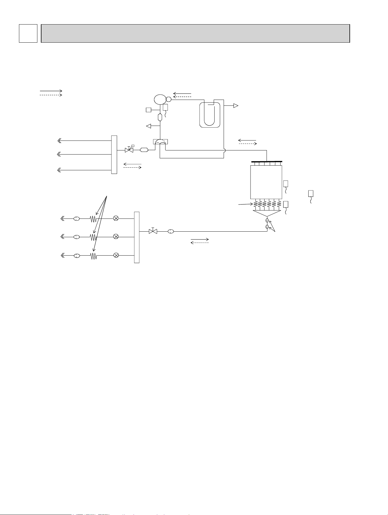
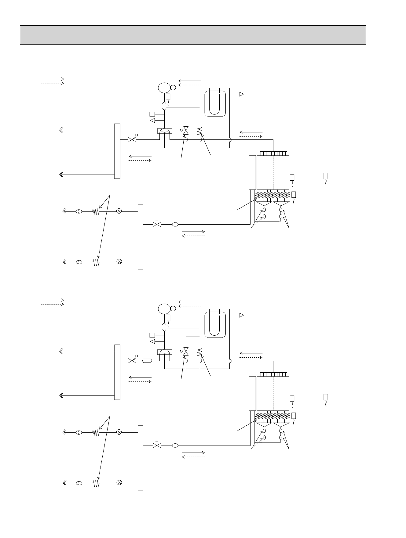
30
Unit: inch (mm)
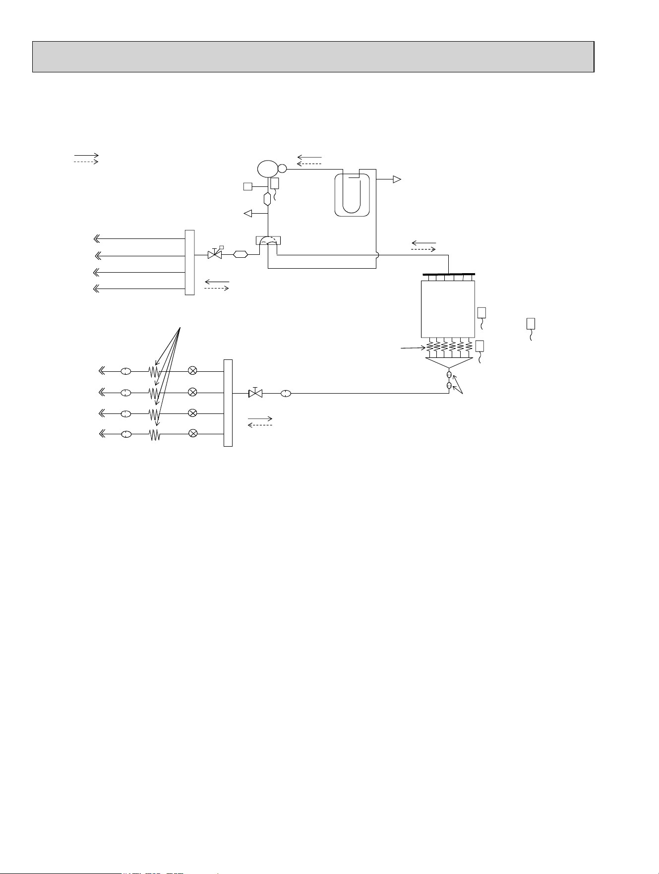
MXZ-3C24NA MXZ-3C24NA2
MXZ-3C30NA MXZ-3C30NA2
REFRIGERANT SYSTEM DIAGRAM
7
R.V.coil
OFF Refrigerant flow in heating
ON Refrigerant flow in cooling
Outdoor
heat exchanger
Compressor
Muffler
4-way valve
High pressure switch
ĭ1/4
ĭ3/8
Indoor unit B
ĭ1/2
Indoor unit A
Accumulator
Indoor unit C
ĭ1/4
LEVA
Distributor
Stop valve
(with service port)
Capillary tube
Capillary tube
O.D.0.16 x I.D.0.11 x 3.94
(Ø4.0 x Ø2.8 x 100)
Strainer
#100
Union
Union
Header(Gas)
Stop valve
Strainer
#100
Header (Evaporator)
Service port
ĭ1/4
ĭ3/8
Sub
muffler
Ambient
temperature
thermistor
RT65
Outdoor
heat exchanger temperature
thermistor
RT68
Compressor shell
temperature
thermistor
RT62
Defrost
temperature
thermistor
RT61
Indoor unit B
Indoor unit A
Indoor unit C
Service port
Strainer
#100
Strainer
#100
LEVB
LEVC
Strainer
#50
OBH702C

31
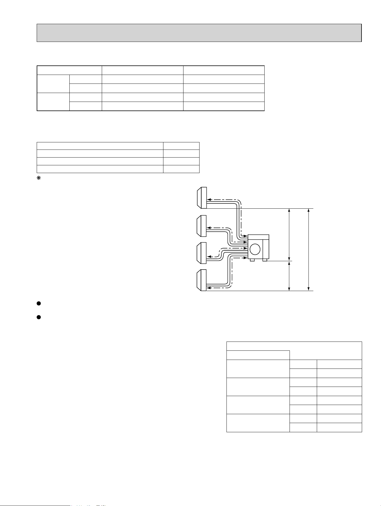
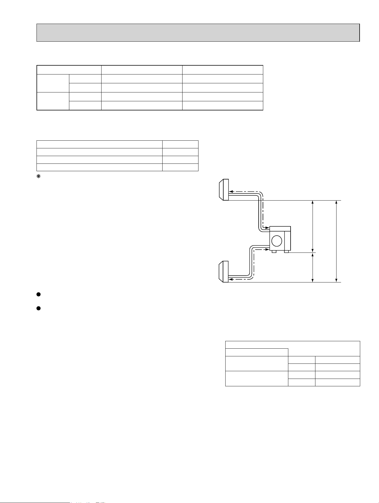
Refrigerant pipe diameter is different according to indoor unit to be connected. When using extension pipes, refer to the
tables below.
When the diameter of refrigerant pipe is different from that of outdoor unit union, use optional Different-diameter pipe.
For further information on Different-diameter pipe, refer to "PARTS CATALOG".
Unit: inch
Piping length each indoor unit (a, b, c) 82 ft. MAX.
Total piping length (a+b+c) 230 ft. MAX.
Bending point for each unit 25 MAX.
Total bending point 70 MAX.
It is irrelevant which unit is higher.
MAX. REFRIGERANT PIPING LENGTH & PIPE SIZE SELECTION
MXZ-3C24NA MXZ-3C30NA MXZ-3C24NA2 MXZ-3C30NA2
Operating Range MXZ-3C24NA MXZ-3C30NA MXZ-3C24NA2 MXZ-3C30NA2
a
b
Outdoor
unit
Indoor
units
Max. height difference
49 ft.
49 ft.
c
49 ft.
Outdoor unit union diameter
For
Indoor unit A
Liquid 1/4
Gas 1/2
Indoor unit B
Liquid 1/4
Gas 3/8
Indoor unit C
Liquid 1/4
Gas 3/8
Indoor intake air temperature Outdoor intake air temperature
Cooling
Maximum 95°FDB, 71°FWB 115°FDB
Minimum 67°FDB, 57°FWB 14°FDB
Heating
Maximum 80°FDB, 67°FWB 75°FDB, 65°FWB
Minimum 70°FDB, 60°FWB 6°FDB, 5°FWB
OBH702C
32
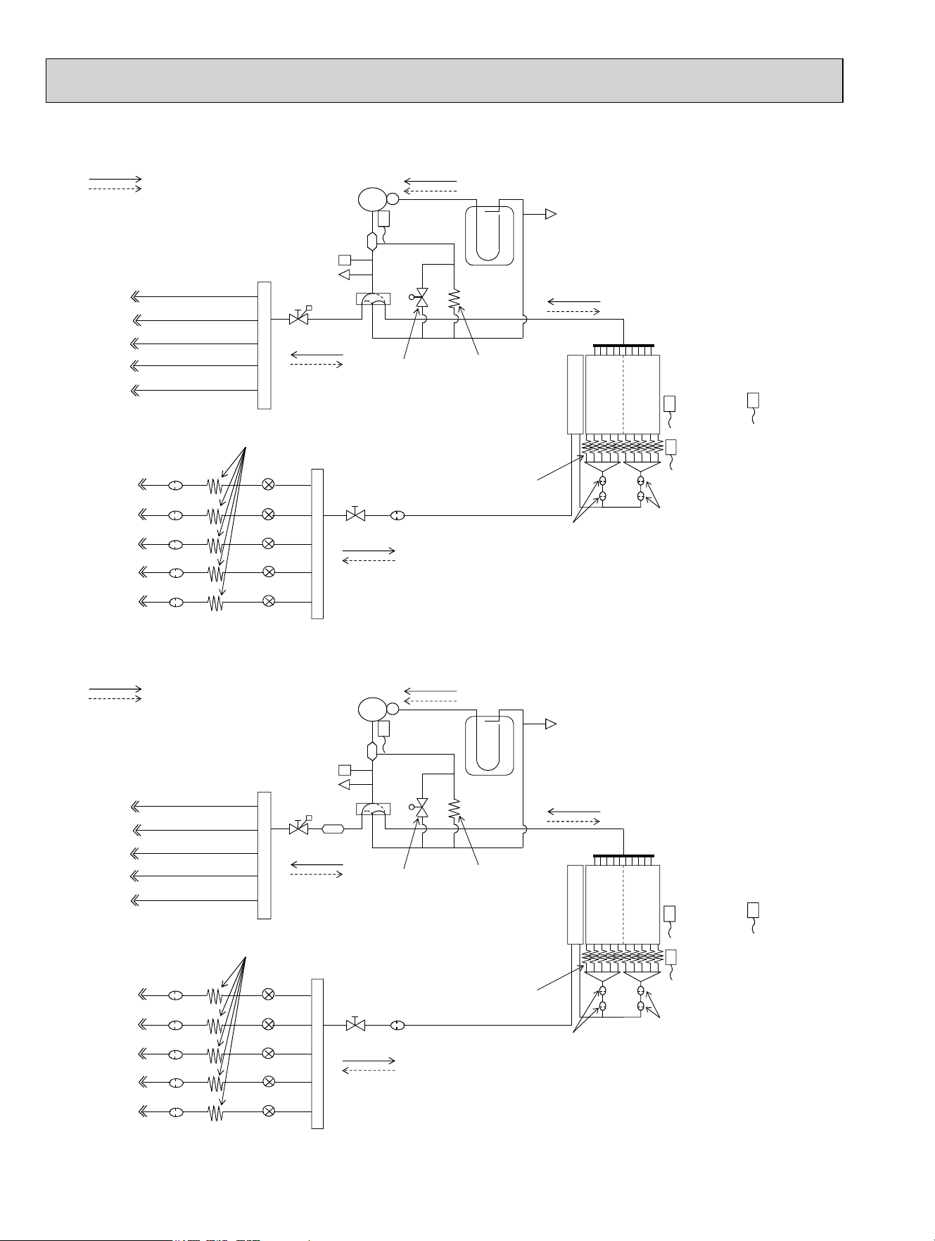
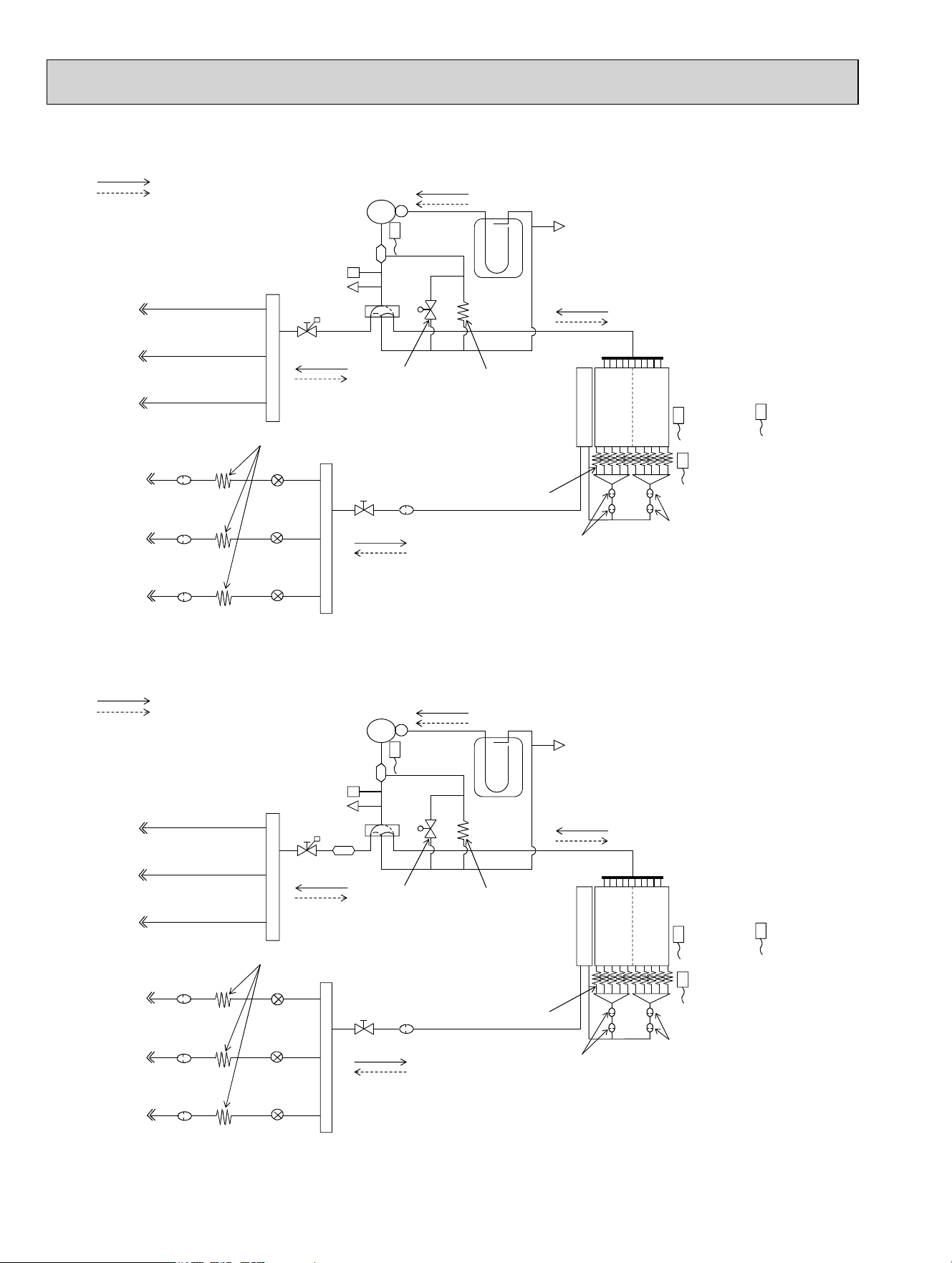
MXZ-4C36NA MXZ-4C36NA2
R.V.coil
OFF Refrigerant flow in heating
ON Refrigerant flow in cooling
Compressor
Muffler
High pressure switch
ĭ1/4
ĭ1/4
ĭ3/8
ĭ1/2
Accumulator
ĭ1/4
LEV A
ĭ3/8
Strainer
#100
Strainer
#100
Strainer
#100
Strainer
#100
Union
Union
Header(Gas)
Stop valve
Header (Evaporator)
ĭ1/4
ĭ3/8
Sub
muffler
Compressor shell
temperature
thermistor
RT62
Outdoor
heat exchanger
temperature
thermistor
RT68
Ambient
temperature
thermistor
RT65
Defrost
temperature
thermistor
RT61
Capillary tube
O.D.0.16 x I.D.0.11 x 3.94
(Ø4.0 x Ø2.8 x 100)
Indoor unit A
Indoor unit D
Indoor unit C
Indoor unit B
4-way valve
Service port
Service port
Stop valve
(with service port)
Indoor unit A
Indoor unit D
Indoor unit C
Indoor unit B
LE
V B
LEV C
LEV D
Outdoor
heat exchanger
Capillary tube
Distributor
Strainer
#100
Strainer
#50
Unit: inch (mm)
OBH702C
33
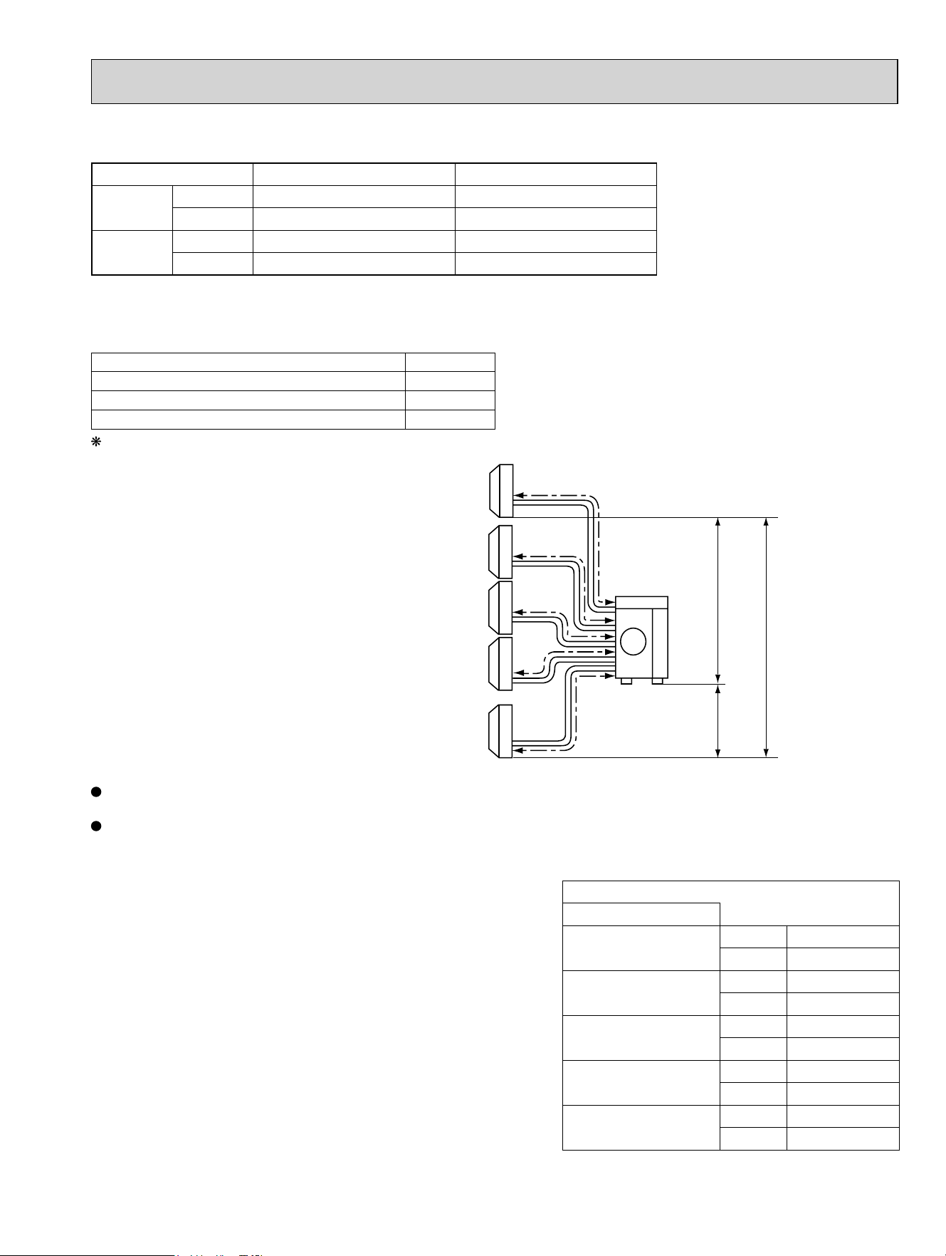
Refrigerant pipe diameter is different according to indoor unit to be connected. When using extension pipes, refer to the
tables below.
When the diameter of refrigerant pipe is different from that of outdoor unit union, use optional Different-diameter pipe.
For further information on Different-diameter pipe, refer to "PARTS CATALOG".
Unit: inch
Piping length each indoor unit (a, b, c, d) 82 ft. MAX.
Total piping length (a+b+c+d) 230 ft. MAX.
Bending point for each unit 25 MAX.
Total bending point 70 MAX.
It is irrelevant which unit is higher.
MAX. REFRIGERANT PIPING LENGTH & PIPE SIZE SELECTION
MXZ-4C36NA MXZ-4C36NA2
Operating Range MXZ-4C36NA MXZ-4C36NA2
a
b
c
d
Outdoor
unit
Indoor
units
49 ft.
49 ft.
49 ft.
Max. height difference
Outdoor unit union diameter
For
Indoor unit A
Liquid 1/4
Gas 1/2
Indoor unit B
Liquid 1/4
Gas 3/8
Indoor unit C
Liquid 1/4
Gas 3/8
Indoor unit D
Liquid 1/4
Gas 3/8
Indoor intake air temperature Outdoor intake air temperature
Cooling
Maximum 95°FDB, 71°FWB 115°FDB
Minimum 67°FDB, 57°FWB 14°FDB
Heating
Maximum 80°FDB, 67°FWB 75°FDB, 65°FWB
Minimum 70°FDB, 60°FWB 6°FDB, 5°FWB
OBH702C
34
MXZ-5C42NA
MXZ-5C42NA2
R.V.coil
OFF Refrigerant flow in heating
ON Refrigerant flow in cooling
Compressor
Oil separator
High pressure switch
Ø1/4
Ø1/4
Ø3/8
Ø1/2
Indoor unit A
Accumulator
Ø1/4
LEV A
Ø3/8
2-way
solenoid valve
Distributor
Strainer #100
Union
Union
Header(Gas)
Stop valve
Strainer
Strainer
#50
Strainer
#50
#100
Header(Evaporator)
Capillary tube
Capillary tube
O.D.0.10 x I.D.0.02 x 39.37
(Ø2.5 x Ø0.6 x 1000)
Ø1/4
Ø1/4
Ø3/8
Ø3/8
Compressor shell
temperature
thermistor RT62
Outdoor
heat exchanger
temperature
thermistor
RT68
Ambient
temperature
thermistor
RT65
Defrost
temperature
thermistor
RT61
Capillary tube
O.D.0.16 x I.D.0.11 x 3.94
(Ø4.0 x Ø2.8 x 100)
Outdoor
heat exchanger
4-way valve
Stop valve
(with service port)
Service port
Service port
Indoor unit B
Indoor unit C
Indoor unit D
Indoor unit E
Indoor unit A
Indoor unit B
Indoor unit C
Indoor unit D
Indoor unit E
Strainer #100
Strainer #100
Strainer #100
Strainer #100 LEV B
LEV E
LEV D
LEV C
R.V.coil
OFF Refrigerant flow in heating
ON Refrigerant flow in cooling
Compressor
Oil separator
High pressure switch
Ø1/4
Ø1/4
Ø3/8
Ø1/2
Indoor unit A
Accumulator
Ø1/4
LEV A
Ø3/8
2-way
solenoid valve
Sub
muffler
Distributor
Strainer #100
Union
Union
Header(Gas)
Stop valve
Strainer
Strainer
#50
Strainer
#50
#100
Header(Evaporator)
Capillary tube
Capillary tube
O.D.0.10 x I.D.0.02 x 39.37
(Ø2.5 x Ø0.6 x 1000)
Ø1/4
Ø1/4
Ø3/8
Ø3/8
Compressor shell
temperature
thermistor RT62
Outdoor
heat exchanger
temperature
thermistor
RT68
Ambient
temperature
thermistor
RT65
Defrost
temperature
thermistor
RT61
Capillary tube
O.D.0.16 x I.D.0.11 x 3.94
(Ø4.0 x Ø2.8 x 100)
Outdoor
heat exchanger
4-way
valve
Stop valve
(with service port)
Service port
Service port
Indoor unit B
Indoor unit C
Indoor unit D
Indoor unit E
Indoor unit A
Indoor unit B
Indoor unit C
Indoor unit D
Indoor unit E
Strainer #100
Strainer #100
Strainer #100
Strainer #100 LEV B
LEV E
LEV D
LEV C
Unit: inch (mm)
OBH702C
35
Refrigerant pipe diameter is different according to indoor unit to be connected. When using extension pipes, refer to the
tables below.
When diameter of refrigerant pipe is different from that of outdoor unit union, use optional Different-diameter pipe.
For further information on Different-diameter pipe, refer to "PARTS CATALOG".
Outdoor unit union diameter
For
Indoor unit A
Liquid 1/4
Gas 1/2
Indoor unit B
Liquid 1/4
Gas 3/8
Indoor unit C
Liquid 1/4
Gas 3/8
Indoor unit D
Liquid 1/4
Gas 3/8
Indoor unit E
Liquid 1/4
Gas 3/8
Operating Range MXZ-5C42NA MXZ-5C42NA2
Piping length each indoor unit (a, b, c, d, e) 82 ft. MAX.
Total piping length (a+b+c+d+e) 262 ft. MAX.
Bending point for each unit 25 MAX.
Total bending point 80 MAX.
It is irrelevant which unit is higher.
MAX. REFRIGERANT PIPING LENGTH & PIPE SIZE SELECTION
MXZ-5C42NA MXZ-5C42NA2
Unit: inch
a
b
e
c
d
Outdoor
unit
Indoor
units
49 ft.
49 ft.
49 ft.
Max. height difference
Indoor intake air temperature Outdoor intake air temperature
Cooling
Maximum 95°FDB, 71°FWB 115°FDB
Minimum 67°FDB, 57°FWB 14°FDB
Heating
Maximum 80°FDB, 67°FWB 75°FDB, 65°FWB
Minimum 70°FDB, 60°FWB 6°FDB, 5°FWB
OBH702C
36
MXZ-2C20NAHZ
MXZ-2C20NAHZ2
R.V.coil
OFF Refrigerant flow in heating
ON Refrigerant flow in cooling
Compressor
Oil separator
High pressure switch
Ø3/8
Ø3/8
Accumulator
Ø1/4
LEV A
2-way
solenoid valve
Distributor
Strainer
#100
Union
Union
Header(Gas)
Stop valve
Strainer
#100
Header(Evaporator)
Ø1/4
Outdoor
heat exchanger
temperature
thermistor
RT68
Ambient
temperature
thermistor
RT65
Defrost
temperature
thermistor
RT61
Compressor shell
temperature
thermistor RT62
Capillary tube
Capillary tube
O.D.0.10 x I.D.0.02 x 39.37
(Ø2.5 x Ø0.6 x 1000)
Capillary tube
O.D.0.16 x I.D.0.11 x 3.94
(Ø4.0 x Ø2.8 x 100)
4-way valve
Stop valve
(with service port)
Service port
Service port
Outdoor
heat exchanger
Indoor unit A
Indoor unit
B
Indoor unit A
Indoor unit B
Strainer
#100
LEV B
Strainer
#50
Strainer
#50
R.V.coil
OFF Refrigerant flow in heating
ON Refrigerant flow in cooling
Compressor
Oil separator
High pressure switch
Ø
Sub
muffler
4-way
valve
3/8
Ø3/8
Accumulator
Ø1/4
LEV A
2-way
solenoid valve
Distributor
Strainer
#100
Union
Union
Header(Gas)
Stop valve
Strainer
#100
Header(Evaporator)
Ø1/4
Outdoor
heat exchanger
temperature
thermistor
RT68
Ambient
temperature
thermistor
RT65
Defrost
temperature
thermistor
RT61
Compressor shell
temperature
thermistor RT62
Capillary tube
Capillary tube
O.D.0.10 x I.D.0.02 x 39.37
(Ø2.5 x Ø0.6 x 1000)
Capillary tube
O.D.0.16 x I.D.0.11 x 3.94
(Ø4.0 x Ø2.8 x 100)
Stop valve
(with service port)
Service port
Service port
Outdoor
heat exchanger
Indoor unit A
Indoor
unit B
Indoor unit A
Indoor unit B
Strainer
#100
LEV B
Strainer
#50
Strainer
#50
Unit: inch (mm)
OBH702C
37
Refrigerant pipe diameter is different according to indoor unit to be connected. When using extension pipes, refer to the
tables below.
When the diameter of refrigerant pipe is different from that of outdoor unit union, use optional Different-diameter pipe.
For further information on Different-diameter pipe, refer to "PARTS CATALOG".
Unit: inch
MAX. REFRIGERANT PIPING LENGTH & PIPE SIZE SELECTION
MXZ-2C20NAHZ MXZ-2C20NAHZ2
Operating Range MXZ-2C20NAHZ MXZ-2C20NAHZ2
Outdoor unit union diameter
For
Indoor unit A
Liquid 1/4
Gas 3/8
Indoor unit B
Liquid 1/4
Gas 3/8
Piping length each indoor unit (a, b) 82 ft. MAX.
Total piping length (a+b) 164 ft. MAX.
Bending point for each unit 25 MAX.
Total bending point 50 MAX.
It is irrelevant which unit is higher.
a
b
Outdoor
unit
Indoor
units
49 ft.
49 ft.
49 ft.
Max. height difference
Indoor intake air temperature Outdoor intake air temperature
Cooling
Maximum 95°FDB, 71°FWB 115°FDB
Minimum 67°FDB, 57°FWB 14°FDB
Heating
Maximum 80°FDB, 67°FWB 75°FDB, 65°FWB
Minimum 70°FDB, 60°FWB -12°FDB, -13°FWB
OBH702C
38
MXZ-3C24NAHZ MXZ-3C30NAHZ
MXZ-3C24NAHZ2 MXZ-3C30NAHZ2
R. V. coil
OFF Refrigerant flow in heating
ON Refrigerant flow in cooling
Compressor
Oil separator
High pressure switch
Ø1/4
Ø1/2
Accumulator
Ø1/4
LEV A
Ø3/8
2-way
solenoid valve
Distributor
Strainer
#100
Union
Union
Header(Gas)
Stop valve
Strainer
#100
Header(Evaporator)
Ø1/4
Ø3/8
Compressor shell
temperature
thermistor RT62
Outdoor
heat exchanger
temperature
thermistor
RT68
Ambient
temperature
thermistor
RT65
Defrost
temperature
thermistor
RT61
Capillary tube
O.D.0.16 x I.D.0.11 x 3.94
(Ø4.0 x Ø2.8 x 100)
Capillary tube
Capillary tube
O.D.0.10 x I.D.0.02 x 39.37
(Ø2.5 x Ø0.6 x 1000)
Indoor unit B
Indoor unit C
Indoor unit A
4-way valve
Stop valve
(with service port)
Service port
Service port
Outdoor
heat exchanger
Indoor unit B
Indoor unit C
Indoor unit A
Strainer
#100
Strainer
#100
LEV B
LEV C
Strainer
#50
Strainer
#50
R. V. coil
OFF Refrigerant flow in heating
ON Refrigerant flow in cooling
Compressor
Oil separator
High pressure switch
Ø1/4
Ø1/2
Accumulator
Ø1/4
LEV A
Ø3/8
2-way
solenoid valve
Distributor
Strainer
#100
Union
Union
Header(Gas)
Stop valve
Strainer
#100
Header(Evaporator)
Ø1/4
Ø3/8
Compressor shell
temperature
thermistor RT62
Outdoor
heat exchanger
temperature
thermistor
RT68
Ambient
temperature
thermistor
RT65
Defrost
temperature
thermistor
RT61
Capillary tube
O.D.0.16 x I.D.0.11 x 3.94
(Ø4.0 x Ø2.8 x 100)
Capillary tube
Capillary tube
O.D.0.10 x I.D.0.02 x 39.37
(Ø2.5 x Ø0.6 x 1000)
Indoor unit B
Indoor unit C
Indoor unit A
4-way
valve
Stop valve
(with service port)
Service port
Service port
Outdoor
heat exchanger
Indoor unit B
Indoor unit C
Indoor unit A
Strainer
#100
Strainer
#100
LEV B
LEV C
Strainer
#50
Strainer
#50
Sub
muffler
Unit: inch (mm)
OBH702C

39
Refrigerant pipe diameter is different according to indoor unit to be connected. When using extension pipes, refer to the
tables below.
When the diameter of refrigerant pipe is different from that of outdoor unit union, use optional Different-diameter pipe.
For further information on Different-diameter pipe, refer to "PARTS CATALOG".
Unit: inch
Piping length each indoor unit (a, b, c) 82 ft. MAX.
Total piping length (a+b+c) 230 ft. MAX.
Bending point for each unit 25 MAX.
Total bending point 70 MAX.
It is irrelevant which unit is higher.
MAX. REFRIGERANT PIPING LENGTH & PIPE SIZE SELECTION
MXZ-3C24NAHZ MXZ-3C30NAHZ MXZ-3C24NAHZ2 MXZ-3C30NAHZ2
Operating Range MXZ-3C24NAHZ MXZ-3C30NAHZ MXZ-3C24NAHZ2 MXZ-3C30NAHZ2
a
b
Outdoor
unit
Indoor
units
Max. height difference
49 ft.
49 ft.
c
49 ft.
Outdoor unit union diameter
For
Indoor unit A
Liquid 1/4
Gas 1/2
Indoor unit B
Liquid 1/4
Gas 3/8
Indoor unit C
Liquid 1/4
Gas 3/8
Indoor intake air temperature Outdoor intake air temperature
Cooling
Maximum 95°FDB, 71°FWB 115°FDB
Minimum 67°FDB, 57°FWB 14°FDB
Heating
Maximum 80°FDB, 67°FWB 75°FDB, 65°FWB
Minimum 70°FDB, 60°FWB -12°FDB, -13°FWB
OBH702C

40
When relocating or disposing of the air conditioner, pump down the system following the procedure below so that no refriger-
ant is released into the atmosphere.
1) Turn off the breaker.
2) Connect the gauge manifold valve to the service port of the stop valve on the gas pipe side of the outdoor unit.
3) Fully close the stop valve on the liquid pipe side of the outdoor unit.
4) Turn on the breaker.
5) Start the emergency COOL operation on all the indoor units.
6) When the pressure gauge shows 0.1 to 0 psi [Gauge] (0.05 to 0 MPa), fully close the stop valve on the gas pipe side
of the outdoor unit and stop the operation. (Refer to the indoor unit installation manual about the method for stopping
the operation.)
* If too much refrigerant has been added to the air conditioner system, the pressure may not drop to
0.1 to 0 psi [Gauge]
(0.05 to 0 MPa)
, or the protection function may operate due to the pressure increase in the high-pressure refrigerant cir-
cuit. If this occurs, use a refrigerant collecting device to collect all of the refrigerant in the system, and then recharge the
system with the correct amount of refrigerant after the indoor and outdoor units have been relocated.
7) Turn off the breaker. Remove the pressure gauge and the refrigerant piping.
When pumping down the refrigerant, stop the compressor before disconnecting the refrigerant pipes.
The compressor may burst and cause injury if any foreign substance, such as air, enters the pipes.
WARNING
PUMPING DOWN
OBH702C
41
DATA
8
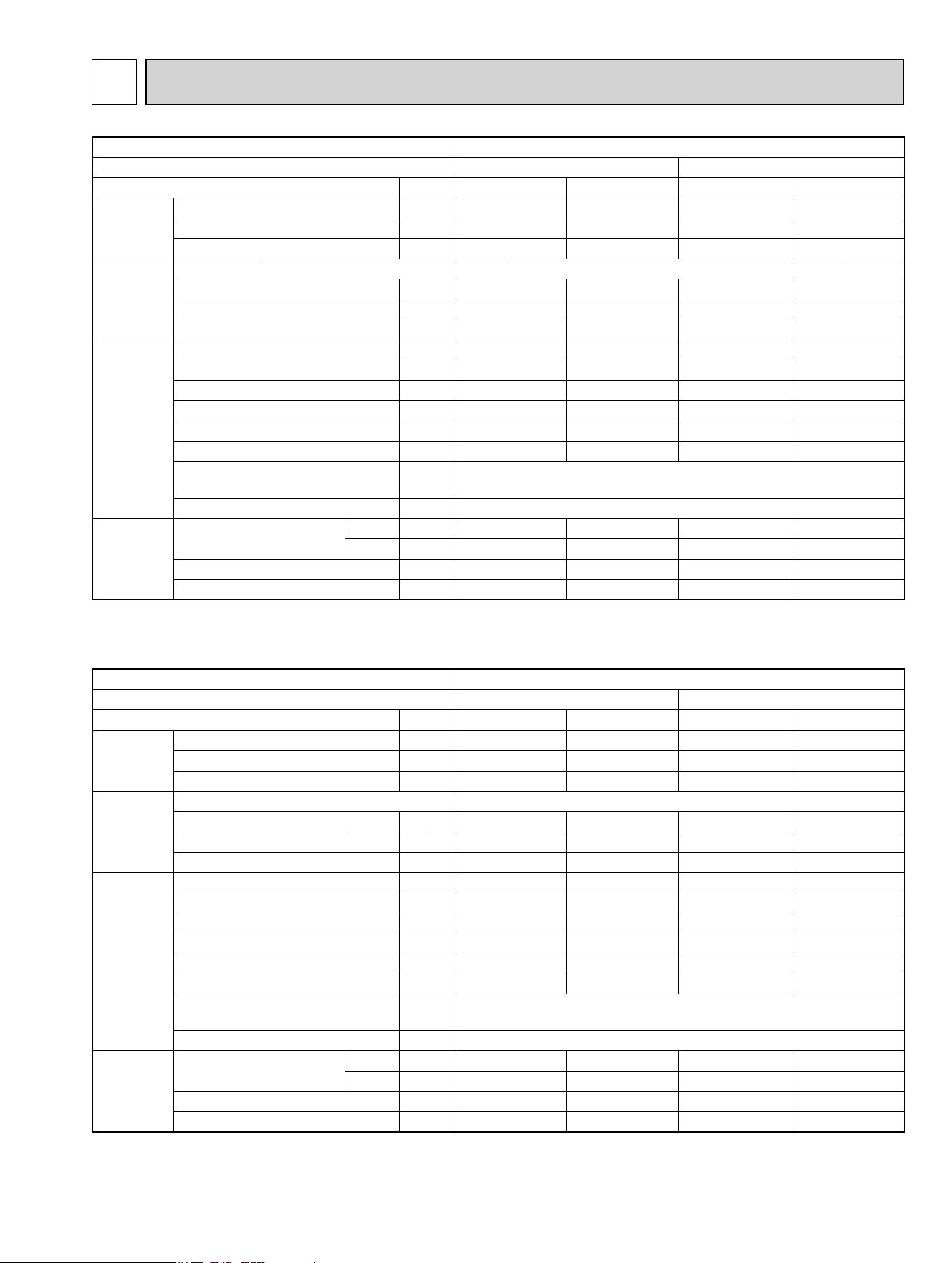
Model
MXZ-3C24NA MXZ-3C24NA2
Indoor type Non-Duct (06+06+09) Duct (09+09+09)
Item Unit Cooling Heating Cooling Heating
Total
Capacity Btu/h 22,000 25,000 23,600 24,600
SHF – – – – –
Input kW 1.62 1.75 2.10 1.90
Electrical
circuit
Power supply (V, phase, Hz) 208/230, 1, 60
Input kW 1.554 1.684 1.920 1.780
Comp. current (208/230V) A 7.47 / 6.76 8.1 / 7.32 9.23 / 8.35 8.56 / 7.74
Fan motor current A 0.3 0.3 0.3 0.3
Refrigerant
circuit
Condensing pressure PSIG 395 310 419 345
Suction pressure PSIG 162 101 138 102
Discharge temperature ºF 143 137 155 141
Condensing temperature ºF 116 98 120 106
Suction temperature ºF 59 36 50 34
Comp. shell bottom temp. ºF 137 128 146 131
Ref. pipe length
[Total pipe length for multi-system]
ft 25[75]
Refrigerant charge (R410A) – 6lb. 13 oz.
Outdoor
unit
Intake air temperature
DB ºF 95 47 95 47
WB ºF - 43 - 43
Fan speed rpm 720 750 720 750
Airfl ow CFM 2,287 2,382 2,287 2,382
Model
MXZ-3C30NA MXZ-3C30NA2
Indoor type Non-Duct (09+09+12) Duct (09+09+12)
Item Unit Cooling Heating Cooling Heating
Total
Capacity Btu/h 28,400 28,600 27,400 27,600
SHF – – – – –
Input kW 2.68 2.15 2.84 2.22
Electrical
circuit
Power supply (V, phase, Hz) 208/230, 1, 60
Input kW 2.614 2.084 2.650 2.090
Comp. current (208/230V) A 12.57 / 11.37 10.02 / 9.06 12.74 / 11.52 10.05 / 9.09
Fan motor current A 0.3 0.3 0.3 0.3
Refrigerant
circuit
Condensing pressure PSIG 432 323 439 323
Suction pressure PSIG 137 97 132 99
Discharge temperature ºF 159 136 165 136
Condensing temperature ºF 122 101 124 101
Suction temperature ºF 49 32 47 32
Comp. shell bottom temp. ºF 145 121 156 128
Ref. pipe length
[Total pipe length for multi-system]
ft 25[75]
Refrigerant charge (R410A) – 6 lb.13 oz.
Outdoor
unit
Intake air temperature
DB ºF 95 47 95 47
WB ºF - 43 - 43
Fan speed rpm 720 750 720 750
Airfl ow CFM 2,287 2,382 2,287 2,382
OBH702C
42
Model
MXZ-4C36NA MXZ-4C36NA2
Indoor type Non-Duct (09+09+09+09) Duct (09+09+09+09)
Item Unit Cooling Heating Cooling Heating
Total
Capacity Btu/h 35,400 36,000 34,400 34,400
SHF – – – – –
Input kW 3.76 3.02 3.94 3.10
Electrical
circuit
Power supply (V, phase, Hz) 208/230, 1, 60
Input kW 3.672 2.932 3.700 2.940
Comp. current (208/230V) A 17.65 / 15.97 14.1 / 12.75 17.79 / 16.09 14.13 / 12.78
Fan motor current A 0.3 0.3 0.3 0.3
Refrigerant
circuit
Condensing pressure PSIG 461 297 470 334
Suction pressure PSIG 141 89 129 91
Discharge temperature ºF 172 138 176 147
Condensing temperature ºF 127 95 129 103
Suction temperature ºF 51 28 46 29
Comp. shell bottom temp. ºF 162 130 165 139
Ref. pipe length
[Total pipe length for multi-system]
ft 25[100]
Refrigerant charge (R410A) – 6 lb.13 oz.
Outdoor
unit
Intake air temperature
DB ºF 95 47 95 47
WB ºF - 43 - 43
Fan speed rpm 720 750 720 750
Airfl ow CFM 2,287 2,382 2,287 2,382
OBH702C
43
Model
MXZ-2C20NAHZ MXZ-2C20NAHZ2
Indoor type Non-Duct (09+09) Duct (09+12)
Item Unit Cooling Heating Cooling Heating
Total
Capacity Btu/h 18,000 22,000 20,000 22,000
SHF -----
Input kW 1.34 1.62 1.82 1.75
Electrical
circuit
Power supply (V, phase, Hz) 208/230, 1, 60
Input kW 1.296 1.574 1.670 1.660
Comp. current (208/230V) A
6.23/5.63 7.57/6.84 8.03/7.26 7.98/7.22
Fan motor current A 0.43/0.39 0.43/0.39 0.43/0.39 0.43/0.39
Refrigerant
circuit
Condensing pressure PSIG 406 341 406 334
Suction pressure PSIG 154 110 133 113
Discharge temperature ºF 158 131 148 141
Condensing temperature ºF 108 105 112 103
Suction temperature ºF 60 37 46 37
Comp. shell bottom temp. ºF 137 107 127 117
Ref. pipe length
[Total pipe length for multi-system]
ft 25 [50]
Refrigerant charge (R410A) - 8 lb. 13 oz.
Outdoor
unit
Intake air temperature
DB ºF 95 47 95 47
WB ºF - 43 - 43
Fan speed rpm 630 730 630 730
Airfl ow CFM
2,118 2,542 2,118 2,542
Model
MXZ-5C42NA MXZ-5C42NA2
Indoor type Non-Duct (06+09+09+09+09) Duct (09+09+09+09+09)
Item Unit Cooling Heating Cooling Heating
Total
Capacity Btu/h 40,500 45,000 37,500 41,000
SHF - - - - -
Input kW 4.41 3.58 4.17 3.47
Electrical
circuit
Power supply (V, phase, Hz) 208/230, 1, 60
Input kW 4.300 3.465 3.870 3.270
Comp. current (208/230V) A
20.67/18.7 16.66/15.07 18.61/16.83 15.72/14.22
Fan motor current A 0.43/0.39 0.43/0.39 0.43/0.39 0.43/0.39
Refrigerant
circuit
Condensing pressure PSIG 466 305 446 326
Suction pressure PSIG 153 93 137 98
Discharge temperature ºF 172 155 165 143
Condensing temperature ºF 127 97 124 102
Suction temperature ºF 53 27 47 29
Comp. shell bottom temp. ºF 156 138 145 121
Ref. pipe length
[Total pipe length for multi-system]
ft 25 [80]
Refrigerant charge (R410A) - 8 lb. 13 oz.
Outdoor
unit
Intake air temperature
DB ºF 95 47 95 47
WB ºF - 43 - 43
Fan speed rpm 630 730 630 730
Airfl ow CFM
2,118 2,542 2,118 2,542
OBH702C
44
Model
MXZ-3C24NAHZ MXZ-3C24NAHZ2
Indoor type Non-Duct (06+06+09) Duct (09+09+09)
Item Unit Cooling Heating Cooling Heating
Total
Capacity Btu/h 22,000 25,000 23,600 24,600
SHF - - - - -
Input kW 1.63 1.73 2.36 1.88
Electrical
circuit
Power supply (V, phase, Hz) 208/230, 1, 60
Input kW 1.564 1.661 2.180 1.760
Comp. current (208/230V) A
7.52/6.8 7.99/7.22 10.48/9.48 8.46/7.65
Fan motor current A 0.43/0.39 0.43/0.39 0.43/0.39 0.43/0.39
Refrigerant
circuit
Condensing pressure PSIG 397 302 377 329
Suction pressure PSIG 164 106 136 109
Discharge temperature ºF 144 122 152 127
Condensing temperature ºF 114 97 115 103
Suction temperature ºF 59 42 48 36
Comp. shell bottom temp. ºF 128 105 136 109
Ref. pipe length
[Total pipe length for multi-system]
ft 25 [70]
Refrigerant charge (R410A) - 8 lb. 13 oz.
Outdoor
unit
Intake air temperature
DB ºF 95 47 95 47
WB ºF - 43 - 43
Fan speed rpm 630 730 630 730
Airfl ow CFM
2,118 2,542 2,118 2,542
Model
MXZ-3C30NAHZ MXZ-3C30NAHZ2
Indoor type Non-Duct (09+09+12) Duct (09+09+12)
Item Unit Cooling Heating Cooling Heating
Total
Capacity Btu/h 28,400 28,600 27,400 27,600
SHF -----
Input kW 2.28 2.10 2.67 2.19
Electrical
circuit
Power supply (V, phase, Hz) 208/230, 1, 60
Input kW 2.214 2.031 2.480 2.060
Comp. current (208/230V) A
10.64/9.63 9.76/8.83 11.92/10.78 9.9/8.96
Fan motor current A 0.43/0.39 0.43/0.39 0.43/0.39 0.43/0.39
Refrigerant
circuit
Condensing pressure PSIG 404 321 416 329
Suction pressure PSIG 146 103 131 107
Discharge temperature ºF 146 131 153 128
Condensing temperature ºF 117 101 118 103
Suction temperature ºF 52 35 45 35
Comp. shell bottom temp. ºF 129 111 135 108
Ref. pipe length
[Total pipe length for multi-system]
ft 25 [70]
Refrigerant charge (R410A) - 8 lb. 13 oz.
Outdoor
unit
Intake air temperature
DB ºF 95 47 95 47
WB ºF - 43 - 43
Fan speed rpm 650 730 650 730
Airfl ow CFM
2,224 2,542 2,224 2,542
OBH702C
45
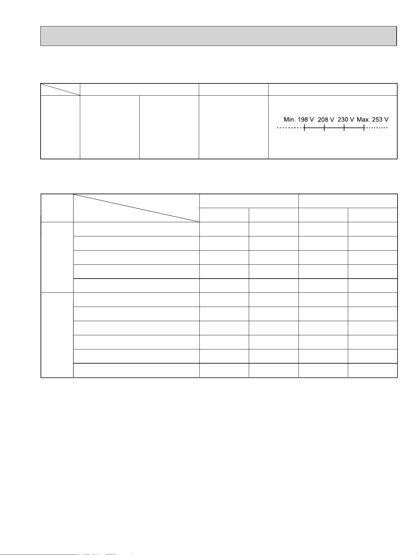
(2) OPERATION
8-1. OPERATING RANGE
(1) POWER SUPPLY
Function
Cooling
Heating
"A" Cooling steady state
at rated compressor speed
"B-2" Cooling steady state
at rated compressor speed
"B-1" Cooling steady state
at minimum compressor speed
Low ambient cooling steady state
at minimum compressor speed
Intermediate cooling steady state
at intermediate compressor speed
Standard rating-heating
at rated compressor speed
Low temperature heating
at rated compressor speed
Max. temperature heating
at minimum compressor speed
High temperature heating
at minimum compressor speed
Frost accumulation
at rated compressor speed
Frost accumulation
at intermediate compressor speed
DB (°F)
80
80
80
80
80
70
70
70
70
70
70
WB (°F)
67
67
67
67
67
60
60
60
60
60
60
Indoor
DB (°F)
95
82
82
67
87
47
17
62
47
35
35
WB (°F)
(75)
(65)
(65)
(53.5)
(69)
43
15
56.5
43
33
33
Outdoor
Condition
Intake air
temperature
Model Rating Guaranteed Voltage
Outdoor unit
MXZ-3C24NA
MXZ-3C30NA
MXZ-4C36NA
MXZ-5C42NA
MXZ-3C24NA2
MXZ-3C30NA2
MXZ-4C36NA2
MXZ-5C42NA2
MXZ-2C20NAHZ
MXZ-3C24NAHZ
MXZ-3C30NAHZ
MXZ-2C20NAHZ2
MXZ-3C24NAHZ2
MXZ-3C30NAHZ2
208/230 V 60 Hz 1ø
OBH702C
46
MXZ-3C24NA MXZ-3C30NA MXZ-4C36NA MXZ-5C42NA
MXZ-2C20NAHZ MXZ-3C24NAHZ MXZ-3C30NAHZ
MXZ-3C24NA2 MXZ-3C30NA2 MXZ-4C36NA2 MXZ-5C42NA2
MXZ-2C20NAHZ2 MXZ-3C24NAHZ2 MXZ-3C30NAHZ2
The standard specifications apply only to the operation of the air conditioner under normal conditions.
Since operating conditions vary according to the areas where these units are installed, the following information has been pro-
vided to clarify the operating characteristics of the air conditioner under the conditions indicated by the performance curve.
(1) GUARANTEED VOLTAGE
198 ~ 253 V 60 Hz
(2) AIR FLOW
Air flow should be set at MAX.
(3) MAIN READINGS
(1) Indoor intake air wet-bulb temperature : °FWB
(2) Indoor outlet air wet-bulb temperature : °FWB
(3) Outdoor intake air dry-bulb temperature : °FDB
(4) Total input: W
(5) Indoor intake air dry-bulb temperature : °FDB
(6) Outdoor intake air wet-bulb temperature : °FWB
(7) Total input : W
Indoor air wet and dry bulb temperature difference on the left side of the following chart shows the difference between the
indoor intake air wet and dry bulb temperature and the indoor outlet air wet and dry bulb temperature for your reference at
service.
}
}
Cooling
Heating
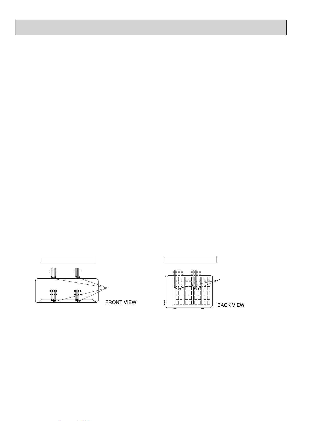
How to measure the indoor air wet and dry bulb temperature difference
1. Attach at least 2 sets of wet and dry bulb thermometers to the indoor air intake as shown in the figure, and at least 2 sets
of wet and dry bulb thermometers to the indoor air outlet. The thermometers must be attached to the position where air
speed is high.
2. Attach at least 2 sets of wet and dry bulb thermometers to the outdoor air intake.
Cover the thermometers to prevent direct rays of the sun.
3. Check that the air filter is cleaned.
4. Open windows and doors of room.
5. Press the EMERGENCY OPERATION switch once (twice) to start the EMERGENCY COOL (HEAT) MODE.
6. Compressor starts running at 33 Hz (COOL) or 45 Hz (HEAT). The frequency at each operation mode is fixed.
7. When system stabilizes after more than 15 minutes, measure temperature and take an average temperature.
8. 10 minutes later, measure temperature again and check that the temperature does not change.
INDOOR UNIT OUTDOOR UNIT
Wet and dry bulb
thermometers
Wet and dry bulb
thermometers
OBH702C
47
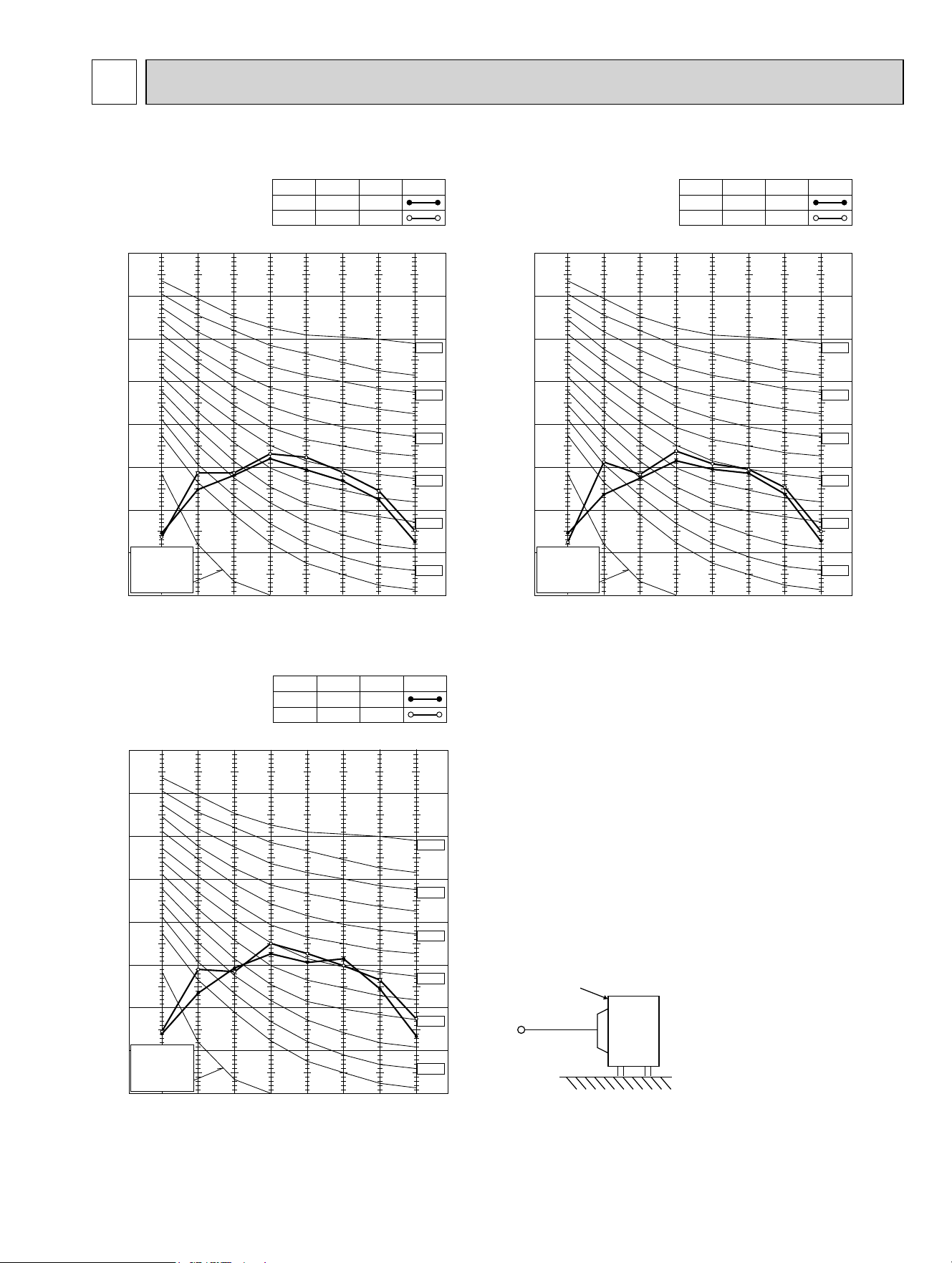
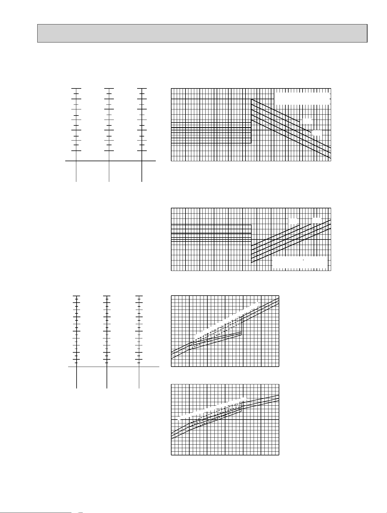
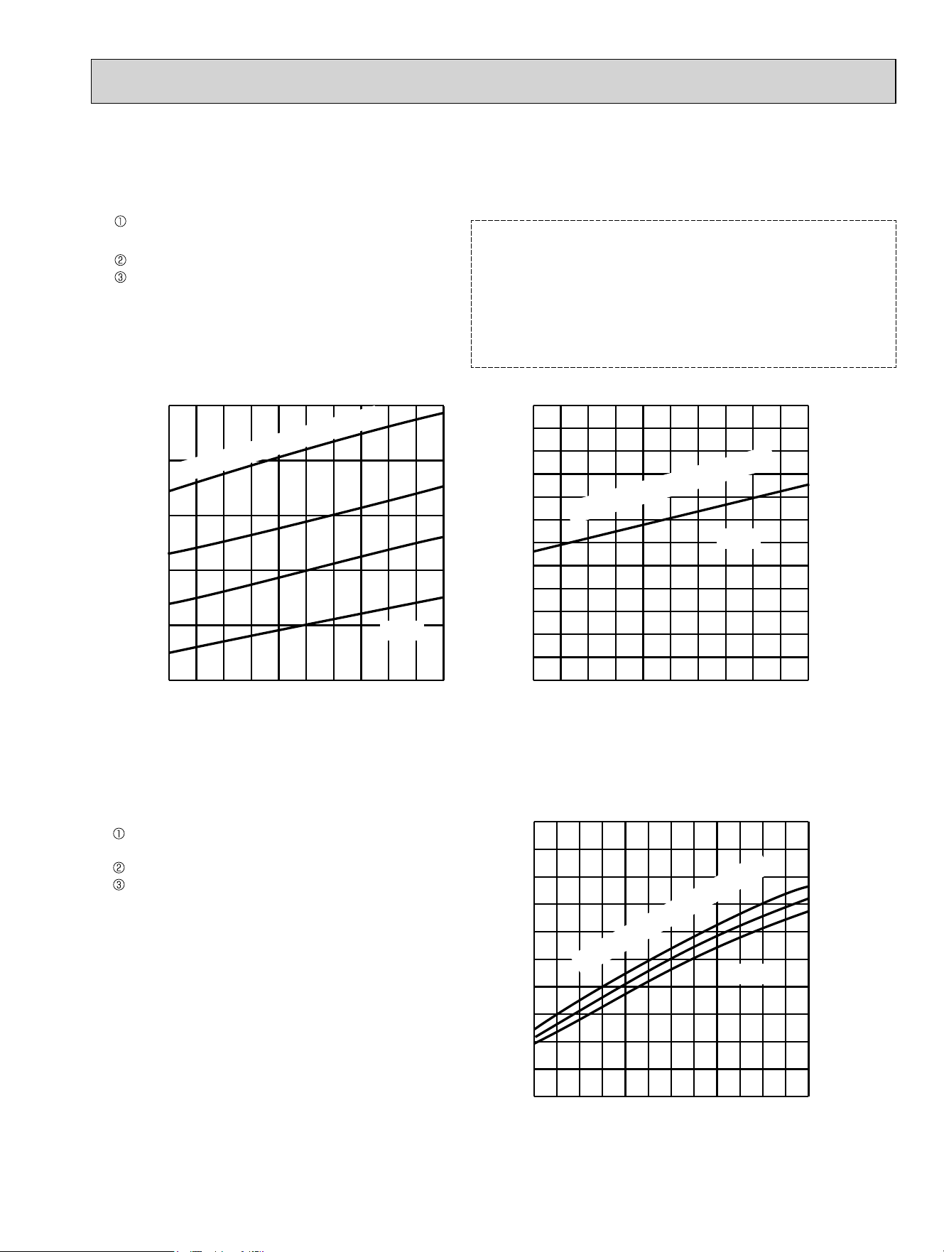
NOTE: The above broken lines are for the heating operation without any frost and defrost operation.
MXZ-3C24NA MXZ-3C30NA MXZ-4C36NA
MXZ-3C24NA2 MXZ-3C30NA2 MXZ-4C36NA2
06 class
(19Hz)
24 class
(54Hz)
18 class
(42Hz)
15 class
(35Hz)
12 class
(31Hz)
Indoor unit class
(Inverter output
frequency)
Indoor air Wet-bulb temperature
difference (degree)
09 class
(24Hz)
11.3
10.5
9.6
8.8
8.0
7.2
6.5
7.9
7.3
6.8
6.2
5.7
5.1
4.6
13.8
12.7
11.7
10.7
9.7
8.7
7.8
13.5
12.4
11.4
10.5
9.5
8.5
7.6
15.6
14.4
13.2
12.1
10.9
9.8
8.7
17.1
15.8
14.5
13.2
12.0
10.7
9.5
*
Cooling capacity (
at Rated frequency)
0.9
1.0
1.1
1.2
1.3
1.4
1.5
14 23 32 41 50 59 68 77 86 95 104 113
Outdoor intake air Dry-bulb temperature(°F)
Capacity correction factors
79
75
68
64
72
Indoor intake air Wet-bulb
temperature(°F)
0.8
0.9
1.0
1.1
1.2
1.3
14 23 32 41 50 59 68 77 86 95 104 113
Outdoor intake air Dry-bulb temperature (°F)
79
75
72
68
64
Input correction factors
Indoor intake air Wet-bulb
temperature( F)
Total input (Cooling :
at Rated frequency
)
09 class
(29Hz)
12 class
(36Hz)
15 class
(43Hz)
Indoor unit class
(Inverter output
frequency)
Indoor air Dry-bulb temperature
difference (degree)
39.8
36.7
33.7
30.2
27.2
24.1
21.4
18.0
15.1
11.9
53.3
49.1
45.2
40.5
36.5
32.4
29.0
24.1
20.5
16.0
34.0
31.3
28.8
25.7
23.2
20.7
18.0
15.3
13.0
10.3
24.3
22.5
20.5
18.5
16.6
14.8
13.0
11.0
9.2
7.4
44.8
41.4
38.0
34.0
30.6
27.2
24.1
20.2
17.1
13.5
49.1
45.4
41.6
37.4
33.7
29.9
26.5
22.1
18.7
14.8
06 class
(23Hz)
24 class
(62Hz)
*
18 class
(50Hz)
Outdoor intake air Wet-bulb temperature (°F)
5 142332415059
0.4
0.5
0.6
0.7
0.8
0.9
1.0
1.1
1.2
1.3
Heating capacity
(
at Rated frequency)
Capacity correction factor
59
68
779
Outdoor intake air Wet-bulb temperature (°F)
5 142332415059
0.4
0.5
0.6
0.7
0.8
0.9
1.0
1.1
1.2
1.3
Total input (Heating
:
at Rated frequency
)
Input correction factor
59
68
79
Indoor intake air Dry-bulb temperature (°F)
Indoor intake air Dry-bulb temperature (°F)
8-2. CAPACITY AND THE INPUT CURVES
* MXZ-3C30/4C36NA
MXZ-3C30/4C36NA2
OBH702C
48
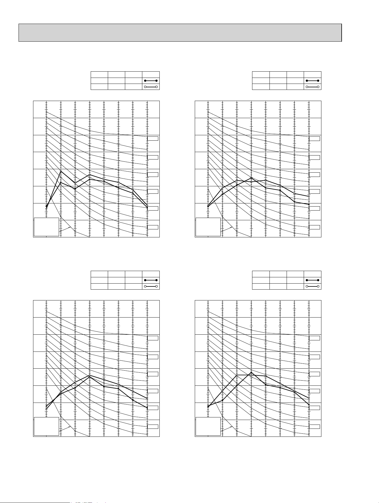
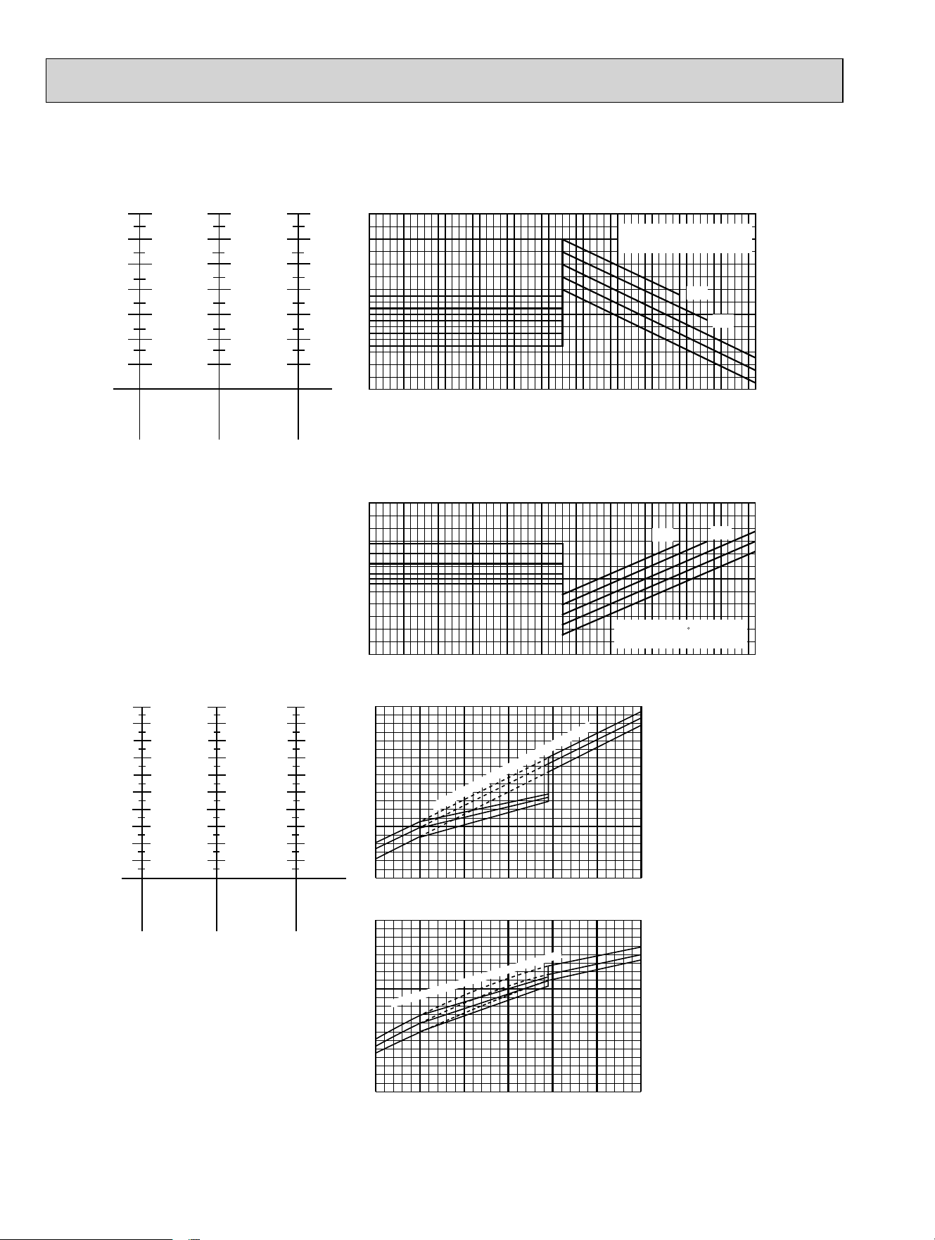
NOTE: The above broken lines are for the heating operation without any frost and defrost operation.
MXZ-5C42NA MXZ-2C20NAHZ MXZ-3C24NAHZ MXZ-3C30NAHZ
MXZ-5C42NA2 MXZ-2C20NAHZ2 MXZ-3C24NAHZ2 MXZ-3C30NAHZ2
06 class
(18Hz)
24 class
(42Hz)
18 class
(32Hz)
15 class
(26Hz)
12 class
(24Hz)
Indoor unit class
(Inverter output
frequency)
Indoor air Wet-bulb temperature
difference (degree)
09 class
(20Hz)
11.3
10.5
9.6
8.8
8.0
7.2
6.5
7.9
7.3
6.8
6.2
5.7
5.1
4.6
13.8
12.7
11.7
10.7
9.7
8.7
7.8
13.5
12.4
11.4
10.5
9.5
8.5
7.6
15.6
14.4
13.2
12.1
10.9
9.8
8.7
17.1
15.8
14.5
13.2
12.0
10.7
9.5
*1
*2
Cooling capacity (
at Rated frequency)
0.9
1.0
1.1
1.2
1.3
1.4
1.5
14 23 32 41 50 59 68 77 86 95 104 113
Outdoor intake air Dry-bulb temperature(°F)
Capacity correction factors
79
75
68
64
72
Indoor intake air Wet-bulb
temperature(°F)
0.8
0.9
1.0
1.1
1.2
1.3
14 23 32 41 50 59 68 77 86 95 104 113
Outdoor intake air Dry-bulb temperature (°F)
79
75
72
68
64
Input correction factors
Indoor intake air Wet-bulb
temperature( F)
Total input (Cooling :
at Rated frequency
)
09 class
(20Hz)
12 class
(28Hz)
15 class
(33Hz)
Indoor unit class
(Inverter output
frequency)
Indoor air Dry-bulb temperature
difference (degree)
39.8
36.7
33.7
30.2
27.2
24.1
21.4
18.0
15.1
11.9
53.3
49.1
45.2
40.5
36.5
32.4
29.0
24.1
20.5
16.0
34.0
31.3
28.8
25.7
23.2
20.7
18.0
15.3
13.0
10.3
24.3
22.5
20.5
18.5
16.6
14.8
13.0
11.0
9.2
7.4
44.8
41.4
38.0
34.0
30.6
27.2
24.1
20.2
17.1
13.5
49.1
45.4
41.6
37.4
33.7
29.9
26.5
22.1
18.7
14.8
06 class
(18Hz)
24 class
(44Hz)
18 class
(37Hz)
*1
*2
*1
*2
MXZ-5C42NA, MXZ-3C24/30NAHZ
MXZ-5C42NA2, MXZ-3C24/30NAHZ2
MXZ-5C42NA,MXZ-3C30NAHZ
MXZ-5C42NA2, MXZ-3C30NAHZ2
Outdoor intake air Wet-bulb temperature (°F)
5 142332415059
0.4
0.5
0.6
0.7
0.8
0.9
1.0
1.1
1.2
1.3
Heating capacity (
at Rated frequency)
Capacity correction factor
59
68
779
Outdoor intake air Wet-bulb temperature (°F)
5 142332415059
0.4
0.5
0.6
0.7
0.8
0.9
1.0
1.1
1.2
1.3
Total input (Heating :
at Rated frequency
)
Input correction factor
59
68
79
Indoor intake air Dry-bulb temperature (°F)
Indoor intake air Dry-bulb temperature (°F)
OBH702C
49
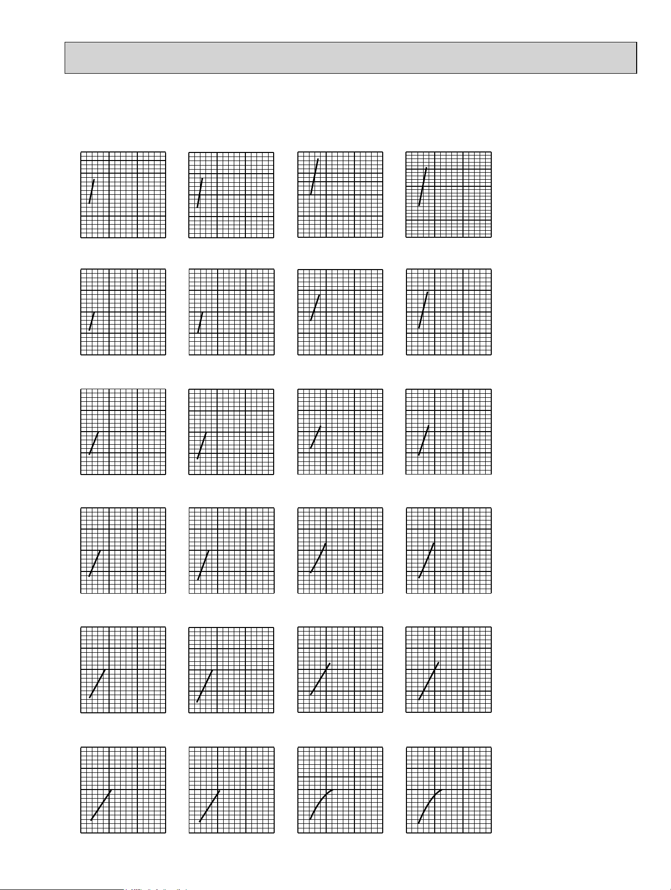
8-3. CAPACITY AND INPUT CORRECTION BY MEANS OF INVERTER OUTPUT FREQUENCY
(OUTDOOR UNIT: MXZ-3C24NA MXZ-3C30NA MXZ-4C36NA
MXZ-3C24NA2 MXZ-3C30NA2 MXZ-4C36NA2)
0 50 100 150
0.5
1.0
1.5
2.0
<COOL>Total input
Frequency
Hz
<HEAT>Capacity
Frequency
Hz
0 50 100 150
0.5
1.0
1.5
2.0
0 50 100 150
0.5
1.0
1.5
2.0
2.5
<HEAT>Total input
Frequency
Hz
<COOL>Capacity
Frequency
Hz
0 50 100 150
0.5
1.0
1.5
2.0
<HEAT>Capacity <HEAT>Total input
Frequency
Hz
Frequency
Hz
0 50 100 150
0.5
1.0
1.5
2.0
0 50 100 150
0.5
1.0
1.5
2.0
<COOL>Capacity
Frequency
Hz
0 50 100 150
0.5
1.0
1.5
2.0
0 50 100 150
0.5
1.0
1.5
2.0
<COOL>Total input
Frequency
Hz
0 50 100 150
0.5
1.0
1.5
2.0
<COOL>Total input
Frequency
Hz
<HEAT>Capacity
Frequency
Hz
0 50 100 150
0.5
1.0
1.5
2.0
0 50 100 150
0.5
1.0
1.5
2.0
<HEAT>Total input
Frequency
Hz
<COOL>Capacity
Frequency
Hz
0 50 100 150
0.5
1.0
1.5
2.0
<HEAT>Capacity <HEAT>Total input
Frequency
Hz
Frequency
Hz
0 50 100 150
0.5
1.0
1.5
2.0
050100150
0.5
1.0
1.5
2.0
<COOL>Capacity
Frequency
Hz
0 50 100 150
0.5
1.0
1.5
2.0
0 50 100 150
0.5
1.0
1.5
2.0
<COOL>Total input
Frequency
Hz
2. 09-class unit in single operation
1. 06-class unit in single operation
3. 12-class unit in single operation
4. 15-class unit in single operation
5. 18-class unit in single operation
6. 24-class unit in single operation (MXZ-3C30/4C36NA, MXZ-3C30/4C36NA2 only)
OBH702C
50
(OUTDOOR UNIT: MXZ-5C42NA MXZ-2C20NAHZ MXZ-3C24NAHZ MXZ-3C30NAHZ
MXZ-5C42NA2 MXZ-2C20NAHZ2 MXZ-3C24NAHZ2 MXZ-3C30NAHZ2)
0 50 100 150
0.5
1.0
1.5
2.0
<COOL>Total input
Frequency
Hz
<HEAT>Capacity
Frequency
Hz
0 50 100 150
0.5
1.0
1.5
2.0
0 50 100 150
0.5
1.0
1.5
2.0
<HEAT>Total input
Frequency
Hz
<COOL>Capacity
Frequency
Hz
0 50 100 150
0.5
1.0
1.5
2.0
<HEAT>Capacity <HEAT>Total input
Frequency
Hz
Frequency
Hz
0 50 100 150
0.5
1.0
1.5
2.0
0 50 100 150
0.5
1.0
1.5
2.0
<COOL>Capacity
Frequency
Hz
0 50 100 150
0.5
1.0
1.5
2.0
0 50 100 150
0.5
1.0
1.5
2.0
<COOL>Total input
Frequency
Hz
050100150
0.5
1.0
1.5
2.0
<COOL>Total input
Frequency
Hz
<HEAT>Capacity
Frequency
Hz
0 50 100 150
0.5
1.0
1.5
2.0
0 50 100 150
0.5
1.0
1.5
2.0
<HEAT>Total input
Frequency
Hz
<COOL>Capacity
Frequency
Hz
0 50 100 150
0.5
1.0
1.5
2.0
<HEAT>Capacity <HEAT>Total input
Frequency
Hz
Frequency
Hz
0 50 100 150
0.5
1.0
1.5
2.0
0 50 100 150
0.5
1.0
1.5
2.0
<COOL>Capacity
Frequency
Hz
0 50 100 150
0.5
1.0
1.5
2.0
0 50 100 150
0.5
1.0
1.5
2.0
<COOL>Total input
Frequency
Hz
0 50 100 150
0.5
1.0
1.5
2.0
<COOL>Total input
Frequency
Hz
<HEAT>Capacity
Frequency
Hz
0 50 100 150
0.5
1.0
1.5
2.0
0 50 100 150
0.5
1.0
1.5
2.0
<HEAT>Total input
Frequency
Hz
<COOL>Capacity
Frequency
Hz
0 50 100 150
0.5
1.0
1.5
2.0
<HEAT>Capacity <HEAT>Total input
Frequency
Hz
Frequency
Hz
0 50 100 150
0.5
1.0
1.5
2.0
0 50 100 150
0.5
1.0
1.5
2.0
<COOL>Capacity
Frequency
Hz
0 50 100 150
0.5
1.0
1.5
2.0
0 50 100 150
0.5
1.0
1.5
2.0
<COOL>Total input
Frequency
Hz
2. 09-class unit in single operation
1. 06-class unit in single operation
3. 12-class unit in single operation
4. 15-class unit in single operation
5. 18-class unit in single operation (MXZ-5C42NA, MXZ-5C42NA2, MXZ-3C24/30NAHZ, MXZ-3C24/30NAHZ2 only)
6. 24-class unit in single operation (MXZ-5C42NA, MXZ-5C42NA2, MXZ-3C30NAHZ, MXZ-3C30NAHZ2 only)
OBH702C
51
65 70 75 80 85 90 95 100 105 110 115
0.0
1.0
2.0
3.0
4.0
5.0
6.0
$PELHQWWHPSHUDWXUHÛ)
Û)
Û)
15 20 25 30 35 40 45 50 55 60 65 70 75
2.0
3.0
4.0
5.0
6.0
7.0
$PELHQWWHPSHUDWXUHÛ)
Outdoor low pressure
2XWGRRUXQLWFXUUHQW$
2XWGRRUXQLWFXUUHQW$
32 Hz
36,*
24 Hz
24 Hz
65
75
70
86
80
75
70
,QGRRU'U\EXOEWHPSHUDWXUHÛ)
,QGRRU'U\EXOEWHPSHUDWXUHÛ)
65 70 75 80 85 90 95 100 105 110 115
110
120
130
140
150
160
$PELHQWWHPSHUDWXUHÛ)
Û)
86
80
75
70
,QGRRU'U\EXOEWHPSHUDWXUHÛ)
1. 06-class unit in single operation (OUTDOOR UNIT: MXZ-3C24NA MXZ-3C30NA MXZ-4C36NA
MXZ-3C24NA2 MXZ-3C30NA2 MXZ-4C36NA2)
(1) COOL operation
8-4. OUTDOOR LOW PRESSURE AND OUTDOOR UNIT CURRENT
Data is based on the condition of indoor
humidity 50%
Air flow speed: High
Inverter output frequency: 24 Hz
(2) HEAT operation
<How to work fixed-frequency operation>
1. Set emergency switch to COOL or HEAT. The switch is located
on indoor unit.
2. Press emergency run ON/OFF button.
3. Compressor starts running at 24 Hz (COOL) or 32 Hz (HEAT).
4. Indoor fan runs at High speed and continues for 30 minutes.
5. To cancel this operation, press emergency run ON/OFF button
or any button on remote controller.
Data is based on the condition of outdoor
humidity 75%.
Set air flow to High speed.
Inverter output frequency is 32 Hz.
OBH702C
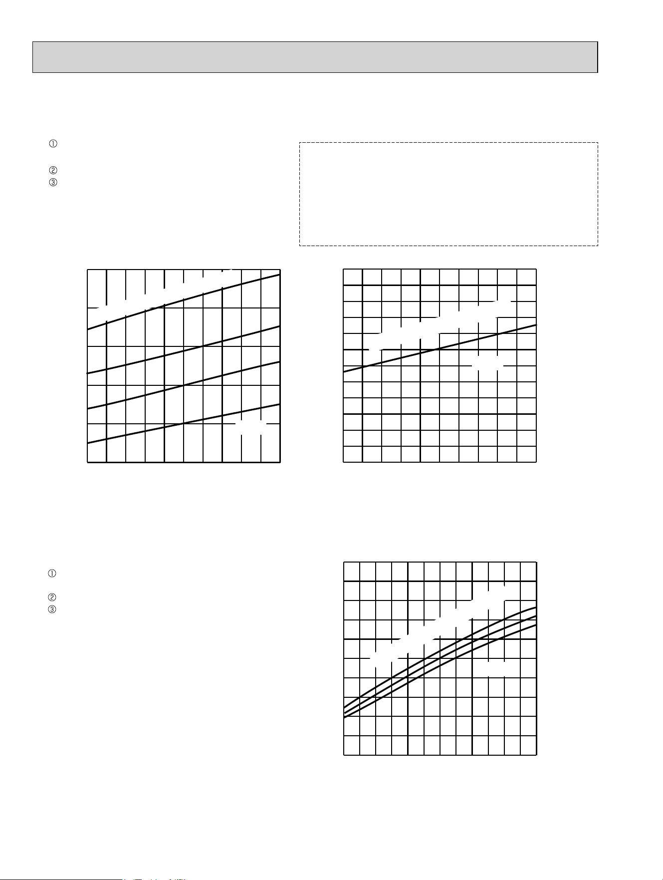
52
65 70 75 80 85 90 95 100 105 110 115
0.0
1.0
2.0
3.0
4.0
5.0
6.0
$PELHQWWHPSHUDWXUHÛ)
Û)
Û)
15 20 25 30 35 40 45 50 55 60 65 70 75
2.0
3.0
4.0
5.0
6.0
7.0
$PELHQWWHPSHUDWXUHÛ)
Outdoor low pressure
2XWGRRUXQLWFXUUHQW$
2XWGRRUXQLWFXUUHQW$
32 Hz
36,*
24 Hz
24 Hz
65
75
70
86
80
75
70
,QGRRU'U\EXOEWHPSHUDWXUHÛ)
,QGRRU'U\EXOEWHPSHUDWXUHÛ)
65 70 75 80 85 90 95 100 105 110 115
110
120
130
140
150
160
$PELHQWWHPSHUDWXUHÛ)
Û)
86
80
75
70
,QGRRU'U\EXOEWHPSHUDWXUHÛ)
2. 09-class unit in single operation (OUTDOOR UNIT: MXZ-3C24NA MXZ-3C30NA MXZ-4C36NA
MXZ-3C24NA2 MXZ-3C30NA2 MXZ-4C36NA2)
(1) COOL operation
Data is based on the condition of indoor
humidity 50%
Air flow speed: High
Inverter output frequency: 24 Hz
(2) HEAT operation
Data is based on the condition of outdoor
humidity 75%.
Set air flow to High speed.
Inverter output frequency is 32 Hz.
<How to work fixed-frequency operation>
1. Set emergency switch to COOL or HEAT. The switch is located
on indoor unit.
2. Press emergency run ON/OFF button.
3. Compressor starts running at 24 Hz (COOL) or 32 Hz (HEAT).
4. Indoor fan runs at High speed and continues for 30 minutes.
5. To cancel this operation, press emergency run ON/OFF button
or any button on remote controller.
OBH702C
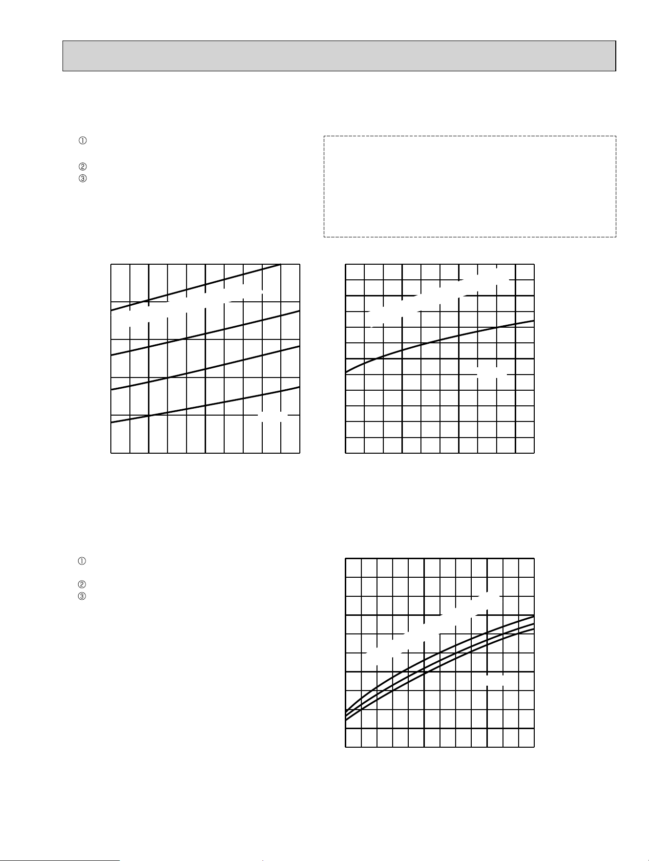
53
65 70 75 80 85 90 95 100 105 110 115
110
120
130
140
150
160
Ambient temperature (˚F)
(˚F)
86
80
75
70
86
80
75
70
15 20 25 30 35 40 45 50 55 60 65 70 75
2.0
3.0
4.0
5.0
6.0
7.0
Ambient temperature (˚F)
65 70 75 80 85 90 95 100 105 110 115
0.0
1.0
2.0
3.0
4.0
5.0
6.0
Ambient temperature (˚F)
(˚F)
(˚F)
(PSIG)
Outdoor low pressure
Outdoor unit current (A)
Outdoor unit current (A)
32 Hz
24 Hz
24 Hz
65
70
75
Indoor Dry-bulb temperature (˚F)
Indoor Dry-bulb temperature (˚F)
Indoor Dry-bulb temperature (˚F)
3. 12-class unit in single operation (OUTDOOR UNIT: MXZ-3C24NA MXZ-3C30NA MXZ-4C36NA
MXZ-3C24NA2 MXZ-3C30NA2 MXZ-4C36NA2)
(1) COOL operation
Air flow speed: High
Inverter output frequency: 24 Hz
(2) HEAT operation
Data is based on the condition of indoor
humidity 50%
Data is based on the condition of outdoor
humidity 75%.
Set air flow to High speed.
Inverter output frequency is 32 Hz.
<How to work fixed-frequency operation>
1. Set emergency switch to COOL or HEAT. The switch is located
on indoor unit.
2. Press emergency run ON/OFF button.
3. Compressor starts running at 24 Hz (COOL) or 32 Hz (HEAT).
4. Indoor fan runs at High speed and continues for 30 minutes.
5. To cancel this operation, press emergency run ON/OFF button
or any button on remote controller.
OBH702C
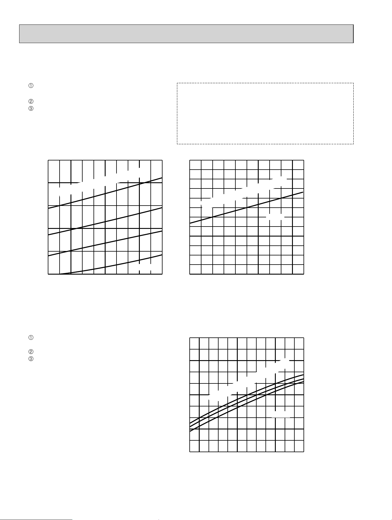
54
4. 15-class unit in single operation (OUTDOOR UNIT: MXZ-3C24NA MXZ-3C30NA MXZ-4C36NA
MXZ-3C24NA2 MXZ-3C30NA2 MXZ-4C36NA2)
(1) COOL operation
65 70 75 80 85 90 95 100 105 110 115
120
130
140
150
160
170
Ambient temperature (˚F)
(˚F)
86
80
75
70
86
80
75
70
15 20 25 30 35 40 45 50 55 60 65 70 75
2.0
3.0
4.0
5.0
6.0
7.0
Ambient temperature (˚F)
65 70 75 80 85 90 95 100 105 110 115
0.0
1.0
2.0
3.0
4.0
5.0
6.0
Ambient temperature (˚F)
(˚F)
(˚F)
(PSIG)
Outdoor low pressure
Outdoor unit current (A)
Outdoor unit current (A)
32 Hz
24 Hz
24 Hz
65
70
75
Indoor Dry-bulb temperature (˚F)
Indoor Dry-bulb temperature (˚F)
Indoor Dry-bulb temperature (˚F)
(2) HEAT operation
Data is based on the condition of outdoor
humidity 75%
Set air flow to High speed.
Inverter output frequency is 32 Hz.
Air flow speed: High
Inverter output frequency: 24 Hz
Data is based on the condition of indoor
humidity 50%
<How to work fixed-frequency operation>
1. Set emergency switch to COOL or HEAT. The switch is located
on indoor unit.
2. Press emergency run ON/OFF button.
3. Compressor starts running at 24 Hz (COOL) or 32 Hz (HEAT).
4. Indoor fan runs at High speed and continues for 30 minutes.
5. To cancel this operation, press emergency run ON/OFF button
or any button on remote controller.
OBH702C
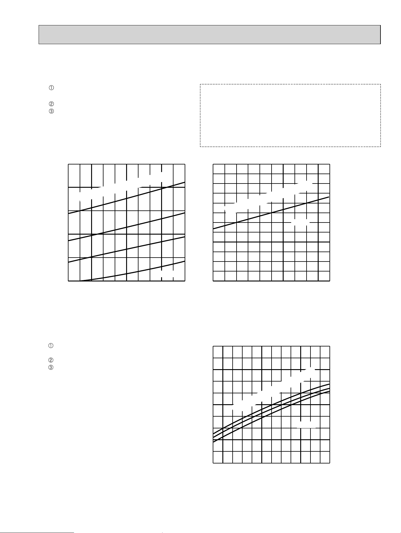
55
5. 18-class unit in single operation (OUTDOOR UNIT: MXZ-3C24NA MXZ-3C30NA MXZ-4C36NA
MXZ-3C24NA2 MXZ-3C30NA2 MXZ-4C36NA2)
(1) COOL operation
(2) HEAT operation
65 70 75 80 85 90 95 100 105 110 115
120
130
140
150
160
170
Ambient temperature (˚F)
(˚F)
86
80
75
70
86
80
75
70
15 20 25 30 35 40 45 50 55 60 65 70 75
2.0
3.0
4.0
5.0
6.0
7.0
Ambient temperature (˚F)
65 70 75 80 85 90 95 100 105 110 115
0.0
1.0
2.0
3.0
4.0
5.0
6.0
Ambient temperature (˚F)
(˚F)
(˚F)
(PSIG)
Outdoor low pressure
Outdoor unit current (A)
Outdoor unit current (A)
32 Hz
24 Hz
24 Hz
65
70
75
Indoor Dry-bulb temperature (˚F)
Indoor Dry-bulb temperature (˚F)
Indoor Dry-bulb temperature (˚F)
Data is based on the condition of outdoor
humidity 75%.
Set air flow to High speed.
Inverter output frequency is 32 Hz.
Air flow speed: High
Inverter output frequency: 24 Hz
Data is based on the condition of indoor
humidity 50%
<How to work fixed-frequency operation>
1. Set emergency switch to COOL or HEAT. The switch is located
on indoor unit.
2. Press emergency run ON/OFF button.
3. Compressor starts running at 24 Hz (COOL) or 32 Hz (HEAT).
4. Indoor fan runs at High speed and continues for 30 minutes.
5. To cancel this operation, press emergency run ON/OFF button
or any button on remote controller.
OBH702C
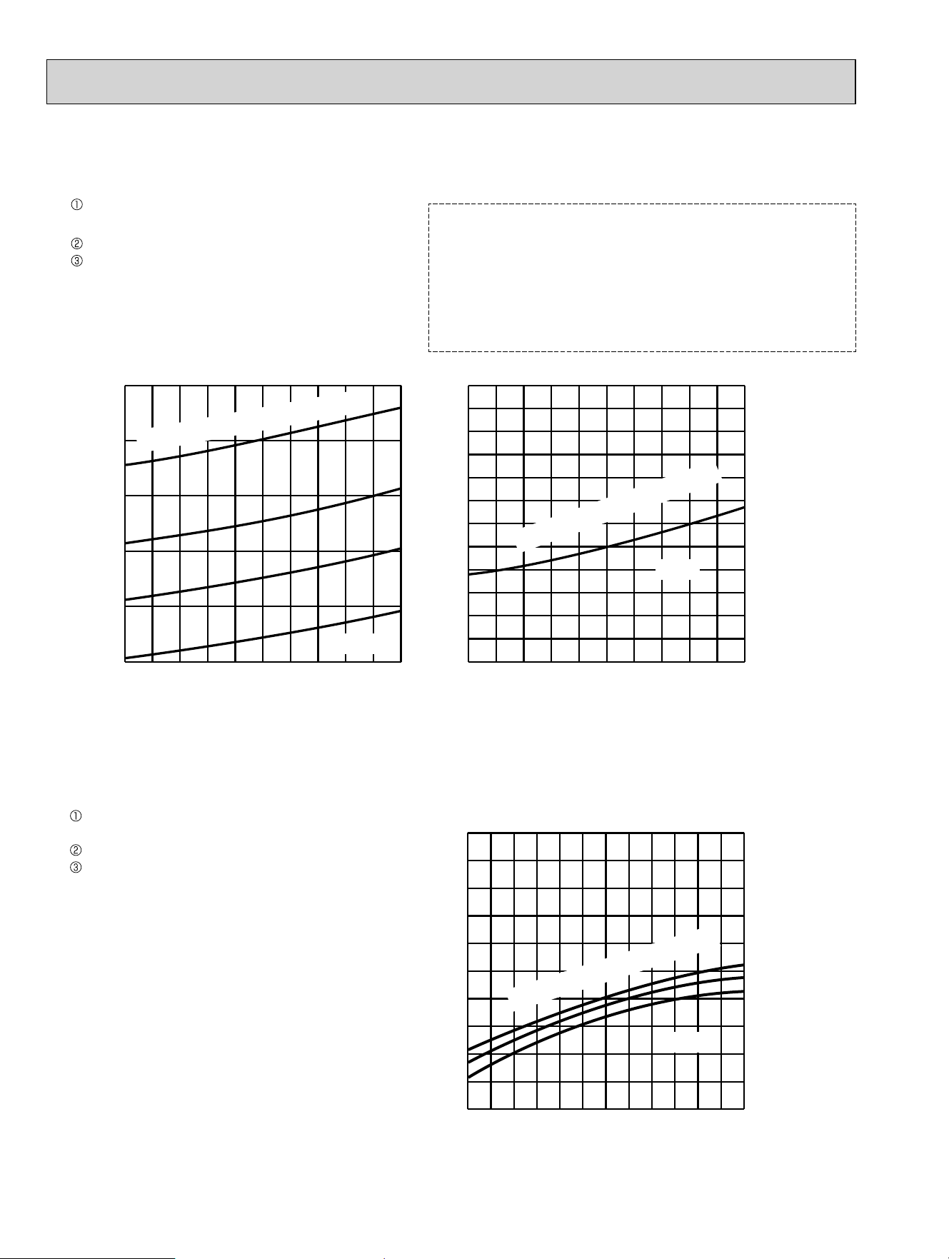
56
6. 24-class unit in single operation (OUTDOOR UNIT: MXZ-3C30NA MXZ-4C36NA
MXZ-3C30NA2 MXZ-4C36NA2)
(1) COOL operation
65 70 75 80 85 90 95 100 105 110 115
130
140
150
160
170
180
Ambient temperature (˚F)
(˚F)
15 20 25 30 35 40 45 50 55 60 65 70 75
2.0
3.0
4.0
5.0
6.0
7.0
Ambient temperature (˚F)
65 70 75 80 85 90 95 100 105 110 115
1.0
2.0
3.0
4.0
5.0
6.0
7.0
Ambient temperature (˚F)
(˚F)
(˚F)
(PSIG)
Outdoor low pressure
Outdoor unit current (A)
Outdoor unit current (A)
32 Hz
24 Hz
24 Hz
86
80
75
70
75
70
65
Indoor Dry-bulb temperature (˚F)
Indoor Dry-bulb temperature (˚F)
Indoor Dry-bulb temperature (˚F)
86
80
75
70
(2) HEAT operation
Data is based on the condition of outdoor
humidity 75%
Set air flow to High speed.
Inverter output frequency is 32 Hz.
Air flow speed: High
Inverter output frequency: 24 Hz
Data is based on the condition of indoor
humidity 50%
<How to work fixed-frequency operation>
1. Set emergency switch to COOL or HEAT. The switch is located
on indoor unit.
2. Press emergency run ON/OFF button.
3. Compressor starts running at 24 Hz (COOL) or 32 Hz (HEAT).
4. Indoor fan runs at High speed and continues for 30 minutes.
5. To cancel this operation, press emergency run ON/OFF button
or any button on remote controller.
OBH702C

57
7. 06-class unit in single operation
(OUTDOOR UNIT: MXZ-5C42NA MXZ-2C20NAHZ MXZ-3C24NAHZ MXZ-3C30NAHZ
MXZ-5C42NA2 MXZ-2C20NAHZ2 MXZ-3C24NAHZ2 MXZ-3C30NAHZ2)
(1) COOL operation
Data is based on the condition of indoor
humidity 50%
Air flow speed: High
Inverter output frequency: 18 Hz
(2) HEAT operation
<How to work fixed-frequency operation>
1. Set emergency switch to COOL or HEAT. The switch is located
on indoor unit.
2. Press emergency run ON/OFF button.
3. Compressor starts running at 18 Hz (COOL) or 20 Hz (HEAT).
4. Indoor fan runs at High speed and continues for 30 minutes.
5. To cancel this operation, press emergency run ON/OFF button
or any button on remote controller.
65 70 75 80 85 90 95 100 105 110 115
120
130
140
150
160
170
$PELHQWWHPSHUDWXUHÛ)
Û)
,QGRRU'U\EXOEWHPSHUDWXUHÛ)
65 70 75 80 85 90 95 100 105 110 115
0.0
1.0
2.0
3.0
4.0
5.0
6.0
$PELHQWWHPSHUDWXUHÛ)
Û)
Û)
15 20 25 30 35 40 45 50 55 60 65 70 75
2.0
3.0
4.0
5.0
6.0
7.0
$PELHQWWHPSHUDWXUHÛ)
Outdoor low pressure
2XWGRRUXQLWFXUUHQW$
2XWGRRUXQLWFXUUHQW$
20 Hz
36,*
18 Hz
18 Hz
,QGRRU'U\EXOEWHPSHUDWXUHÛ)
,QGRRU'U\EXOEWHPSHUDWXUHÛ)
86
80
75
70
86
80
75
70
65
75
70
Data is based on the condition of outdoor
humidity 75%.
Set air flow to High speed.
Inverter output frequency is 20 Hz.
OBH702C
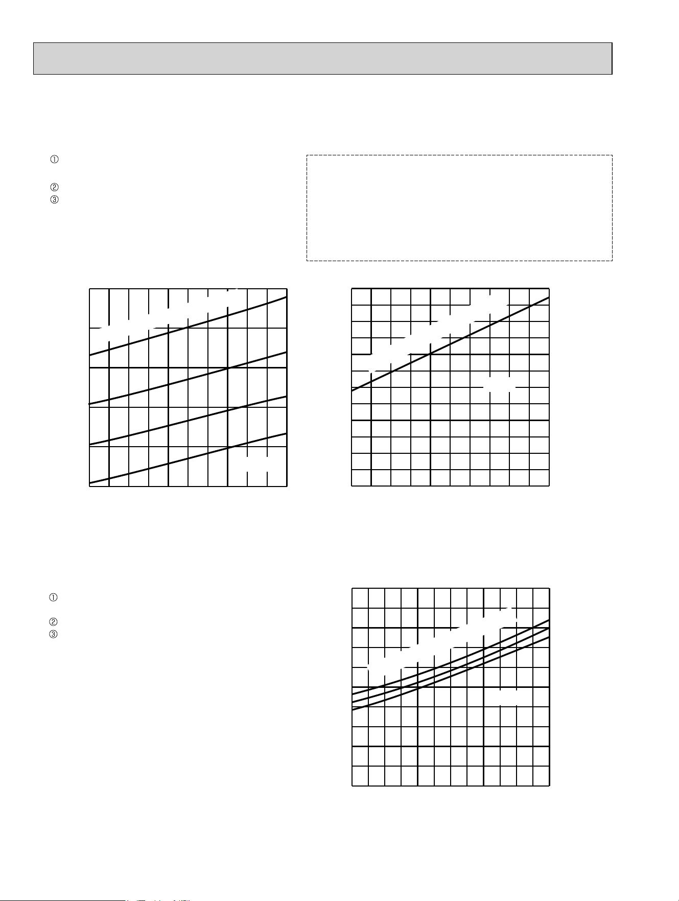
58
8. 09-class unit in single operation
(OUTDOOR UNIT: MXZ-5C42NA MXZ-2C20NAHZ MXZ-3C24NAHZ MXZ-3C30NAHZ
MXZ-5C42NA2 MXZ-2C20NAHZ2 MXZ-3C24NAHZ2 MXZ-3C30NAHZ2)
(1) COOL operation
Data is based on the condition of indoor
humidity 50%
Air flow speed: High
Inverter output frequency: 18 Hz
(2) HEAT operation
<How to work fixed-frequency operation>
1. Set emergency switch to COOL or HEAT. The switch is located
on indoor unit.
2. Press emergency run ON/OFF button.
3. Compressor starts running at 18 Hz (COOL) or 20 Hz (HEAT).
4. Indoor fan runs at High speed and continues for 30 minutes.
5. To cancel this operation, press emergency run ON/OFF button
or any button on remote controller.
65 70 75 80 85 90 95 100 105 110 115
120
130
140
150
160
170
$PELHQWWHPSHUDWXUHÛ)
Û)
,QGRRU'U\EXOEWHPSHUDWXUHÛ)
65 70 75 80 85 90 95 100 105 110 115
0.0
1.0
2.0
3.0
4.0
5.0
6.0
$PELHQWWHPSHUDWXUHÛ)
Û)
Û)
15 20 25 30 35 40 45 50 55 60 65 70 75
2.0
3.0
4.0
5.0
6.0
7.0
$PELHQWWHPSHUDWXUHÛ)
Outdoor low pressure
2XWGRRUXQLWFXUUHQW$
2XWGRRUXQLWFXUUHQW$
20 Hz
36,*
18 Hz
18 Hz
,QGRRU'U\EXOEWHPSHUDWXUHÛ)
,QGRRU'U\EXOEWHPSHUDWXUHÛ)
86
80
75
70
86
80
75
70
65
75
70
Data is based on the condition of outdoor
humidity 75%.
Set air flow to High speed.
Inverter output frequency is 20 Hz.
OBH702C
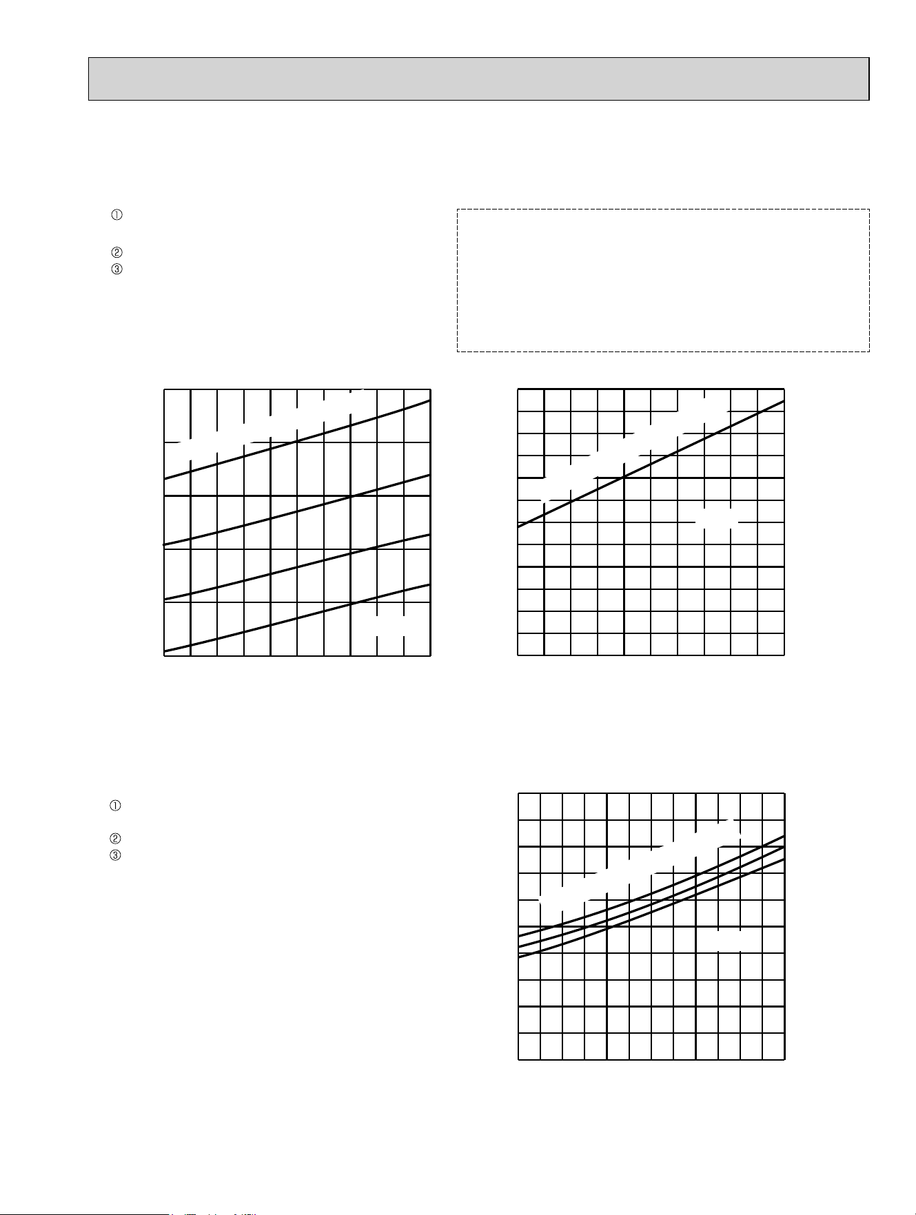
59
9. 12-class unit in single operation
(OUTDOOR UNIT: MXZ-5C42NA MXZ-2C20NAHZ MXZ-3C24NAHZ MXZ-3C30NAHZ
MXZ-5C42NA2 MXZ-2C20NAHZ2 MXZ-3C24NAHZ2 MXZ-3C30NAHZ2)
(1) COOL operation
Data is based on the condition of indoor
humidity 50%
Air flow speed: High
Inverter output frequency: 18 Hz
(2) HEAT operation
<How to work fixed-frequency operation>
1. Set emergency switch to COOL or HEAT. The switch is located
on indoor unit.
2. Press emergency run ON/OFF button.
3. Compressor starts running at 18 Hz (COOL) or 20 Hz (HEAT).
4. Indoor fan runs at High speed and continues for 30 minutes.
5. To cancel this operation, press emergency run ON/OFF button
or any button on remote controller.
65 70 75 80 85 90 95 100 105 110 115
120
130
140
150
160
170
$PELHQWWHPSHUDWXUHÛ)
Û)
,QGRRU'U\EXOEWHPSHUDWXUHÛ)
65 70 75 80 85 90 95 100 105 110 115
0.0
1.0
2.0
3.0
4.0
5.0
6.0
$PELHQWWHPSHUDWXUHÛ)
Û)
Û)
15 20 25 30 35 40 45 50 55 60 65 70 75
2.0
3.0
4.0
5.0
6.0
7.0
$PELHQWWHPSHUDWXUHÛ)
Outdoor low pressure
2XWGRRUXQLWFXUUHQW$
2XWGRRUXQLWFXUUHQW$
20 Hz
36,*
18 Hz
18 Hz
,QGRRU'U\EXOEWHPSHUDWXUHÛ)
,QGRRU'U\EXOEWHPSHUDWXUHÛ)
86
80
75
70
86
80
75
70
65
75
70
Data is based on the condition of outdoor
humidity 75%.
Set air flow to High speed.
Inverter output frequency is 20 Hz.
OBH702C
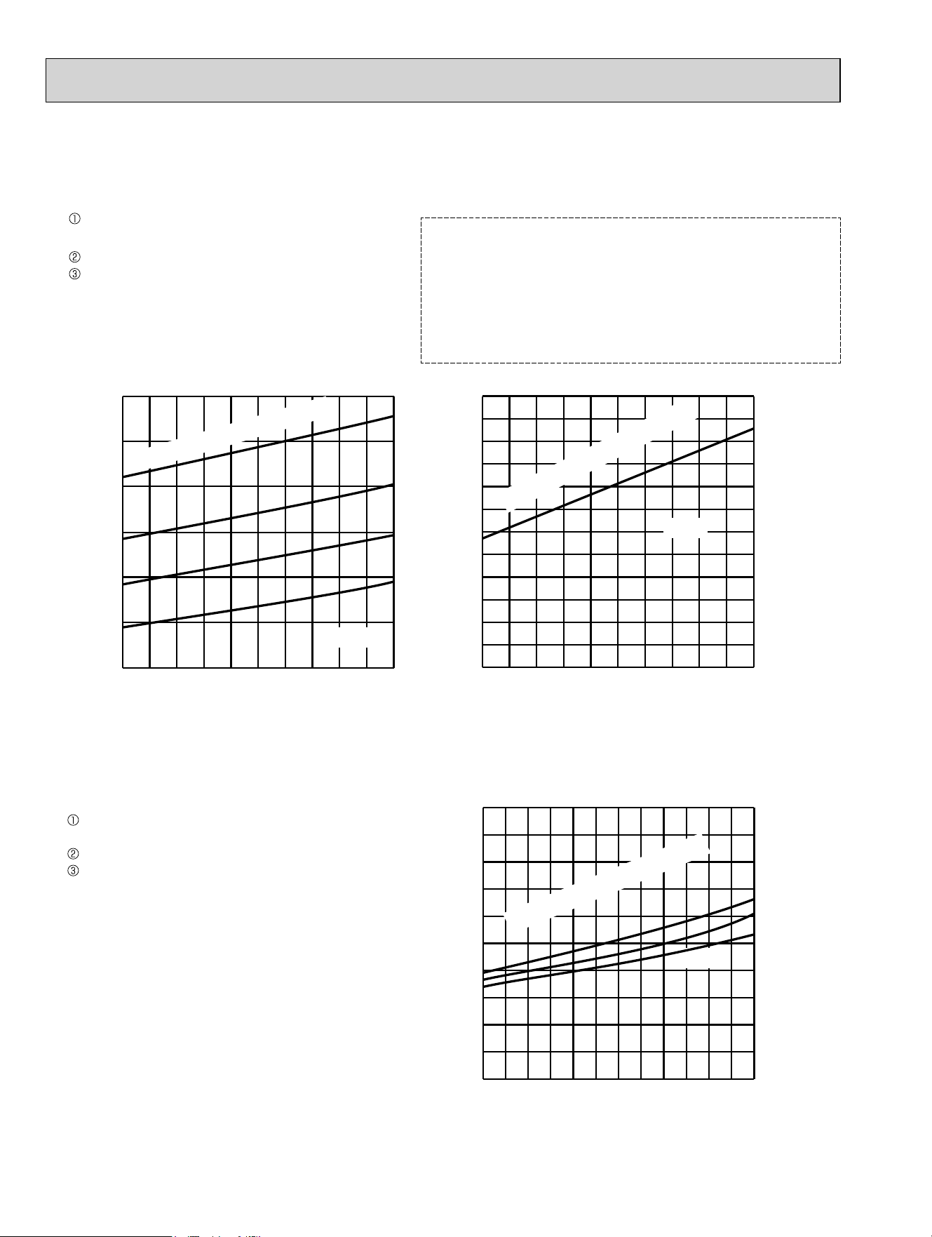
60
10. 15-class unit in single operation
(OUTDOOR UNIT: MXZ-5C42NA MXZ-2C20NAHZ MXZ-3C24NAHZ MXZ-3C30NAHZ
MXZ-5C42NA2 MXZ-2C20NAHZ2 MXZ-3C24NAHZ2 MXZ-3C30NAHZ2)
(1) COOL operation
Data is based on the condition of indoor
humidity 50%
Air flow speed: High
Inverter output frequency: 18 Hz
(2) HEAT operation
<How to work fixed-frequency operation>
1. Set emergency switch to COOL or HEAT. The switch is located
on indoor unit.
2. Press emergency run ON/OFF button.
3. Compressor starts running at 18 Hz (COOL) or 20 Hz (HEAT).
4. Indoor fan runs at High speed and continues for 30 minutes.
5. To cancel this operation, press emergency run ON/OFF button
or any button on remote controller.
65 70 75 80 85 90 95 100 105 110 115
120
130
140
150
170
180
160
$PELHQWWHPSHUDWXUHÛ)
Û)
,QGRRU'U\EXOEWHPSHUDWXUHÛ)
65 70 75 80 85 90 95 100 105 110 115
0.0
1.0
2.0
3.0
4.0
5.0
6.0
$PELHQWWHPSHUDWXUHÛ)
Û)
Û)
15 20 25 30 35 40 45 50 55 60 65 70 75
2.0
3.0
4.0
5.0
6.0
7.0
$PELHQWWHPSHUDWXUHÛ)
Outdoor low pressure
2XWGRRUXQLWFXUUHQW$
2XWGRRUXQLWFXUUHQW$
20 Hz
36,*
18 Hz
18 Hz
,QGRRU'U\EXOEWHPSHUDWXUHÛ)
,QGRRU'U\EXOEWHPSHUDWXUHÛ)
86
80
75
70
86
80
75
70
65
75
70
Data is based on the condition of outdoor
humidity 75%.
Set air flow to High speed.
Inverter output frequency is 20 Hz.
OBH702C
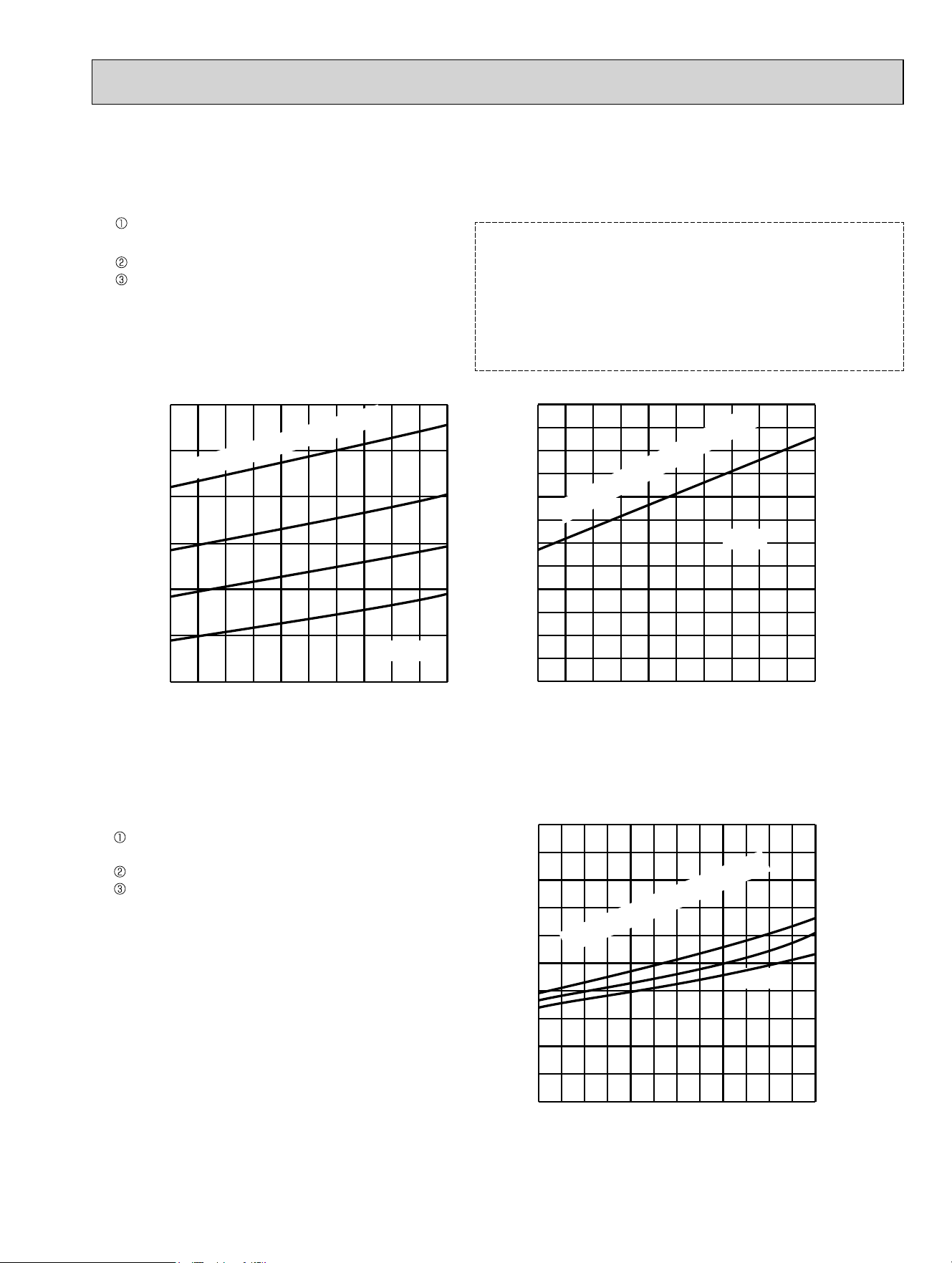
61
11. 18-class unit in single operation
(OUTDOOR UNIT: MXZ-5C42NA MXZ-3C24NAHZ MXZ-3C30NAHZ
MXZ-5C42NA2 MXZ-3C24NAHZ2 MXZ-3C30NAHZ2)
(1) COOL operation
Data is based on the condition of indoor
humidity 50%
Air flow speed: High
Inverter output frequency: 18 Hz
(2) HEAT operation
<How to work fixed-frequency operation>
1. Set emergency switch to COOL or HEAT. The switch is located
on indoor unit.
2. Press emergency run ON/OFF button.
3. Compressor starts running at 18 Hz (COOL) or 20 Hz (HEAT).
4. Indoor fan runs at High speed and continues for 30 minutes.
5. To cancel this operation, press emergency run ON/OFF button
or any button on remote controller.
65 70 75 80 85 90 95 100 105 110 115
120
130
140
150
170
180
160
$PELHQWWHPSHUDWXUHÛ)
Û)
,QGRRU'U\EXOEWHPSHUDWXUHÛ)
65 70 75 80 85 90 95 100 105 110 115
0.0
1.0
2.0
3.0
4.0
5.0
6.0
$PELHQWWHPSHUDWXUHÛ)
Û)
Û)
15 20 25 30 35 40 45 50 55 60 65 70 75
2.0
3.0
4.0
5.0
6.0
7.0
$PELHQWWHPSHUDWXUHÛ)
Outdoor low pressure
2XWGRRUXQLWFXUUHQW$
2XWGRRUXQLWFXUUHQW$
20 Hz
36,*
18 Hz
18 Hz
,QGRRU'U\EXOEWHPSHUDWXUHÛ)
,QGRRU'U\EXOEWHPSHUDWXUHÛ)
86
80
75
70
86
80
75
70
65
75
70
Data is based on the condition of outdoor
humidity 75%.
Set air flow to High speed.
Inverter output frequency is 20 Hz.
OBH702C
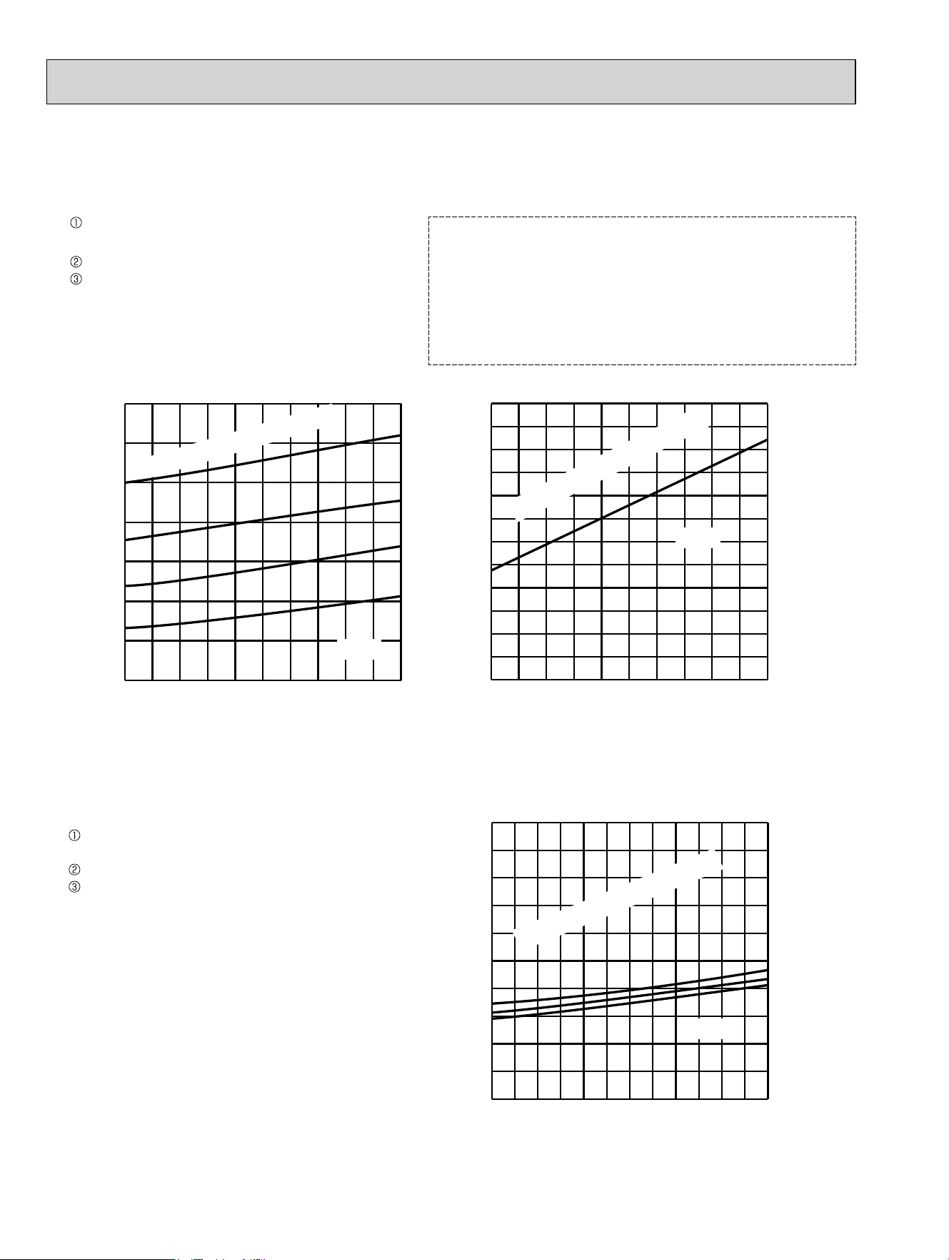
62
12. 24-class unit in single operation
(OUTDOOR UNIT: MXZ-5C42NA MXZ-3C30NAHZ
MXZ-5C42NA2 MXZ-3C30NAHZ2)
(1) COOL operation(1) COOL operation
Data is based on the condition of indoor
humidity 50%
Air flow speed: High
Inverter output frequency: 18 Hz
(2) HEAT operation
<How to work fixed-frequency operation>
1. Set emergency switch to COOL or HEAT. The switch is located
on indoor unit.
2. Press emergency run ON/OFF button.
3. Compressor starts running at 18 Hz (COOL) or 20 Hz (HEAT).
4. Indoor fan runs at High speed and continues for 30 minutes.
5. To cancel this operation, press emergency run ON/OFF button
or any button on remote controller.
65 70 75 80 85 90 95 100 105 110 115
130
140
150
170
190
200
160
180
$PELHQWWHPSHUDWXUHÛ)
Û)
,QGRRU'U\EXOEWHPSHUDWXUHÛ)
65 70 75 80 85 90 95 100 105 110 115
0.0
1.0
2.0
3.0
4.0
5.0
6.0
$PELHQWWHPSHUDWXUHÛ)
Û)
Û)
15 20 25 30 35 40 45 50 55 60 65 70 75
2.0
3.0
4.0
5.0
6.0
7.0
$PELHQWWHPSHUDWXUHÛ)
Outdoor low pressure
2XWGRRUXQLWFXUUHQW$
2XWGRRUXQLWFXUUHQW$
20 Hz
36,*
18 Hz
18 Hz
,QGRRU'U\EXOEWHPSHUDWXUHÛ)
,QGRRU'U\EXOEWHPSHUDWXUHÛ)
86
80
75
70
86
80
75
70
65
75
70
Data is based on the condition of outdoor
humidity 75%.
Set air flow to High speed.
Inverter output frequency is 20 Hz.
OBH702C
63
ACTUATOR CONTROL
9
MXZ-3C24NA MXZ-3C30NA MXZ-4C36NA MXZ-5C42NA
MXZ-2C20NAHZ MXZ-3C24NAHZ MXZ-3C30NAHZ
MXZ-3C24NA2 MXZ-3C30NA2 MXZ-4C36NA2 MXZ-5C42NA2
MXZ-2C20NAHZ2 MXZ-3C24NAHZ2 MXZ-3C30NAHZ2
Relation between main sensor and actuator
Sensor Purpose
Actuator
Compressor LEV
Outdoor
fan motor
4-way valve
2-way solenoid
valve
Defrost
heater
(MXZ-5C42NA
MXZ-2C20NAHZ
MXZ-3C24NAHZ
MXZ-3C30NAHZ
MXZ-5C42NA2
MXZ-2C20NAHZ2
MXZ-3C24NAHZ2
MXZ-3C30NAHZ2)
(MXZ-2C20NAHZ
MXZ-3C24NAHZ
MXZ-3C30NAHZ
MXZ-2C20NAHZ2
MXZ-3C24NAHZ2
MXZ-3C30NAHZ2)
Discharge temperature
thermistor
Protection
○○ ○
Indoor coil temperature
thermistor
Cooling: Coil frost
prevention
○○
Heating: High pres-
sure protection
○○
Defrost thermistor Heating: Defrosting
○○○○
Fin temperature
thermistor
Protection
○○
Ambient temperature
thermistor
Control/Protection
○○○ ○
Heating: Defrosting
(Heater)
○
Outdoor heat exchanger
temperature thermistor
Cooling: Control/
Protection
○○○ ○
Capacity code Control
○○
OBH702C
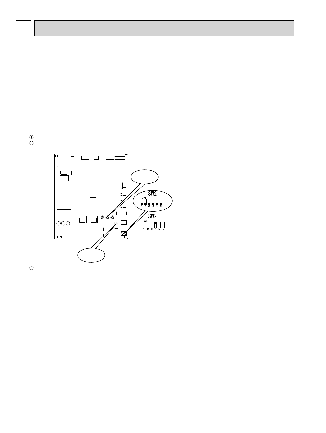
64
10-1. PRE-HEAT CONTROL
If moisture gets into the refrigerant cycle, or when refrigerant is liquefied and collected in the compressor, it may interfere
the start-up of the compressor.
To improve start-up condition, the compressor is energized even while it is not operating.
This is to generate heat at the winding.
The compressor uses about 50 W when pre-heat control is turned ON.
Pre-heat control is ON at initial setting.
[How to deactivate pre-heat control]
Turn OFF the power supply for the air conditioner before making the setting.
Set the "4" of SW2 on the outdoor control P.C. board to ON to deactivate pre-heat control function.
Turn ON the power supply for the air conditioner.
NOTE: Pre-heat control will be turned OFF when the breaker is turned OFF.
SERVICE FUNCTIONS
10
MXZ-3C24NA MXZ-3C30NA MXZ-4C36NA MXZ-5C42NA
MXZ-2C20NAHZ MXZ-3C24NAHZ MXZ-3C30NAHZ
MXZ-3C24NA2 MXZ-3C30NA2 MXZ-4C36NA2 MXZ-5C42NA2
MXZ-2C20NAHZ2 MXZ-3C24NAHZ2 MXZ-3C30NAHZ2
Outdoor control P.C. board
SW871
LED
OBH702C
65
10-2. AUTO LINE CORRECTING
Outdoor unit has an auto line correcting function which automatically detects and corrects improper wiring or piping.
Improper wiring or piping can be automatically detected by pressing the piping/wiring correction switch (SW871).
When improper wiring or piping is detected, wiring lines are corrected.
This will be completed in about 10 to 20 minutes.
[How to activate this function]
&KHFNWKDWRXWVLGHWHPSHUDWXUHLVDERYHÛ)
7KLVIXQFWLRQGRHVQRWZRUNZKHQRXWVLGHWHPSHUDWXUHLVQRWDERYHÛ)
2. Check that the stop valves of the liquid pipe and gas pipe are open.
3. Check that the wiring between indoor and outdoor unit is correct.
(If the wiring is not correct, this function does not work.)
4. Turn ON the power supply and wait at least 1 minute.
5. Press the piping/wiring correction switch (SW871) on the outdoor control P.C. board.
Do not touch energized parts.
6. Press the switch to cancel.
NOTE : Indoor unit cannot be operated while this function is activated.
When this function is activated while indoor unit is operating, the operation will be stopped.
Operate indoor unit after the auto line correcting is finished.
Pressing the switch during detection cancels this function.
Make sure that the valves are open and the pipes are not collapsed or clogged.
LED indication after cancel :
LED1 (Red)
Lighted
LED indication during detection:
LED indication after detection:
LED2 (Yellow)
Lighted
LED3 (Green)
Once
LED1 (Red)
Lighted
LED2 (Yellow)
Lighted
LED3 (Green)
Not lighted
LED1 (Red)
Lighted
Once
LED2 (Yellow)
Not lighted
Once
Other indications
LED3 (Green)
Lighted
Once
Completed (Problem corrected/ nomal)
Not completed (Detection failed)
5HIHUWR6$)(7<35(&$87,216:+(1/('%/,1.6
located behind the service panel.
Indication
Press the switch for more than 5 seconds.
LED will show the record of auto correcting for about 30 seconds as shown in the table below:
NOTE : Activate this function to confirm the correct wiring after replacing the outdoor control P.C. board.
(Previous records are deleted when the outdoor control P.C. board is replaced.)
The record cannot be shown if auto line correcting is not canceled (Refer to "How to activate this function").
LED1 (Red)
Once
3 times
LED2 (Yellow)
Once
3 times
LED3 (Green)
Lighted
Lighted
Not corrected
Corrected
Number of blinks
Wiring line
The record of auto line correcting can be confirmed in the following way:
OBH702C
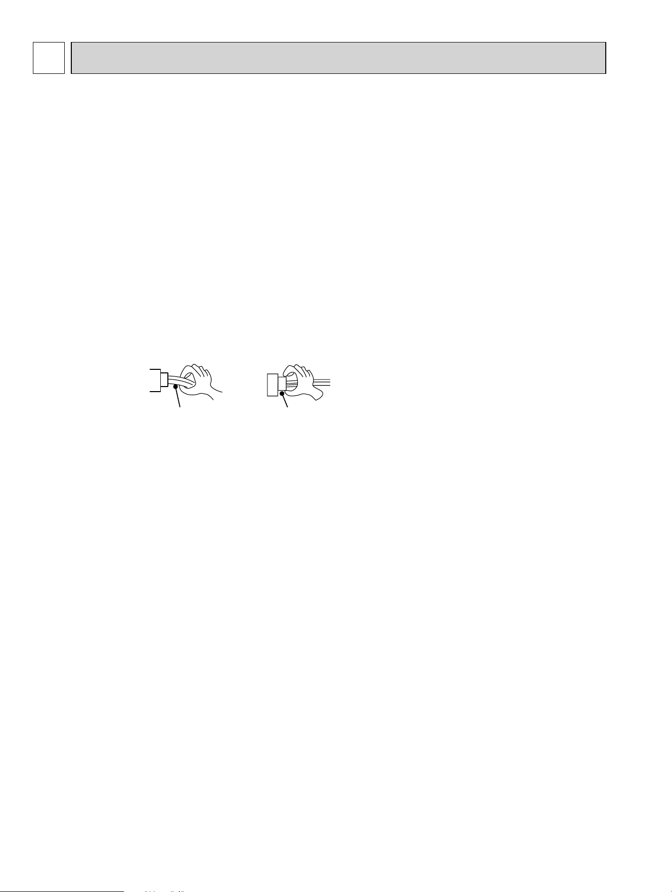
66
11
3. Troubleshooting procedure
1) Check if the OPERATION INDICATOR lamp on the indoor unit is flashing on and off to indicate an abnormality. To
make sure, check how many times the OPERATIONAL INDICATOR lamp is flashing on and off before starting service
work.
2) When the outdoor control P.C. board seems to be defective, check the copper foil pattern for disconnection and the
components for bursting and discoloration.
3) When troubleshooting, refer to 11-2, 11-3 and 11-4.
Lead wiring
Connector housing
<Incorrect>
<Correct>
11-1. CAUTIONS ON TROUBLESHOOTING
1. Before troubleshooting, check the following:
1) Check the power supply voltage.
2) Check the indoor/outdoor connecting wire for miswiring.
2. Take care of the following during servicing.
1) Before servicing the air conditioner, be sure to turn OFF the unit first with the remote controller, and then after confirm-
ing the horizontal vane is closed, turn OFF the breaker and/or disconnect the power plug.
2) Be sure to turn OFF the power supply before removing the front panel, the cabinet, the top panel, and the outdoor
control P.C. board.
3) When removing the electrical parts, be careful of the residual voltage of smoothing capacitor.
4) When removing the electronic control P.C. board, hold the edge of the board with care NOT to apply stress on the
components.
5) When connecting or disconnecting the connectors, hold the connector housing. DO NOT pull the lead wires.
TROUBLESHOOTING
11-2. FAILURE MODE RECALL FUNCTION
This air conditioner can memorize the abnormal condition which has occurred once.
Even though LED indication listed on the troubleshooting check table (11-4) disappears, the memorized failure details
can be recalled.
1. Flow chart of failure mode recall function for the indoor/outdoor unit
Refer to the service manual of indoor unit.
MXZ-3C24NA MXZ-3C30NA MXZ-4C36NA MXZ-5C42NA
MXZ-2C20NAHZ MXZ-3C24NAHZ MXZ-3C30NAHZ
MXZ-3C24NA2 MXZ-3C30NA2 MXZ-4C36NA2 MXZ-5C42NA2
MXZ-2C20NAHZ2 MXZ-3C24NAHZ2 MXZ-3C30NAHZ2
OBH702C
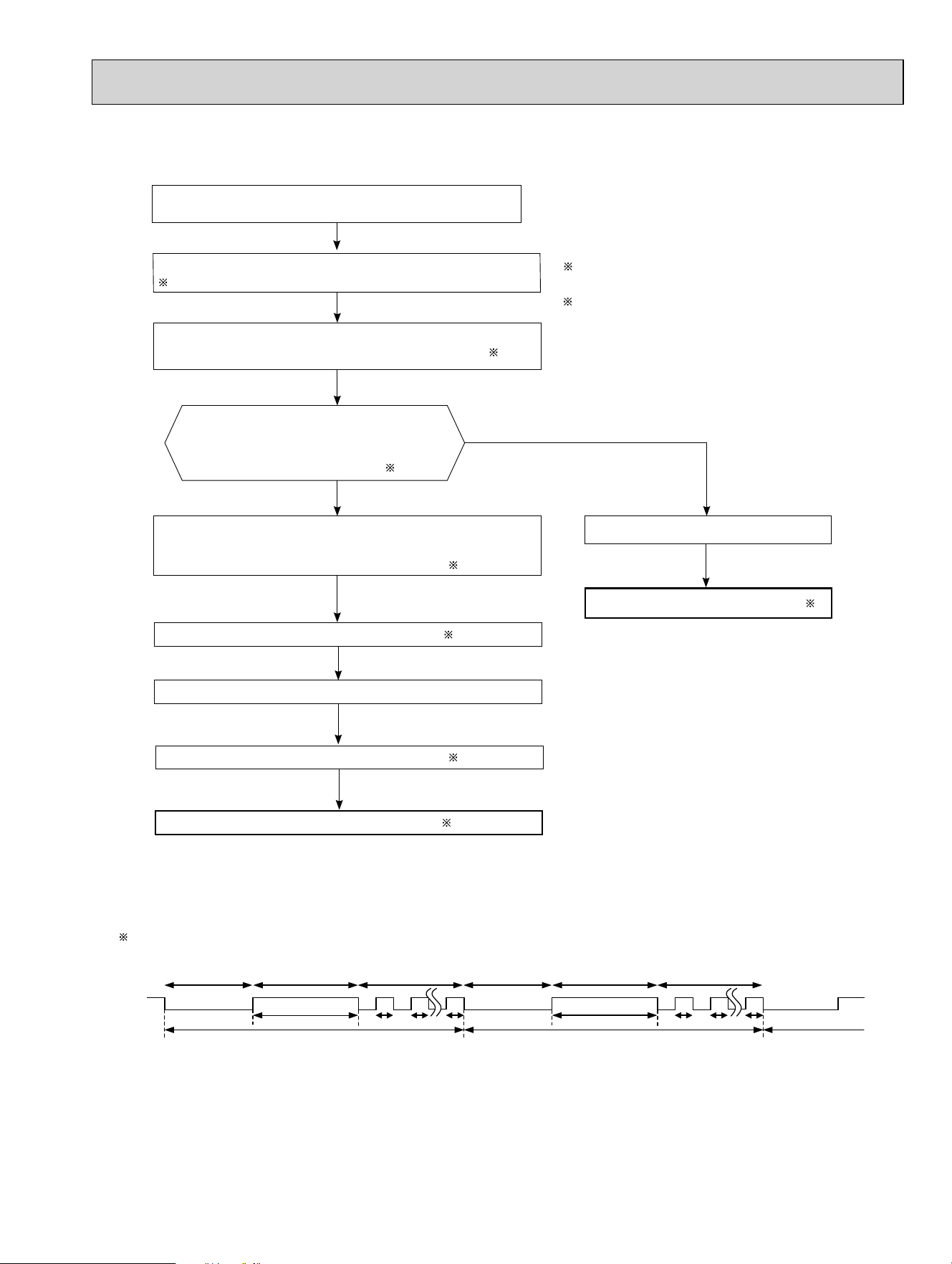
67
2. Flow chart of the detailed outdoor unit failure mode recall function
2.Blinking pattern when outdoor unit is abnormal:
ON
OFF
No beep
Beeps
Repeated cycle
2.5-second OFF 3-second ON
Blinking at 0.5-
second interval
No beep Beeps
Repeated cycle
2.5-second OFF 3-second ON
Blinking at 0.5-
second interval
Repeated cycle
Does the OPERATION INDICATOR lamp on the
indoor unit blink at the interval of 0.5 seconds?
Blinks: The outdoor unit is abnormal. Beep is emit-
ted at the same timing as the blinking of the
OPERATION INDICATOR lamp.
2
Yes
(Blinks
)
No
(OFF)
The outdoor unit might be abnormal.
Check if outdoor unit is abnormal according to the following procedures.
Operational procedure
Make sure that the remote controller is set to the failure mode recall function.
3
With the remote controller headed towards the indoor unit, press the TEM-
PERATURE buttons to adjust the set temperature to 77°F (25°C).
1
1 Regardless of normal or abnormal condition, 2 short
beeps are emitted as the signal is received.
The outdoor unit is abnormal.
Check the blinking pattern, and identify the abnormal point by referring to the
outdoor unit failure mode table (11-2.3.).
Make sure to check at least 2 consecutive blinking cycles.
2
Repair the failure parts.
The outdoor unit is normal.
Release the failure mode recall function. 3
NOTE: 1. Make sure to release the failure mode recall function after it is set up, otherwise the unit cannot operate properly.
2. If the abnormal condition is not deleted from the memory, the last abnormal condition is kept memorized.
Delete the memorized abnormal condition. 3
Release the failure mode recall function. 3
3 Refer to the service manual of indoor unit.
Release the failure mode recall function. 3
OBH702C
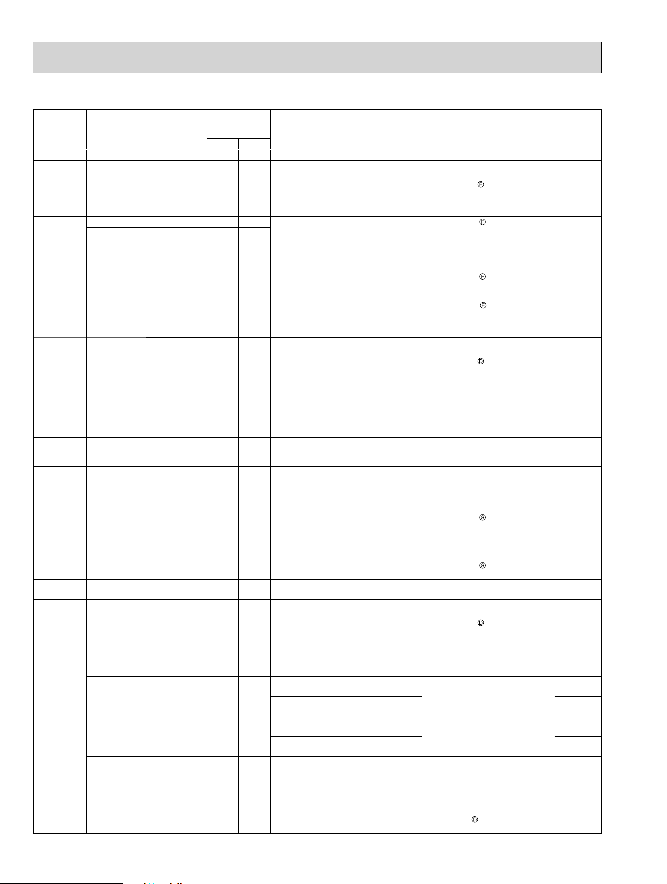
68
3. Outdoor unit failure recall mode table
The left lamp of
OPERATION IN-
DICATOR lamp
(Indoor unit)
Abnormal point
(Failure mode/protection)
LED indication
(Outdoor P.C.
board)
Condition Remedy
Indoor/
outdoor unit
failure mode
recall function
LED 1 LED 2
OFF None (Normal) Lighted Lighted
2-time fl ash Outdoor power system Lighted Lighted Overcurrent protection cut-out operates
3 consecutive times within 1 minute after
the compressor gets started, or converter
protection cut-out or bus-bar voltage
protection cut-out operates 3 consecutive
times within 3 minutes after start-up.
• Check the connection of the com-
pressor connecting wire.
• Refer to 11-6.
"How to check inverter/compres-
sor".
• Check the stop valve.
○
3-time fl ash Discharge temperature thermistor
Lighted Once
A thermistor shorts or opens during
compressor running.
• Refer to 11-6. "Check of outdoor
thermistors".
○
Defrost thermistor
Lighted Once
Ambient temperature thermistor
Lighted Twice
Fin temperature thermistor
Lighted 3 times
P.C. board temperature thermistor
Lighted 4 times
• Replace the outdoor control P.C. board.
Outdoor heat exchanger tem-
perature thermistor
Lighted 9 times • Refer to 11-6. "Check of outdoor
thermistors".
4-time fl ash Overcurrent Once Not
lighted
21 A (MXZ-3C24/3C30/4C36NA, MXZ-3C24/
3C30/4C36NA2)/28 A (MXZ-5C42NA, MXZ-
2C20/3C24/3C30NAHZ, MXZ-5C42NA2,
MXZ-2C20/3C24/3C30NAHZ2) current flows
into power module.
• Reconnect compressor connector.
• Refer to 11-6.
"How to check in-
verter/compressor".
• Check the stop valve.
—
5-time fl ash Discharge temperature Lighted Lighted
The discharge temperature exceeds 222.8°F
(MXZ-3C24/3C30/4C36NA, MXZ-3C24/3C30/
4C36NA2)/240.8°F (MXZ-2C20/3C24/3C30
NAHZ, 5C42NA, MXZ-2C20/3C24/3C30
NAHZ2, 5C42NA2) during operation.
Compressor can restart if discharge tempera-
ture thermistor reads 203°F (MXZ-3C24/3C30
/4C36NA, MXZ-3C24/3C30/4C36NA2)/212°F
(MXZ-2C20/3C24/3C30NAHZ, 5C42NA,
MXZ-2C20/3C24/3C30NAHZ2, 5C42NA2) or
less 3 minutes later.
• Check refrigerant circuit and refrig-
erant amount.
• Refer to 11-6.
"Check of LEV".
—
6-time fl ash High pressure Lighted Lighted
The outdoor heat exchanger temperature ex-
ceeds 158°F during cooling or the indoor gas
pipe temperature exceeds 158°F during heating.
• Check refrigerant circuit and refrig-
erant amount.
• Check the stop valve.
—
7-time fl ash Fin temperature 3 times Not
lighted
The fin temperature exceeds 190°F (MXZ-
3C24/3C30/4C36NA, MXZ-3C24/3C30/
4C36NA2)/192°F (MXZ-2C20/3C24/
3C30NAHZ, 5C42NA, MXZ-2C20/3C24/3C30
NAHZ2, 5C42NA2) during operation.
• Check around outdoor unit.
• Check outdoor unit air passage.
• Refer to 11-6.
"Check of outdoor
fan motor".
—
P.C. board temperature 4 times Not
lighted
The P.C. board temperature exceeds 152°F
(MXZ-3C24/3C30/4C36NA, MXZ-3C24/3C30/
4C36NA2)/189°F (MXZ-2C20/3C24/3C30
NAHZ, 5C42NA, MXZ-2C20/3C24/3C30
NAHZ2, 5C42NA2) during operation.
8-time fl ash Outdoor fan motor Lighted Lighted A failure occurs 3 consecutive times within
30 seconds after the fan gets started.
• Refer to 11-6. "Check of outdoor
fan motor".
—
9-time fl ash Outdoor control system Lighted 5 times Nonvolatile memory data cannot be read
properly.
• Replace the outdoor control P.C.
board.
○
10-time fl ash Low discharge temperature
protection
Lighted Lighted
The frequency of the compressor is kept 80
Hz or more and the discharge temperature is
kept under 102.2°F for more than 20 minutes.
• Check refrigerant circuit and refrig-
erant amount.
• Refer to 11-6.
"Check of LEV".
—
11-time fl ash Communication error
between P.C. boards
Lighted 6 times
Communication error occurs between the out-
door control P.C. board and outdoor power P.C.
board for more than 10 seconds.
• Check the connecting wire between
outdoor control P.C. board and out-
door power P.C. board.
—
The communication between boards protec-
tion cut-out operates 2 consecutive times.
○
Current sensor Lighted 7 times
A short or open circuit is detected in the cur-
rent sensor during compressor operating.
—
—
Current sensor protection cut-out oper-
ates 2 consecutive times.
○
Zero cross detecting circuit 5 times Not
lighted
Zero cross signal cannot be detected
while the compressor is operating.
• Check the connecting wire among
outdoor control P.C. board and out-
door power P.C. board.
—
The protection cut-out of the zero cross de-
tecting circuit operates 10 consecutive times.
○
Converter 5 times Not
lighted
A failure is detected in the operation of the
converter during operation.
• Check the voltage of power supply.
• Replace the outdoor power P.C.
board.
—
Bus-bar voltage 6 times Not
lighted
The bus-bar voltage exceeds 400 V or
falls to low level during compressor oper-
ating.
• Check the voltage of power supply.
• Replace the outdoor control P.C.
board.
15-time fl ash LEV and drain pump Lighted Lighted The indoor unit detects an abnormality in
the LEV and drain pump.
• Refer to 11-6. "Check of LEV".
• Check the drain pump of the indoor unit.
—
NOTE: Blinking patterns of this mode differ from the ones of
TROUBLESHOOTING CHECK TABLE (11-4.).
OBH702C
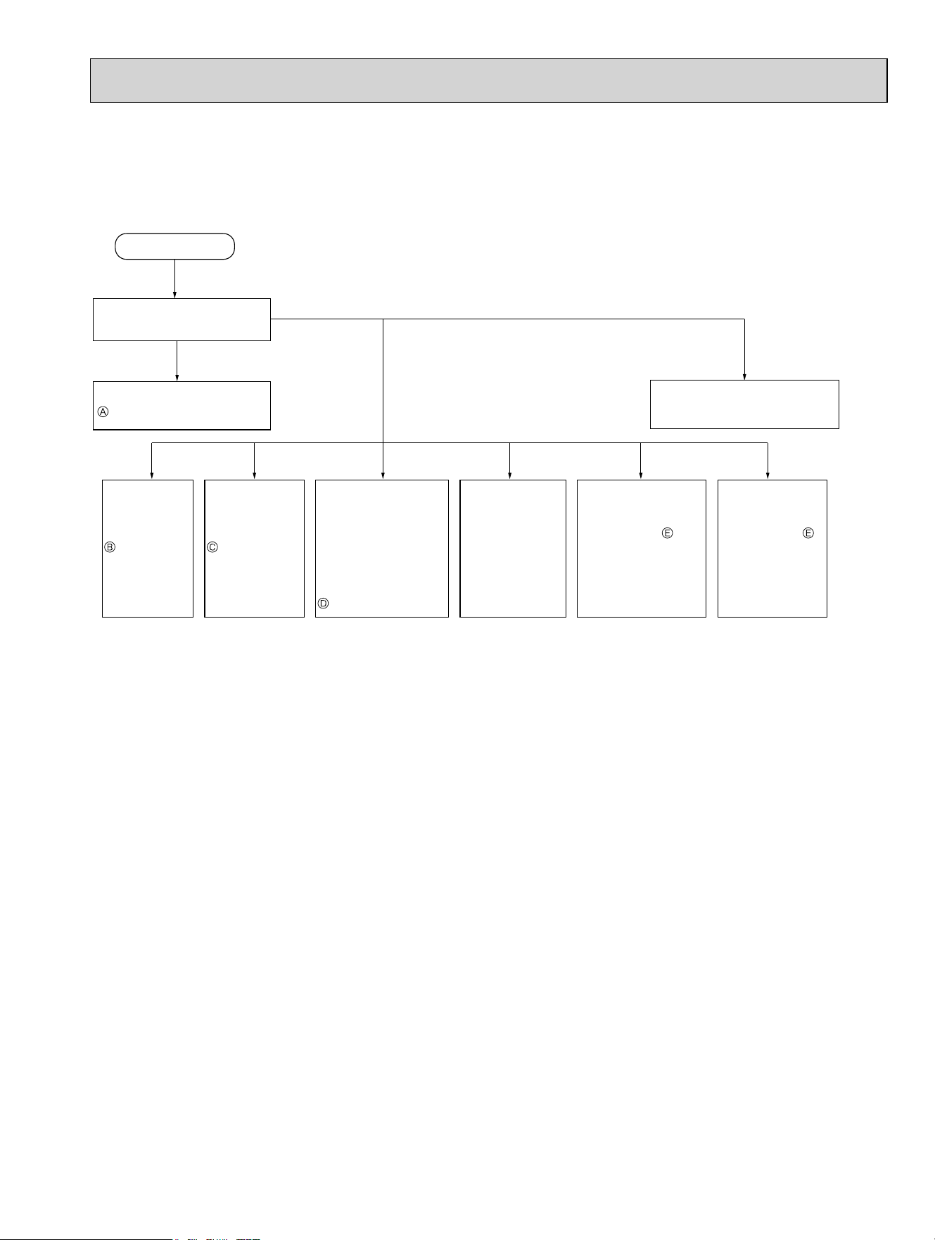
69
Operation start
Check the outdoor unit
LED indicator.
Refer to 11-6.
"Check of power supply".
,QGRRUXQLW
serial signal
error
Refer to 11-6.
"How to
check
miswiring and
serial signal
error".
&22/RU
HEAT
operation only
Refer to 11-6.
"Check of
R.V. coil".
:KHQFRROLQJ
room is not
cool.
Refer to 11-6.
"How to check
inverter/
compressor".
:KHQFRROLQJKHDW
exchanger of
non-operating indoor
unit frosts.
:KHQKHDWLQJQRQ
operating indoor unit
gets warm.
Refer to 11-6.
"Check of LEV".
:KHQKHDWLQJ
room does not get
warm.
Refer to 11-6.
"How to check
inverter/compressor".
&KHFNPLVSLSLQJ
shortage of capacity.
:KHQFRROLQJ
dew drops in the
non-operating
indoor unit.
Check of
miss-piping.
Refer to 11-4.
"Troubleshooting check table".
Both LED1 and
LED2 are OFF.
Both LED1 and
LED2 are lighting.
LED1 or LED2
has blinked.
11-3. INSTRUCTION OF TROUBLESHOOTING
• Check the indoor unit with referring to the indoor unit service manual, and confirm that there is any problem in the indoor
unit.
Then, check the outdoor unit with referring to this page.
OBH702C
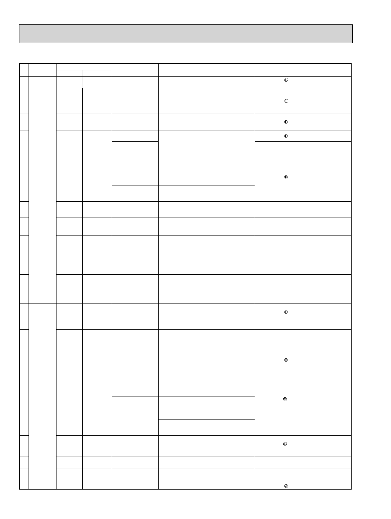
70
11-4. TROUBLESHOOTING CHECK TABLE
No. Symptom
Indication
Abnormal point / Con-
dition
Condition Remedy
LED1(Red) LED2(Yellow)
1 Outdoor
unit does
not operate.
Lighted Once LEV and drain pump
The indoor unit detects an abnormality in the LEV
and drain pump.
• Refer to 11-6.
"Check of LEV".
• Check the drain pump of the indoor unit.
2
Lighted Twice
Outdoor power
system
Overcurrent protection cut-out operates 3 consecu-
tive times within 1 minute after the compressor
gets started, or converter protection cut-out or bus-
bar voltage protection cut-out operates 3 consecu-
tive times within 3 minutes after start-up.
• Check the connection of the compressor connect-
ing wire.
• Refer to 11-6.
"How to check inverter/compres-
sor".
• Check the stop valve.
3
Lighted 3 times
Discharge temperature
thermistor
A short circuit is detected in the thermistor during
operation, or an open circuit is detected in the
thermistor after 10 minutes of compressor start-up.
• Refer to 11-6.
"Check of outdoor thermistors".
4
Lighted 4 times
Fin temperature
thermistor
A short or open circuit is detected in the thermistor
during operation.
• Refer to 11-6.
"Check of outdoor thermistors".
P. C. board tempera-
ture thermistor
• Replace the outdoor control P.C. board.
5
Lighted 5 times
Ambient temperature
thermistor
A short or open circuit is detected in the thermistor
during operation.
• Refer to 11-6.
"Check of outdoor thermistors".
Outdoor heat ex-
changer temperature
thermistor
A short circuit is detected in the thermistor during
operation, or an open circuit is detected in the
thermistor after 5 minutes (in cooling) and 10
minutes (in heating) of compressor start-up.
Defrost thermistor
A short circuit is detected in the thermistor during
operation, or an open circuit is detected in the
thermistor after 5 minutes of compressor start-up.
6
Lighted 6 times
Zero cross detecting
circuit (Outdoor control
P.C. board)
Zero cross signal cannot be detected. • Replace the outdoor control P.C. board.
7 Lighted 7 times Outdoor control system
The nonvolatile memory data cannot be read properly.
• Replace the outdoor control P.C. board.
8
Lighted 8 times Current sensor
Current sensor protection cut-out operates 2 con-
secutive times.
• Replace the outdoor power P.C. board.
9
Lighted 11 times
Communication error
between P.C. boards
The communication protection cut-out between
boards operates 2 consecutive times.
• Check the connecting wire between outdoor con-
trol P.C. board and outdoor power P.C. board.
M-NET communication
error
M-NET adapter P.C. board detects an abnormality
in the communication error.
• Check the connecting wire between M-NET
adapter P.C. board and outdoor control P.C.
board, or terminal bed.
10
Lighted 12 times
Zero cross detecting
circuit
The protection cut-out of the zero cross detecting
circuit operates 10 consecutive times.
• Check the connecting wire among outdoor control
P.C. board and outdoor power P.C. board.
11
Lighted 13 times Current sensor
A short or open circuit is detected in the input cur-
rent detection circuit during operation.
• Replace the outdoor power P.C. board.
12
Lighted 14 times Voltage sensor
A short or open circuit is detected in the input volt-
age detection circuit during operation.
• Replace the outdoor power P.C. board.
13 Lighted 15 times Relay operation No relay operation is detected during operation. • Replace the outdoor power P.C. board.
14 'Outdoor unit
stops and
restarts
3 minutes
later' is
repeated.
Twice Not lighted
IPM protection
Overcurrent is detected after 30 seconds of com-
pressor start-up.
• Reconnect compressor connector.
• Refer to 11-6.
"How to check inverter/
compressor".
• Check the stop valve.
• Check the power module (PAM module).
Lock protection
Overcurrent is detected within 30 seconds of com-
pressor start-up.
15
3 times Not lighted
Discharge temperature
protection
The discharge temperature exceeds 222.8°F (MXZ-
3C24/3C30/4C36NA, MXZ-3C24/3C30/4C36NA2)/
240.8°F (MXZ-2C20/3C24/3C30NAHZ, 5C42NA,
MXZ-2C20/3C24/3C30NAHZ2, 5C42NA2) during
operation.
Compressor can restart if discharge temperature
thermistor reads 203°F
(MXZ-
3C24/3C30/4C36NA,
MXZ-3C24/3C30/4C36NA2)/212°F (MXZ-2C20/
3C24/3C30NAHZ, 5C42NA, MXZ-2C20/3C24/
3C30NAHZ2, 5C42NA2) or less 3 minutes later.
• Check the amount of gas and refrigerant circuit.
• Refer to 11-6.
"Check of LEV".
16
4 times Not lighted
Fin temperature
protection
The fi n temperature exceeds during operation.
•Check refrigerant circuit and refrigerant amount.
•Refer to 11-6.
"Check of outdoor fan motor".
P.C. board temperature
protection
The P.C. board temperature exceeds during opera-
tion.
17
5 times Not lighted
High-pressure
protection
High-pressure is detected with the high-pressure
switch (HPS) during operation.
• Check around of gas and the refrigerant circuit.
• Check the stop valve.
The outdoor heat exchanger temperature exceeds
158°F during cooling or the indoor gas pipe tem-
perature exceeds 158°F during heating.
18
6 times Not lighted Pre-heating protection Overcurrent is detected during pre-heating.
• Reconnect compressor connector.
• Refer to 11-6.
"How to check inverter/
compressor".
• Check the power module.
19
8 times Not lighted Converter protection
A failure is detected in the operation of the convert-
er during operation.
• Replace the outdoor power P.C. board.
20
9 times Not lighted
Bus-bar voltage
protection
The bus-bar voltage exceeds 400 V or falls to low
level during compressor operating.
• Check the voltage of power supply.
• Replace the outdoor power P.C. board or the out-
door control P.C. board.
• Refer to 11-6.
"Check of bus-bar voltage".
OBH702C
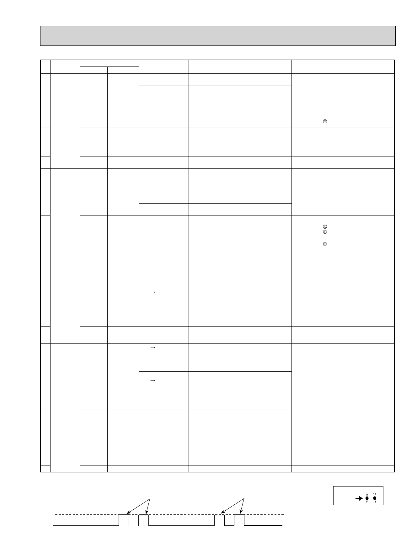
71
No. Symptom
Indication
Abnormal point / Con-
dition
Condition Remedy
LED1(Red) LED2(Yellow)
21 'Outdoor unit
stops and
restarts
3 minutes
later' is
repeated.
11 times Not lighted
Low out side tempera-
ture protection(cooling)
The ambient became 10.4°F or less.
—
Low out side tempera-
ture protection(Heating)
The ambient became 1.4°F or less. (MXZ-3C24/
3C30/4C36/5C42NA, MXZ-3C24/3C30/4C36/
5C42NA2)
The ambient became -18°F or less. (MXZ-2C20/
3C24/3C30NAHZ, MXZ-
2C20/3C24/3C30NAHZ2)
22
13 times Not lighted Outdoor fan motor
A failure occurs 3 consecutive times within 30
seconds after the fan gets started.
• Refer to 11-6.
"Check of outdoor fan motor".
23
Lighted 8 times
Current sensor protec-
tion
A short or open circuit is detected in the current
sensor during compressor operating.
• Replace the outdoor power P.C. board.
24
Lighted 11 times
Communication
between P.C. boards
protection
Communication error occurs between the outdoor
control P.C. board and outdoor power P.C. board
for more than 10 seconds.
• Check the connecting wire between outdoor con-
trol P.C. board and outdoor power P.C. board.
25
Lighted 12 times
Zero cross detecting
circuit protection
Zero cross signal cannot be detected while the
compressor is operating.
• Check the connecting wire among outdoor control
P.C. board and outdoor power P.C. board.
26 Outdoor unit
operates.
Once Lighted
Primary current protec-
tion
The input current exceeds 18.4 A (MXZ-3C24/
3C30/4C36NA, MXZ-3C24/3C30/4C36NA2)/
26.8 A (MXZ-2C20/3C24/3C30NAHZ, 5C42NA,
MXZ-2C20/3C24/3C30NAHZ2, MXZ-5C42NA2).
These symptoms do not mean any abnormality of
the product, but check the following points.
• Check if indoor fi lters are clogged.
• Check if refrigerant is short.
• Check if indoor/outdoor unit air circulation is short
cycled.
27
Twice Lighted
High-pressure protec-
tion
The indoor gas pipe temperature exceeds 113°F
during heating.
Defrosting in cooling
The indoor gas pipe temperature falls 37.4°F or
below during cooling.
28
3 times Lighted
Discharge temperature
protection
The frequency of the compressor is kept 80 Hz or
more and the discharge temperature is kept under
122°F(COOL mode)/104°F(HEAT mode) for more
than 40 minutes.
• Check refrigerant circuit and refrigerant amount.
• Refer to 11-6.
"Check of LEV".
• Refer to 11-6.
"Check of outdoor thermistors".
29
4 times Lighted
Low discharge
temperature protection
The frequency of the compressor is kept 80 Hz or
more and the discharge temperature is kept under
102.2°F for more than 20 minutes.
• Refer to 11-6.
"Check of LEV".
• Check refrigerant circuit and refrigerant amount.
30
5 times Lighted
Cooling high-pressure
protection
The outdoor heat exchanger temperature exceeds
136.4°F during operation.
This symptom does not mean any abnormality of
the product, but check the following points.
• Check if indoor fi lters are clogged.
• Check if refrigerant is short.
•
Check if indoor/outdoor unit air circulation is short cycled.
31
7 times Lighted
High Low
Pressure bypass
valve
Cooling evaporating
temperature drop
prevention control
During cooling operation, the temperature of indoor
heat exchanger becomes 37.4°F or less within 1
hour after the compressor starts running, or it be-
comes less than 53.6°F - 60.8°F* later than that.
* It depends on the difference between the set
temperature and the room temperature.
(MXZ-2C20/3C24/3C30NAHZ, MXZ-5C42NA,
MXZ-2C20/3C24/3C30NAHZ2, MXZ-5C42NA2)
This symptom does not mean any abnormality of
the product, but check the following points.
• Check the indoor fi lters are not clogged.
• Check there is suffi cient refrigerant.
• Check the indoor/outdoor unit air circulation is not
short cycled.
32
11 times Lighted
M-NET communication
error
M-NET adapter P.C. board detects an abnormality
in the communication error.
• Check the connecting wire between M-NET
adapter P.C. board and outdoor control P.C.
board, or terminal block.
33
Outdoor
unit
operates
normally.
7 times Lighted
High Low
pressure bypass valve
High pressure protec-
tion control at start-up
of heating operation
The room temperature is 75.2°F or more when 1 or
2 unit(s) start(s) the heating operation.
(MXZ-2C20/3C24/3C30NAHZ, MXZ-5C42NA,
MXZ-2C20/3C24/3C30NAHZ2, MXZ-5C42NA2)
This symptom does not mean any abnormality of
the product.
High
Low
pressure bypass valve
Compressor oil temper-
ing control at start-up of
heating operation
Both the following are true:
• The outside temperature is 28.4°F or less when
the heating operation is started.
• [(Discharge temperature) - (Indoor heat exchang-
er temperature)] < 9°F
(MXZ-2C20/3C24/3C30NAHZ, MXZ-5C42NA,
MXZ-2C20/3C24/3C30NAHZ2, MXZ-5C42NA2)
34
8 times Lighted
Cooling evaporating
temperature
protection
During cooling operation, the temperature of
indoor heat exchanger becomes 44.6°F - 51.8°F*
or less within 1 hour after the compressor
starts running, or it becomes 48.2°F - 62.6°F* or
less later than that.
* It depends on the indoor unit type/model or the
difference between the set temperature and the
room temperature.
35
9 times Lighted Inverter check mode
The unit is operated with emergency operation
switch.
—
36 Lighted Lighted Normal
——
NOTE: 1. The location of LED is illustrated at the right figure. Refer to 11-7.1.
2. LED is lighted during normal operation.
The flashing frequency shows the number of times the LED blinks after every 2.5-second OFF.
(Example) When the flashing frequency is “2”.
ON
OFF
2.5-second OFF
2.5-second OFF
0.5-second ON
0.5-second ON
LED1
LED2
Lighted
Outdoor control P.C. board
(Parts side)
OBH702C
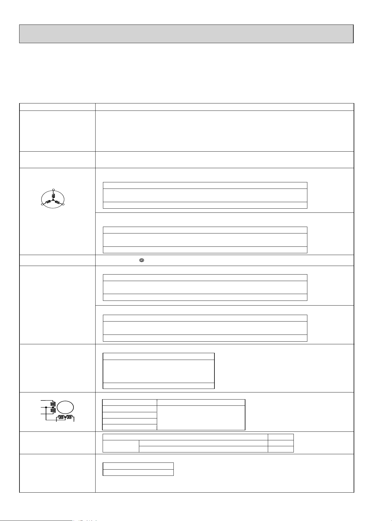
72
11-5. TROUBLE CRITERION OF MAIN PARTS
MXZ-3C24NA MXZ-3C30NA MXZ-4C36NA MXZ-5C42NA
MXZ-2C20NAHZ MXZ-3C24NAHZ MXZ-3C30NAHZ
MXZ-3C24NA2 MXZ-3C30NA2 MXZ-4C36NA2 MXZ-5C42NA2
MXZ-2C20NAHZ2 MXZ-3C24NAHZ2 MXZ-3C30NAHZ2
W
U
V
WHT
RED
BLK
LEV
WHT
RED
YLW
ORN
BLU
Linear expansion valve
37.4 - 53.9
NormalColor of lead wire
WHT - RED
RED - ORN
YLW - RED
RED - BLU
High pressure switch
(HPS)
Pressure Normal
HPS
537 ± 22 PSIG
696 PSIG
Open
Close
+7
- 15
Discharge temperature
thermistor (RT62)
Measure the resistance using a tester. (Part temperature: 14°F - 104°F)
Measure the resistance using a tester. (Part temperature: 14°F - 104°F)
Part name Check method and criterion
Measure the resistance between terminals using a tester.
(Winding temperature: 14°F - 104°F)
Compressor
Outdoor fan motor
R.V. coil
Defrost thermistor (RT61)
Fin temperature
thermistor (RT64)
Ambient temperature
thermistor (RT65)
Outdoor heat exchanger
temperature thermistor (RT68)
Measure the resistance with a tester.
Refer to 11-7. “Test point diagram and voltage”, 1. ”Outdoor control P.C.board”,
2. ”Outdoor power P.C. board”, for the chart of thermistor.
Measure the resistance with a tester.
Before measurement, hold the thermistor with your hands to warm it up.
Refer to 11-7. “Test point diagram and voltage”,1. ”Outdoor control P.C. board” for the chart of thermistor.
MXZ-3C24NA MXZ-3C30NA MXZ-4C36NA
MXZ-3C24NA2 MXZ-3C30NA2 MXZ-4C36NA2
MXZ-3C24NA MXZ-3C30NA MXZ-4C36NA
MXZ-3C24NA2 MXZ-3C30NA2 MXZ-4C36NA2
Normal (Each phase)
NN
Normal (Each phase)
Measure the resistance between terminals using a tester.
(Winding temperature: 14°F - 104°F)
MXZ-5C42NA MXZ-2C20NAHZ MXZ-3C24NAHZ MXZ-3C30NAHZ
MXZ-5C42NA2 MXZ-2C20NAHZ2 MXZ-3C24NAHZ2 MXZ-3C30NAHZ2
MXZ-5C42NA MXZ-2C20NAHZ MXZ-3C24NAHZ MXZ-3C30NAHZ
MXZ-5C42NA2 MXZ-2C20NAHZ2 MXZ-3C24NAHZ2 MXZ-3C30NAHZ2
Normal (Each phase)
NN
Normal (Each phase)
5HIHUWR
Normal
Measure the resistance using a tester. (Part temperature: 14°F - 104°F)
2-way valve solenoid coil
MXZ-5C42NA
MXZ-2C20NAHZ
MXZ-3C24NAHZ
MXZ-3C30NAHZ
MXZ-5C42NA2
MXZ-2C20NAHZ2
MXZ-3C24NAHZ2
MXZ-3C30NAHZ2
Measure the resistance using a tester. (Part temperature: 14°F - 104°F)
NN
MXZ-5C42NA
MXZ-2C20NAHZ
MXZ-3C24NAHZ
MXZ-3C30NAHZ
MXZ-5C42NA2
MXZ-2C20NAHZ2
MXZ-3C24NAHZ2
MXZ-3C30NAHZ2
Normal
Measure the resistance using a tester. (Part temperature: 14°F - 104°F)
Defrost heater
MXZ-2C20NAHZ
MXZ-3C24NAHZ
MXZ-3C30NAHZ
MXZ-2C20NAHZ2
MXZ-3C24NAHZ2
MXZ-3C30NAHZ2
0.35N - 0.50N
OBH702C
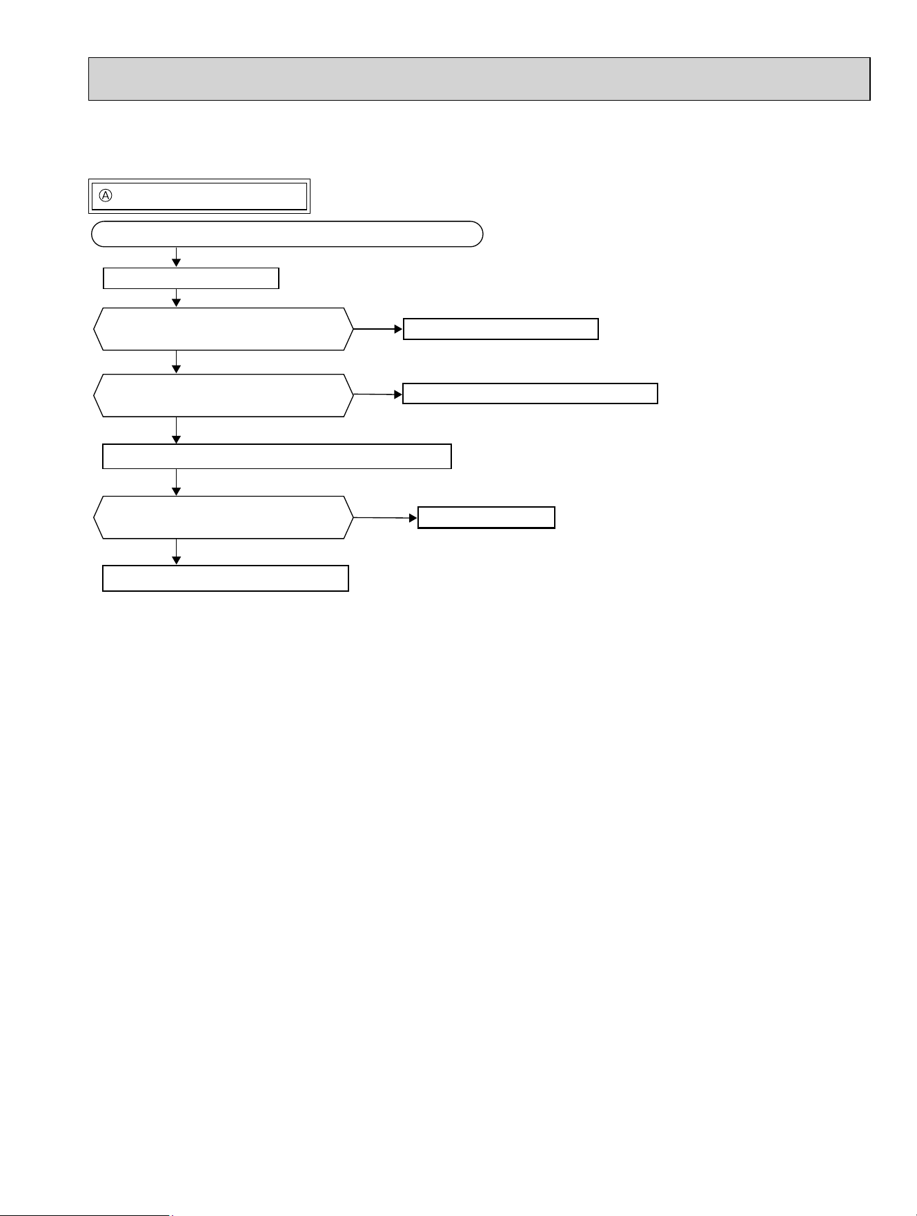
73
Check of power supply
Outdoor unit does not operate.
11-6. TROUBLESHOOTING FLOW
Turn ON the power supply.
No
Yes
Yes
No
No
Yes
Check the main power supply circuit for proper connections.
Is there voltage of 208/230 VAC in the
power supply terminal block?
Is the output voltage from the outdoor
power P.C. board 294/325 VDC?
Check the power supply cable.
Replace the outdoor power P.C. board.
Turn OFF the power supply and recconnect the reactor.
Is the reactor short-circuited?
Replace the reactor.
Replace the outdoor control P.C. board.
OBH702C
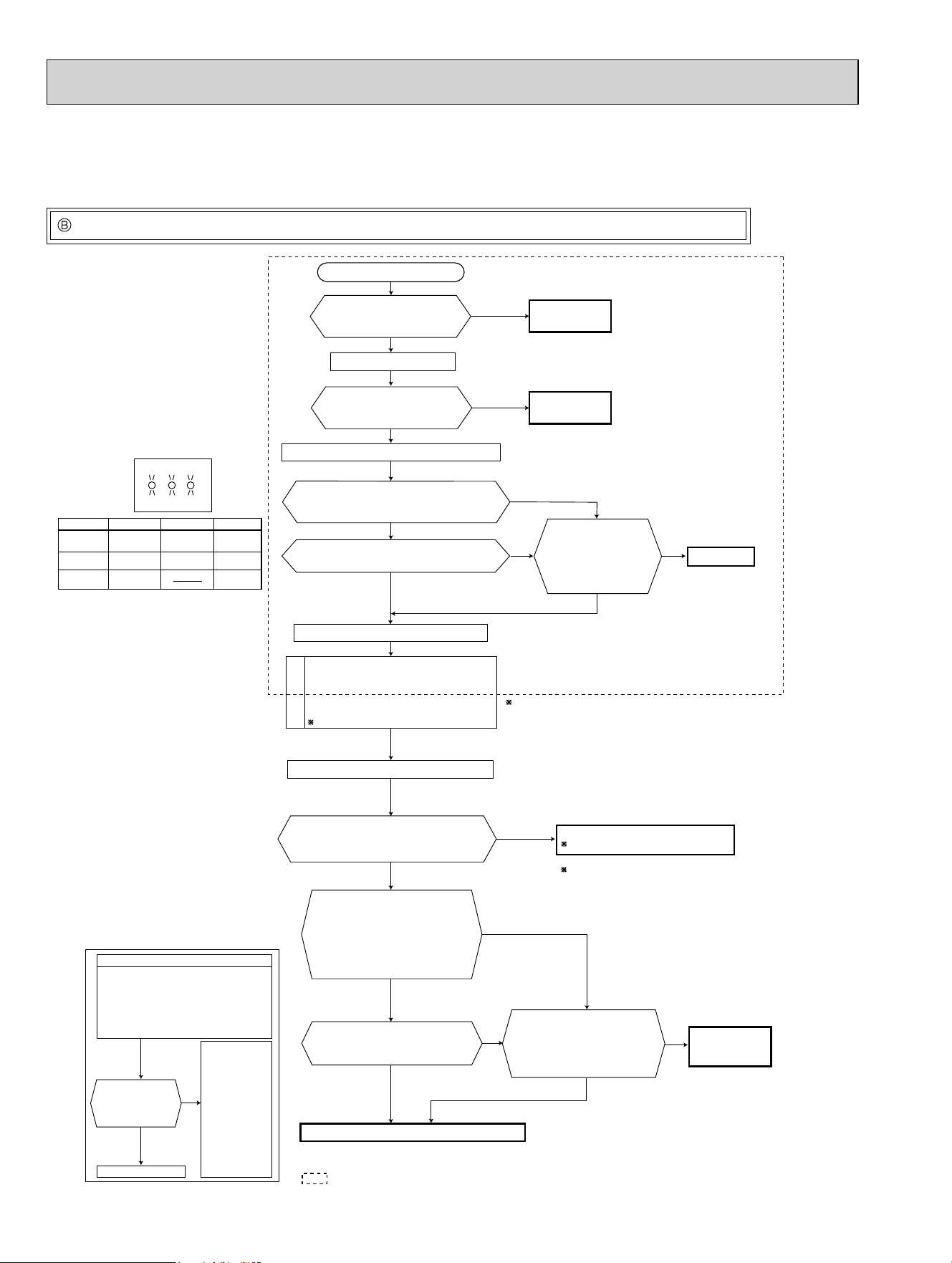
74
Is there rated voltage in
the power supply?
Is there any miswiring,
poor contact, or wire
disconnection of the
indoor/outdoor
connecting wire?
1 Miswiring may damage indoor electronic control
P.C. board during the operation.
Be sure to confirm the wiring is correct before the
operation starts.
(Lighted
or
not lighted)
No
Yes
No
Yes
Yes
No
Yes
No
Be sure to release the failure-mode
recall function after checking.
No
No
Yes
No
Yes
Yes
Yes
No
Yes
Refer to indoor unit service manual.
Turn OFF the power supply.
Turn ON the power supply.
Is there rated voltage between
outdoor terminal block S1 and
S2?
Does the left lamp of OPERATION
INDICATOR lamp light up?
<Confirmation of the power to the indoor unit>
Press EMERGENCY OPERATION switch once.
Check the power
supply.
A
Turn OFF the power supply.
Check once more if the indoor/outdoor
connecting wire is not miswiring.
Bridge the outdoor terminal block S2 and
S3.
1
B
Turn ON the power supply.
Check the wiring.
Correct them.
Turn OFF the power supply.
Remove the bridge between
outdoor terminal block S2 and S3.
Turn ON the power supply.
Is there amplitude of 10 to 20 VDC
between outdoor terminal block S2
and S3? <Confirmation of serial
signal>
Is there rated voltage between
indoor terminal block S1 and S2?
<Confirmation of power voltage>
Replace the indoor electronic control P.C. board.
2 Be careful of the residual
voltage of smoothing capacitor.
Replace the outdoor control P.C. board.
2
Is there any error of the
indoor/outdoor connecting wire,
such as the damage of the wire,
intermediate connection, poor
contact to the terminal block?
Replace the
indoor/outdoor
connecting wire.
Is serial signal
error indicated
6 minutes later?
Yes
No
· Turn OFF inverter-controlled lighting
equipment.
· Turn OFF the power supply and then
turn ON again.
· Press EMERGENCY OPERATION
switch.
B
· Reinstall
either the
unit or the
light away
from each
other.
· Attach a filter
on remote
control
receiving
section of
the indoor
unit.
A
Is serial signal error indicated 6 minutes later?
No
Does the LED on the outdoor control P.C.
board repeat "3.6-second-OFF
and 0.8-second-ON quick blinking"?
LED indication
for communication status
Communication status is indicated
by the LED.
Blinking: normal communication
Lighting: abnormal communication or
not connected
Pattern 1 and 2 is repeatedly displayed
alternately. Each pattern is displayed for
15 seconds.
NOTE: "Lighting" in the table below does not
indicate abnormal communication.
Unit status
Outdoor control P.C. board
Blinking
LED1 LED2
LED3
LED 1 LED 3LED 2
Pattern
1
2
3
Unit B
status
Unit C
status
Unit A
status
Unit D
status
Unit E
status
Not lighted
Lighted
Blinking
How to check miswiring and serial signal error (when outdoor unit does not work)
• When unit cannot operate neither by the remote controller nor by EMERGENCY OPERATION switch.
Indoor unit does not operate.
• When OPERATION INDICATOR lamp flashes ON and OFF in every 0.5-second.
Outdoor unit does not operate.
OBH702C
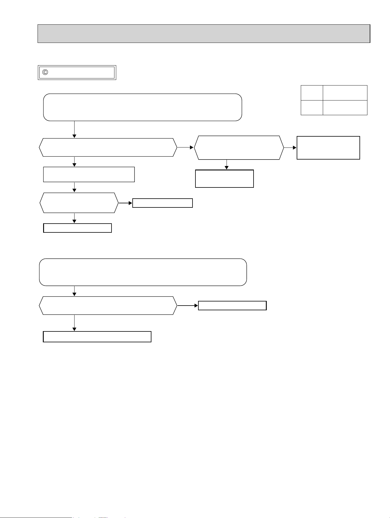
75
Check of R.V. coil
The cooling operation or heating operation does not operate.
No
Yes
No
Yes
No
Yes
No
Yes
1. Disconnect the lead wire leading to the compressor.
2. 3 minutes after turning ON the power supply, start EMERGENCY
OPERATION in COOL mode.
Is there voltage of 208/230 VAC between pin1
and pin2 at connector CN712?
Turn OFF the power supply.
Disconnect the connector CNAC2.
Replace the 4-way valve.
Replace the outdoor
control P.C. board.
Replace the R.V. coil.
Is there voltage 208/230 VAC
between the pin1 and pin3 at
connector CNAC?
Replace the outdoor
power P.C. board.
Is there normal resistance
to R.V. coil? (Refer to 11-5.)
1. Disconnect the lead wire leading to the compressor.
2. 3 minutes after turning ON the power supply, start EMERGENCY
OPERATION in HEAT mode.
Is there voltage of 208/230 VAC between pin1
and pin2 at connector CN712?
Replace the 4-way valve.
Replace the outdoor control P.C. board.
:KHQFRROLQJRSHUDWLRQGRHVQRWZRUN
:KHQKHDWLQJRSHUDWLRQGRHVQRWZRUN
CNAC
CN712
Outdoor control
P.C. board
CNAC2
Outdoor power
P.C. board
OBH702C
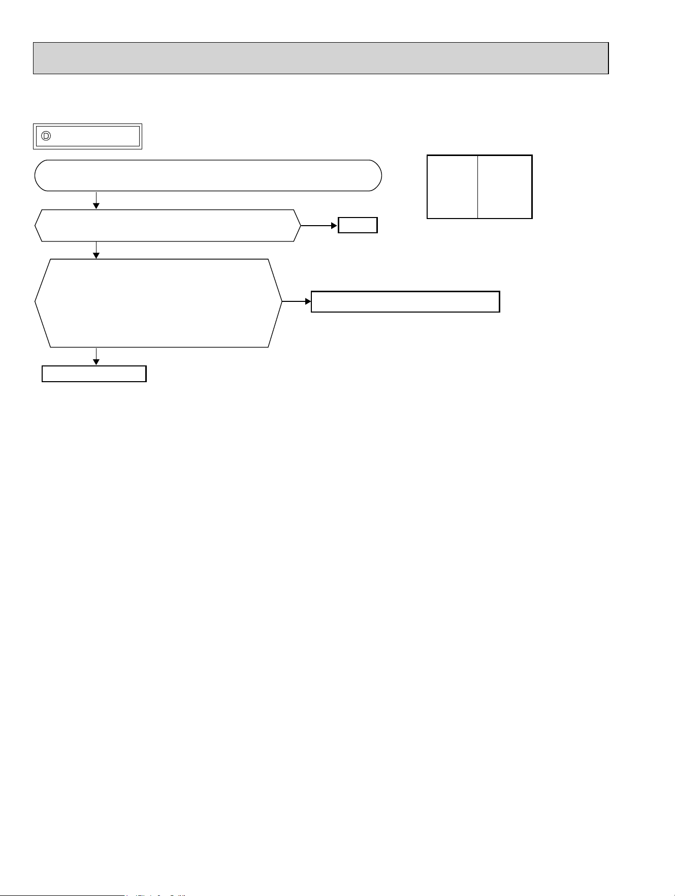
76
Check of LEV
No
Yes
No
Yes
Turn ON the power supply to the outdoor unit after checking LEV coil is
mounted to the LEV body securely.
Is "click - click" sound heard?
Or, do you feel vibration of LEV coil with your hand?
Disconnect the connectors.
CN791: LEV A, CN792: LEV B, CN793: LEV C
(MXZ-3C/4C/5C), CN794: LEV D (MXZ-4C/5C),
CN795: LEV E (MXZ-5C)
Is there normal resistance to LEV coil?
(Refer to 11-5.)
Normal
Replace the outdoor control P.C. board.
Replace LEV coil.
• When cooling, heat exchanger of non-operating indoor unit frosts.
• When heating, non-operating indoor unit gets warm.
CN791
CN792
CN793
CN794
CN795
Outdoor
control
P.C. board
OBH702C
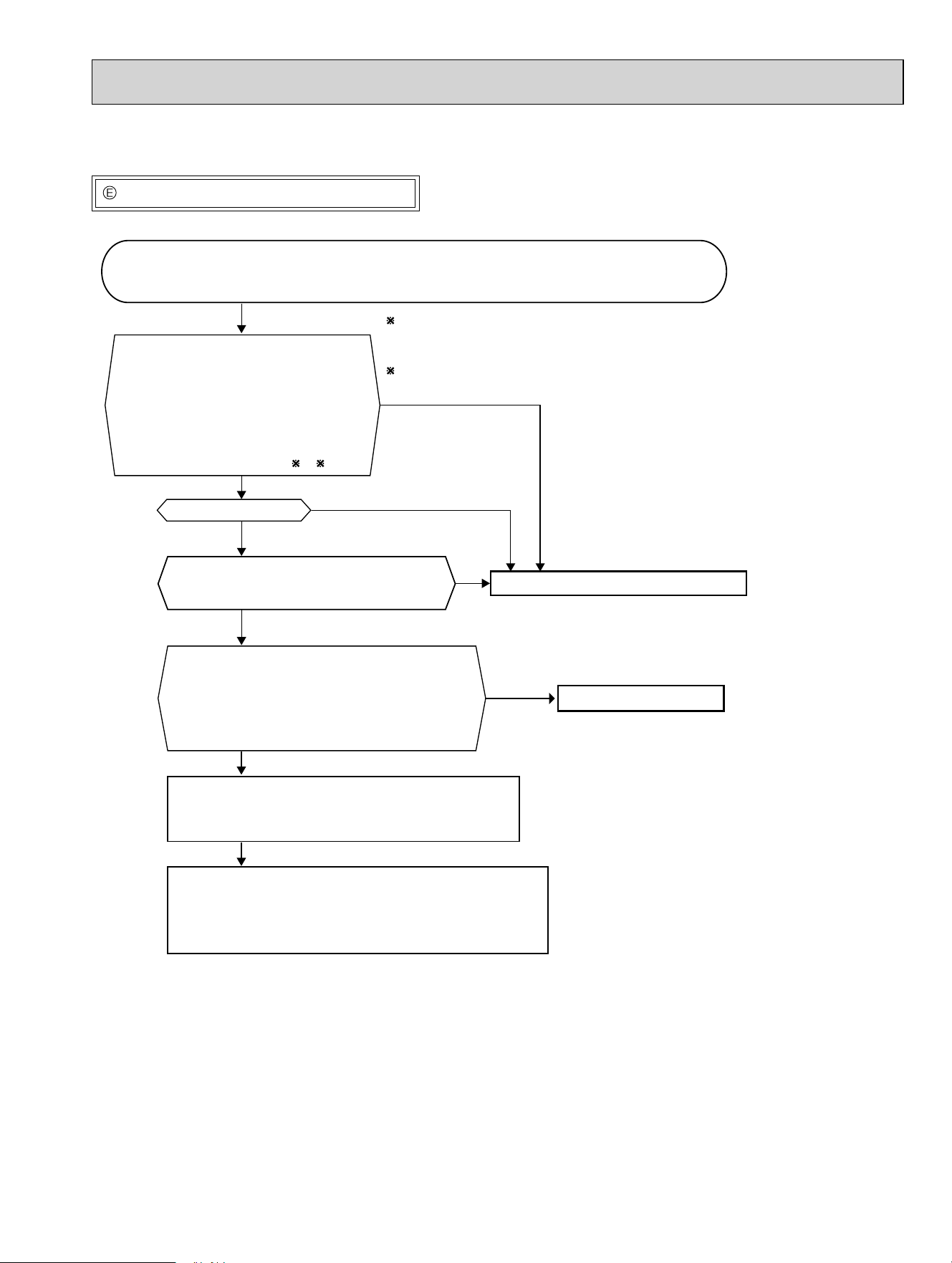
77
How to check inverter/compressor
• When heating, room does not get warm.
• When cooling, room does not get cool.
Disconnect the terminal of the compressor or the connector (CNMC) between the compressor
and the outdoor power P.C. board.
3 minutes after the power supply is turned ON,
start EMERGENCY OPERATION.
Is output balanced?
Clarify the causes by counting time until the inverter stops.
0 to 10 seconds: compressor layer short
10 to 60 seconds: compressor lock
60 seconds to 5minutes: refrigerant circuit defective
5 minutes or more: normal
Turn OFF the power supply of indoor and
outdoor unit, and measure the compressor
winding resistance between the compressor
terminals.
Is the resistance between each terminal normal?
(Refer to 11-5.)
Is the input voltage to the outdoor control
P.C. board 370 VDC or more?
Reconnect the lead wire of compressor, and turn ON
the power supply to indoor and outdoor unit.
3 minutes later, start EMERGENCY OPERATION.
Replace the compressor.
Replace the outdoor power P.C. board.
$IWHUWKHRXWGRRUIDQVWDUWVUXQQLQJZDLWIRUPLQXWH
or more before measuring the voltage.
7KHRXWSXWYROWDJHYDOXHVKDYHWKHWROHUDQFHRI
7KHRXWSXWGLIIHUVGHSHQGLQJRQWKHFDSDFLW\RUWKH
number of indoor units to be operated.
Measure the voltage between each
lead wire leading to the compressor.
U (BLK) - V (WHT)
V (WHT) - W (RED)
W (RED) - U (BLK)
Output voltage:
99
Is proper output voltage detected?
No
No
Yes
Yes
Yes
No
Yes
No
OBH702C
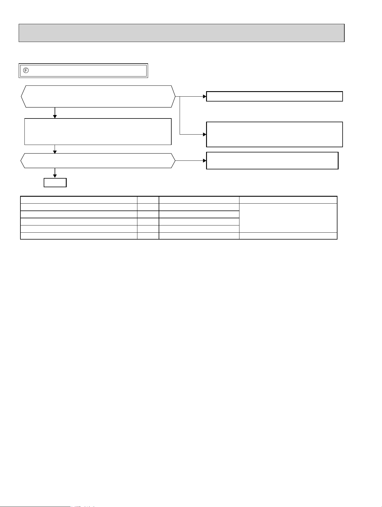
78
Check of outdoor thermistors
• When thermistor is abnormal.
Thermistor
Defrost
Discharge temperature
Outdoor heat exchanger temperature
Ambient temperature
Fin temperature
Symbol
RT61
RT62
RT68
RT65
RT64
Connector, Pin No.
Between CNTH1 pin1 and pin2
Between CNTH1 pin3 and pin4
Between CNTH1 pin7 and pin8
Between CNTH2 pin1 and pin2
Between CN171 pin1 and pin2
Outdoor control P.C. board
Outdoor power P.C. board
Board
Normal
Yes
No
Abnormal
Disconnect the connector in the following table and
measure the resistance of the thermistor to check
whether the thermistor is normal or not. (Refer to 11-7.)
Does the unit operate 10 minutes or more without
showing thermistor abnormality?
Normal
Replace the outdoor control P.C. board or the
outdoor power P.C. board.
Reconnect the connector in the following table and
disconnect the lead wire leading to the compressor.
3 minutes after turning ON the power supply,
start EMERGENCY OPERATION.
(MXZ-3C24/3C30/4C36NA,
MXZ-3C24/3C30/4C36NA2)
Replace the thermistor.
(MXZ-5C42NA,MXZ-5C42NA2,
MXZ-2C20/3C24/3C30NAHZ,
MXZ-2C20/3C24/3C30NAHZ2)
Replace the thermistor except RT64.
If RT64 is abnormal, replace the outdoor power
P.C. board since RT64 is combined with this board.
OBH702C
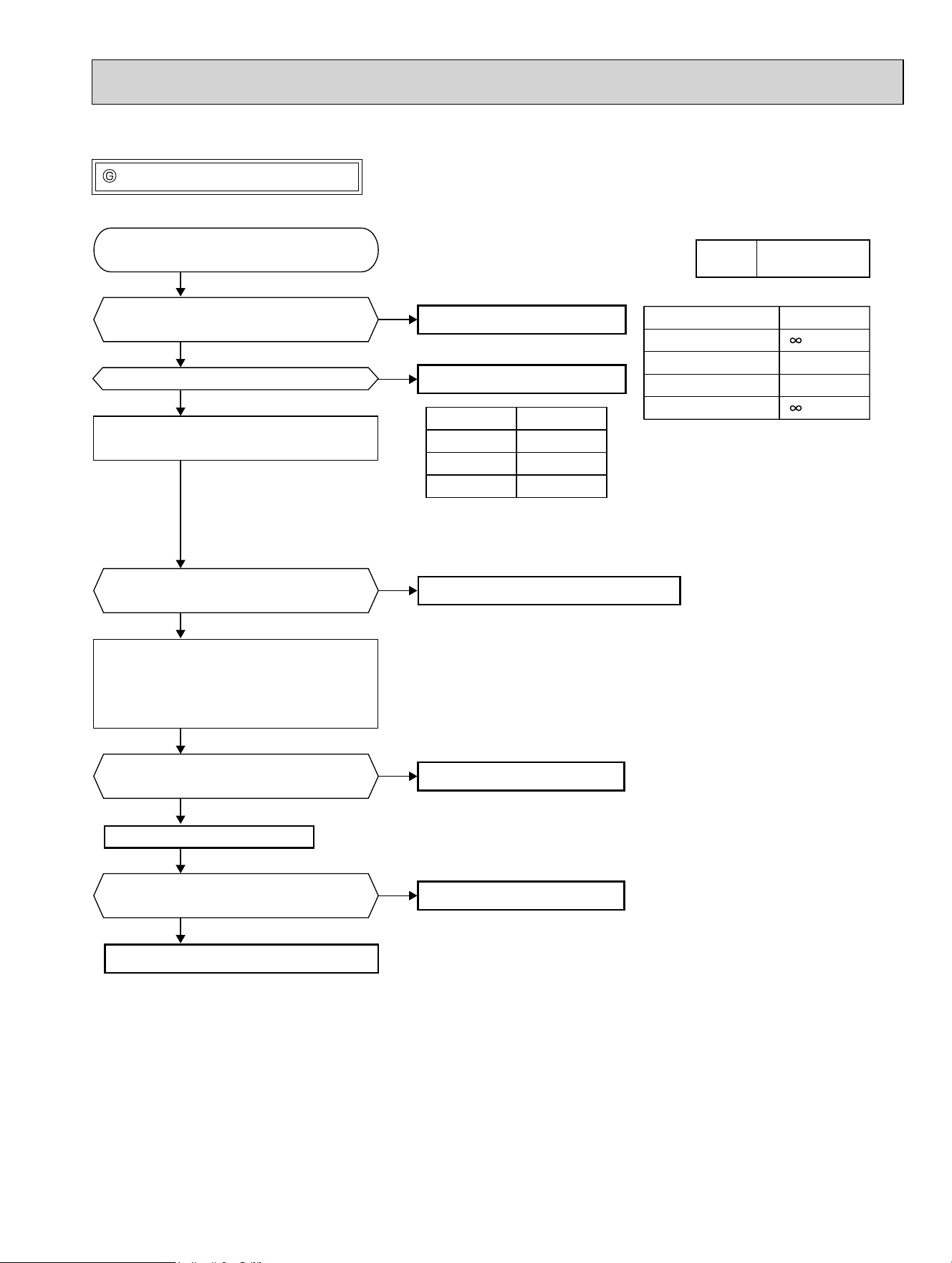
79
No
Yes
No
Yes
No
Yes
No
Yes
No
Yes
Disconnect CNF1 and measure the
resistance of the outdoor fan motor.
Is the resistance of outdoor fan motor
normal? (Refer to right table)
Turn on the power supply to start operation
and measure the voltage of connector CNF1.
Turn OFF the power supply and connect
the connector CNF1.
Turn ON the power supply and measure
the voltage of connector CNF1 while
rotating the motor by the hand.
Does the outdoor fan motor rotate smoothly?
Replace the outdoor fan motor.
Resistance
N
N
Measuring points
* To measure the resistance, connect
the negative (-) end of the tester to pin4.
* To measure the voltage, connect the negative (-)
end of the tester to pin4.
* Voltage between pin4 and 6 should be measured
within 1 minute after the operation starts.
pin1 - pin4
pin5 - pin4
pin6 - pin4
pin7 - pin4
Voltage
15 VDC
294/325 VDC
1 - 5 VDC
CNF1
pin1 - pin4
pin5 - pin4
pin6 - pin4
Is the voltage of connector CNF1
normal? (Refer to right table.)
Does the voltage between pin7 and pin4
of connector CNF1 repeat 0V and 5V?
Replace the outdoor fan motor.
Does the fan motor operate for about
5 seconds?
Replace the outdoor fan motor.
Replace the outdoor fan motor.
Start operation.
Replace the outdoor control P.C. board.
Replace the outdoor control P.C. board.
CNF1
Outdoor control
P.C. board
Check of outdoor fan motor
• Fan motor does not operate or stops operating shortly after starting the operation.
OBH702C
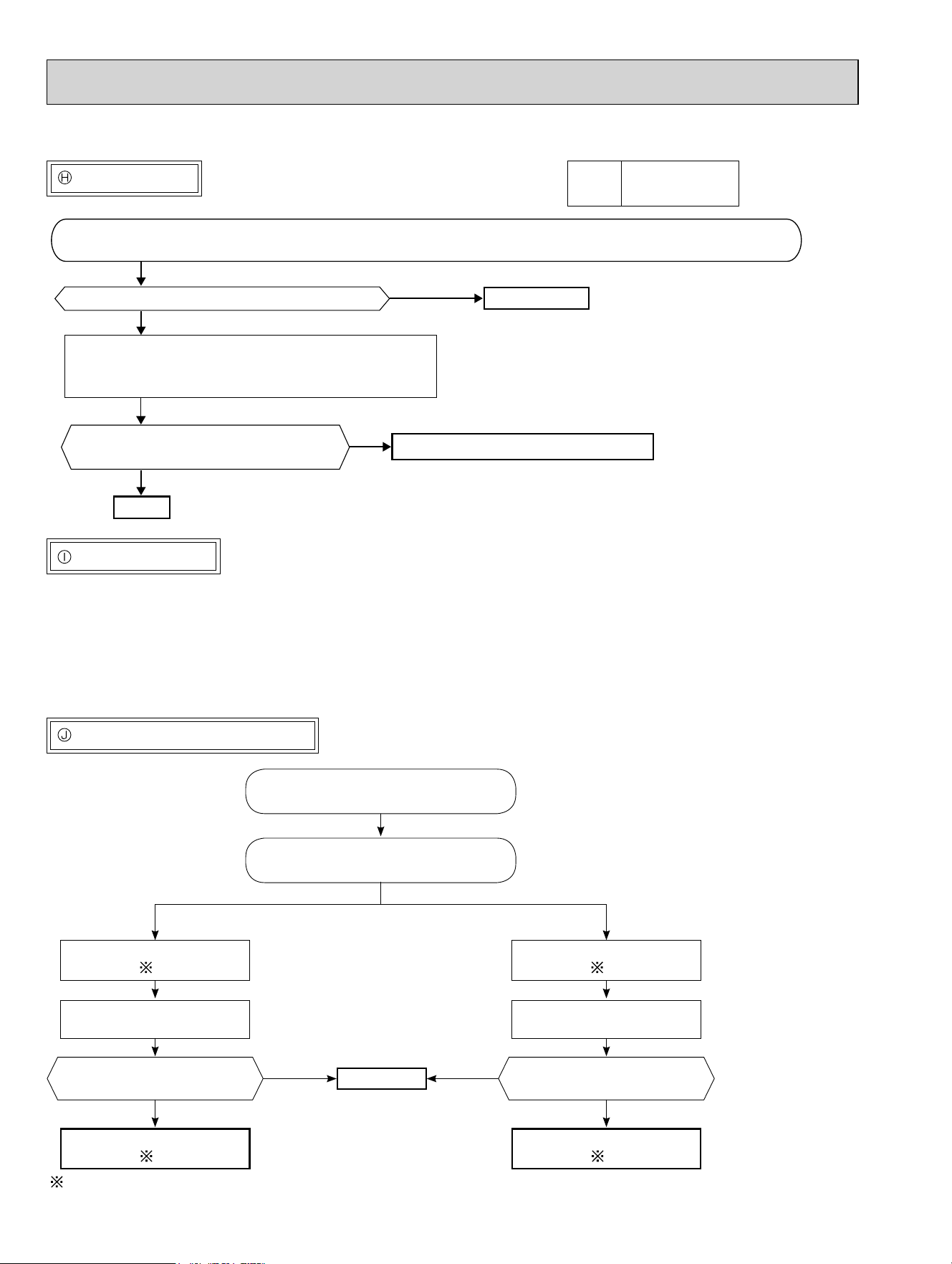
80
The other cases
Indoor unit does not operate. (different operating models in multi system)
• When you try to run 2 indoor units simultaneously, one for cooling and the other for heating, the unit which transmits signal to
the outdoor units fi rst decides the operation mode.
• When the above situation occurs, set all the indoor units to the same mode, turn OFF the indoor units, and then turn them
back ON.
• Though the top of the indoor unit sometimes gets warm, this does not mean malfunction. The reason is that the refrigerant gas
continuously fl ows into the indoor unit even while it is not operating.
• When the operation frequency does not go up from the lowest frequency.
Check of bus-bar voltage
•Check the voltage of power supply.
•Confi rm outdoor unit failure mode
recall function. (Refer to 11-2.2.)
Blink 5 times
Confi rm LED1 indication lamp on the
outdoor control P.C. board.
Replace the outdoor power
P.C. board.
Blink 9 times
Replace the outdoor control
P.C. board.
Turn OFF power supply before removing P.C. board.
Confi rm LED1 indication lamp
on the outdoor control P.C.
board.
Turn ON power supply. Start
operation.
Lighting
Replace the outdoor control
P.C. board.
Blink 9 times
Replace the outdoor power
P.C. board.
Confi rm LED1 indication lamp
on the outdoor control P.C.
board.
Turn ON power supply. Start
operation.
Normal
Lighting Lighting
Check of HPS
Infinity
No
Yes
1. Disconnect the connector CN63H in the outdoor control P.C. board.
2. Check the resistance of HPS after 1 minute has passed since the outdoor unit power supply was turned OFF.
Check the resistance between each terminal.
Reconnect CN63H.
Turn ON the power supply to the indoor and outdoor unit.
3 minutes later, start EMERGENCY OPERATION.
Is HPS protection displayed immediately
after compressor starts?
Replace HPS.
Replace the outdoor control P.C. board.
Normal
CN63H
Outdoor control
P.C. board
OBH702C
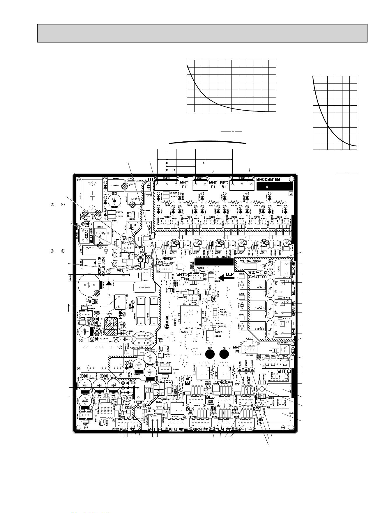
81
11-7. TEST POINT DIAGRAM AND VOLTAGE
1. Outdoor control P.C. board
MXZ-3C24NA MXZ-3C30NA
MXZ-4C36NA
0 102030405060708090100110120
32 50 68 86 104 122 140 158 176 194 212 230 248
700
600
500
400
300
200
100
0
(ºC)
(ºF)
Thermistor R100 = 13.36 k ± 2% , B constant = 4014 ± 2%
Rt = 13.36exp{4014( )} , t: ºC = (ºF - 32)/1.8
5HVLVWDQFHN
Temperature
273+t
1
373
1
Discharge temperature thermistor (RT62)
-20-10 0 10203040
-4 14 32 50 68 86 104
(ºC)
(ºF)
100
90
80
70
60
50
40
30
20
10
0
5HVLVWDQFHN
Temperature
273+t
1
298
1
Thermistor R25 = 10 k ± 2%
B constant = 3950 ± 2%
Rt = 10exp{3950( )}
t : ºC = (ºF - 32)/1.8
Defrost thermistor (RT61)
Ambient temperature thermistor (RT65)
Outdoor heat exchanger temperature
thermistor (RT68)
CN601
230 VAC
Room A
Input
Room B Room C Room D
Defrost thermistor
(RT61)
Discharge temperature
thermistor (RT62)
Outdoor heat exchanger
temperature thermistor
(RT68)
CNTH1
CNTH2
Ambient temperature
thermistor
(RT65)
SW1
LED3
LEV: 12 VDC
pulse wave
LED2
LED1
SW2
SW871
CN712 R.V. coil
208/230 VAC
Output
CN713 Valve coil
208/230 VAC
Output
CN714 Base heater
208/230 VAC
Output
CNAC
to outdoor power P.C.
board 208/230 VAC
Input
F711 FUSE
T3.15AL250V
CN611
Serial signal 12 ~ 24 V
CN621
(
(-)
CN701 Signal
transmission
(To power board)
5 VDC pulse wave
CN702 Signal
transmission
(To power board)
5 VDC pulse wave
(+)
(+)
(-)
(-)
15 V
(-)
15 V
CN63H
High
pressure
switch
CNDC
Bus-bar
voltage
290 ~ 370
VDC
Bus-bar voltage
290 ~ 370 VDC
15 VDC
CNF1
To fan motor
V
FG
(Rotate signal)
(Voltage between
right pins of PC931,
pin 3 and pin 4)
(Same as
&1)í
V
SP
(Rotate instruction)
(Voltage between pins
of C930): 0 V DC
(when stopped),
1.8 - 6.5 V DC
(when operated)
(Correspond to
&1)í
CN741
Signal translation
(
To Communication
adaptor board
)
CN791 LEV Room A
CN792 LEV Room B
CN794 LEV Room D
CN793 LEV Room C
OBH702C
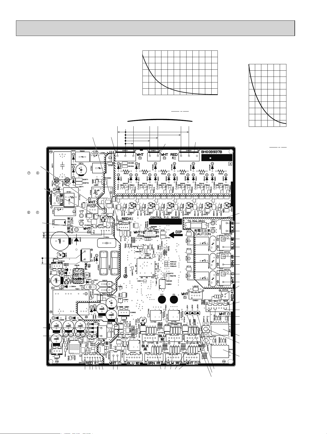
82
MXZ-5C42NA
MXZ-2C20NAHZ MXZ-3C24NAHZ
MXZ-3C30NAHZ
0 102030405060708090100110120
32 50 68 86 104 122 140 158 176 194 212 230 248
700
600
500
400
300
200
100
0
(ºC)
(ºF)
Thermistor R100 = 13.36 k ± 2% , B constant = 4014 ± 2%
Rt = 13.36exp{4014( )} , t: ºC = (ºF - 32)/1.8
5HVLVWDQFHN
Temperature
273+t
1
373
1
Discharge temperature thermistor (RT62)
-20 -10 0 10 20 30 40
-4 14 32 50 68 86 104
(ºC)
(ºF)
100
90
80
70
60
50
40
30
20
10
0
5HVLVWDQFHN
Temperature
273+t
1
298
1
Thermistor R25 = 10 k ± 2%
B constant = 3950 ± 2%
Rt = 10exp{3950( )}
t : ºC = (ºF - 32)/1.8
Defrost thermistor (RT61)
Ambient temperature thermistor (RT65)
Outdoor heat exchanger temperature
thermistor (RT68)
CN601
230 VAC
Room A
Input
Room B Room C Room D Room E
Defrost thermistor
(RT61)
Discharge temperature
thermistor (RT62)
Outdoor heat exchanger
temperature thermistor
(RT68)
CNTH1
CNTH2
Ambient temperature
thermistor
(RT65)
SW1
LED3
LEV: 12 VDC
pulse wave
LED2
LED1
SW2
SW871
CN712 R.V. coil
208/230 VAC
Output
CN713 Valve coil
208/230 VAC
Output
CN714 Base heater
208/230 VAC
Output
CNAC
to outdoor power P.C.
board 208/230 VAC
Input
F711 FUSE
T3.15AL250V
CN611
Serial signal 12 ~ 24 V
CN621
CN791 LEV Room A
(
CN792 LEV Room B
CN794 LEV Room D
CN795 LEV Room E
(-)
CN701 Signal
transmission
(To power board)
5 VDC pulse wave
CN702 Signal
transmission
(To power board)
5 VDC pulse wave
CN793 LEV Room C
(+)
(+)
(-)
(-)
15 V
(-)
18 V
CN63H
High
pressure
switch
CNDC
Bus-bar
voltage
290 ~ 370
VDC
Bus-bar voltage
290 ~ 370 VDC
15 VDC
CNF1
To fan motor
V
FG
(Rotate signal)
(Voltage between
right pins of PC931,
pin 3 and pin 4)
(Same as
&1)í
V
SP
(Rotate instruction)
(Voltage between pins
of C930): 0 V DC
(when stopped),
1.8 - 6.5 V DC
(when operated)
(Correspond to
&1)í
CN741
Signal translation
(
To Communication
adaptor board
)
1. Outdoor control P.C. board
OBH702C
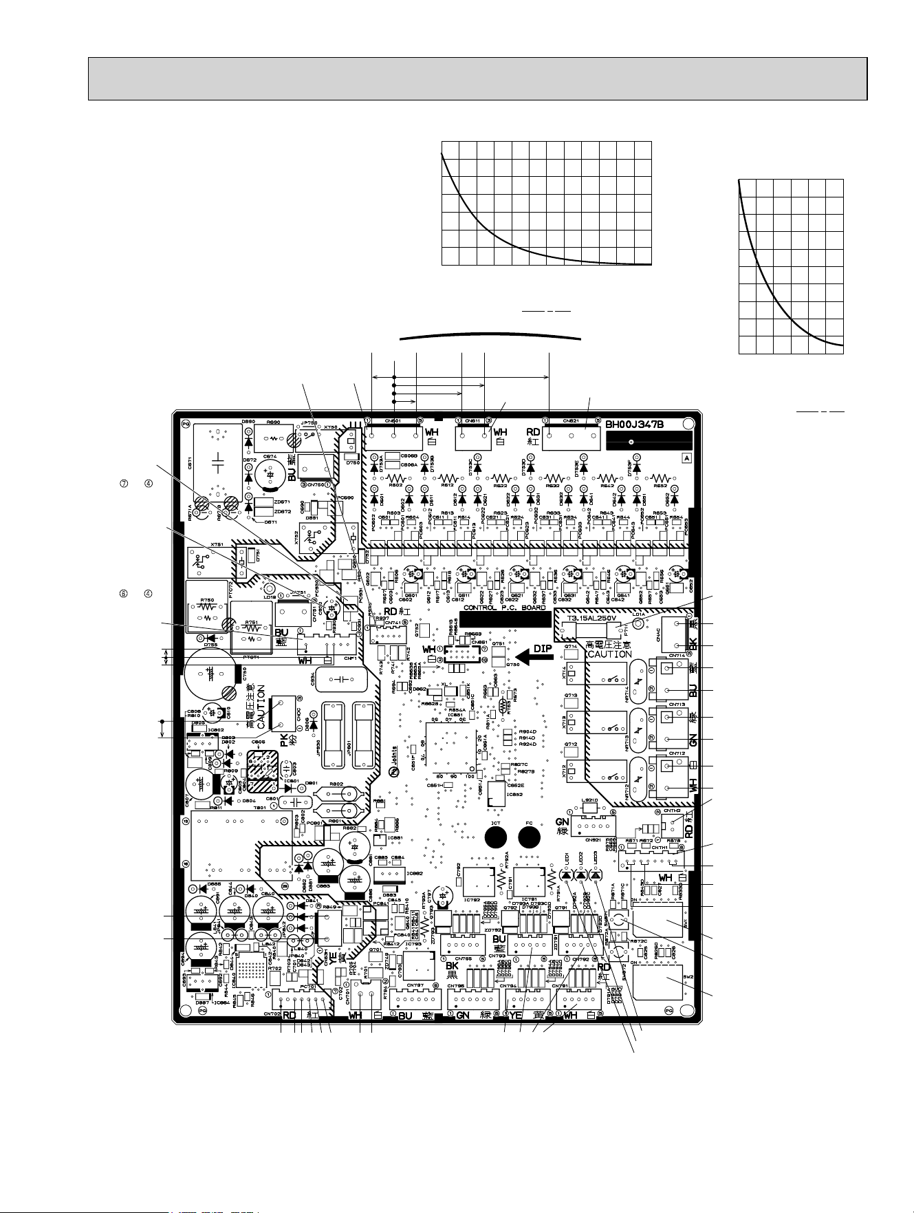
83
MXZ-3C24NA2 MXZ-3C30NA2
MXZ-4C36NA2
0 102030405060708090100110120
32 50 68 86 104 122 140 158 176 194 212 230 248
700
600
500
400
300
200
100
0
(ºC)
(ºF)
Thermistor R100 = 13.36 k ± 2% , B constant = 4014 ± 2%
Rt = 13.36exp{4014( )} , t: ºC = (ºF - 32)/1.8
5HVLVWDQFHN
Temperature
273+t
1
373
1
Discharge temperature thermistor (RT62)
-20-10 0 10203040
-4 14 32 50 68 86 104
(ºC)
(ºF)
100
90
80
70
60
50
40
30
20
10
0
5HVLVWDQFHN
Temperature
273+t
1
298
1
Thermistor R25 = 10 k ± 2%
B constant = 3950 ± 2%
Rt = 10exp{3950( )}
t : ºC = (ºF - 32)/1.8
Defrost thermistor (RT61)
Ambient temperature thermistor (RT65)
Outdoor heat exchanger temperature
thermistor (RT68)
CN601
230 VAC
Room A
Input
Room B Room C Room D
Defrost thermistor
(RT61)
Discharge temperature
thermistor (RT62)
Outdoor heat exchanger
temperature thermistor
(RT68)
CNTH1
CNTH2
Ambient temperature
thermistor
(RT65)
SW1
LED3
LEV: 12 VDC
pulse wave
LED2
LED1
SW2
SW871
CN712 R.V. coil
208/230 VAC
Output
CN713 Valve coil
208/230 VAC
Output
CN714 Base heater
208/230 VAC
Output
CNAC
to outdoor power P.C.
board 208/230 VAC
Input
F711 FUSE
T3.15AL250V
CN611
Serial signal 12 ~ 24 V
CN621
CN791 LEV Room A
(
CN792 LEV Room B
CN794 LEV Room D
(-)
CN701 Signal
transmission
(To power board)
5 VDC pulse wave
CN702 Signal
transmission
(To power board)
5 VDC pulse wave
CN793 LEV Room C
(+)
(+)
(-)
(-)
15 V
(-)
15 V
CN63H
High
pressure
switch
CNDC
Bus-bar
voltage
290 ~ 370
VDC
Bus-bar voltage
290 ~ 370 VDC
15 VDC
CNF1
To fan motor
V
FG
(Rotate signal)
(Voltage between
right pins of PC931,
pin 3 and pin 4)
(Same as
&1)í
V
SP
(Rotate instruction)
(Voltage between pins
of C930): 0 V DC
(when stopped),
1.8 - 6.5 V DC
(when operated)
(Correspond to
&1)í
CN741
Signal translation
(
To Communication
adaptor board
)
1. Outdoor control P.C. board
OBH702C
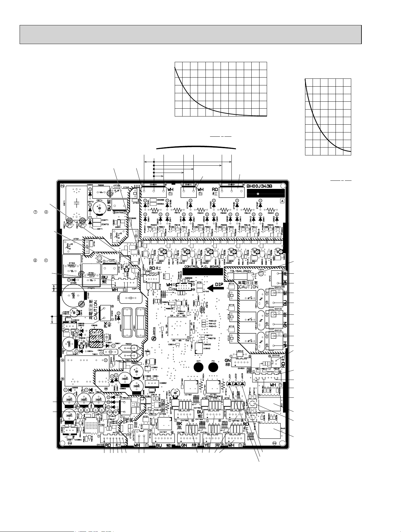
84
MXZ-5C42NA2
MXZ-2C20NAHZ2 MXZ-3C24NAHZ2
MXZ-3C30NAHZ2
0 102030405060708090100110120
32 50 68 86 104 122 140 158 176 194 212 230 248
700
600
500
400
300
200
100
0
(ºC)
(ºF)
Thermistor R100 = 13.36 k ± 2% , B constant = 4014 ± 2%
Rt = 13.36exp{4014( )} , t: ºC = (ºF - 32)/1.8
5HVLVWDQFHN
Temperature
273+t
1
373
1
Discharge temperature thermistor (RT62)
-20 -10 0 10 20 30 40
-4 14 32 50 68 86 104
(ºC)
(ºF)
100
90
80
70
60
50
40
30
20
10
0
5HVLVWDQFHN
Temperature
273+t
1
298
1
Thermistor R25 = 10 k ± 2%
B constant = 3950 ± 2%
Rt = 10exp{3950( )}
t : ºC = (ºF - 32)/1.8
Defrost thermistor (RT61)
Ambient temperature thermistor (RT65)
Outdoor heat exchanger temperature
thermistor (RT68)
CN601
230 VAC
Room A
Input
Room B Room C Room D Room E
Defrost thermistor
(RT61)
Discharge temperature
thermistor (RT62)
Outdoor heat exchanger
temperature thermistor
(RT68)
CNTH1
CNTH2
Ambient temperature
thermistor
(RT65)
SW1
LED3
LEV: 12 VDC
pulse wave
LED2
LED1
SW2
SW871
CN712 R.V. coil
208/230 VAC
Output
CN713 Valve coil
208/230 VAC
Output
CN714 Base heater
208/230 VAC
Output
CNAC
to outdoor power P.C.
board 208/230 VAC
Input
F711 FUSE
T3.15AL250V
CN611
Serial signal 12 ~ 24 V
CN621
CN791 LEV Room A
(
CN792 LEV Room B
CN794 LEV Room D
CN795 LEV Room E
(-)
CN701 Signal
transmission
(To power board)
5 VDC pulse wave
CN702 Signal
transmission
(To power board)
5 VDC pulse wave
CN793 LEV Room C
(+)
(+)
(-)
(-)
15 V
(-)
18 V
CN63H
High
pressure
switch
CNDC
Bus-bar
voltage
290 ~ 370
VDC
Bus-bar voltage
290 ~ 370 VDC
15 VDC
CNF1
To fan motor
V
FG
(Rotate signal)
(Voltage between
right pins of PC931,
pin 3 and pin 4)
(Same as
&1)í
V
SP
(Rotate instruction)
(Voltage between pins
of C930): 0 V DC
(when stopped),
1.8 - 6.5 V DC
(when operated)
(Correspond to
&1)í
CN741
Signal translation
(
To Communication
adaptor board
)
1. Outdoor control P.C. board
OBH702C
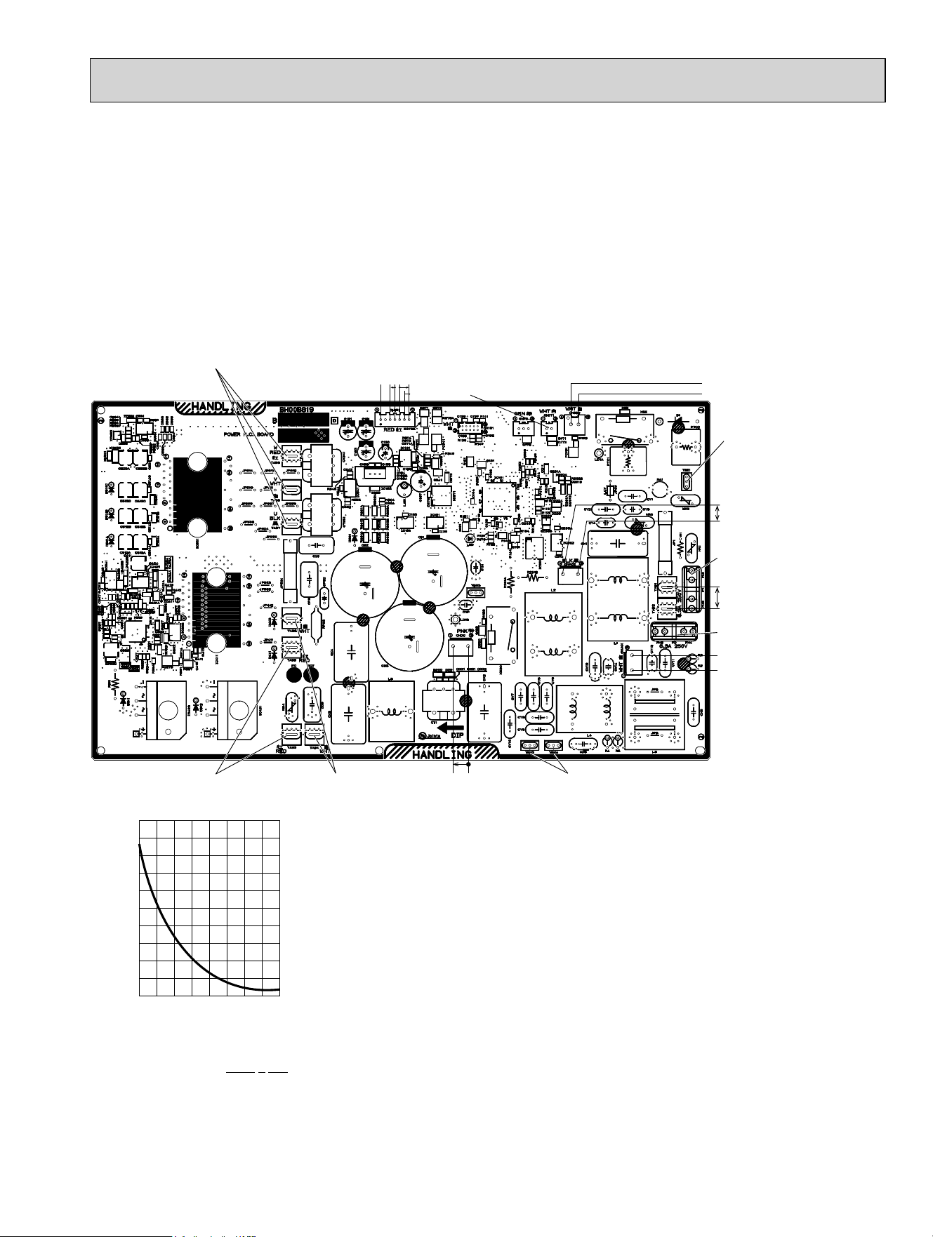
85
MXZ-3C24NA MXZ-3C30NA MXZ-4C36NA
MXZ-3C24NA2 MXZ-3C30NA2 MXZ-4C36NA2
2. Outdoor power P.C. board
Output to drive compressor
Connect to earth
Connect to reactor
(Red line)
Connect to reactor
(White line)
CNDC
Bus-bar voltage
290 - 370 VDC
CNAC1
208/230 V Output
F2 FUSE
T6.3AL250V
F1 FUSE
T6.3AL250V
208/230 VAC
Input
CNAC2
208/230 VAC
Output
Connect to earth
CN152
Signal Transmission
(From Outdoor
Control P.C. board)
5 VDC pulse wave
(
-
)
(+)
CN171
Fin temperature thermistor
(RT64)
CN151 Signal transmission
(To Outdoor control
P.C. board)
5 VDC pulse wave
(+)
(-)
(-)
15 V
15 V
200
180
160
140
120
100
80
60
40
20
0
5HVLVWDQFHN
Temperature
)
&
Fin temperature thermistor (RT64)
Thermistor R50 = 17 k ± 2%
B constant = 4150 ± 3%
5W H[S^`
t : ºC = (º)
273+t
1
323
1
32 50 68 86 104 122 140 158 176
01020304050607080
OBH702C
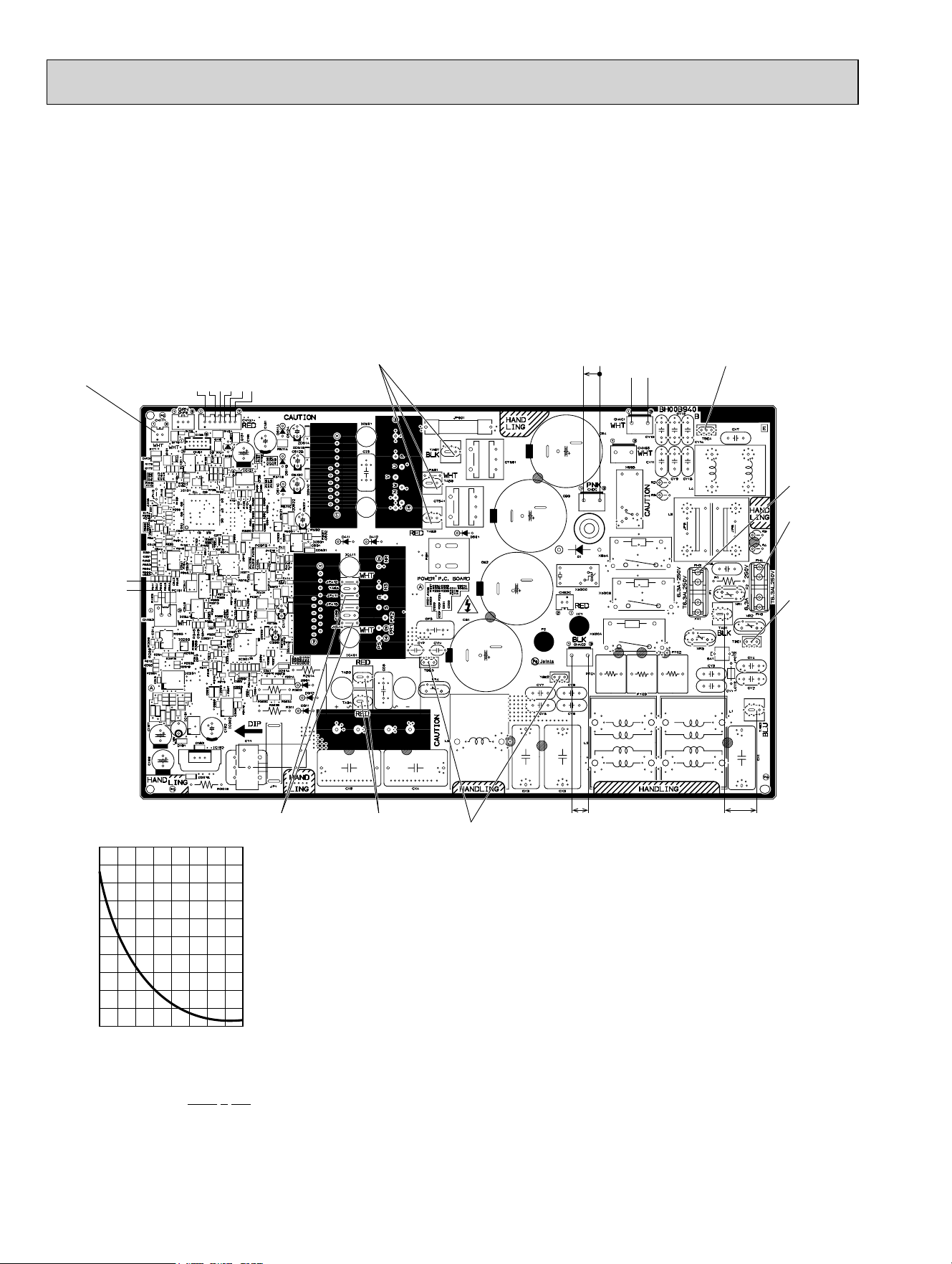
86
MXZ-5C42NA MXZ-2C20NAHZ MXZ-3C24NAHZ MXZ-3C30NAHZ
MXZ-5C42NA2 MXZ-2C20NAHZ2 MXZ-3C24NAHZ2 MXZ-3C30NAHZ2
2. Outdoor power P.C. board
CN152
Signal
Transmission
(
From Outdoor
Control P.C. board
)
5 VDC pulse wave
Output to drive compressor
CNDC
Bus-bar voltage
290 - 370 VDC
CN171
Fin temperature thermistor
(RT64)
208/230 VAC InputCNAC2
208/230
VAC Output
CNAC1
208/230 V Output
Connect to earth
Connect
to earth
Connect
to earth
Connect to reactor
(Red line)
F2 FUSE
T6.3AL250V
F1 FUSE
T6.3AL250V
Connect to reactor
(White line)
(
-
)
(+)
CN151 Signal transmission
(To Outdoor control
P.C. board)
5 VDC pulse wave
(+)
(-)
(-)
15 V
15 V
18 V
200
180
160
140
120
100
80
60
40
20
0
5HVLVWDQFHN
Temperature
)
&
Fin temperature thermistor (RT64)
Thermistor R50 = 17 k ± 2%
B constant = 4150 ± 3%
5W H[S^`
t : ºC = (º)
273+t
1
323
1
32 50 68 86 104 122 140 158 176
01020304050607080
OBH702C
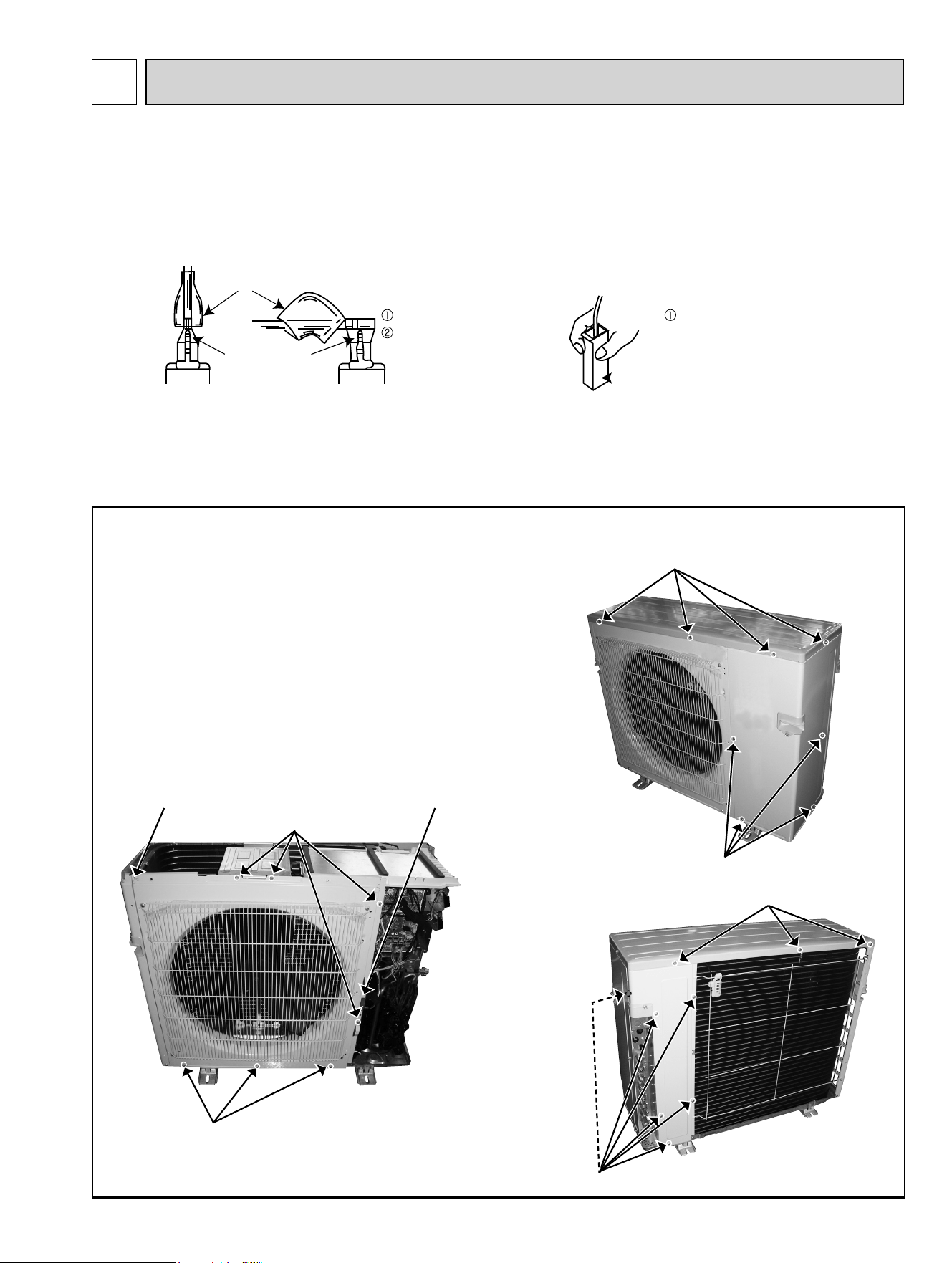
OPERATING PROCEDURE PHOTOS
1. Removing the panels
(1) Remove the screws fixing the top panel, and remove the
top panel.
(2) Remove the screws fixing the service panel.
(3) Pull down the service panel, and remove the service
panel.
(4) Disconnect the power supply and indoor/outdoor connect-
ing wire.
(5) Remove the screws fixing the front panel, and remove the
front panel.
(6) Remove the screws fixing the back panel, and remove
the back panel.
87
12-1. MXZ-3C24NA MXZ-3C30NA MXZ-4C36NA
MXZ-3C24NA2 MXZ-3C30NA2 MXZ-4C36NA2
Photos: MXZ-4C36NA
MXZ-4C36NA2
NOTE: Turn OFF the power supply before disassembly.
Photo 1
Photo 3
Screws of the service panel
Screws of the front panel
Catch of the front panelCatch of the front panel
Screws of the top panel
Screws of the front panel
Screws of the top panel
Screws of the back panel
Photo 2
DISASSEMBLY INSTRUCTIONS
12
(1) Slide the sleeve and check if there is a locking lever or not. (2) The terminal with this connector has the
locking mechanism.
Slide the sleeve.
Pull the terminal while
pushing the locking
lever.
Hold the sleeve, and
pull out the terminal
slowly.
The terminal which has the locking mechanism can be detached as shown below.
There are 2 types ( Refer to (1) and (2)) of the terminal with locking mechanism.
The terminal without locking mechanism can be detached by pulling it out.
Check the shape of the terminal before detaching.
<"Terminal with locking mechanism" Detaching points>
Connector
Sleeve
Locking lever
OBH702C
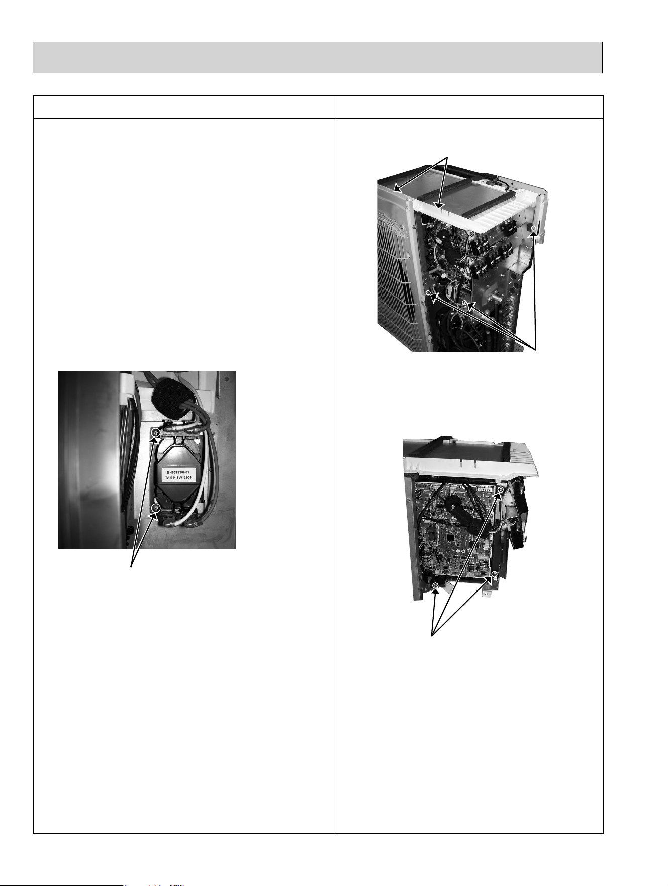
OPERATING PROCEDURE PHOTOS
2. Removing the outdoor control P.C. board, the reac-
tor and the outdoor power P.C. board
(1) Remove the top panel and the service panel (Refer to 1).
(2) Disconnect the power supply and indoor/outdoor connect-
ing wire.
(3) Disconnect the connectors on the outdoor control P.C.
board.
(4) Remove the screws fixing the outdoor control P.C. board
holder, and remove the outdoor control P.C. board.
(5) Disconnect the lead wire from the reactor.
(6) Remove the screws fixing the reactor, and remove the
reactor.
(7) Disconnect the lead wire of the power P.C. board.
(8) Disconnect the catches of the PB cover, and remove the
PB cover.
(9) Remove the outdoor power P.C. board.
88
Photo 4
Catches of the PB cover
Photo 5
Screws of the outdoor control P.C. board holder
Screws of the reactor
Photo 6
Screws
of the
electrical
parts
OBH702C
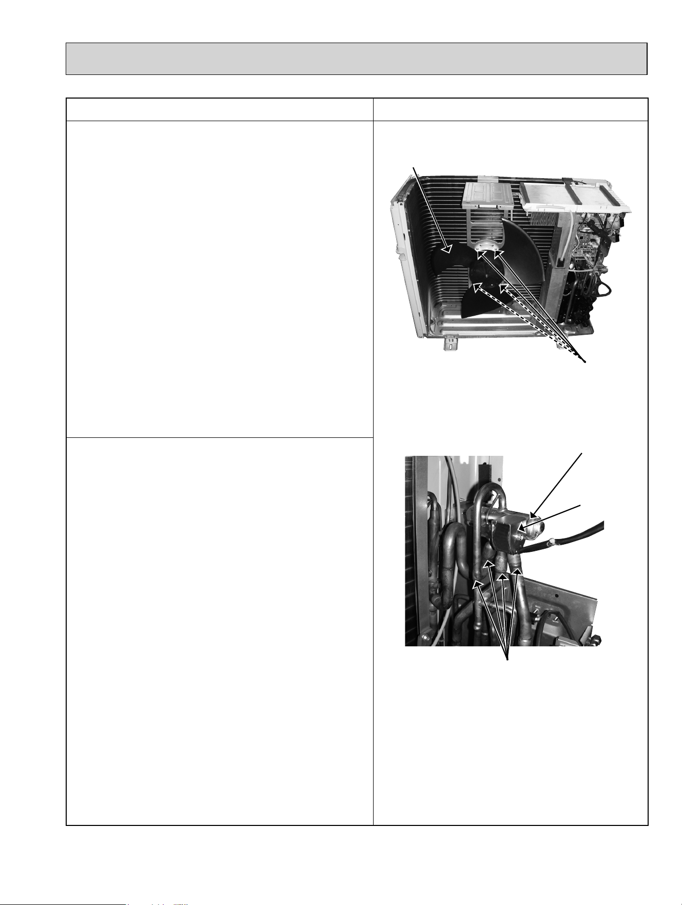
OPERATING PROCEDURE PHOTOS
3. Removing the fan motor
(1) Remove the top panel, the service panel, and the front
panel (Refer to 1).
(2) Disconnect the power supply and indoor/outdoor connect-
ing wire.
(3) Disconnect the connector CNF1 on the outdoor control P.C.
board.
(4) Remove the propeller fan.
(5) Remove the fan motor.
NOTE: The propeller fan nut is a revers thread.
4. Removing the compressor and 4-way valve
(1) Remove the top panel, the service panel, and the front
panel (Refer to 1).
(2) Disconnect the power supply and indoor/outdoor connect-
ing wire, and remove the back panel.
(3) Recover gas from the refrigerant circuit.
NOTE: Recover gas from the pipes until the pressure
gauge shows 0 PSIG.
(4) Disconnect the compressor lead wire from the terminal of
the compressor (U, V, W).
(5) Disconnect the outdoor control P.C. board connectors:
CNF1, CNTH1, CNTH2, CN63H, CN712, CN791, CN792,
CN793, CN794 (MXZ-4C)
(6) Remove the screws fixing the electrical parts, and remove
the electrical parts (Photo 4).
(7) Remove the propeller fan.
(8) Remove the screws fixing the separator, and remove the
separator.
(9) Remove the sound proof felt.
(
10
) Detach the brazed parts of the compressor suction and
discharge pipes (Photo 9).
(
11
)
Remove the compressor nuts and remove the compressor
(Photo 9).
(
12
) Detach the brazed parts of 4-way valve and pipes.
89
4-way valve
R.V. coil
Brazed parts
Photo 8
Photo 7
Propeller fan
Screws of the outdoor fan motor
OBH702C
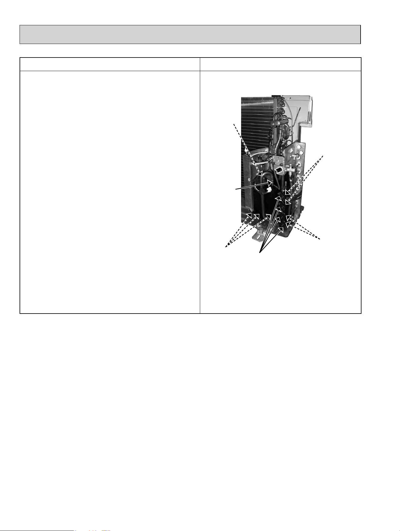
OPERATING PROCEDURE PHOTOS
5. Removing the expansion valve
(1) Remove the top panel, and the service panel (Refer to 1).
(2) Disconnect the power supply and indoor/outdoor connect-
ing wire.
(Gas recovery is not required if the unit is pumped down.)
(3) Remove the LEV coils.
(4) Detach the brazed parts of the expansion valves and
pipes.
90
Photo 9
Suction pipe
brazed part
Compressor nuts
LEV coils
Expansion
valves
Expansion
valves
Discharge pipe
brazed part
OBH702C
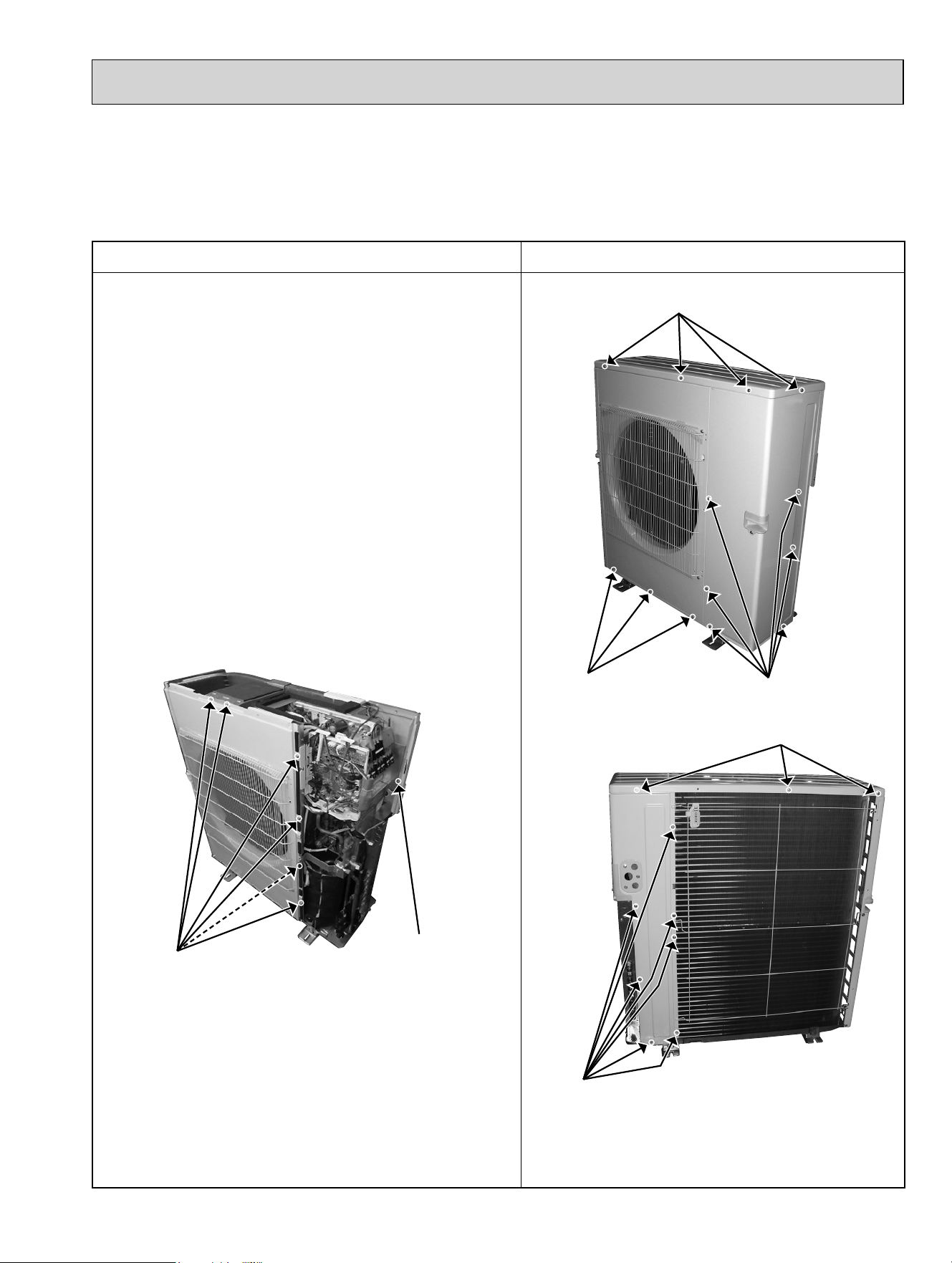
12-2. MXZ-5C42NA MXZ-2C20NAHZ MXZ-3C24NAHZ MXZ-3C30NAHZ
MXZ-5C42NA2 MXZ-2C20NAHZ2 MXZ-3C24NAHZ2 MXZ-3C30NAHZ2
Photos: MXZ-3C30NAHZ
MXZ-3C30NAHZ2
NOTE: Turn OFF the power supply before disassembly.
OPERATING PROCEDURE PHOTOS
1. Removing the panels
(1) Remove the screws fixing the top panel, and remove the
top panel.
(2) Remove the screws fixing the service panel.
(3) Pull down the service panel, and remove the service
panel.
(4) Disconnect the power supply and indoor/outdoor connect-
ing wire.
(5) Remove the screws fixing the front panel, and remove the
front panel.
(6) Remove the screws fixing the back panel, and remove
the back panel.
91
Photo 1
Screws of the service panel
Screws of the front panel
Screws of the top panel
Screws of the top panel
Screws of the back panel
Photo 2
Photo 3
Screws of the front panel
Screw of the back panel
OBH702C
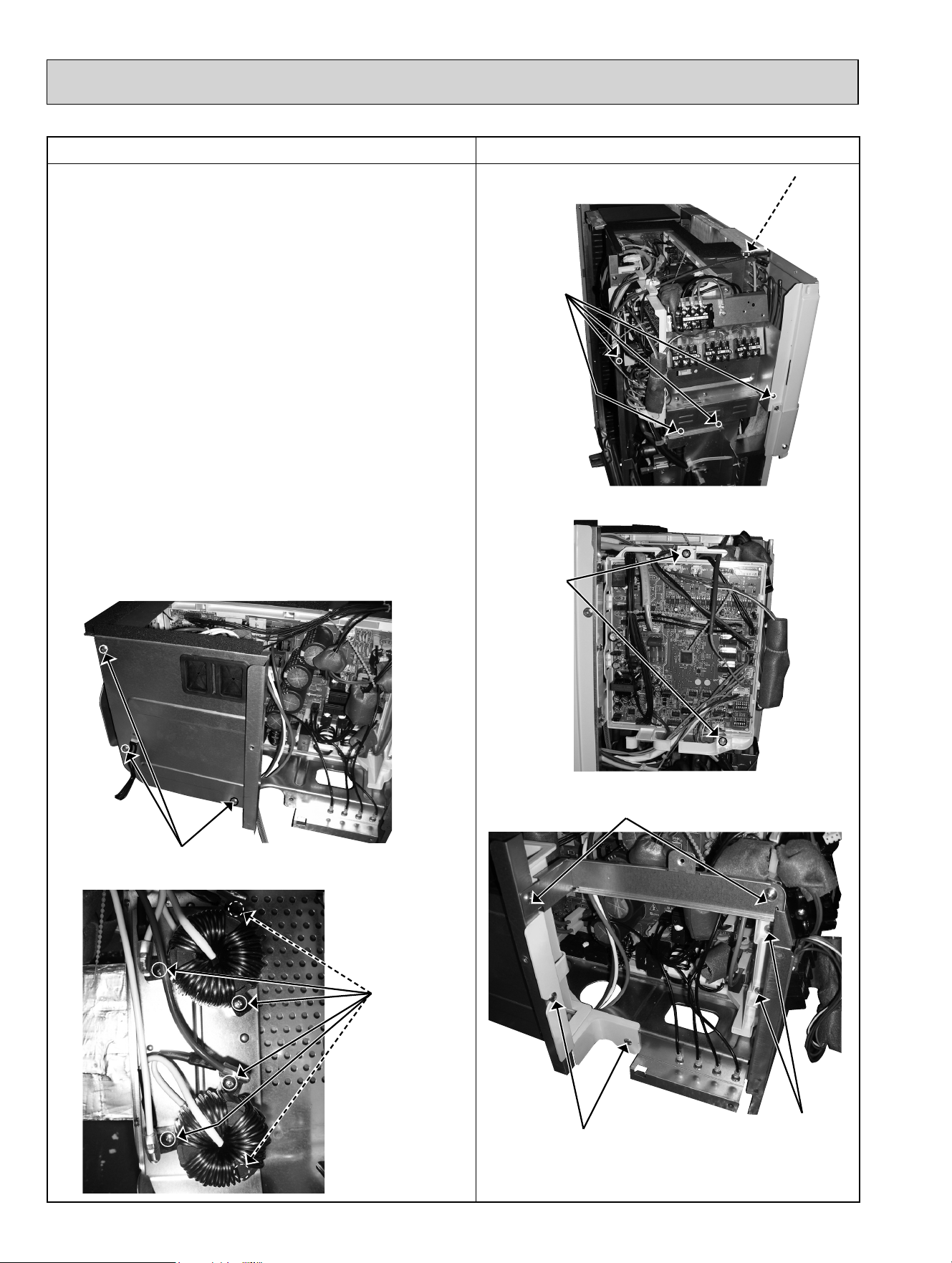
OPERATING PROCEDURE PHOTOS
2. Removing the outdoor control P.C. board, the reac-
tor and the outdoor power P.C. board
(1) Remove the top panel, the service panel and the front
panel (Refer to 1).
(2) Disconnect the power supply and indoor/outdoor connect-
ing wire.
(3)
Disconnect the connectors on the outdoor control P.C. board.
(4) Remove the screws fixing the outdoor control P.C. board,
and remove the outdoor control P.C. board.
(5) Remove the screws fixing the electrical parts, and remove
the electrical parts.
(6)
Remove the screws fixing the TB support, and remove the
TB support.
(7) Remove the screws fixing the control box separator, and
remove the control box separator.
(8) Disconnect the lead wire of the outdoor power P.C. board.
(9) Remove the screws fixing the outdoor power P.C. board,
and remove the outdoor power P.C. board with the out-
door P.C. board holder.
(
10
) Remove the screws fixing the control box F, and remove
the control box F.
(
11
) Remove the screws fixing the reactors, and remove the
reactors.
92
Photo 4
Screws
of the
electrical
parts
Photo 5
Screws
of the
outdoor
control
P.C.
board
Photo 6
Screws of the
outdoor power
P.C. board
Screws of the control box separator
Screws of the TB support
Screws of the control box F
Photo 7
Photo 8
Screws of
the reactor
Screw
of the
electrical
parts
OBH702C
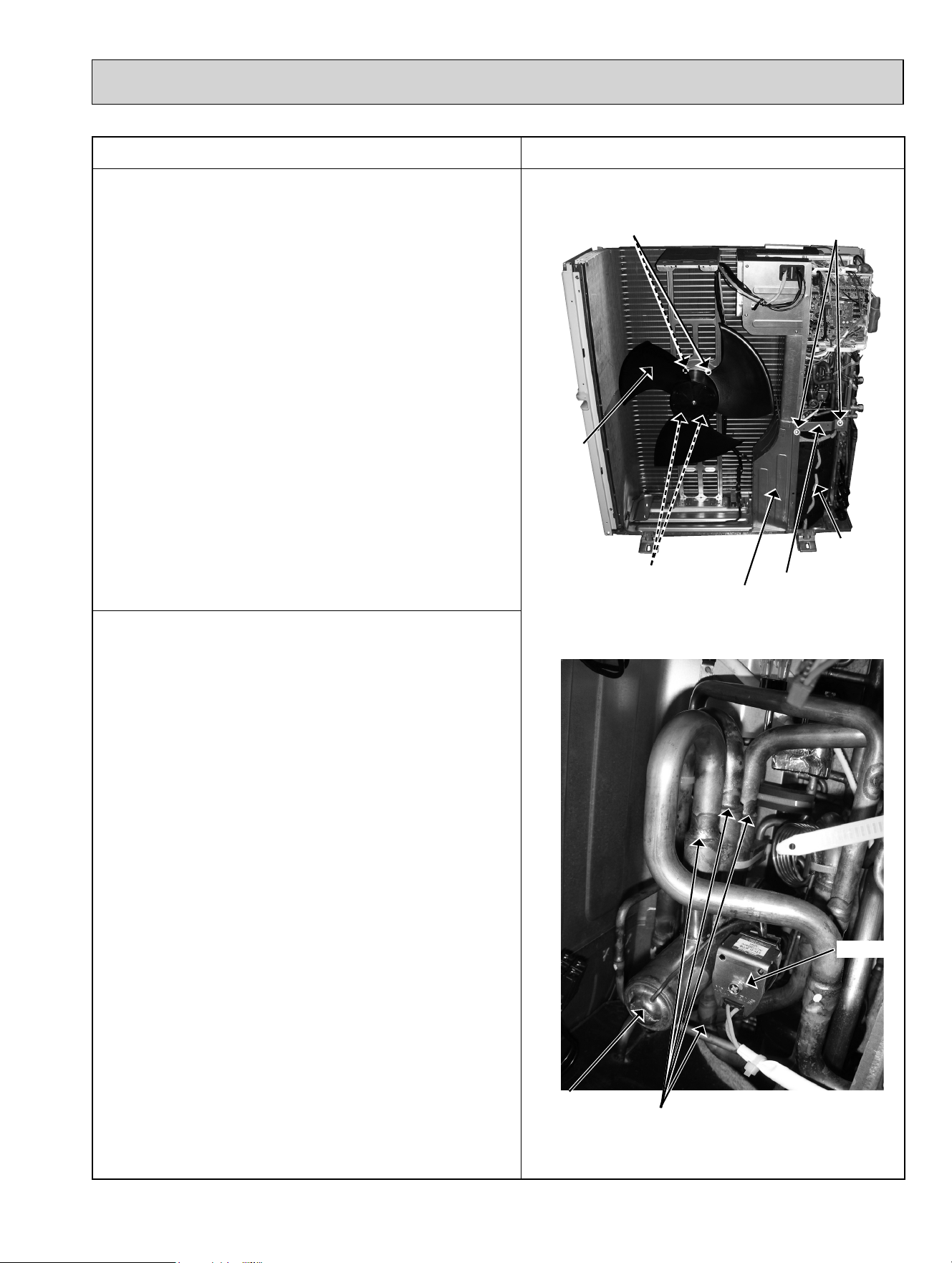
OPERATING PROCEDURE PHOTOS
3. Removing the fan motor
(1) Remove the top panel, the service panel, and the front
panel (Refer to 1).
(2) Disconnect the power supply and indoor/outdoor connect-
ing wire.
(3) Disconnect the connector CNF1 on the outdoor control P.C.
board.
(4) Remove the propeller fan.
(5) Remove the fan motor.
NOTE: The propeller fan nut is a revers thread.
4. Removing the compressor and 4-way valve
(1) Remove the top panel, the service panel and the front
panel.
(2) Disconnect the power supply and indoor/outdoor connect-
ing wire, and remove the back panel.
(3) Recover gas from the refrigerant circuit.
NOTE: Recover gas from the pipes until the pressure
gauge shows 0 PSIG.
(5) Disconnect the compressor lead wire from the terminal of
the compressor (U, V, W).
(6) Disconnect the outdoor control P.C. board connectors:
CNF1, CNTH1, CNTH2, CN63H, CN712, CN713, CN714
(MXZ-C·NAHZ, MXZ-C·NAHZ2), CN791, CN792, CN793
(MXZ-5C42NA, MXZ-3C24/30NAHZ, , MXZ-5C42NA2
MXZ-3C24/30NAHZ2), CN794 (MXZ-5C42NA, MXZ-
5C42NA2), CN795 (MXZ-5C42NA, MXZ-5C42NA2)
(7) Remove the screws fixing the electrical parts, and remove
the electrical parts (Photo 4).
(8) Remove the propeller fan.
(9) Remove the screws fixing the VB fixture, and remove the
VB fixture.
(
10
) Remove the screws fixing the separator, and remove the
separator.
NOTE: When installing the separator, insert the tabs of the
heat exchanger into the separator.
(
11
) Remove the sound proof felt.
(
12
) Detach the brazed parts of the suction and discharge
pipes (Photo 11).
(
13
) Remove the nuts of the compressor, and remove the
compressor (Photo 11).
(
14
)
Detach the brazed parts of 4-way valve and pipes.
93
4-way valve
R.V. coil
Brazed parts
Photo 10
Photo 9
Propeller
fan
Separator
Sound
proof felt
Screws of the outdoor fan motor
Screws of the outdoor fan motor
Screw of the
VB fixture
VB fixture
OBH702C
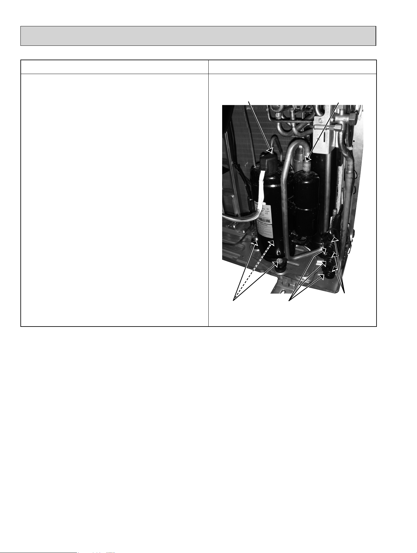
OPERATING PROCEDURE PHOTOS
5. Removing the expansion valve
(1) Remove the top panel, and the service panel (Refer to 1).
(2) Disconnect the power supply and indoor/outdoor connect-
ing wire.
(Gas recovery is not required if the unit is pumped down.)
(3) Remove the LEV coils.
(4) Detach the brazed parts of expansion valves and pipes.
94
Photo 11
Suction pipe
brazed part
Compressor nuts
LEV coils
Expansion
valves
Discharge pipe
brazed part
OBH702C

95
OBH702C

HEAD OFFICE: TOKYO BLDG., 2-7-3, MARUNOUCHI, CHIYODA-KU, TOKYO 100-8310, JAPAN
© Copyright 2014 MITSUBISHI ELECTRIC CORPORATION
Distributed in Mar. 2016. No. OBH702 REVISED EDITION-C
Distributed in Feb. 2016. No. OBH702 REVISED EDITION-B
Distributed in Oct. 2014. No. OBH702 REVISED EDITION-A
Distributed in Sep. 2014. No. OBH702
Made in Japan
New publication, effective Mar. 2016
Specifications are subject to change without notice.