1-1. THE FOLLOWING SHOULD ALWAYS BE OBSERVED FOR SAFETY
• Be sure to read these safety precautions and instructions.
%HVXUHWRREVHUYHWKHZDUQLQJVDQGFDXWLRQVVSHFL¿HGKHUH
• After reading this manual, be sure to store it with the OPERATING INSTRUCTIONS for future reference.
• Please report to your supply authority or obtain their consent before connecting this equipment to the power supply system.
JG79J820H01
ENGLISH
Required Tools for Installation
Phillips screwdriver
Level
Scale
Utility knife or scissors
3 in. (75 mm) hole saw
Torque wrench
Wrench (or spanner)
5/32 in. (4 mm) hexagonal
wrench
Flare tool for R410A
Gauge manifold for R410A
Vacuum pump for R410A
Charge hose for R410A
Pipe cutter with reamer
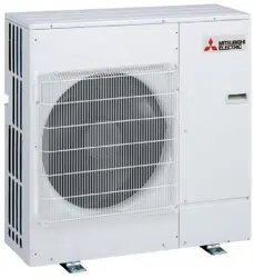
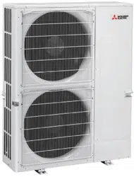
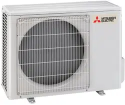
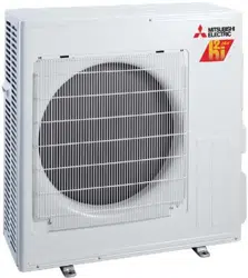
MSZ-FS06/09/12/15/18NA
When installing multi units, refer to the
installation manual of the multi unit for
outdoor unit installation.
■ Do not install the unit by yourself (user).
,PSURSHURULQFRPSOHWHLQVWDOODWLRQFRXOGFDXVH¿UHHOHFWULFVKRFNLQMXU\GXHWR
WKHXQLWIDOOLQJRUZDWHUOHDNDJH&RQVXOWDTXDOL¿HGLQVWDOOHURUWKHGHDOHUIURP
whom you purchased the unit.
■ Follow the instructions detailed in the installation manual.
,QFRPSOHWHLQVWDOODWLRQFRXOGFDXVH¿UHRUHOHFWULFVKRFNLQMXU\GXHWRWKHXQLWIDOO-
ing, or leakage of water.
■ When installing the unit, use appropriate protective equipment and tools for
safety.
Failure to do so could cause injury.
■ Install the unit securely in a place that can bear the weight of the unit.
If the installation location cannot bear the weight of the unit, the unit could fall
causing injury.
■ Do not alter the unit.
,WPD\FDXVH¿UHHOHFWULFVKRFNLQMXU\RUZDWHUOHDNDJH
■ Perform electrical work according to the installation manual and be sure to use
an exclusive circuit. Do not connect other electrical appliances to the circuit.
,IWKHFDSDFLW\RIWKHSRZHUFLUFXLWLVLQVXI¿FLHQWRUWKHUHLVLQFRPSOHWHHOHFWULFDO
ZRUNLWFRXOGUHVXOWLQD¿UHRUDQHOHFWULFVKRFN
■ Ground the unit correctly.
Do not connect the ground wire to a gas pipe, water pipe, lightning rod or
telephone ground. Defective grounding could cause electric shock.
If required, take measures against leakage current.
■ Do not damage the wires.
'DPDJHGZLUHVFRXOGFDXVH¿UH
■ Be sure to shut off the main power when setting up the indoor P.C. board or
wiring.
Failure to do so could cause electric shock.
■ 8VHWKHVSHFL¿HGZLUHVWRVHFXUHO\FRQQHFWWKHLQGRRUDQGRXWGRRUXQLWV$W-
WDFKWKHZLUHV¿UPO\WRDYRLGDSSO\LQJVWUHVVWRWKHWHUPLQDOEORFN
,PSURSHUFRQQHFWLRQFRXOGFDXVH¿UH
■ 'RQRWLQVWDOOWKHXQLWLQDSODFHZKHUHÀDPPDEOHJDVPD\OHDN
If gas leaks and accumulates around the unit, it could cause an explosion.
■ Do not use intermediate connection of the power cord or the extension cord.
Do not connect many devices to one AC outlet.
,WFRXOGFDXVHD¿UHRUDQHOHFWULFVKRFN
■ 8VHWKHSDUWVSURYLGHGRUVSHFL¿HGSDUWVIRUWKHLQVWDOODWLRQZRUN
7KHXVHRIGHIHFWLYHSDUWVFRXOGFDXVHDQLQMXU\RUOHDNDJHRIZDWHUGXHWRD¿UH
an electric shock, the unit falling, etc.
■ When plugging the power supply plug into the outlet, make sure that there is
no dust, blockage, or loose parts both in the outlet and on the plug. Verify that
the power supply plug is completely in the outlet.
If there is dust, blockage, or loose parts on the power supply plug or the outlet, it could
FDXVHHOHFWULFVKRFNRU¿UH,IORRVHSDUWVDUHIRXQGRQWKHSRZHUVXSSO\SOXJUHSODFHLW
■ Securely attach the electrical cover to the indoor unit and the service panel to
the outdoor unit.
If the electrical cover of the indoor unit and/or the service panel of the outdoor unit are
QRWDWWDFKHGVHFXUHO\GXVWZDWHUHWFFRXOGFROOHFWLQWKHXQLWDQGFRXOGFDXVHD¿UHRU
an electric shock.
■ When installing, relocating, or servicing the unit, make sure that no substance
RWKHUWKDQWKHVSHFL¿HGUHIULJHUDQW5$HQWHUVWKHUHIULJHUDQWFLUFXLW
Any presence of foreign substance such as air can cause abnormal pressure rise
and may result in explosion or injury. The use of any refrigerant other than that
VSHFL¿HGIRUWKHV\VWHPZLOOFDXVHPHFKDQLFDOIDLOXUHV\VWHPPDOIXQFWLRQRUXQLW
breakdown. In the worst case, this could lead to a serious impediment to securing
product safety.
■ Do not discharge the refrigerant into the atmosphere. Check that the refriger-
ant gas does not leak after installation has been completed. If refrigerant leaks
during installation, ventilate the room.
,IUHIULJHUDQWFRPHVLQFRQWDFWZLWKD¿UHKDUPIXOJDVFRXOGEHJHQHUDWHG
,IUHIULJHUDQWJDVOHDNVLQGRRUVDQGFRPHVLQWRFRQWDFWZLWKWKHÀDPHRIDIDQ
heater, space heater, stove, etc., harmful gases will be generated.
■ Use appropriate tools and piping materials for installation.
The pressure of R410A is 1.6 times higher than R22. Not using the appropriate
tools and materials, or improper installation could cause the pipes to burst causing
an injury.
■ When pumping down the refrigerant, stop the compressor before disconnecting
the refrigerant pipes.
If the refrigerant pipes are disconnected while the compressor is running and the
stop valve is open, air could be drawn in and the pressure in the refrigeration cycle
could become abnormally high, causing the pipes to burst.
■ When installing the unit, securely connect the refrigerant pipes before starting
the compressor.
If the compressor is started before the refrigerant pipes are connected and the
stop valve is open, air could be drawn in and the pressure in the refrigeration cycle
could become abnormally high, causing the pipes to burst.
■ )DVWHQDÀDUHQXWZLWKDWRUTXHZUHQFKDVVSHFL¿HGLQWKLVPDQXDO
,IIDVWHQHGWRRWLJKWDÀDUHQXWFRXOGEUHDNDQGFDXVHUHIULJHUDQWOHDNDJH
■ Install the unit according to national wiring regulations.
■ When opening or closing the valve below freezing temperatures, refrigerant may
spurt out from the gap between the valve stem and the valve body, resulting in
injuries.
■ Please follow applicable federal, state, or local codes to prevent potential
leakage/electric shock. Or install a ground fault interrupt for the prevention of
leakage and electric shock.
■ Perform the drainage/piping work securely according to the installation manual.
If there is defect in the drainage/piping work, water could drip from the unit, and
damage household items.
■ 'RQRWWRXFKWKHDLULQOHWRUWKHDOXPLQXP¿QVRIWKHRXWGRRUXQLW
This could cause injury.
■ Do not install the outdoor unit where small animals may live.
If small animals enter the unit and damage its electrical parts, it could cause a
PDOIXQFWLRQVPRNHHPLVVLRQRU¿UH.HHSWKHDUHDDURXQGWKHXQLWFOHDQ
CAUTION
(Could lead to serious injury when operated incorrectly.)
WARNING
(Could lead to death or serious injury.)
SPLIT-TYPE AIR CONDITIONERS
INSTALLATION MANUAL
1. BEFORE INSTALLATION
(OHFWULFDOVSHFL¿FDWLRQV
MODEL
MSZ-FS06NA
MSZ-FS09NA
MSZ-FS12NA
MSZ-FS15NA
MSZ-FS18NA
INDOOR UNIT
Power supply (V, PHASE, Hz) 208/230, 1, 60
Min. Circuit Ampacity (A) 1.0
Fan motor (F.L.A.) (A) 0.65
OUTDOOR UNIT
Power supply (V, PHASE, Hz) 208/230, 1, 60
Max. Fuse size (time delay) (A) 15 20
Min. Circuit Ampacity (A) 10 18
Fan motor (F.L.A.) (A) 0.50 0.93
Compressor
(R.L.A) (A) 7.4 13.6
(L.R.A) (A) 9.2 17.0
Control voltage
Indoor unit - Remote controller: (Wireless)
Indoor unit - Outdoor unit: DC12-24 V (Polar)
Pipe
Outside
diameter
Minimum wall
thickness
Insulation
thickness
Insulation
material
inch (mm)
For liquid 1/4 (6.35) 0.0315 (0.8) 5/16 (8)
Heat resistant
foam plastic
6SHFL¿F
gravity
For gas
FS06/09/12 3/8 (9.52) 0.0315 (0.8) 5/16 (8)
FS15/18 1/2 (12.7) 0.0315 (0.8) 5/16 (8)
Limits
Pipe length
MSZ-FS06/09/12NA 65 ft. (20 m) max.
MSZ-FS15/18NA 100 ft. (30 m) max.
Height difference
MSZ-FS06/09/12NA 40 ft. (12 m) max.
MSZ-FS15/18NA 50 ft. (15 m) max.
No. of bends 10 max.
Pipe length
Up to 25 ft. (7.5 m) No additional charge is required.
Exceeding 25 ft. (7.5 m)
Additional charge is required.
(Refer to the table below.)
Refrigerant to be added 1.08 oz each 5 ft. (20 g/m)
1-3. SPECIFICATIONS
1-3-1. POWER SUPPLY AND INDOOR/OUTDOOR
WIRE CONNECTION
• Power should be taken from an exclusive branched circuit.
•
Wiring work should be based on applicable technical standards.
• Wiring connections should be made following the diagram.
• Securely tighten screws.
Connecting wires and the ground wire
• Use solid conductor Min. AWG14 or stranded conductor
Min. AWG14.
• Use double insulated copper wire with 600 V insulation.
• Use copper conductors only.
* Follow local electrical codes.
Power supply cable and ground wire
• Use solid or stranded conductor.
FS06/09/12 Min. AWG14
FS15/18 Min. AWG12
• Use copper conductors only.
* Follow local electrical codes.
Note:
When the indoor unit is powered from the outdoor unit, depend-
ing on local code, a disconnect switch needs to be installed to a
power supply circuit.
• Refrigerant adjustment... If pipe length exceeds 25 ft. (7.5 m),
additional refrigerant (R410A) charge is required.
(The outdoor unit is charged with refrigerant for pipe length up
to 25 ft. [7.5 m])
7KHXQLWKDVÀDUHG FRQQHFWLRQV RQ ERWKLQGRRUDQGRXWGRRU
sides.
• Remove the valve cover from the outdoor unit, then connect
the pipe.
• Refrigerant pipes are used to connect the indoor and outdoor
units.
• Be careful not to crush or over bend the pipe in pipe bending.
1-3-2. REFRIGERANT PIPES
• To prevent condensation, insulate the two refrigerant pipes.
• Refrigerant pipe bending radius must be 4 in. (100 mm) or more.
CAUTION
%HVXUHWRXVHWKHLQVXODWLRQRIVSHFL¿HGWKLFNQHVVWDEOHRQWKH
right). Excessive insulation may cause incorrect installation of
the indoor unit, and too little insulation may cause condensate
to form.
1-2. SELECTING THE INSTALLATION LOCATION
INDOOR UNIT
:KHUHDLUÀRZLVQRWEORFNHG
• Where cool (or warm) air spreads over the entire room.
• On a rigid wall to reduce the possibility of vibration.
• Where it is not exposed to direct sunlight. Do not expose
to direct sunlight also during the period following unpack-
ing to before use.
• Where it can be easily drained.
• At a distance 3 ft. (1 m) or more away from a TV and
radio. Operation of the air conditioner may interfere with
UDGLRRU79UHFHSWLRQ$QDPSOL¿HUPD\EHUHTXLUHGIRU
the affected device.
,QDSODFHDVIDUDZD\DVSRVVLEOHIURPÀXRUHVFHQWDQG
incandescent lights. In order to make the infrared remote
control operate the air conditioner normally. The heat
from the lights may cause deformation or the ultraviolet
may cause deterioration.
•
:KHUHWKHDLU¿OWHUFDQEHUHPRYHGDQGUHSODFHGHDVLO\
• Where it is away from the other heat or steam source.
Note:
Install the indoor unit high on the wall where air can
distribute over the entire room.
REMOTE CONTROLLER
• Where it is convenient to operate and easily visible.
• Where children cannot easily touch it.
6HOHFWDSRVLWLRQDERXWIWPDERYHWKHÀRRU
Check that signals from the remote controller from
that position are received by the indoor unit (‘beep’
or ‘beep beep’ receiving tone sounds). Then, attach
remote controller holder to a pillar or wall and install
wireless remote controller.
Note:
,QURRPVZKHUHLQYHUWHUW\SHÀXRUHVFHQWODPSVDUHXVHG
the signal from the wireless remote controller may not be
received.
OUTDOOR UNIT
• Where it is not overly exposed to strong winds.
:KHUHDLUÀRZLVJRRGDQGGXVWOHVV
• Where neighbours are not annoyed by operation sound
or hot air.
• Where rigid wall or support is available to prevent the
increase of operation sound or vibration.
• Where there is no risk of combustible gas leakage.
• If installing the unit in a location high above the ground,
be sure to secure the unit legs.
• Where it is at least 10 ft. (3 m) away from the antenna
of TV set or radio. Operation of the air conditioner may
interfere with radio or TV reception in areas where recep-
WLRQLVZHDN$QDPSOL¿HUPD\EHUHTXLUHGIRUWKHDIIHFWHG
device.
• Install the unit horizontally.
• Please install it in an area not affected by snowfall or
blowing snow. In areas with heavy snow, please install
DFDQRS\DSHGHVWDODQGRUEDIÀHERDUGV
Note:
• It is advisable to make a piping loop near outdoor unit
so as to reduce vibration.
)RU LQFUHDVHG HI¿FLHQF\ LQVWDOO WKH RXWGRRU XQLW LQ D
location where continuous direct sunlight or excessive
water can be avoided as much as possible.
Note:
When operating the air conditioner in low outside tem-
perature, be sure to follow the instructions described
below.
• Never install the outdoor unit in a place where its air
inlet/outlet side may be exposed directly to wind.
• To prevent exposure to wind, install the outdoor unit
with its air inlet side facing the wall and
DEDIÀHERDUG
on the air outlet side.
Avoid the following places for installation where air
conditioner trouble is liable to occur.
:KHUHÀDPPDEOHJDVFRXOGOHDN
• Where there is an excessive amount of machine oil
in the air.
• :KHUHRLOLVVSODVKHGRUZKHUHWKHDUHDLV¿OOHGZLWK
oily smoke (such as cooking areas and factories, in
which the properties of plastic could be changed and
damaged).
• Salty places such as the seaside.
:KHUH VXO¿GH JDV LV JHQHUDWHG VXFKDV KRW VSULQJ
sewage, waste water.
•
Where there is high-frequency or wireless equipment.
• Where there is emission of high levels of VOCs,
including phthalate compounds, formaldehyde, etc.,
which may cause chemical cracking.
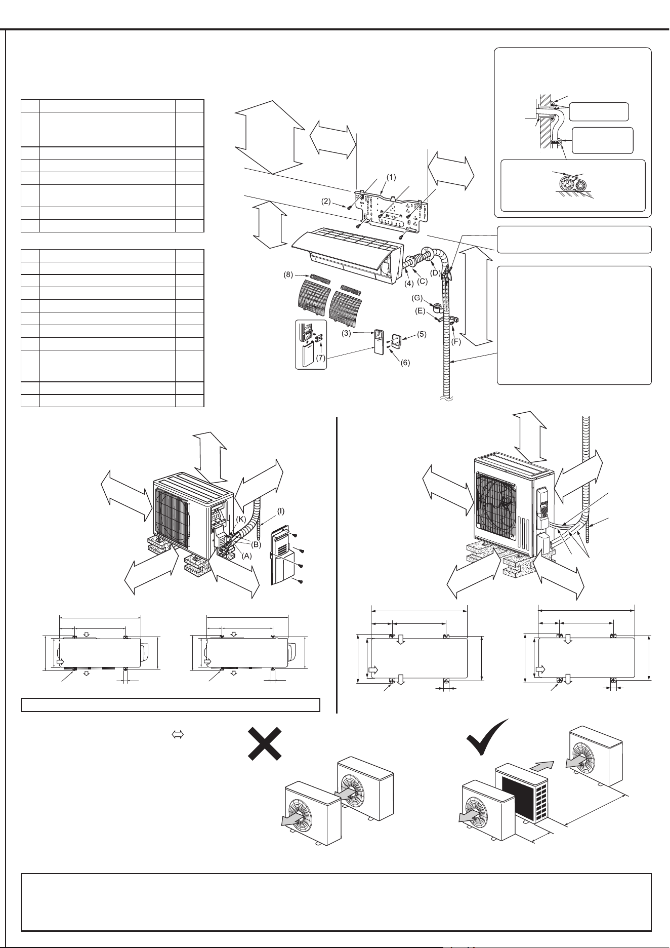
1-4. INSTALLATION DIAGRAM
ACCESSORIES
Check the following parts before installation.
<Indoor unit>
(1) Installation plate 1
(2)
Attachment screws for the installation
plate
4 × 25 mm
5
(3) Wireless remote controller 1
(4) Felt tape (For left or left-rear piping) 1
(5) Remote controller holder 1
(6)
Screws for the remote controller holder
3.5 × 16 mm (Black)
2
(7) Battery (AAA) for (3) 2
(8) $LUFOHDQLQJ¿OWHU 2
FIELD-SUPPLIED PARTS
(A) Indoor/outdoor unit connecting wire*1 1
(B) Extension pipe 1
(C) Wall hole sleeve 1
(D) Wall hole cover 1
(E) Pipe attachment strap 2 to 5
(F) Screw for (E) 4 × 20 mm 2 to 5
(G) Piping tape 1
(H) Putty 1
(I)
Drain hose
(or soft PVC hose, 19/32 in. [15 mm]
inner diameter or hard PVC pipe VP16)
1
(J) Refrigerant oil 1
(K) Power supply cord*1 1
Units should be installed by licensed contractor according to local code requirements.
Indoor unit
Wall hole
sleeve (C)
Cut off the
extra length.
Pipe attachment
strap (E)
Use the wall hole sleeve (C) to prevent
indoor/outdoor connecting wire (A) from
contacting metal parts in the wall and to
protect the wiring from rodents.
Wall hole cover (D)
Seal the wall hole
gap with putty (H).
Attach the pipe
to wall with pipe at-
tachment strap (E).
Attachment screw (F)
4 in. (100 mm)
or more
14 in. (350 mm)
or more
8 in. (200 mm) *3
or more
4 in. (100 mm)
or more
Unit: inch Unit: mm
31-1/2
19-11/16
Air inlet
Air outlet
13-9/16
11-1/4
2-3/8
×
13/16 slot
12~12-3/4
1-9/16
800
500
Air inlet
Air outlet
2-10
×
21 slot
344.5
285
150
40
304~325
5-15/16
<FS06/09/12>
<FS15/18>
(K)
(I)
(B)
(A)
Unit: inch Unit: mm
4 in. (100 mm)
or more
14 in. (350 mm)
or more
20 in. (500 mm) *3
or more
Drain piping for outdoor unit
Install the unit horizontally.
Do not use drain socket in cold regions. Drain may freeze and make the fan stop.
The outdoor unit produces condensate during the heating operation. Select the installation place to ensure to prevent the outdoor unit and/or the grounds from being wet by drain
water or damaged by frozen drain water.
4-7/8 in.
(122.5 mm)
or more
3-3/8 in.
(85
mm) or more
5-11/16 in. (143 mm)
or more for left/left
rear piping (using
spacer)
2-3/16 in.
(56 mm)
or more
5-1/4 in.
(132.5 mm)
or more
33-1/16
13-3/4~14-5/8
19-11/16
Air inlet
Air inlet
Air inlet
Air inlet
Air inlet
6-7/8
15-3/8
13
Air outlet
2-3/8
×
13/16 slot
1-9/16 40
840
175 500
Air inlet
390
330
349~371
Air outlet
2-10
×
21 slot
clear *2
*2 4 in. (100 mm) or more when front
and sides of unit are clear
*3 When any 2 sides of left, right and
rear of unit are clear
clear *2
*2 20 in. (500 mm) or more when front
and sides of unit are clear
*3 When any 2 sides of left, right
and rear of unit are clear
5.9 ft. to 7.5 ft. (1.8 m to 2.3 m)
IURPWKHÀRRULVUHFRPPHQGHG
Note:
*1 Place indoor/outdoor unit connecting wire (A)
and power supply cord (K) at least 3 ft. (1 m)
away from the TV antenna wire.
After the leak test, apply insulating material
tightly so that there is no gap.
When the piping is to be attached to a wall
comprised of tin plate or metal netting, use
chemically treated wooden piece 25/32 in.
(20 mm) or thicker between the wall and the
piping, or wrap insulation vinyl tape 7 to 8
turns around the piping.
To use existing piping, perform COOL opera-
tion for 30 minutes and pump down before
removing the old air conditioner. Remake
ÀDUH DFFRUGLQJ WRWKH GLPHQVLRQ IRU QHZ
refrigerant.
Note:
• The dimensions indicated in the arrows (
) above
show the required space to guarantee performance of
the air conditioner. Install the outdoor unit where the
maximum possible space can be provided, consider-
ing later relocation, services, or repairs.
7KHFRROLQJKHDWLQJSHUIRUPDQFHDQGWKHHI¿FLHQF\RI
power usage may fall about 10% at the place where
short cycle is likely occur due to poor ventilation.
Installing the air outlet guide (optional) can improve
performances.
• If air from the outlet blows against the wall, it may
cause stains on the wall.
Do not take in the outlet air
discharged by other units directly.
15-3/4 in. or more
(400 mm or more)
39-3/8 in. or more
(1000 mm or more)
4 in. (100 mm)
or more
• Connect wires to the appropriate terminals
• For future servicing, leave some slack in the connecting wires.
• Make ground wire a little longer than oth-
ers. (More than 1-9/16 in. [40 mm])
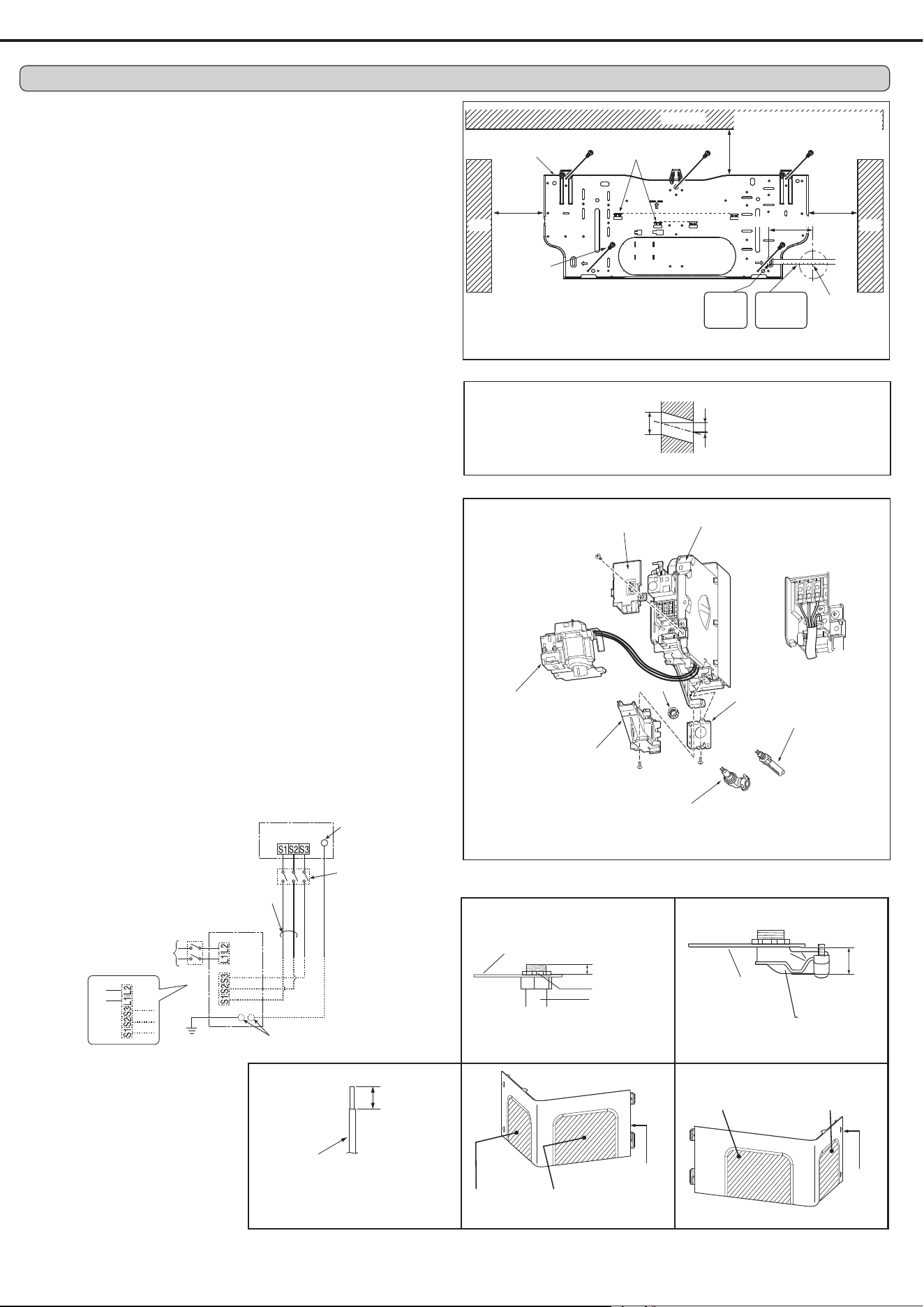
2-1. ATTACHING THE INSTALLATION PLATE
)LQGDVWXGLQWKHZDOOWRDWWDFKLQVWDOODWLRQSODWHKRUL]RQWDOO\E\ WLJKWHQLQJWKH¿[LQJ
VFUHZV¿UPO\
• To prevent installation plate (1) from vibrating, be sure to install the attachment screws in
the holes indicated in the illustration. For added support, additional screws may also be
installed in other holes.
• When the indoor unit is to be attached to a concrete wall using recessed bolts, secure
installation plate (1) using 7/16 in. x 13/16 in. · 7/16 in. x 1 in. (11 mm × 20 mm · 11 mm ×
26 mm) oval hole (17-3/4 in. [450 mm] pitch).
,IWKHUHFHVVHGEROWLVWRRORQJFKDQJHLWIRUDVKRUWHURQH¿HOGVXSSOLHG
Wall
Outdoor side
2-2. DRILLING
1) Determine where the holes will be located on the wall.
2) Drill a ø3 in. (75 mm) hole. The outdoor side should be 6/32 to 9/32 in. (5 to 7 mm) lower
than the indoor side.
3) Insert wall hole sleeve (C).
2-3. CONNECTING WIRES FOR INDOOR UNIT
Note:
The unit should be installed by a licensed contractor/electrician. If required by applicable
national, state and local codes; a disconnect switch will need to be installed when the
indoor unit is powered from the outdoor unit.
1) Remove the panel assembly. (Refer to 5-1.)
2) Place the upper part of the indoor unit on the installation plate.
3) Remove corner box and electrical cover.
4) Remove display and i-see sensor assembly, conduit cover and conduit plate.
5) Attach straight joint (for rear piping) / elbow joint (for right, left, or downward piping) to
conduit plate with lock nut. The thread of the installed conduit pipe / elbow joint appearing
inside should be less than 3/8 in. (10 mm). (Fig. 1) Elbow joint should appear less than
1-3/16 in. (30 mm) outside. (Fig. 2)
6) Process the end of ground wire (Fig. 3). Connect it to the ground terminal of electrical parts
box.
7) Process the end of indoor/outdoor unit connecting wire (A) (Fig. 3). Attach it to the terminal
block. Be careful not to make mis-wiring. Attach the wire to the terminal block securely so
that its core cannot be seen, and no external force affects the connecting section of the
terminal block.
8) Firmly tighten the terminal screws. After tightening, verify that the wires are tightly fastened.
9) Reinstall conduit plate, conduit cover and display panel.
10) According to the piping direction, remove the shaded part of the corner box L (Fig. 4) or
corner box R (Fig. 5). Reinstall electrical cover, corner box R and front panel.
Less than 3/8 in.
(10 mm)
Conduit plate
Conduit pipe or
elbow joint
Lock nut
6/32-9/32 in.
(5-7 mm)
ø3 in.
(75 mm)
Lead
wire
19/32 in.
(15 mm)
Indoor terminal
block
Fixing
screw
Conduit cover
Lock nut
Conduit plate
Elbow joint
(for right, left, or downward piping)
Elbow joint
(for right, left, or downward piping)
Less than 1-3/16 in.
(30 mm)
Corner
box R
Remove corner box
R for piping on right
side of unit
Remove corner box R
for piping on bottom
side of unit
Fig. 1 Fig. 2
Fig. 3 Fig. 4 Fig. 5
Coner
box L
Remove coner
box L for piping
on left side of unit
Remove coner box L
for piping on bottom
left side of unit
Level
Installation plate (1)
Center of ø3 in.
(75 mm) hole
5-1/4 in.
(132.5 mm)
or more
4-7/8 in.
(122.5 mm)
or more
3-3/8 in. (85 mm) or more
5-11/16 in. (143 mm) or more for left/
left rear piping (using spacer)
Ceiling
Wall
Attachment
screw (2)
* Same for left hole.
4-3/4 in. (120 mm)
INDOOR UNIT
Terminal block
208/230 V AC
1phase, 60 Hz
Grounding
terminal**
Disconnect
switch*
OUTDOOR UNIT
Grounding terminal**
Ground
Power supply 208/230 V AC,
1phase 2wires.
60 Hz
Terminal
block 1
Terminal
block
Terminal block 2
Electrical cover
Electrical box
Display and i-see
sensor assembly
Straight joint
(for rear piping)
Conduit plate
or
Wall
2. INDOOR UNIT INSTALLATION
Insert
the
scale. *
Align the
scale with
the line. *
FS15/18
FS06/09/12
Remark:
* A disconnect switch
should be required.
Check the local code.
** Use a ring tongue termi-
nal in order to connect a
ground wire to terminal.
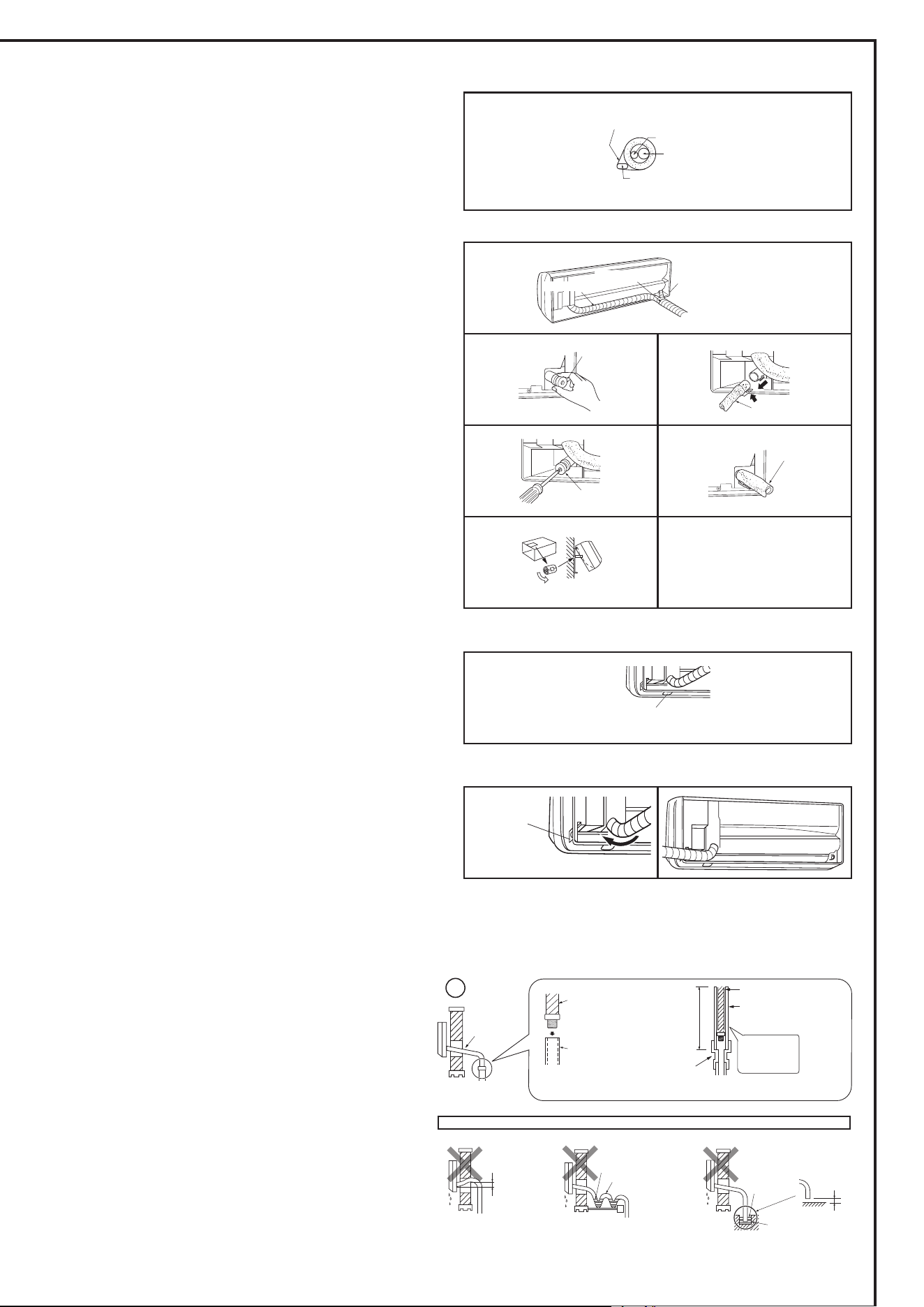
2-4-2. DRAIN PIPING
• If the extension drain hose has to pass through a room, be sure to wrap it with insula-
WLRQ¿HOGVXSSOLHG
• The drain hose should point downward for easy drain. (Fig. 1)
,IWKHGUDLQKRVHSURYLGHGZLWKWKHLQGRRUXQLWLVWRRVKRUWFRQQHFWLWZLWKD¿HOGVXSSOLHG
drain hose (I). (Fig. 2)
• When connecting the drain hose to a hard vinyl chloride pipe, be sure to insert it
securely into the pipe. (Fig. 3)
Do not make drain piping as shown below.
Do not raise
Accumulated
drain water
Air
Waving
Water
leakage
Water
leakage
Water
leakage
Tip of drain
hose dipped
in water
Ditch
At least
1-31/32 in.
(50 mm)
gap
Downward
slope
Drain
hose
Soft hose
I.D. 19/32 in.
(15 mm)
Drain hose
Hard vinyl chloride pipe
I.D. 1-3/16 in.
(30 mm)
Insert
securely
Different
diameter
joint
27-9/16 in.
(70 cm)
or more
Fig. 1 Fig. 2 Fig. 3
Liquid pipe
Gas pipe
Felt tape (4)
Indoor/outdoor unit
connecting wire (A)
Piping tape (G)
2-4. PIPE FORMING AND DRAIN PIPING
2-4-1. PIPE FORMING
• Place the drain hose below the refrigerant piping.
• Make sure that the drain hose is not crowded or bent.
• Do not pull the hose when applying the tape.
• When the drain hose passes the room, be sure to wrap it with insulation material
¿HOGVXSSOLHG
Note:
Make sure not to damage the cover of refrigerant pipe when attaching it back on with
screws.
Left or left-rear piping
Note:
Be sure to reattach the drain hose and the drain cap if the piping is being installed on
left or bottom left of unit, otherwise, water could drip down from the drain hose.
3ODFHWKHUHIULJHUDQWSLSLQJDQGWKHGUDLQKRVHWRJHWKHUWKHQ¿UPO\DSSO\IHOWWDSH
from the end.
Felt tape (4) overlap width should be 1/3 the tape width. Use a bandage stopper at the
end of felt tape (4).
2) Pull out the drain cap at the back right of the indoor unit. (Fig. 1)
• Hold the convex section at the end and pull the drain cap.
3) Pull out the drain hose at the back left of the indoor unit. (Fig. 2)
• Hold the claw marked by the arrows and pull out the drain hose forward.
4) Put the drain cap into the section to which the drain hose is to be attached at the rear
of the indoor unit. (Fig. 3)
• Insert a screwdriver into the hole on the cap and insert the cap fully into the
drain pan.
5) Insert the drain hose fully into the drain pan at the back right of the indoor unit. (Fig. 4)
• Check if the hose is hooked securely to the projection of its inserting part at the
drain pan.
6) Insert the drain hose into wall hole sleeve (C), and attach the upper part of indoor unit
onto the installation plate (1). Then, shift the indoor unit completely to the left to make
placing the piping in the back of the unit easier.
7) Cut out a piece of cardboard from the shipping box, roll it up, hook it onto the back rib,
and use it as a spacer to lift the indoor unit. (Fig. 5)
8) Connect the refrigerant piping with the extension pipe (B).
9) Attach the lower part of the indoor unit into the installation plate (1).
Remove panel for piping
on left side of unit.
Drain cap
Drain hose
Drain cap
Drain hose
Fig. 1 Fig. 2
Fig. 3
Fig. 4
Fig. 5
Piping tape (G)
Felt tape (4)
Rear or bottom piping
3ODFHWKHUHIULJHUDQWSLSLQJDQGWKHGUDLQKRVHWRJHWKHUWKHQ¿UPO\DSSO\SLSLQJWDSH
(G) from the end.
2) Insert the piping and the drain hose into the wall hole sleeve (C), and attach the upper
part of the indoor unit on the installation plate (1).
3) Check if the indoor unit is attached securely on the installation plate (1) by moving the
unit to left and right.
4) Attach the lower part of the indoor unit into the installation plate (1).
Right piping
Note:
Before performing the following, make sure that wiring is completed, and the conduit
cover is installed. (Refer to 2-3.)
1) Place the refrigerant piping and the drain hose together, shift them to left side of the
XQLWDQGWKHQ¿UPO\DSSO\SLSLQJWDSH*IURPWKHHQG
2) Insert the piping and the drain hose into the wall hole sleeve (C), and attach the upper
part of the indoor unit on the installation plate (1).
3) Check if the indoor unit is attached securely on the installation plate (1) by moving the
unit to left and right.
4) Attach the lower part of the indoor unit into the installation plate (1).
To the left
Remove corner
box for piping
on right side
of unit
Remove corner box for piping
on bottom side of unit
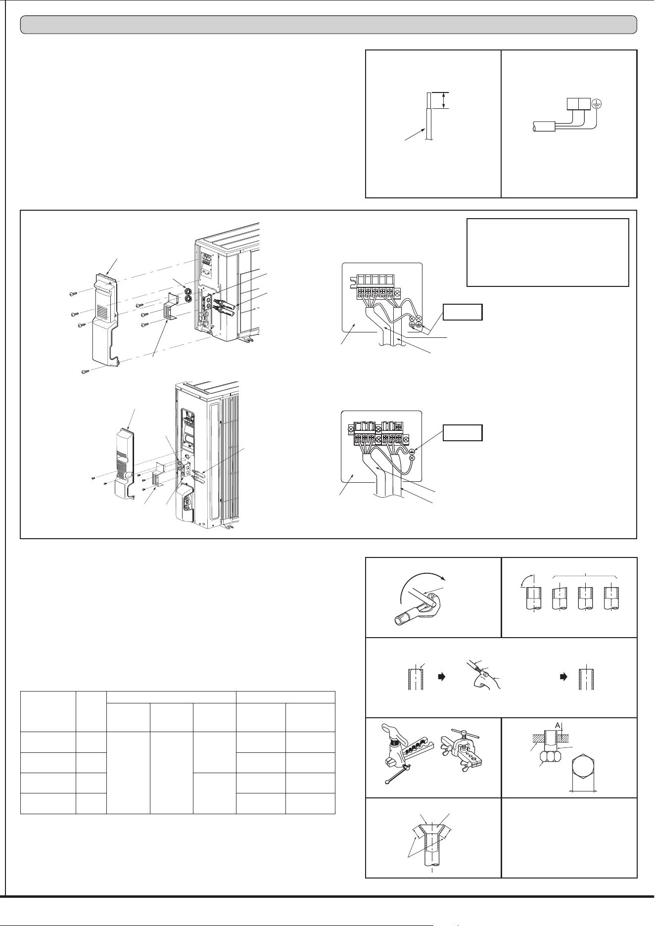
3-1. CONNECTING WIRES FOR OUTDOOR UNIT
1) Remove the service panel.
2) Remove the conduit cover.
3) Attach the conduit connectors to the conduit plate with lock nuts then secure it against unit with
screws.
4) Connect the ground wires of indoor/outdoor unit connecting wire (A) and power supply cord (K)
to the TB support.
5) Loosen the terminal screws, then attach indoor/outdoor unit connecting wire (A) and power sup-
ply cord (K) from the indoor unit correctly to the terminal block. Attach the wires to the terminal
block securely so that the cores cannot be seen, and no external force affects the connecting
section of the terminal block.
6) Firmly tighten the terminal screws. After tightening, verify that the wires are tightly fastened.
7) Install the conduit cover.
8) Install the service panel securely.
3-2. FLARE CONNECTION
1) Cut the copper pipe as straight as possible with a pipe cutter. (Fig. 1, 2)
2) Remove all burrs from the cut section of the pipe, ensuring that precautions are taken to avoid
getting metal shavings into the piping. (Fig. 3)
5HPRYHÀDUHQXWVDWWDFKHGWRLQGRRUDQGRXWGRRUXQLWVWKHQSXWWKHPRQSLSH
4) Flaring work (Fig. 4, 5). Firmly hold copper pipe in the dimension shown in the table. Select A
inch (mm) from the table according to the tool you use.
5) Check
&RPSDUHWKHÀDUHGZRUNZLWK)LJ
,IÀDUHLVGHIHFWLYHFXWRIIWKHVHFWLRQDQGUHSHDWSURFHGXUH
Terminal block
Power supply cord (K)
Indoor/outdoor unit
connecting wire (A)
• Make ground wire a little longer than others.
(More than 4 in. [100 mm])
• For future servicing, leave some slack in the
connecting wires.
• Be sure to attach each screw to its corre-
spondent terminal when securing the cord
and/or the wire to the terminal block.
Pipe diameter
inch (mm)
B inch
(mm)
A inch (mm) Tightening torque
Clutch
type tool
for R410A
Clutch
type tool
for R22
Wing nut
type tool
for R22
ft-lb
(kgf•cm)
N•m
ø1/4 (6.35)
21/32
(17)
0 to 0.02
(0 to 0.5)
0.04 to
0.06
(1.0 to 1.5)
0.06 to
0.08
(1.5 to 2.0)
10 to 13
(140 to 180)
13.7 to 17.7
ø3/8 (9.52)
7/8
(22)
25 to 30
(350 to 420)
34.3 to 41.2
ø1/2 (12.7)
1-1/32
(26)
0.08 to
0.10
(2.0 to 2.5)
36 to 42
(500 to 575)
49.0 to 56.4
ø5/8 (15.88)
1-5/32
(29)
54 to 58
(750 to 800)
73.5 to 78.4
Power supply cord (K)
L1
L2
Service panel
Lock nut
Conduit cover
Conduit plate
Conduit pipe
Grounding
terminal
Copper
pipe
Good
90°
Tilted
No good
Fig. 1 Fig. 2
Burr
Copper pipe
Spare reamer
Pipe cutter
Fig. 4
Fig. 3
Smooth all around
Even length
all around
Inside is shin-
ing without any
scratches.
Fig. 5
Fig. 6
Clutch type
Flaring tool
Wing nut type
Uneven Burred
TB support
<FS06/09/12>
<FS15/18>
Terminal block
to conduit cover
Power supply cord (K)
Indoor/outdoor unit
connecting wire (A)
TB support
Grounding
terminal
Service panel
Lock nut
Conduit cover
Conduit
plate
Conduit pipe
B
Flare nut
Die
Copper pipe
to conduit cover
Lead
wire
19/32 in.
(15 mm)
3. OUTDOOR UNIT INSTALLATION
3-3. PIPE CONNECTION
)DVWHQÀDUHQXWZLWKDWRUTXHZUHQFKDVVSHFL¿HGLQWKHWDEOHUHIHUWR
:KHQIDVWHQHGWRRWLJKWÀDUHQXWPD\HYHQWXDOO\EUHDNDQGFDXVHUHIULJHUDQWOHDNDJH
• Be sure to wrap insulation around the piping. Direct contact with the bare piping may result
in burns or frostbite.
Indoor unit connection
Connect both liquid and gas pipings to indoor unit.
$SSO\DWKLQFRDWRIUHIULJHUDWLRQRLO-RQWKHÀDUHGHQGVRIWKHSLSHV'RQRWDSSO\UH-
frigeration oil on screw threads. Excessive tightening torque will result in damage on the
screw.
7RFRQQHFW¿UVWDOLJQWKHFHQWHUWKHQWLJKWHQWKH¿UVWWRWXUQVRIÀDUHQXWE\KDQG
• Use tightening torque table above as a guideline for indoor unit side joints, and tighten
XVLQJWZRZUHQFKHV([FHVVLYHWLJKWHQLQJGDPDJHVWKHÀDUHVHFWLRQ
Outdoor unit connection
Connect pipes to stop valve pipe joint of the outdoor unit following the same procedure
detailed in Indoor unit connection.
• For tightening, use a torque wrench or spanner.
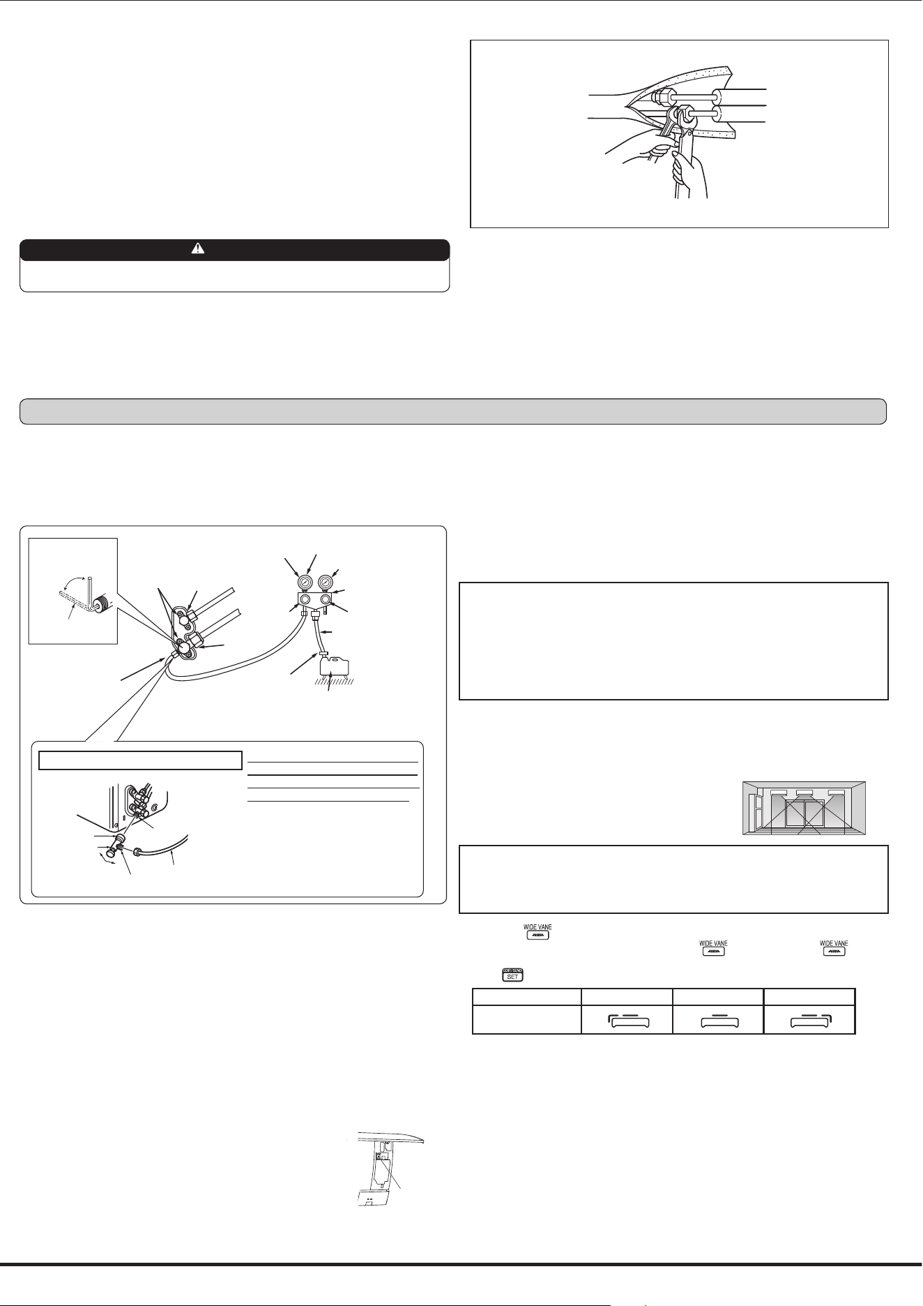
4-1. PURGING PROCEDURES AND LEAK TEST
1)
Remove service port caps from stop valves on both sides of refrigerant lines. (The stop
valves are fully closed when shipped.) Leave closed.
2) Connect gauge manifold to ports of stop valves.
4-5. EXPLANATION TO THE USER
• Using the OPERATING INSTRUCTIONS, explain to the user how to use the air conditioner
WKHUHPRWHFRQWUROOHUUHPRYLQJWKHDLU¿OWHUVSODFLQJRUUHPRYLQJWKHUHPRWHFRQWUROOHUIURP
the remote controller holder, cleaning methods, precautions for operation, etc.)
• Recommend that the user read the OPERATING INSTRUCTIONS carefully.
Stop valve for
GAS
Stop valve cap
(Torque 15 to
22 ft-lb, 19.6 to
29.4 N•m, 200
WRNJIƒFP
Vacuum pump (or the vacuum
pump with the function to
SUHYHQWWKHEDFNÀRZ
Gauge manifold valve
(for R410A)
Compound pressure gauge
(for R410A)
–14.7 psi [Gauge]
(–0.101 Mpa)
Handle
Low
Handle High
Adapter for
preventing the
EDFNÀRZ
Charge hose
(for R410A)
*Close
*Open
Hexagonal wrench
Precautions when using the control valve
When attaching the control valve to
the service port, valve core may de-
form or loosen if excess pressure is
applied. This may cause gas leak.
Service port
Charge hose
Body
Close
Open
Control valve
A
When attaching the control valve to
the service port, make sure that the
valve core is in closed position, and
then tighten part A. Do not tighten
part A or turn the body when valve
core is in open position.
Service port cap
(Torque 10 to 13 ft
-Ib, 13.7 to 17.7 N•m,
140 to 180 kgf•cm)
*4 to 5 turns
3) Evacuate the system to 4000 microns from both service valves. System manifold gauges
must not be used to measure vacuum. A micron gauge must be used at all times. Break
the vacuum with Nitrogen(N2) into the discharge service valve to 0 PSIG.
4) Evacuate the system to 1500 microns. Break the vacuum with Nitrogen(N2) into the
discharge service valve to 0 PSIG.
5) Evacuate the system to 500 microns.
6) Close gauge manifold valves, stop the pump, and conduct a 30 minute rise test.
7) System should hold 500 microns for a minimum of 1 hour.
8) Fully open all stop valves on both sides of gas pipe and liquid pipe. Operating without fully
opening lowers the performance and this causes trouble.
9) Refer to 1-3 and charge the prescribed amount of additional refrigerant if needed. Be
sure to charge slowly with liquid refrigerant. Otherwise composition of the refrigerant in
the system may be changed and affect performance of the air conditioner.
10) Remove gauge manifolds and replace service port caps and tighten.
11) Leak test
4-2. TEST RUN
1) Insert power supply plug into the power outlet and/or turn on the
breaker.
2) Press the E.O. SW once for COOL, and twice for HEAT operation.
Test run will be performed for 30 minutes. If the left lamp of the
operation indicator blinks every 0.5 seconds, inspect the indoor/
outdoor unit connecting wire (A) for mis-wiring. After the test run,
emergency mode (set temperature 75°F [24°C]) will start.
3) To stop operation, press the E.O. SW several times until all LED
lamps turn off. Refer to operating instructions for details.
Stop valve for LIQUID
Pressure gauge
(for R410A)
Checking the remote (infrared) signal reception
Press the ON/OFF button on the remote controller (3) and listen for an audible indicator
from the indoor unit. Press the ON/OFF button again to turn the air conditioner off.
• Once the compressor stops, the restart preventive device operates so the compressor will
not operate for 3 minutes to protect the air conditioner.
4-3. AUTO RESTART FUNCTION
This product is equipped with an auto restart function. When the power supply is cut off
during operation, such as during blackouts, the function automatically starts operation in
the previous setting once the power supply is resumed. (Refer to the operating instructions
for details.)
Caution:
• After test run or remote signal reception check, turn off the unit with the E.O. SW or the
remote controller before turning off the power supply. If this procedure is not performed,
the unit will automatically begin operation when power supply is resumed.
To the user
• After installing the unit, explain to the user about auto restart function.
• If auto restart function is unnecessary, it can be deactivated. Consult the service rep-
resentative to deactivate the function. Refer to the service manual for details.
3-4. INSULATION AND TAPING
1) Cover piping joints with pipe cover.
2) For outdoor unit side, insulate the piping, including valves.
3) Apply piping tape (G) starting from the connection on the outdoor unit.
• When piping has to be installed through a ceiling, closet or where the temperature and
KXPLGLW\DUHKLJKXVHDGGLWLRQDO¿HOGVXSSOLHGLQVXODWLRQWRSUHYHQWFRQGHQVDWLRQ
WARNING
When installing the unit, securely connect the refrigerant pipes before starting
the compressor.
4-4. SETTING THE INSTALLATION POSITION
Be sure to set the remote controller in accordance with the installed position of the indoor
unit.
Installation position:
Left: Distance to objects (wall, cabinet, etc.) is less
than 19-11/16 in. (50 cm) to the left
Center: Distance to objects (wall, cabinet, etc.) is
more than 19-11/16 in. (50 cm) to the left and right
Right: Distance to objects (wall, cabinet, etc.) is less
than 19-11/16 in. (50 cm) to the right
(Left) (Center)(Right)
Note:
The installation position can be set only when all the following conditions are met:
• The remote controller is powered off.
• Weekly timer is not set.
• Weekly timer is not being edited.
1) Hold down on the remote controller for 2 seconds to enter the position setting mode.
2) Select the target installation position by pressing
. (Each press of the displays
WKHSRVLWLRQVLQRUGHUFHQWHUĺULJKWĺOHIW
3) Press
to complete the position setting.
Installation position Left Center Right
Remote controller
display
Emergency
operation
switch
(E.O. SW)
4. PURGING PROCEDURES, LEAK TEST, AND TEST RUN
5-3. PUMPING DOWN
When relocating or disposing of the air conditioner, pump down the system following
the procedure below so that refrigerant is not released into the atmosphere.
1) Connect the gauge manifold valve to the service port of the stop valve on the gas pipe
side of the outdoor unit.
2) Fully close the stop valve on the liquid pipe side of the outdoor unit.
3) Close the stop valve on the gas pipe side of the outdoor unit almost completely so that
it can be easily closed fully when the pressure gauge shows 0 psi [Gauge] (0 Mpa).
4) Start the emergency COOL operation.
To start the emergency operation in COOL mode, disconnect the power supply plug
and/or turn off the breaker. After 15 seconds, connect the power supply plug and/or turn
on the breaker, and then press the E.O. SW once. (The emergency COOL operation
can be performed continuously for up to 30 minutes.)
5) Fully close the stop valve on the gas pipe side of the outdoor unit when the pressure
gauge shows (0.1 to 0 psi [Gauge] (0.05 to 0 Mpa)).
6) Stop the emergency COOL operation.
To stop operation, press the E.O. SW several times until all LED lamps turn off. Refer
to operating instructions for details.
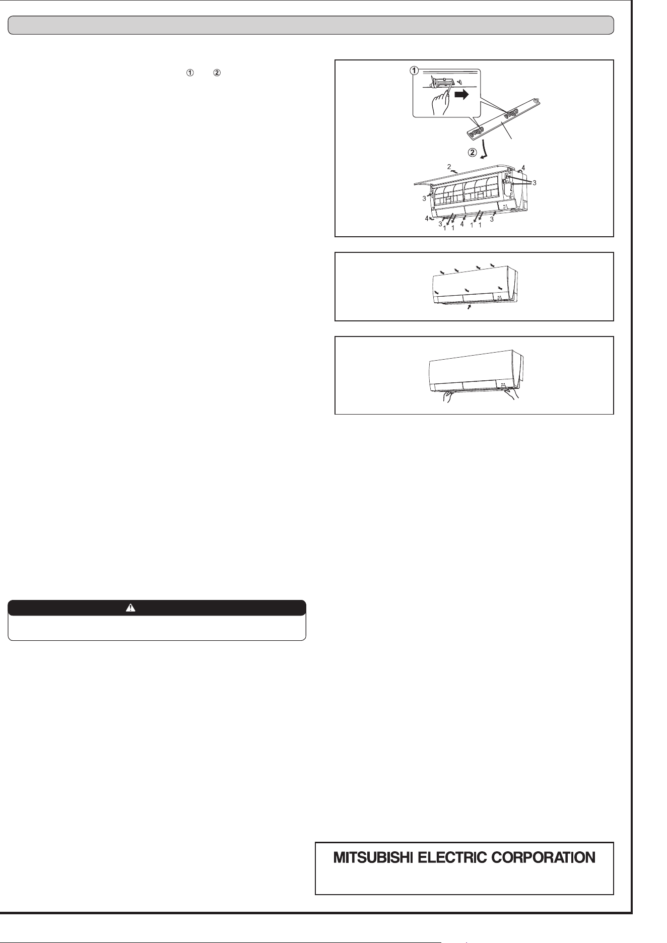
5-2. REMOVING THE INDOOR UNIT
Remove the bottom of the indoor unit from the installation plate.
When releasing the corner part, release both left and right bottom corner part of indoor
XQLWDQGSXOOLWGRZQZDUGDQGIRUZDUGDVVKRZQLQWKH¿JXUHRQWKHULJKW
Installation procedure
1) Install the panel assembly following the removal procedure in reverse.
2) Be sure to press the positions as indicated by the arrows in order to attach the assembly
completely to the unit.
3) Install the front panel and the horizontal vanes.
HEAD OFFICE: TOKYO BUILDING, 2-7-3, MARUNOUCHI, CHIYODA-KU,
TOKYO 100-8310, JAPAN
Upper and
lower vanes
Unlock
WARNING
When pumping down the refrigerant, stop the compressor before disconnecting
the refrigerant pipes. The compressor may burst if air etc. get into it.
5. RELOCATION AND MAINTENANCE
Removal procedure
1) Unlock the upper and lower vanes as shown in
and using a thin instrument.
Then, remove the horizontal vanes.
2) Remove the front panel.
5HPRYHWKHVFUHZVZKLFK¿[WKHSDQHODVVHPEO\
4) The panel assembly consists of 3 components. Remove them in the following order:
right, left, and center bottom. To remove the right component, pull out the right top
corner. To remove the left component, pull out the left bottom corner. To remove the
center bottom component, detach the hook on its upper center part.
5-1. REMOVING AND INSTALLING THE PANEL ASSEMBLY