Shenzhen Xtooltech Intelligent Co., LTD
USER MANUAL
Anyscan Wireless Scan Tool
This user manual is applicable to A30/A30D/A30M

I
Please read this user manual carefully before using the Anyscan Wireless Scan
Tool. When reading the manual, please pay attention to the words “Note” or
“Caution” and read them carefully for appropriate operation.
TRADEMARKS
and Anyscan® are the registered trademarks of Shenzhen Xtooltech
Intelligent CO., LTD.
In countries that the trademarks, service marks, domain names, logos, and the
name of the company are not registered, XTOOL claims that it still reserves the
ownership of the unregistered trademarks, service marks, domain names, logos,
and the company name. All other marks for the other products and the company’s
name mentioned in the manual still belong to the original registered company.
You may not use the trademarks, service marks, domain names, logos, and
company name of XTOOL or other companies mentioned without written
permission from the trademark holder.
XTOOL reserves the right to the final interpretation of this manual content.
COPYRIGHT
Without the written consent of Shenzhen Xtooltech Intelligent Co., Ltd., any
company or individual shall not copy or backup this operation manual in any form
(electronic, mechanical, photocopying, recording, or other forms).
DECLARATION
This manual is designed for the usage of the Anyscan Wireless Scan Tool and
provides operating instructions and product descriptions for users of the Anyscan
Wireless Scan Tool.
No part of this manual can be reproduced, stored in a retrieval system, or
transmitted, in any form or by any means (electronic, mechanical, photocopying,
recording, or otherwise), without the prior written permission of XTOOL.
Use the device only as described in this manual. XTOOL is not responsible for any

II
consequences of violating the laws and regulations caused by using the product or
its data information
XTOOL shall not be liable for any incidental or consequential damages or for any
economic consequential damages arising from the accidents of individual users
and the third parties, misuse or abuse of the device, unauthorized change or repair
of the device, or the failure made by the user not to use the product according to
the manual.
All information, specifications, and illustrations in this manual are based on the
latest configurations and functions available at the time of printing. XTOOL
reserves the right to make changes at any time without notice.
OPERATION INSTRUCTIONS
For safe operation, please follow the instructions below:
Keep the device away from heat or fumes when you are using it.
If the vehicle battery contains acid, please keep your hands and skin or fire
sources away from the battery during testing.
The exhaust gas of the vehicle contains harmful chemicals, please ensure
adequate ventilation.
Do not touch the cooling system components or exhaust manifolds when the
engine is running due to the high temperatures reached.
Make sure the car is securely parked, Neutral is selected or the selector is at P
or N position to prevent the vehicle from moving when the engine starts.
Make sure the (DLC) diagnostic link connector is functioning properly before
starting the test to avoid damage to the Diagnostic Tablet.
Do not switch off the power or unplug the connectors during testing, otherwise,
you may damage the ECU and/or the Diagnostic Tablet.

III
CAUTIONS
Avoid shaking or dismantling the unit as it may damage the internal
components.
Do not use hard or sharp objects to touch the LCD screen;
Do not use excessive force;
Do not expose the screen to strong sunlight for a long period.
Please keep it away from water, moisture, high temperature, or very low
temperature.
If necessary, calibrate the screen before testing to ensure the accuracy of LCD
performance.
Keep the main unit away from strong magnetic fields.
Please keep your device always connected to the Internet. When the device is
off the Internet for 30 days, The diagnosis APP may be locked and you need to
synchronize data with the Internet to activate it.
AFTERSALES-SERVICES
E-Mail: supporting@xtooltech.com
Tel: +86 755 21670995 or +86 755 86267858 (China)
Official Website: www.xtooltech.com
Please provide your device serial number, VIN code, vehicle model, software version, and other
details when seeking technical support.
If there are screenshots or videos, it will better help us locate your problem.

IV
CONTENTS
TRADEMARKS ......................................................................................................... I
COPYRIGHT ............................................................................................................. I
D
ECLARATION
.........................................................................................................I
O
PERATION
I
NSTRUCTIONS
.............................................................................. II
CAUTIONS ..............................................................................................................III
AFTERSALES-SERVICES ....................................................................................III
C
ONTENTS
............................................................................................................ IV
1 GENERAL INTRODUCTION ..............................................................................1
1.1 Function Description .................................................................................... 1
1.2 Main Menu ....................................................................................................2
1.3 Function Buttons .......................................................................................... 3
1.4 Technical Specifications ...............................................................................4
1.5 Wireless Communication .............................................................................4
1.6 Power Source ...............................................................................................4
2 G
ETTING
S
TART
............................................................................................... 5
2.1 Download & Install App ................................................................................5
2.2 Registration & Activation ..............................................................................6
2.3 Download & Update Software ..................................................................... 7
2.4 Vehicle Connection ...................................................................................... 8
2.5 Bluetooth Connection ...................................................................................8
2.6 VCI Status .................................................................................................... 9
2.7 Delete Software ......................................................................................... 10
3 D
IAGNOSIS
........................................................................................................11
3.1 Auto Scan ................................................................................................... 11
3.2 Diagnosis ....................................................................................................12

V
3.3 Diagnosis Functions ...................................................................................14
4 OBD II............................................................................................................... 21
5 SPECIAL FUNCTIONS .....................................................................................30
5.1 Oil Reset.....................................................................................................31
5.2 EPB ............................................................................................................ 34
5.3 SAS ............................................................................................................ 37
5.4 DPF ............................................................................................................ 41
5.5 BMS Reset ................................................................................................. 47
5.6 Throttle ....................................................................................................... 50
5.7 Injector Coding ...........................................................................................52
5.8 Gearbox Match ...........................................................................................56
5.9 Gear Learning ............................................................................................ 57
6 REPORTS .......................................................................................................... 60
6.1 Diagnosis Report ....................................................................................... 60
6.2 Data Playback ............................................................................................61
7 SETTING ............................................................................................................ 63
7.1 Language ................................................................................................... 64
7.2 Units ........................................................................................................... 65
7.3 Bluetooth .................................................................................................... 66
7.4 Workshop Information ................................................................................66
7.5 VCI Information.......................................................................................... 67
7.6 About .......................................................................................................... 68
8 FAQ....................................................................................................................69
Q1: Bluetooth pairing failed............................................................................. 69
Q2: Failed to generate diagnosis report ..........................................................69
Q3: Failed to extract files ................................................................................. 70
Q4: How to upgrade firmware ..........................................................................70
Q5: How to generate and upload diagnostic log files ..................................... 70
Q6: How to switch language ............................................................................71
Q7: Failed to diagnose vehicle ........................................................................ 71

VI
Q8: Failed to activate or register ..................................................................... 72
9 WARRANTY & SERVICES ............................................................................. 73
APPENDIX ............................................................................................................. 75
Legal Statement and Privacy Right Policy ...................................................... 75
—
1
—
1 GENERAL INTRODUCTION
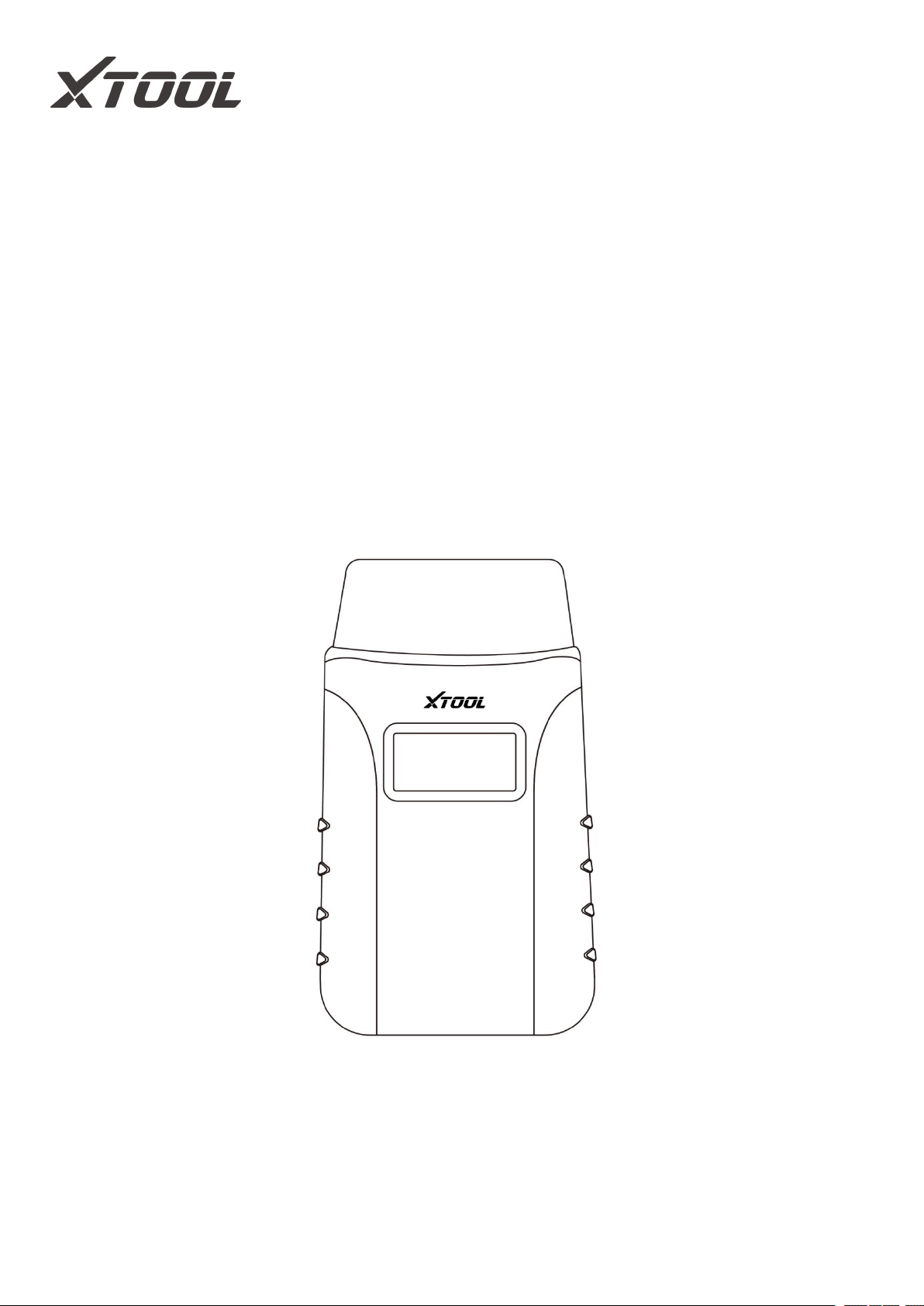
Anyscan is a full system scan tool and easily to carry in your pocket, working
together with mobile phones and tablets. Both iOS and Android platforms are
supported. The Anyscan package includes a Bluetooth OBDII connector and an
Anyscan application. It is a perfect DIY tool for customers to get a quick scan of all
systems and full brands are covered. It also includes numerous special functions,
such as service light reset, DPF regeneration, and EPB reset.
Figure 1-1 Product View
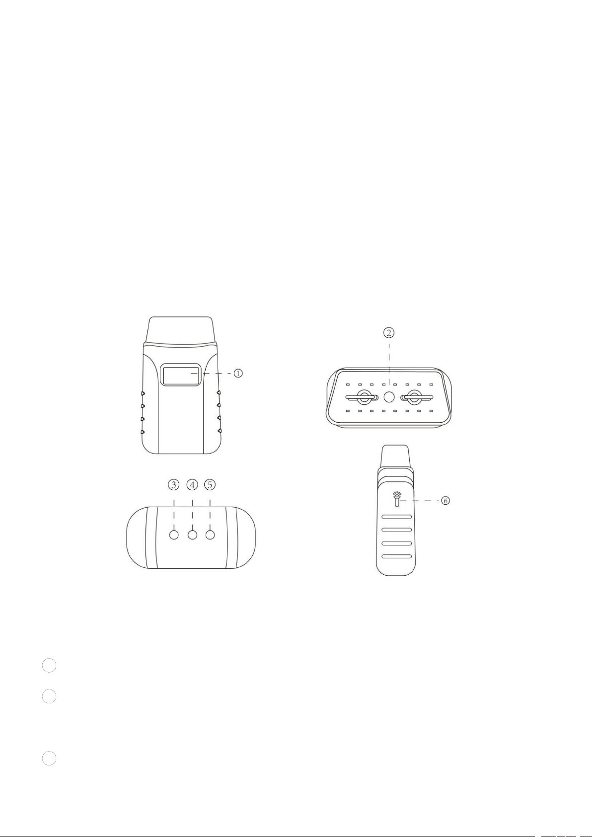
1.1 FUNCTION DESCRIPTION
1
Display - shows the operating voltage of the device
2
Vehicle Data Connector (OBD-16 pin) - connect the Anyscan to the vehicle’s
16-pin DLC directly
3
Bluetooth Indicator - Lights solid blue when the Anyscan is connected to the
—
2
—
mobile device through Bluetooth
4 Power Indicator - Lights solid red when the Anyscan is properly connected to
the vehicle/power supply
5 Vehicle Indicator - Lights flash green when the Anyscan is communicating
with the vehicle
6 Light Bulb - Press either button on both sides of Anyscan to light up the light
bulb installed in the 16-pin connector
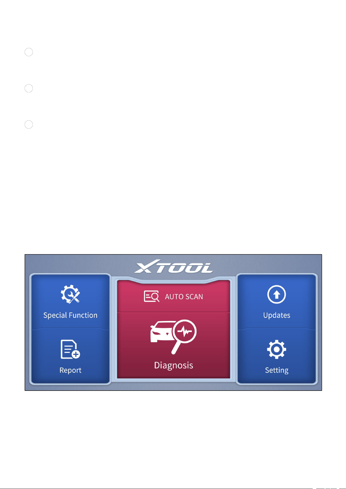
1.2 MAIN MENU
Every time you start the app, you will automatically enter the main screen shown
below. A detailed description of the menu structure can be found in the next section
Function Buttons.
Figure 1-2 Sample of the main menu screen
—
3
—
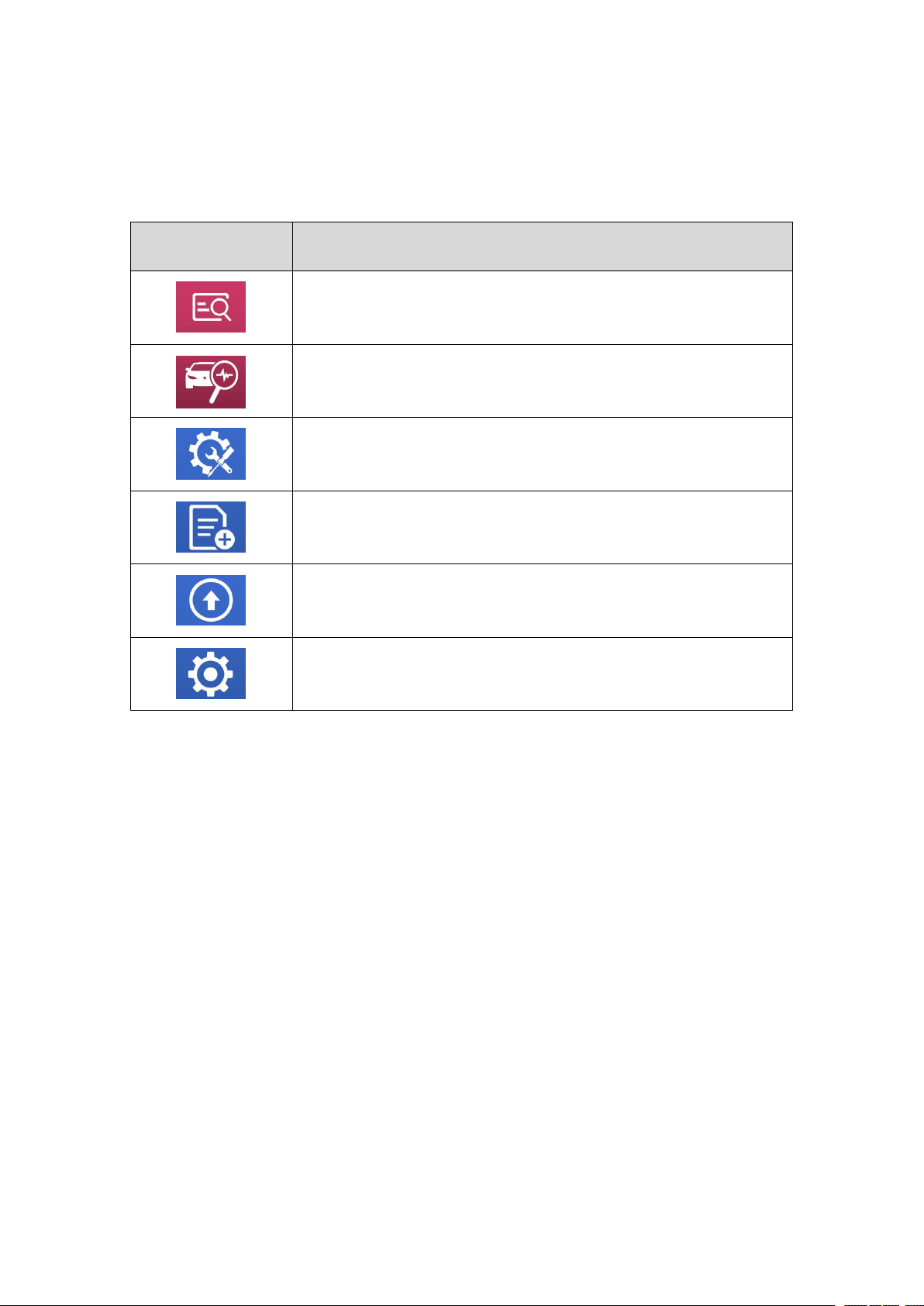
1.3 FUNCTION BUTTONS
The following table briefly describes each function button which can be found in the
main menu.
Icon
Description
Auto Scan for vehicle
Enter vehicle diagnosis menu
Includes various special functions for vehicles
Check the diagnosis report that recorded on your device,
prints it as PDF files, or share it with other devices
Update the diagnosis software through the Internet
Select the language and unit shown in the app, and check
the Bluetooth status, device info, and workshop info
Table 1-1 Description of function button

—
4
—
1.4 TECHNICAL SPECIFICATIONS
Item
Description
Display
1 inch
CPU
STM32
Interface
OBD interface
Bluetooth
3.0 / 4.0 compatible, + EDR dual mode
Memory
512KB
LED lights
Bluetooth indicator, power indicator, vehicle diagnostic
light, light indicator
Dimensions
87.00 * 50.00 * 25.00 mm (3.43 * 1.97 * 0.98 inches)
Lighting Power Supply
100mAh
Table 1-2 Specifications
1.5 WIRELESS COMMUNICATION
Anyscan uses Bluetooth communication. It can transmit vehicle data to your
Android or IOS device without a physical connection. The working range for
Bluetooth is around 10 m (32.81 ft.). Signal lost due to moving out of the range will
automatically be restored once the device is brought within transmission range to
the Anyscan connector.
1.6 POWER SOURCE
Anyscan operates on 12-volts vehicle power which it receives through the vehicle
data connection port. And the real-time operating voltage is shown on the display.
The unit powers on whenever it is connected to an OBDII compliant data link
connector (DLC).
—
5
—
2 GETTING START
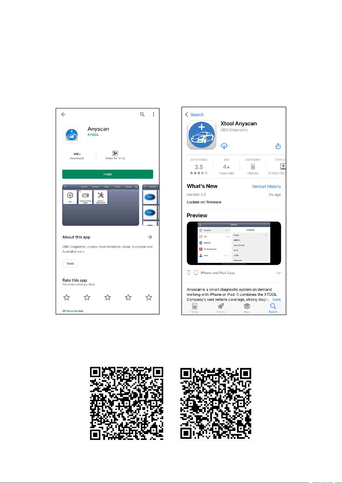
2.1 DOWNLOAD & INSTALL APP
Search for Anyscan Download in the Google Play or App Store to download and
install the app to your device.
Figure 2-1 Sample of APP downloading screens
OR scan the applicable QR codes shown below to download the Anyscan. You will
be directed to the corresponding downloading page like figure 2-1.
Anyscan - Google Play Anyscan - App Store

—
6
—
2.2 REGISTRATION & ACTIVATION
Enter the serial number, activation code, username, Email address, and password
into the corresponding input box. And press the Activation button to activate the
app.
Figure 2-2 Sample of activation screen
Figure 2-3 Sample of Certificate of Quality
Serial number - Can be found in the Certificate of Quality, back of the device, and
the outer packaging
Activation code - Can be found in the Certificate of Quality
Each account can be logged in with more than one mobile device, however, the Anyscan can
only connect to one mobile device at one time.
—
7
—
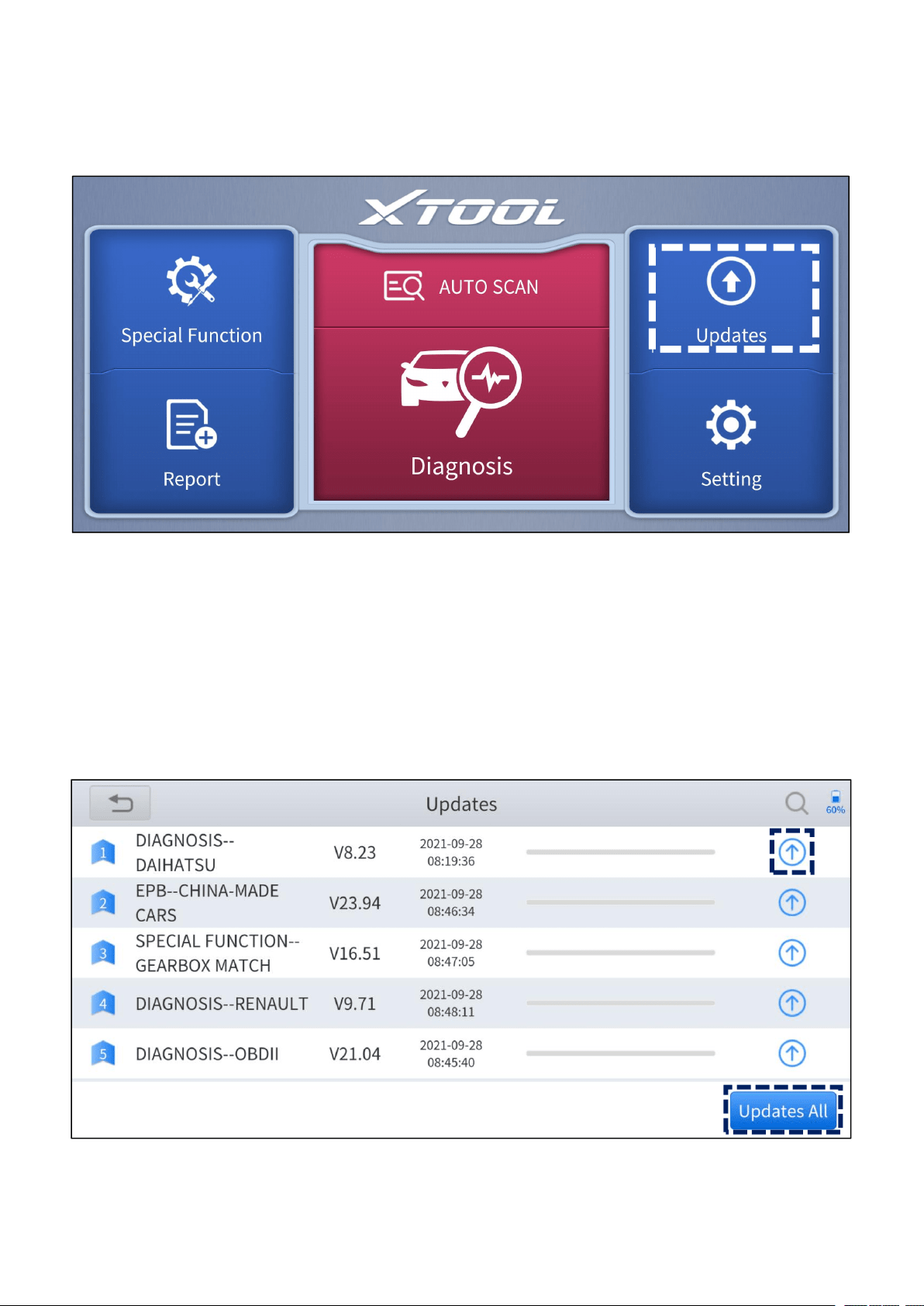
2.3 DOWNLOAD & UPDATE SOFTWARE
Click the Updates button to enter the updates interface.
Figure 2-4 Sample of the main menu screen
All the available software is shown on this page. You can choose to download the
specific software individually by pressing the arrow button next to the required
software or choose to upgrade all available software at once by pressing Updates
All.
Figure 2-5 Sample of updates interface
—
8
—
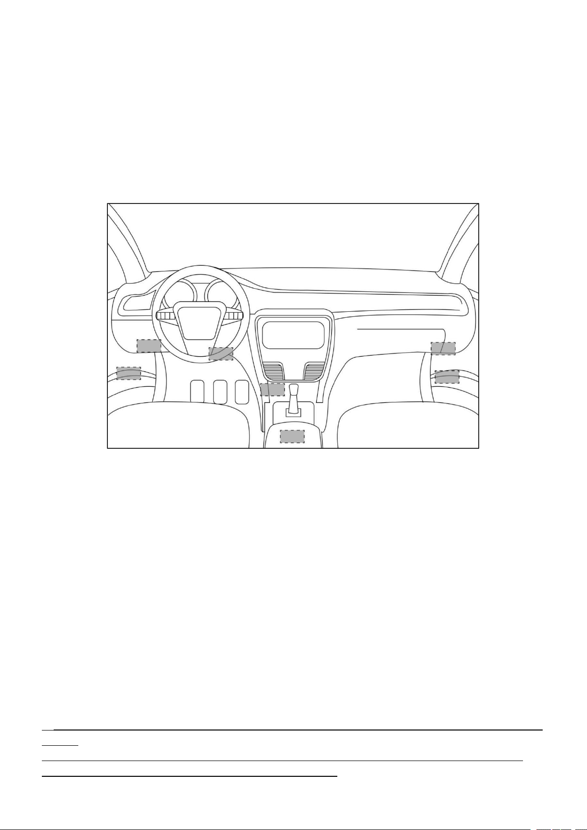
2.4 VEHICLE CONNECTION
Insert the Anyscan to the OBD port on the testing vehicle, diagram below shows
the common locations where the OBD port at. The flashlight equipped may help to
locate the OBD port. Red solid light will be shown on the power indicator if the
device is properly connected.
Figure 2-6 locations of OBD port
2.5 BLUETOOTH CONNECTION
Open the Bluetooth setting in Anyscan app, the device will be discovered as the
‘serial number’ of the Anyscan. Once the Anyscan is paired to any of the mobile
devices, it will be remembered by that device and automatically connected to it
when next time the Anyscan is connected to the vehicle/power supply. Blue solid
light will show on the Bluetooth indicator after the Bluetooth is successfully
connected.
You are only able to connect the Bluetooth after connecting the Anyscan to the vehicle/power
supply.
For Android users, you may need to pair the Anyscan device in the system setting of your
phone before you can connect the device within the app.

—
9
—
2.6 VCI STATUS
Figure 2-7 LED indicators
From left to right, the LED displays blue, red, and green light respectively, and each
of the LEDs indicate different operating status.
1
Bluetooth Indicator - Lights solid blue when the Anyscan is connected to the
mobile device through Bluetooth
2
Power Indicator - Lights solid red when the Anyscan is properly connected to
the vehicle/power supply
3
Vehicle Indicator - Lights flash green when the Anyscan is communicating
with the vehicle
The vehicle indicator will only light green when the Anyscan is sending or receiving commands
to or from the vehicle. It will not light green throughout the diagnosis process.
—
10
—
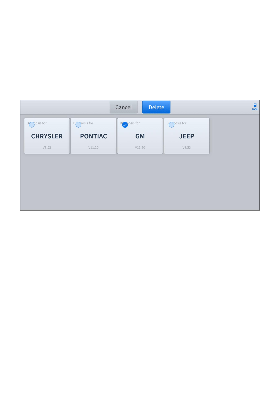
2.7 DELETE SOFTWARE
Long-press the unwanted software until it has been selected, then click the Delete
button shown on the upper part of the screen. And you can select and delete
multiple software at once.
Figure 2-8 Sample of software deleting screen
—
11
—
3 DIAGNOSIS
The diagnosis function can read ECU information, read and clear DTC and display
live data and freeze frame. The diagnosis function can also access the electronic
control unit (ECU) of all available vehicle control systems, including the engine,
transmission, anti-lock braking system (ABS), airbag system (SRS), body control
module (BCM), battery management system (BMS), tire pressure monitoring
system (TPMS), steering and suspension system (SAS) and perform various
actuation tests.
Diagnosis can only be performed when the Anyscan is connected to a mobile device through
Bluetooth successfully and the Bluetooth indicator lights solid blue.
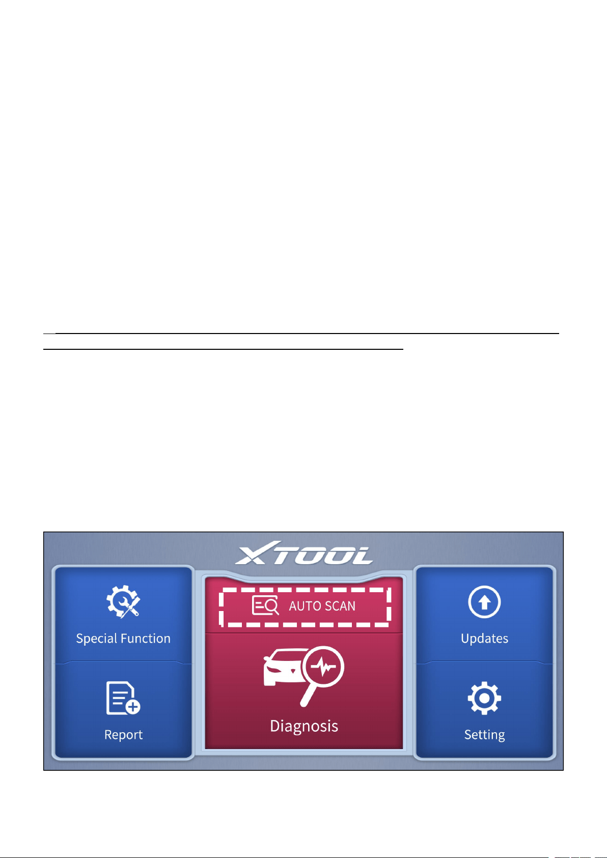
3.1 AUTO SCAN
Click the AUTO SCAN button, and the models and information will be scanned.
You have to select the corresponding options and confirm the vehicle information
scanned.
Figure 3-1 Sample of the main menu screen
—
12
—
You can choose to enter the Auto Diagnosis menu to get a quick scan of all
systems, the scanning process lasts around 2 to 3 minutes. OR you can enter the
System Diagnosis to test for specific modules or functions.
After clicking the AUTO SCAN, if the required software is not installed, you will be directed to
the updates page of that software.
Automatic Detection does not work on all cars. If ‘Automatic Detection’ fails, it does not
necessarily mean that your vehicle or the function is not supported, please navigate manually
and try again.
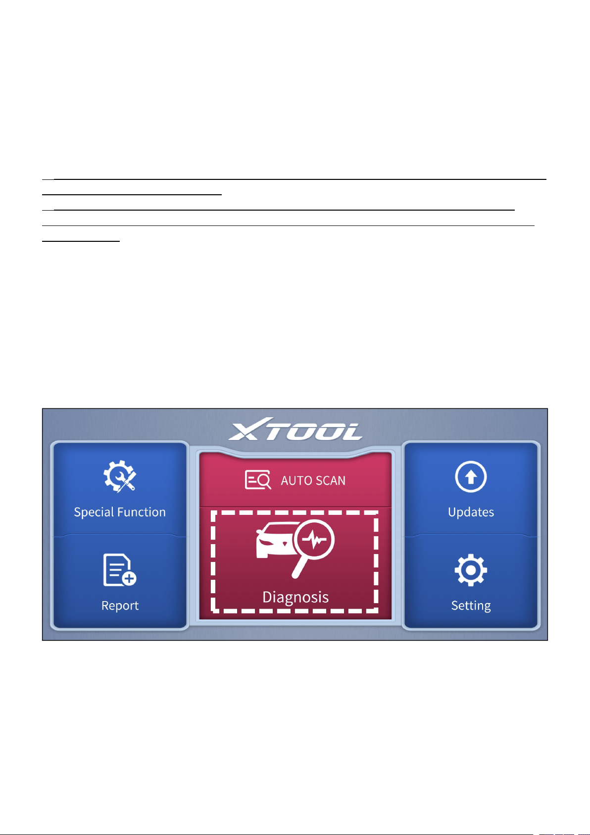
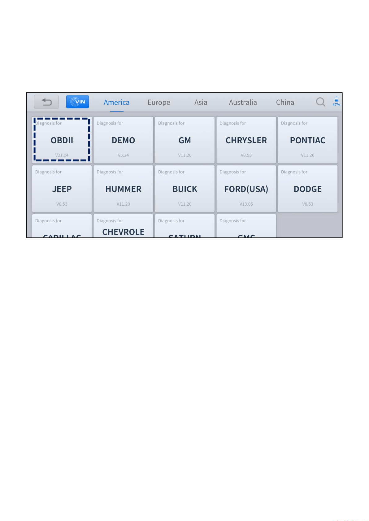
3.2 DIAGNOSIS
Click the Diagnosis button on the main screen and get into the diagnosis menu. All
the brands will be shown on the screen, you can select the region of your vehicle,
click the correct brand, and start the diagnosis process.
Figure 3-2 Sample of the main menu screen
For some of the vehicle brands (like Volkswagen), when you click on the software,
there are several ways to select the model or system you want to run a diagnosis,
including Automatic Detection, Manual Selection, and System Selection.

—
13
—
Figure 3-3 Sample of VW menu screen
Automatic Detection will automatically identify the vehicle’s VIN code, and then
read the information of your target diagnostic vehicle. (Same function as AUTO
SCAN on the main menu) If you choose Manual Selection, then you can continue
to select the vehicle brand, year, and model of the vehicle in the sub-menu to
diagnosis the vehicle. Enter System Selection, you can also diagnosis the vehicle
according to the system or your needs after selecting the models.
OBDII menu supports reading the common fault codes in the PCM. The DTCs may not be the
same when compared with using common diagnosis software.
DEMO is a demonstration program. You can perform basic diagnosis functions without
connecting to the car.
DEMO is only for demonstration purposes, the functions and interface are not necessarily the
same as the actual version of the software/App. Please activate and update your device to use
the latest version of software.
—
14
—
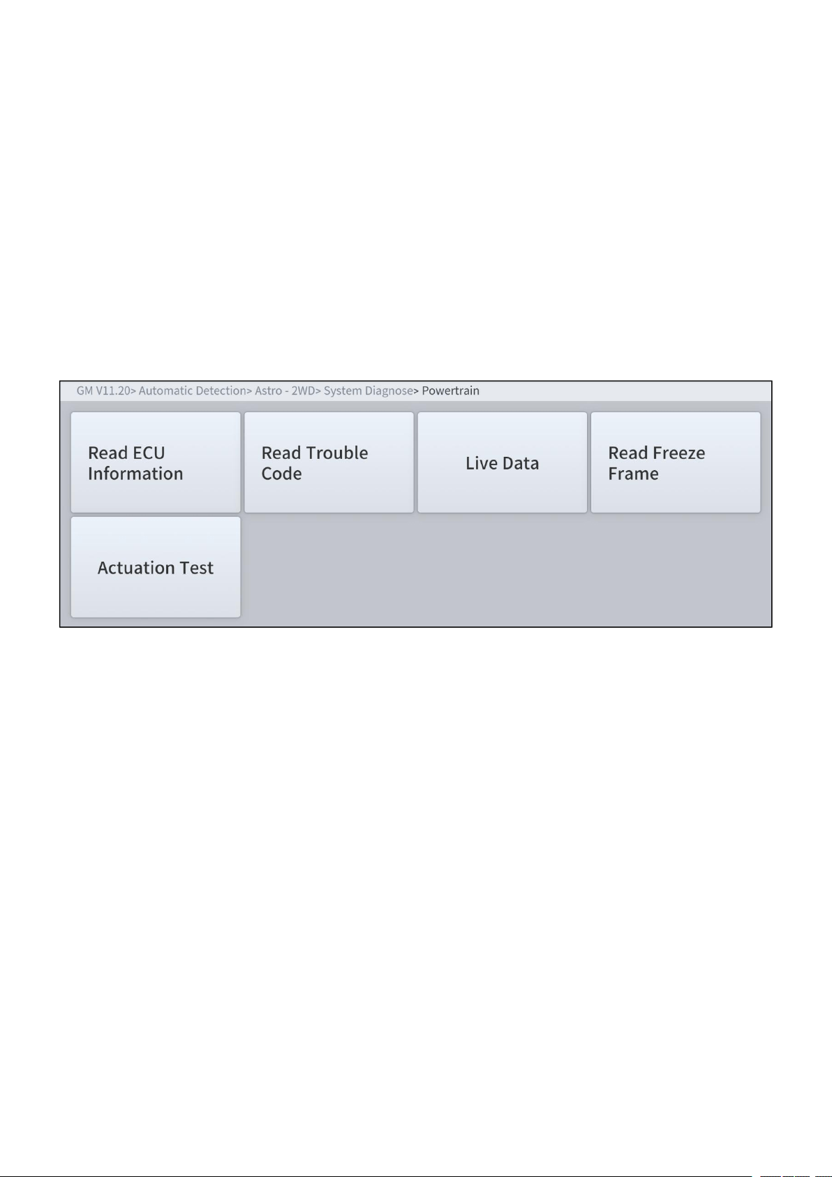
3.3 DIAGNOSIS FUNCTIONS
The Diagnosis System supports 5 basic diagnosis functions:
Read ECU Information
Read & Clear Trouble Code
Live Data
Actuation Test (Bi-Directional Control)
Freeze Frame
Figure 3-4 Five diagnosis functions
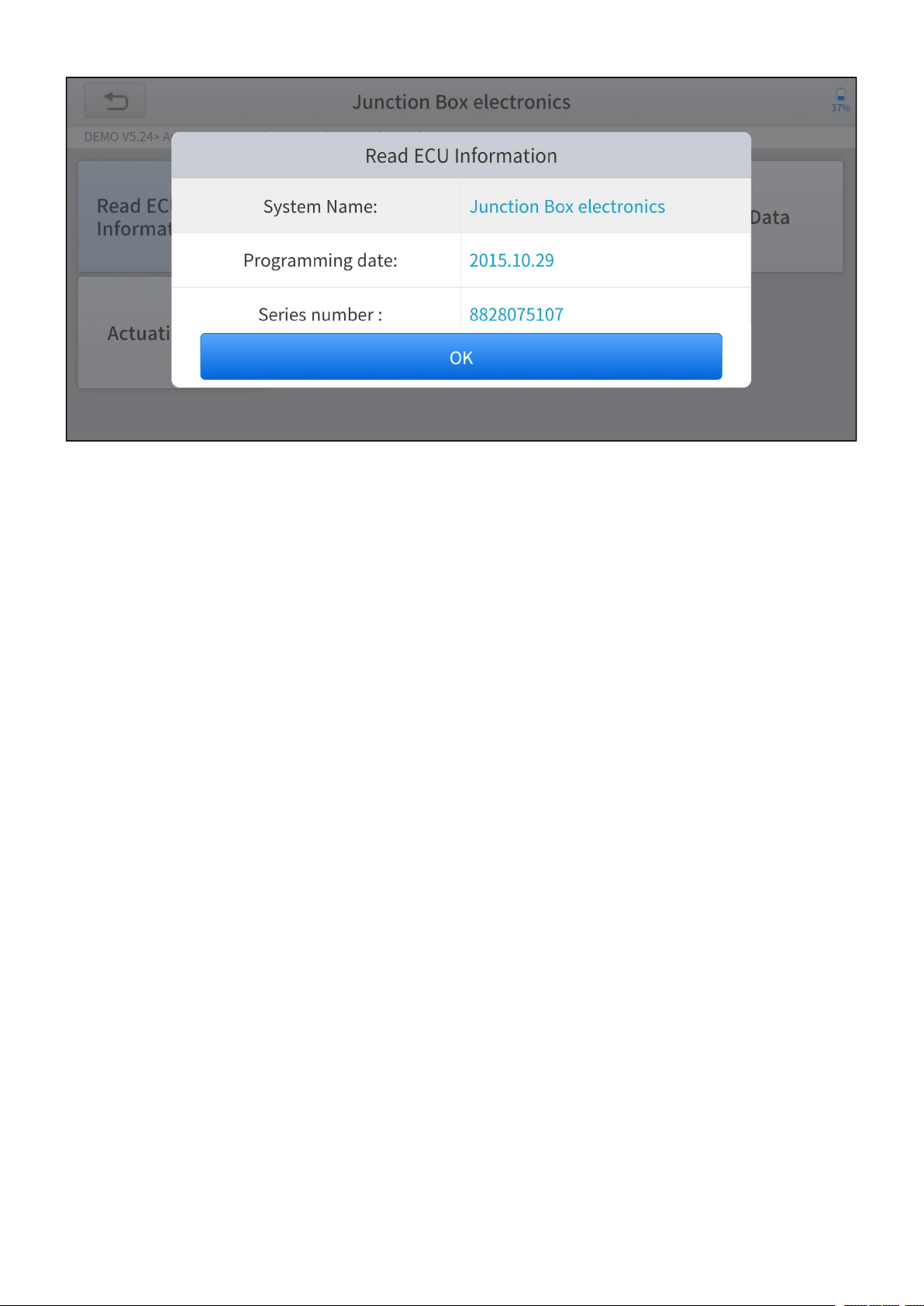
Read ECU Information
This function is to read ECU version information, which is the equivalent of System
Identification or System Information in some electronic control systems, which
means to read ECU-related software and hardware versions, models, and
production date of the diesel engine, part number, etc.
—
15
—
Figure 3-5 Sample of read ECU information screen
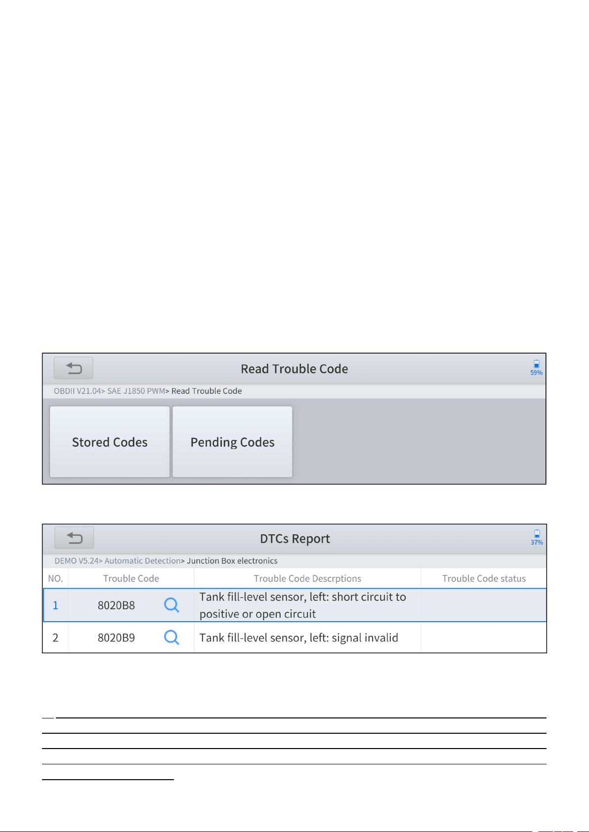
Read Trouble Code
Read trouble codes (DTCs) that are stored in ECU. For the trouble code, the
diagnostic instrument will give specific detailed definitions and explanations to help
you locate and eliminate the car fault.
Stored Code
Stored codes are the current emission-related DTCs from the ECM of the
vehicle. OBDII Codes have a priority according to their emission severity, with
higher priority codes overwriting lower priority codes. The priority of the code
determines the illumination of the MIL and the codes erase procedure.
Manufacturers rank codes differently, so expect to see differences between
makes.
Pending Code
These are codes whose setting conditions were met during the last drive cycle,
but need to be met two or more consecutive drive cycles before the DTC
—
16
—
actually sets. The intended use of this service is to assist the service
technician after a vehicle repair and after clearing diagnostic information, by
reporting test results after a driving cycle.
a. If a test failed during the driving cycle, the DTC associated with that test
is reported. If the pending fault codes do not occur again within 40 to 80
warm-up cycles, the fault is automatically cleared from memory.
b. Test results reported by this service do not necessarily indicate a faulty
component or system. If test results indicate another failure after
additional driving, then a DTC is set to indicate a faulty component or
system, and the MIL is illuminated.
Figure 3-6 Sample of read trouble code screen
Figure 3-7 Sample of DTCs Report
In the process of diagnosis, if the device shows “System is OK” or “No Trouble Code”, it
means there is no related trouble code stored in ECU. OR some troubles are not under the
control of ECU, most of these troubles are mechanical system troubles or executive circuit
troubles, it is also possible that the signal of the sensor may bias within limits, which can be
determined by Live Data.
—
17
—
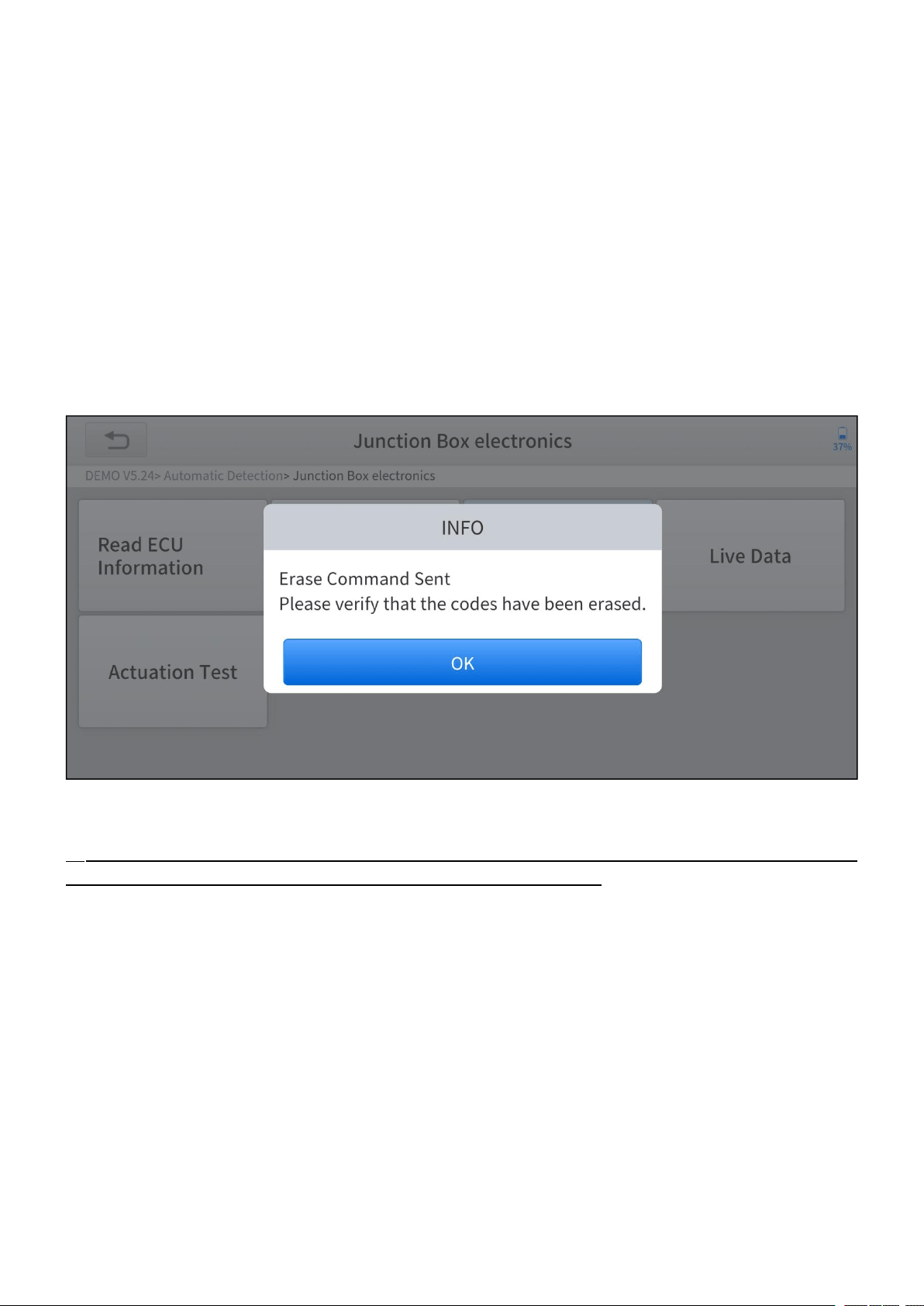
Clear Trouble Code
It allows clearing current and historical trouble codes (DTCs) memory in ECU,
under the premise that all the troubles are eliminated. There are two types of
trouble codes, one is permanent trouble code and the other is non-permanent
trouble code. The former requires manual troubleshooting of the car before it can
be cleared with a diagnostic tool. Non-permanent trouble codes can be cleared
directly with the diagnostic tool.
Figure 3-8 Sample of clear trouble code screen
The trouble codes cannot be cleared without eliminating all the troubles, the diagnostic tool
can always read those codes as those codes are saved in ECU.

—
18
—
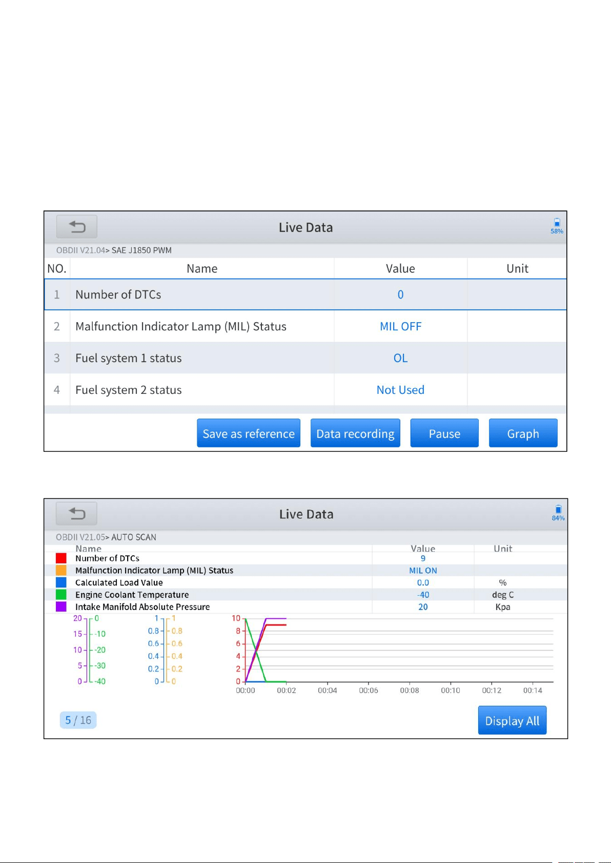
Live Data
This function displays the real-time parameters of the ECU, take the engine as an
example, parameters such as engine oil temperature, engine speed, ambient
pressure, coolant temperature, etc. can be read. The Scope of maintenance can
be narrowed down as we can determine the faulty component based on these
parameters. And the data can be displayed in various modes.
Figure 3-9 Sample of live data screen (table)
Figure 3-10 Sample of live data screen (graph)
—
19
—
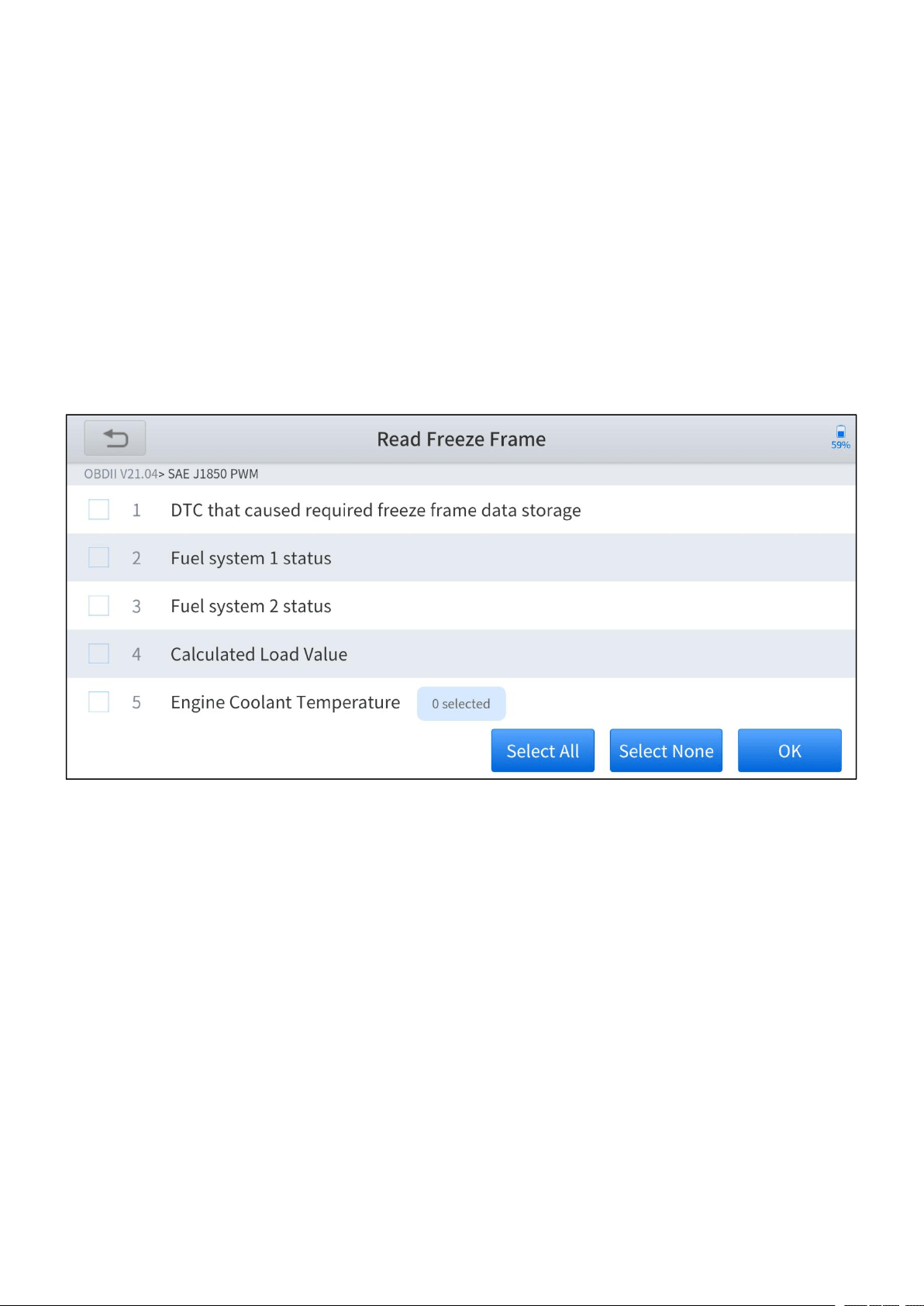
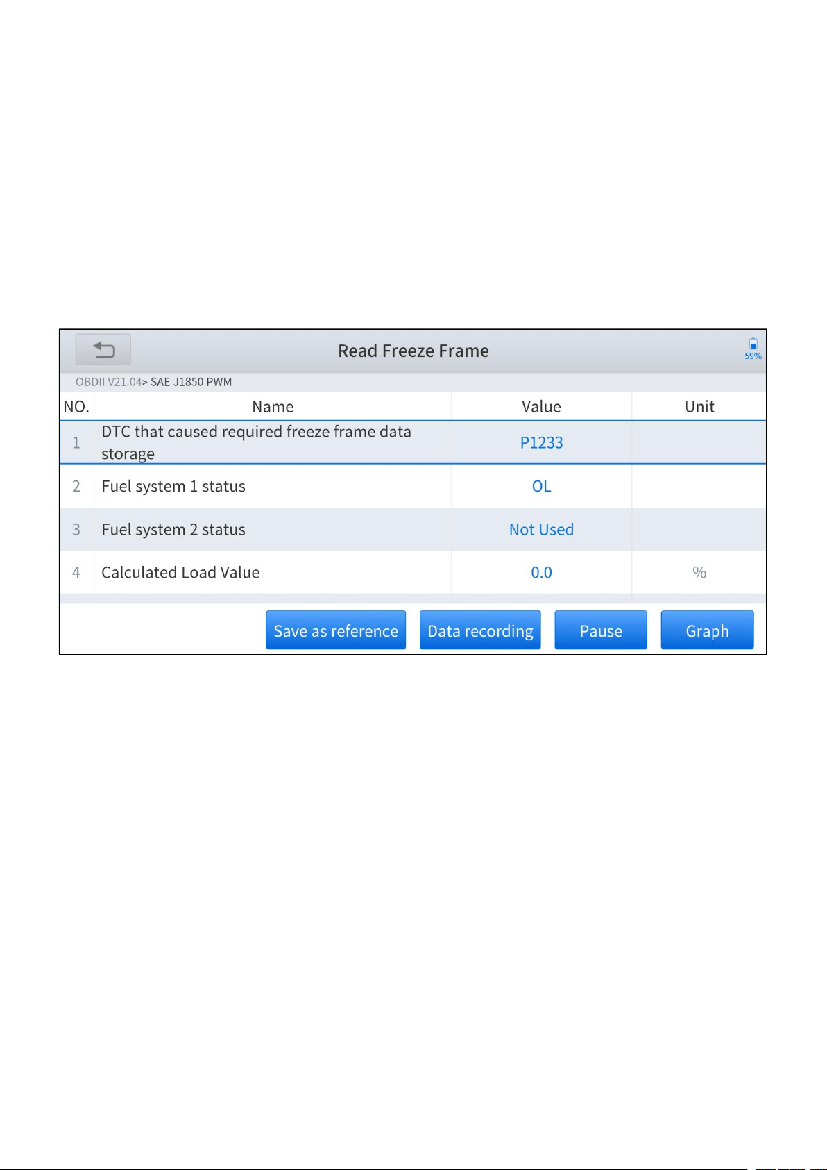
Read Freeze Frame
In most cases, the stored frame is the last DTC that occurred. Certain DTCs, which
have a greater impact on vehicle emission, have a higher priority. In these cases,
the freeze frame will record the top prioritized DTC. Freeze frame provides a
snapshot of critical parameters at the moment DTC is set.
This function is not supported by all models, and the option of freeze frame is not
available in these cases. Also, data recorded varies across brands and models.
Figure 3-11 Sample of freeze frame screen
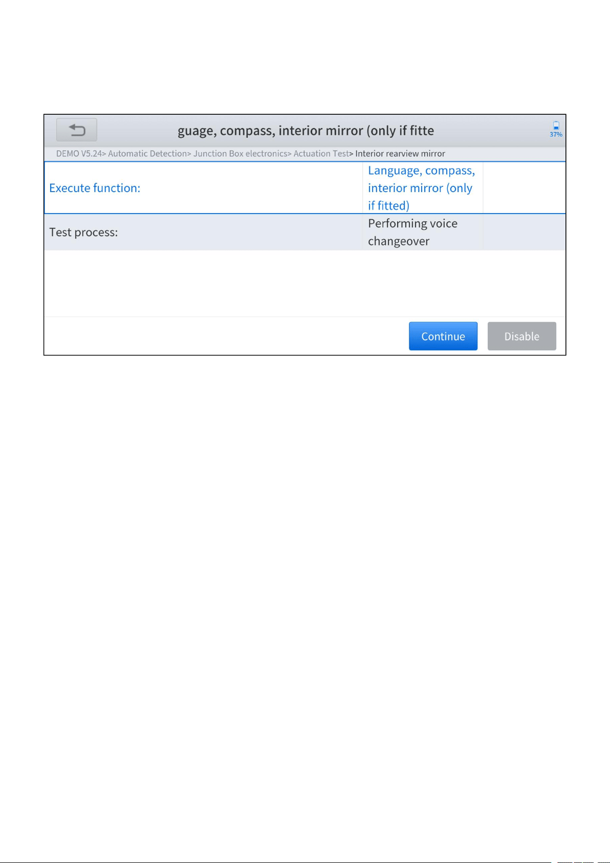
Actuation Test
Actuation test, also known as bidirectional control, is a generic term used to
describe sending and receiving information between one device and another. The
scan tool can request information or command a module to perform specific tests
or functions. Some manufacturers refer to the bidirectional controls as function
tests, actuation tests, inspection tests, system tests. Reinitialization and
reprogramming would also be included in the list of bidirectional controls. Most
enhanced scan tools also can actuate relays, injectors, and coils, perform system
—
20
—
tests, etc. Users could check the individual part to see which part is working
properly by actuation test.
Figure 3-12 Sample of actuation test screen
—
21
—
4 OBD II
You can perform the OBDII diagnosis by clicking the OBDII button after
entering the diagnosis menu.
Figure 4-1 Sample of diagnosis menu screen
The OBDII (On-board diagnostics) refers to the vehicle’s self-diagnostic and
reporting ability. When the malfunction of any sub-systems is detected, relevant
MIL is illuminated and notice the vehicle owner or repair technician the status of the
vehicle. OBDII implements the standardized digital communications port and
diagnostic trouble codes (DTCs) which allows scan tools to communicate with the
PCM of the vehicle. And the Anyscan is able to access the OBDII diagnostic
functions as follows:
Read & Clear Trouble Codes
Live Data
Read Freeze Frame
Read ECU Information
Component Test

—
22
—
On-Board Monitor Test
O2 Sensor Monitoring Test
I/M Readiness

—
23
—
Read Trouble Code
Read trouble codes (DTCs) that are stored in ECU. For the trouble code, the
diagnostic tool will give specific detailed definitions and explanations to help you
locate and eliminate the car fault.
Stored Code
Stored codes are the current emission-related DTCs from the ECM of the
vehicle. OBDII Codes have a priority according to their emission severity, with
higher priority codes overwriting lower priority codes. The priority of the code
determines the illumination of the MIL and the codes erase procedure.
Manufacturers rank codes differently, so expect to see differences between
makes.
Pending Code
These are codes whose setting conditions were met during the last drive cycle,
but need to be met two or more consecutive drive cycles before the DTC
actually sets. The intended use of this service is to assist the service
technician after a vehicle repair and after clearing diagnostic information, by
reporting test results after a driving cycle.
c. If a test failed during the driving cycle, the DTC associated with that test
is reported. If the pending fault codes do not occur again within 40 to 80
warm-up cycles, the fault is automatically cleared from memory.
d. Test results reported by this service do not necessarily indicate a faulty
component or system. If test results indicate another failure after
additional driving, then a DTC is set to indicate a faulty component or
system, and the MIL is illuminated.
—
24
—
Figure 4-2 Sample of read trouble code screen
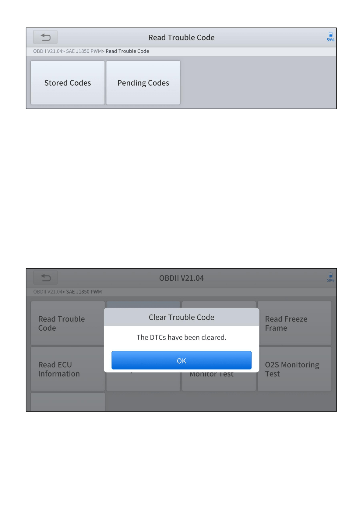
Clear Trouble Code
This option is used to clear all emission related diagnostic data such as DTCs,
freeze frame data, and manufacturer specific enhanced data from the vehicle’s
PCM. A confirmation screen displays when the clear codes option is selected to
prevent accidental loss of data. Select Yes on the confirmation screen to continue
or No to exit.
Figure 4-3 Sample of clear trouble code screen
—
25
—
Live Data
This function displays the real-time PID data from ECU. Displayed data includes
analog inputs and outputs, digital inputs and outputs, and system status
information broadcast on the vehicle data stream. Live data can be displayed in
various modes.
Figure 4-4 Sample of live data screen (table)
Figure 4-5 Sample of live data screen (graph)
—
26
—
Freeze Frame
In most cases, the stored frame is the last DTC that occurred. Certain DTCs, which
have a greater impact on vehicle emission, have a higher priority. In these cases,
the top prioritized DTC is the one for which the freeze frame records are retained.
Freeze frame data includes a “snapshot” of critical parameter values at the time
the DTC is set.
Figure 4-6 Sample of freeze frame screen
—
27
—
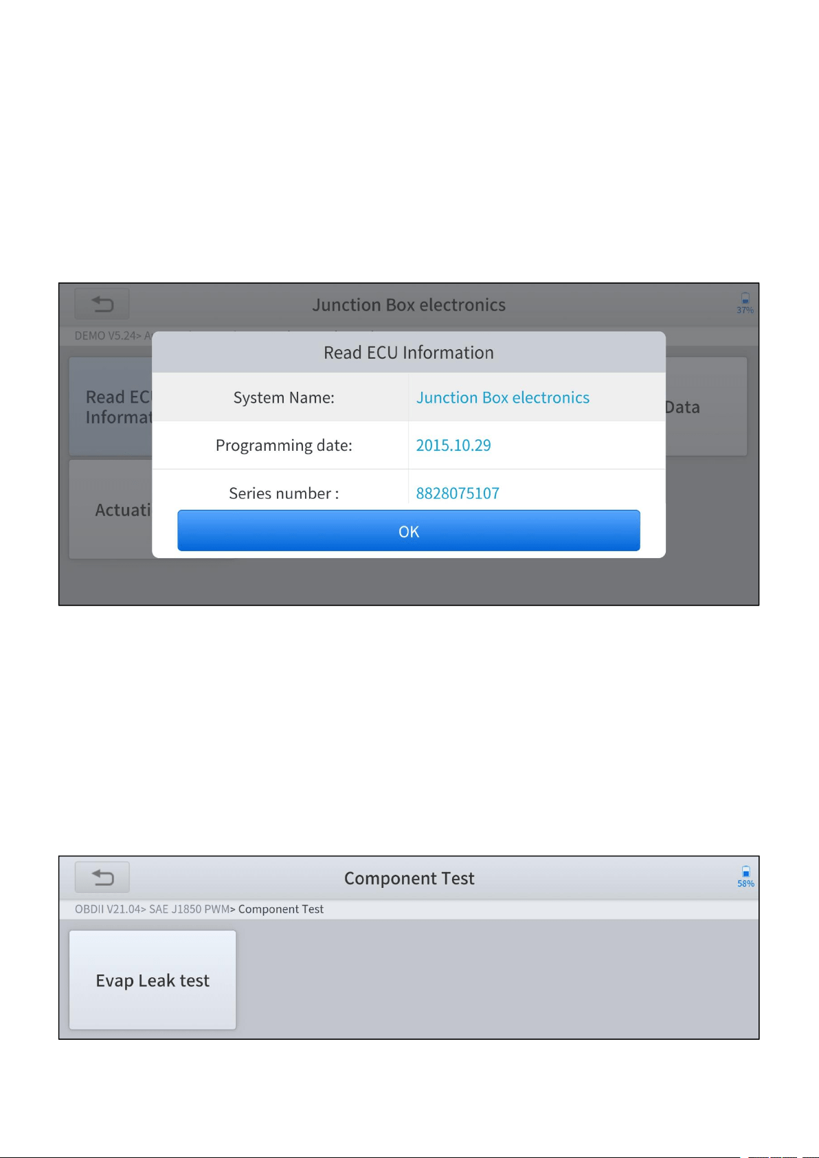
Read ECU Information
The option displays the vehicle identification number (VIN), the calibration
identification, and the calibration verification number (CVN), and other information
of the test vehicle.
Figure 4-7 Sample of read ECU information screen
Component Test
This service enables bi-directional control of the ECM so that the diagnostic tool is
able to transmit control commands to operate the vehicle systems. This function is
useful in determining whether the ECM responds to command well.
Figure 4-8 Sample of component test screen
—
28
—
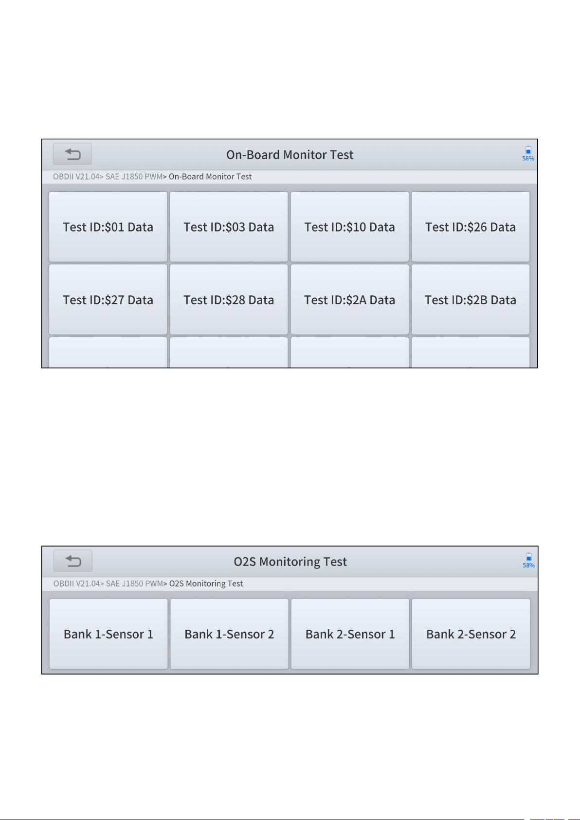
On-Board Monitoring Test
This option allows you to view the results of On-Board Monitor tests. The tests are
useful after servicing or after erasing a vehicle’s control module memory.
Figure 4-9 Sample of on-board monitor screen
O2 Sensor Monitoring Test
The oxygen sensor monitor allows the PCM to verify that the O2 sensors are
properly calibrated and functioning without noticeable deterioration under normal
engine operating conditions.
Figure 4-10 Sample of O2 Sensor monitoring test screen
—
29
—
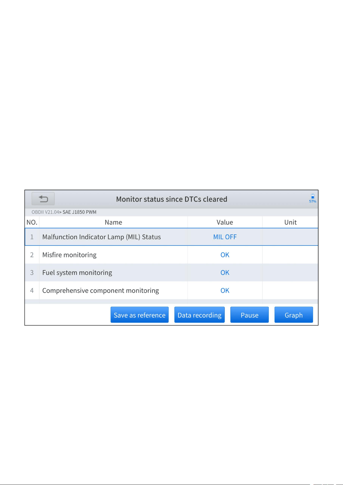
I/M Readiness
This function is used to check the readiness of the monitoring system. It is an
excellent function to use prior to having a vehicle inspected for compliance with a
state emissions program. Selecting I/M Readiness opens a submenu with two
choices:
Since DTCs Cleared – displays the status of monitors since the last time
the DTCs are erased.
This Driving Cycle – displays the status of monitors since the beginning
of the current drive cycle.
Figure 4-11 Sample of I/M readiness screen

—
30
—
5 SPECIAL FUNCTIONS
Special functions supported by Anyscan are various from models, table below
shows all the special functions supported by A30, A30D, A30M respectively.
Special Functions
A30
A30D
A30M
1
Oil Reset
✓
✓
✓
2
EPB
✓
✓
✓
3
SAS
✓
✓
✓
4
DPF
✓
✓
✓
5
Throttle
✓
✓
6
BMS Reset
✓
✓
7
TPMS Reset
✓
✓
8
ABS Bleeding
✓
✓
9
Injector Coding
✓
✓
10
Gearbox Match
✓
✓
11
Airbag Reset
✓
✓
12
Gear Learning
✓
✓
13
Suspension
✓
14
Windows Initialization
✓
15
Seat Match
✓
16
Headlight
✓
17
Instrument Cluster
✓
18
Transport Mode
✓
19
Tire Upgrade
✓
20
Power Balance
✓
21
Electronic Pump Activation
✓
Figure 5-1 Table of special functions
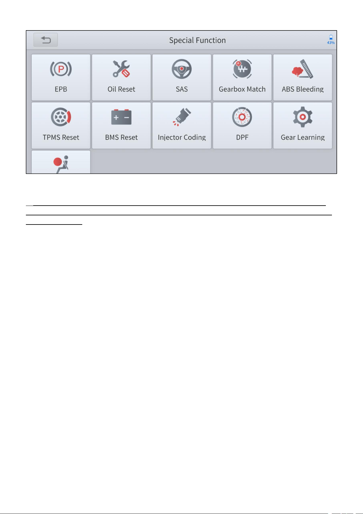
Special functions allow you to quickly access your vehicle system for various
scheduled services, maintenance and reset performance, eliminating the need to
reset after resolving common problems. This user manual lists some commonly
used special reset services for your reference. The special function interface is
shown as below:
—
31
—
Figure 5-1 Sample of special function screen (A30D)
All software screens shown in this manual are examples, actual test screens may vary for
each vehicle being tested. Observe the menu titles and on-screen instructions to make correct
option selections.
5.1 OIL RESET
Reset the Engine Oil Life System, which calculates the optimum oil life change
interval based on the vehicle’s driving conditions and climate. The oil life reminder
must be reset each time the oil is changed so that the system can calculate when
the next oil change is required.
This function can be performed in the following cases:
If the service lamp is on, you must provide service for the car. After service, you
need to reset the driving mileage or driving time so that the service lamp turns
off and the system enables the new service cycle.
After changing engine oil or electric appliances that monitor oil life, you need to
reset the service lamp.
—
32
—
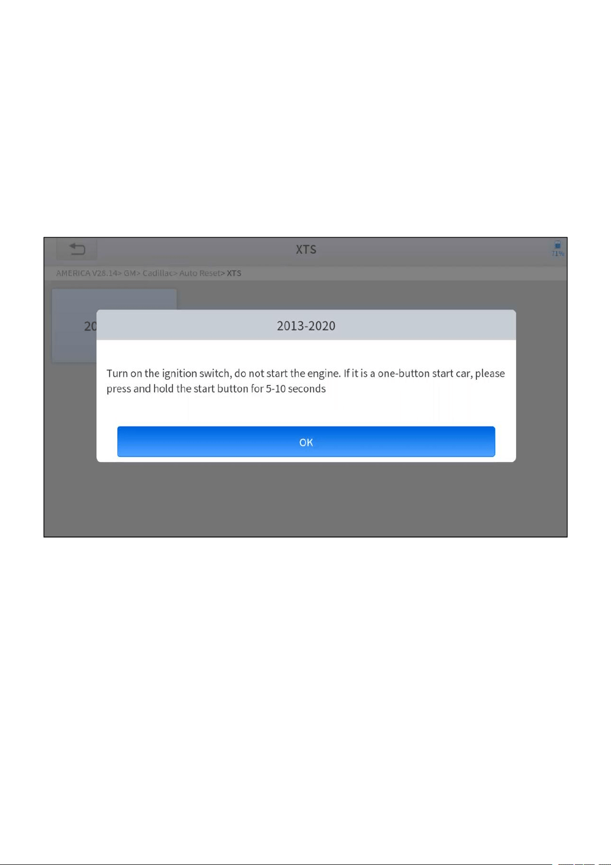
The operation guidelines of the Oil Reset function are shown as below:
1. Enter the Oil Reset menu and choose relevant models according to the vehicle
being tested.
2. Follow the instructions displayed and press OK after completing the
instructions shown.
Figure 5-2 Sample of oil reset function (screen 1)
3. Enter Maintenance mileage reset menu.

—
33
—
4. Input reasonable value of mileage and press OK.
Figure 5-3 Sample of oil reset function (screen 2)
5. Message of ‘Reset success’ displayed when Oil Reset function has
successfully performed.

—
34
—
5.2 EPB
Electronic Parking Brake (EPB) System reset is a popular special function. You can
use this function to reset the electronic parking brake system and brake pads,
which also supports the brake pad replacement (retraction, release of the brake
pump), G-sensor, and body angle calibration. This function has multiple uses and
can safely and effectively maintain the electronic brake system. These applications
include deactivating and activating brake control systems, assisting in controlling
brake fluid, opening and closing brake pads, and setting brakes after replacing
brake discs or brake pads, etc.
1. If the brake pad wears the brake pad sense line, the brake pad sense line will
send a signal to the onboard tablet asking for replacing the brake pad. After
replacing the brake pad, you must reset the brake pad. Otherwise, the car
alarms.
2. Reset must be performed in the following cases:
The brake pad and brake pad wear sensor are replaced.
The brake pad indicator lamp is on.
The brake pad sensor circuit is short, which is recovered.
The servo motor is replaced.
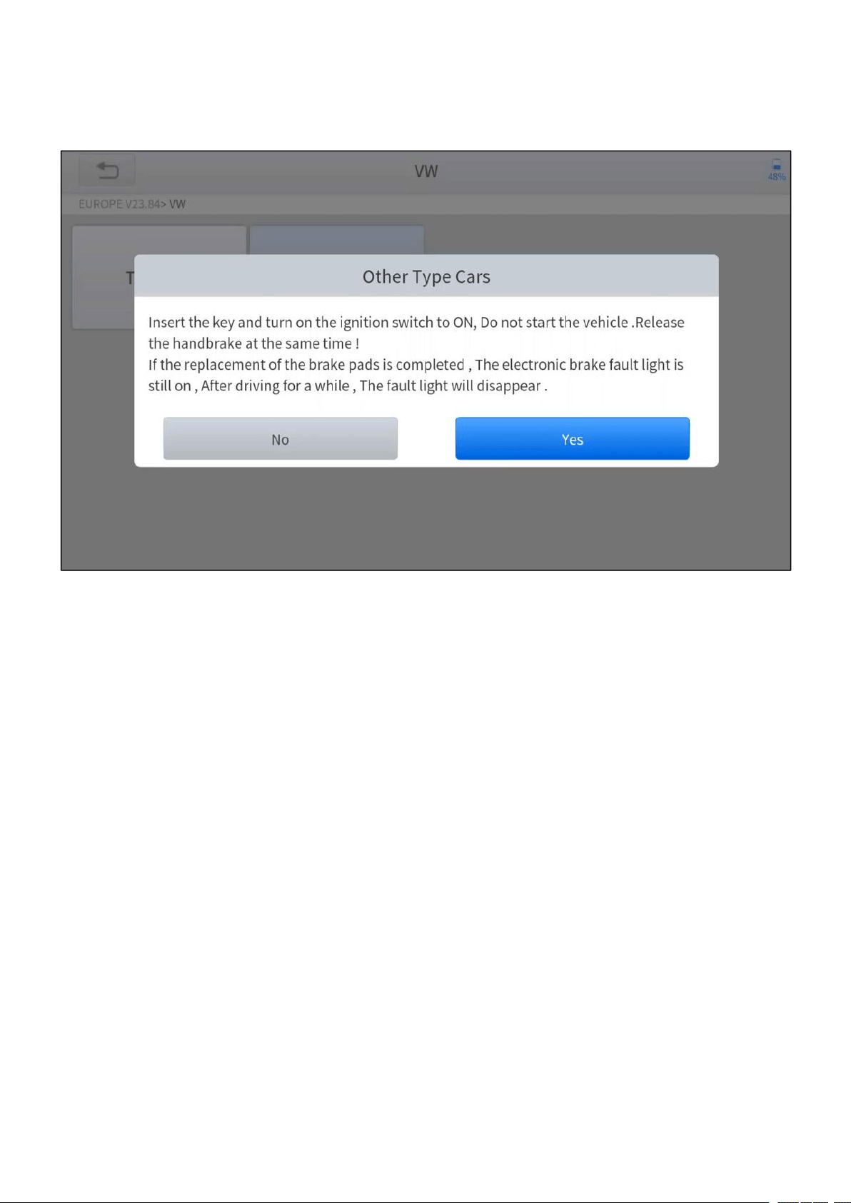
The operation guidelines of the EPB function are shown as below:
1. Enter the EPB menu and choose relevant models according to the vehicle
being tested.
—
35
—
2. Follow the instructions displayed and press YES after completing the
instructions shown.
Figure 5-4 Sample of EPB function (screen 1)
—
36
—
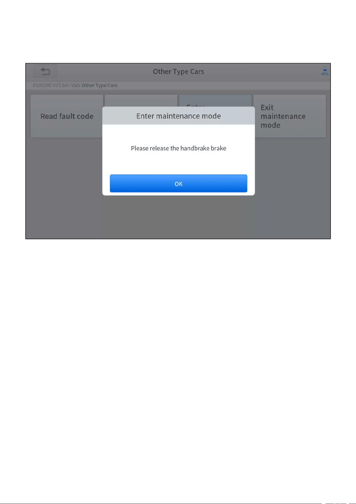
3. Enter the Enter maintenance mode menu and release the handbrake brake.
And press OK after completing the instructions shown.
Figure 5-5 Sample of EPB function (screen 2)
4. Wait until the message of ‘Successful operation’ popes up. And press OK to
exit the menu.
5. Enter the Exit maintenance mode menu and wait until the message of
‘‘Successful operation’ popes up.

—
37
—
5.3 SAS
Steering Angle Sensors (SAS) System Calibration permanently stores the current
steering wheel position as the straight-ahead position in the SAS EEPROM.
Therefore, the front wheels and the steering wheel must be set exactly to the
straight-ahead position before calibration. In addition, the VIN is also read from the
instrument cluster and stored permanently in the SAS EEPROM. On successful
completion of calibration, the SAS fault codes will be automatically cleared.
To reset the steering angle, you need to first find the relative zero point position for
the car to drive in a straight line. Taking this position as a reference, the ECU can
calculate the accurate angle for left and right steering.
After replacing the steering angle position sensor, replacing steering mechanical
parts (such as steering gearbox, steering column, end tie rod, steering knuckle),
performing four-wheel alignment, or recovering the car body, you must reset the
steering angle.
The operation guidelines of the SAS function are shown as below:
1. Enter the SAS menu and choose relevant models according to the vehicle
being tested.
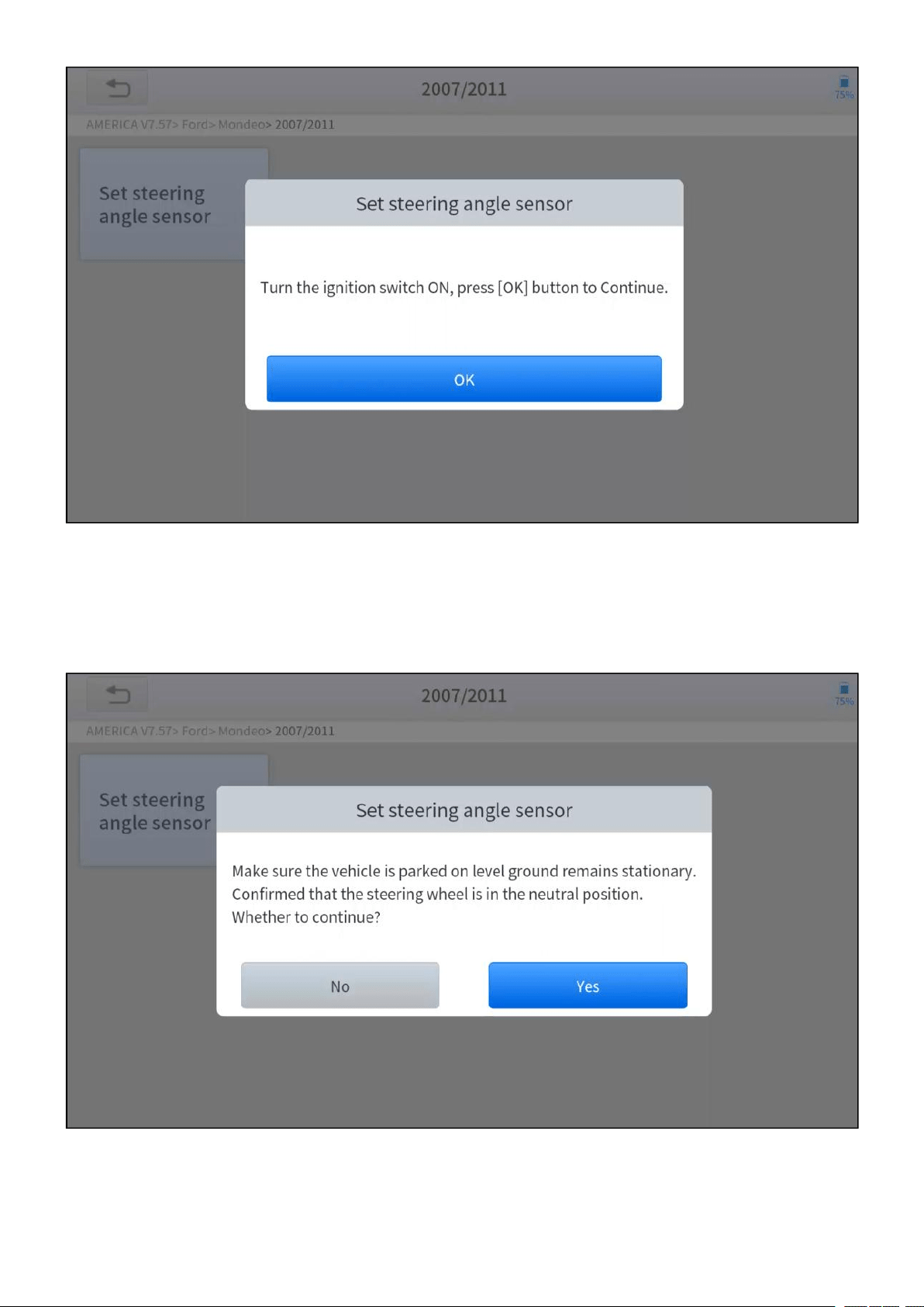
2. Enter the Set steering angle sensor menu and follow the instructions
displayed.
—
38
—
Figure 5-6 Sample of SAS function (screen 1)
3. Wait until the following instruction displayed and press Yes after completing the
instructions shown.
Figure 5-7 Sample of SAS function (screen 2)
—
39
—
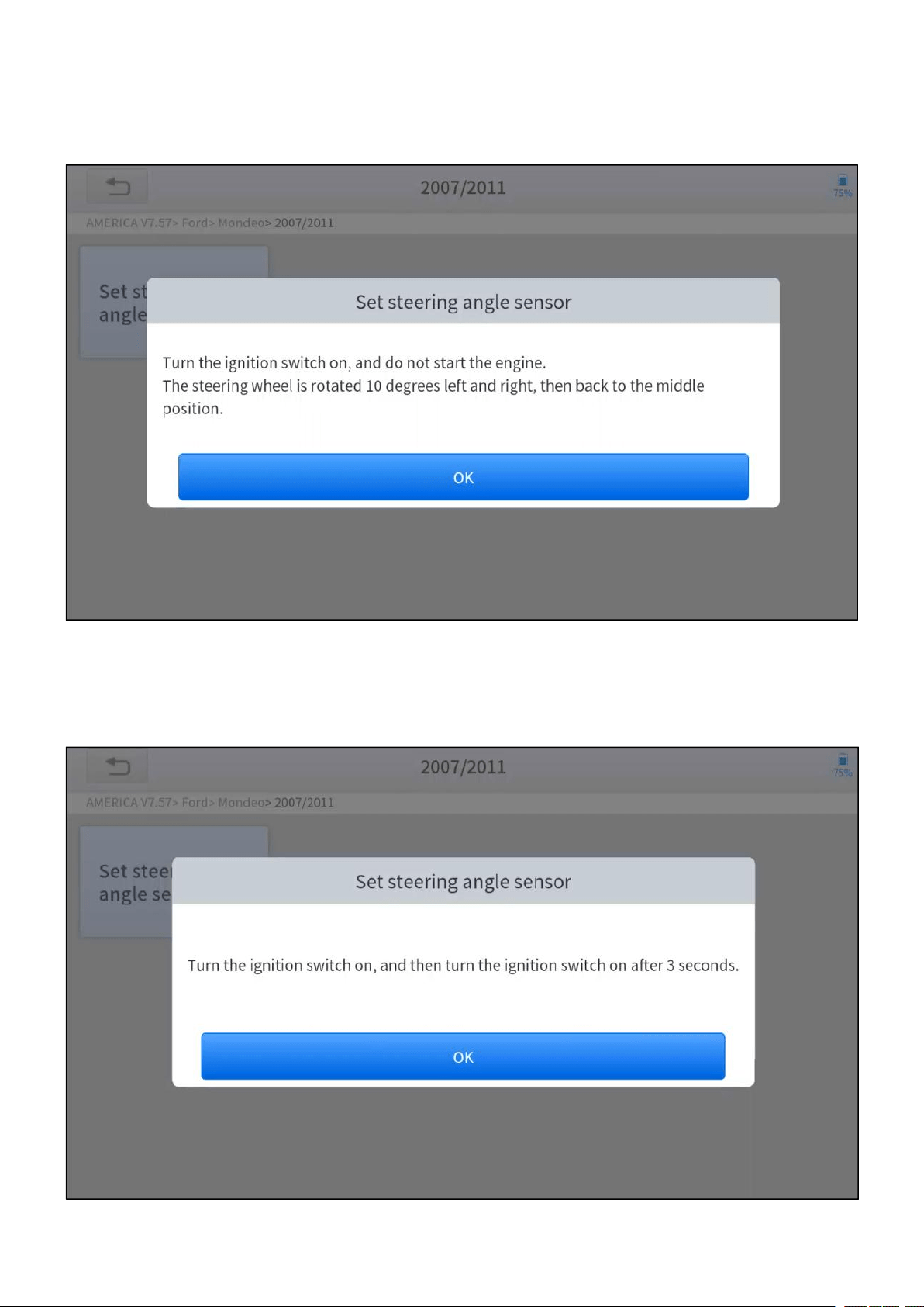
4. Follow the instructions displayed and press OK after completing the
instructions shown.
Figure 5-8 Sample of SAS function (screen 3)
5. Wait until the following instruction displayed and press OK after completing the
instructions shown.
Figure 5-9 Sample of SAS function (screen 4)

—
40
—
6. Message of ‘Function execution is completed’ displayed when SAS
function has successfully performed.

—
41
—
5.4 DPF
The Diesel Particle Filter (DPF) function manages DPF regeneration, DPF
component replacement teach-in, and DPF teach-in after replacing the engine
control module (ECM).
The ECM monitors driving style and selects a suitable time to employ regeneration.
Vehicles driven a lot at idling speed and low load will attempt to regenerate earlier
than vehicles driven more with higher load and speed. For regeneration to take
place, a prolonged high exhaust temperature must be obtained.
In the event of the car being driven in such ways that regeneration is not possible,
i.e., frequent short journeys, a diagnostic trouble code will eventually be registered
in addition to the DPF light and “Check Engine” indicators displaying. A service
regeneration can be requested in the workshop using the diagnostic tool.
DPF regeneration is used to clear PM (Particulate Matter) from the DPF filter
through continuous combustion oxidation mode (such as high-temperature heating
combustion, fuel additive or catalyst reduce PM ignition combustion) to stabilize
the filter performance.
DPF regeneration may be performed in the following cases:
The exhaust back pressure sensor is replaced.
The PM trap is removed or replaced.
The fuel additive nozzle is removed or replaced.
The catalytic oxidizer is removed or replaced.
The DPF regeneration MIL is on and maintenance is performed.
The DPF regeneration control module is replaced.
—
42
—
The operation guidelines of the DPF function are shown as below:
1. Enter the DPF menu and choose relevant models according to the vehicle
being tested.
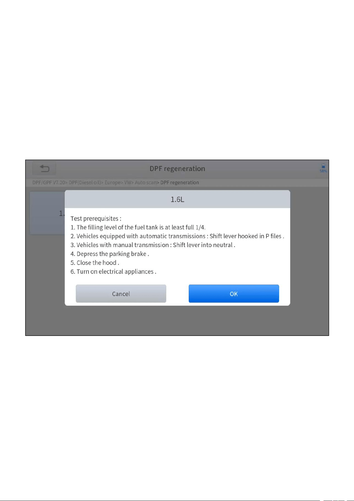
2. Enter the DPF regeneration menu.
3. Read carefully and complete the requisites listed before performing the DPF
regeneration function. And press OK after completing the instructions shown.
Figure 5-10 Sample of DPF function (screen 1)
4. Read the fuel tank level and make sure that it fulfills the requirement displayed.
5. Read the carbon deposit load.
—
43
—
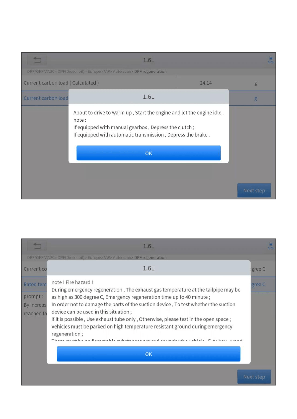
6. Choose drive to warm up and follow the instructions listed below. And press OK
after completing the instructions shown.
Figure 5-11 Sample of DPF function (screen 2)
7. Read the note carefully and follow the instructions shown on the screen. And
press OK after completing the instructions shown.
Figure 5-12 Sample of DPF function (screen 3)
—
44
—
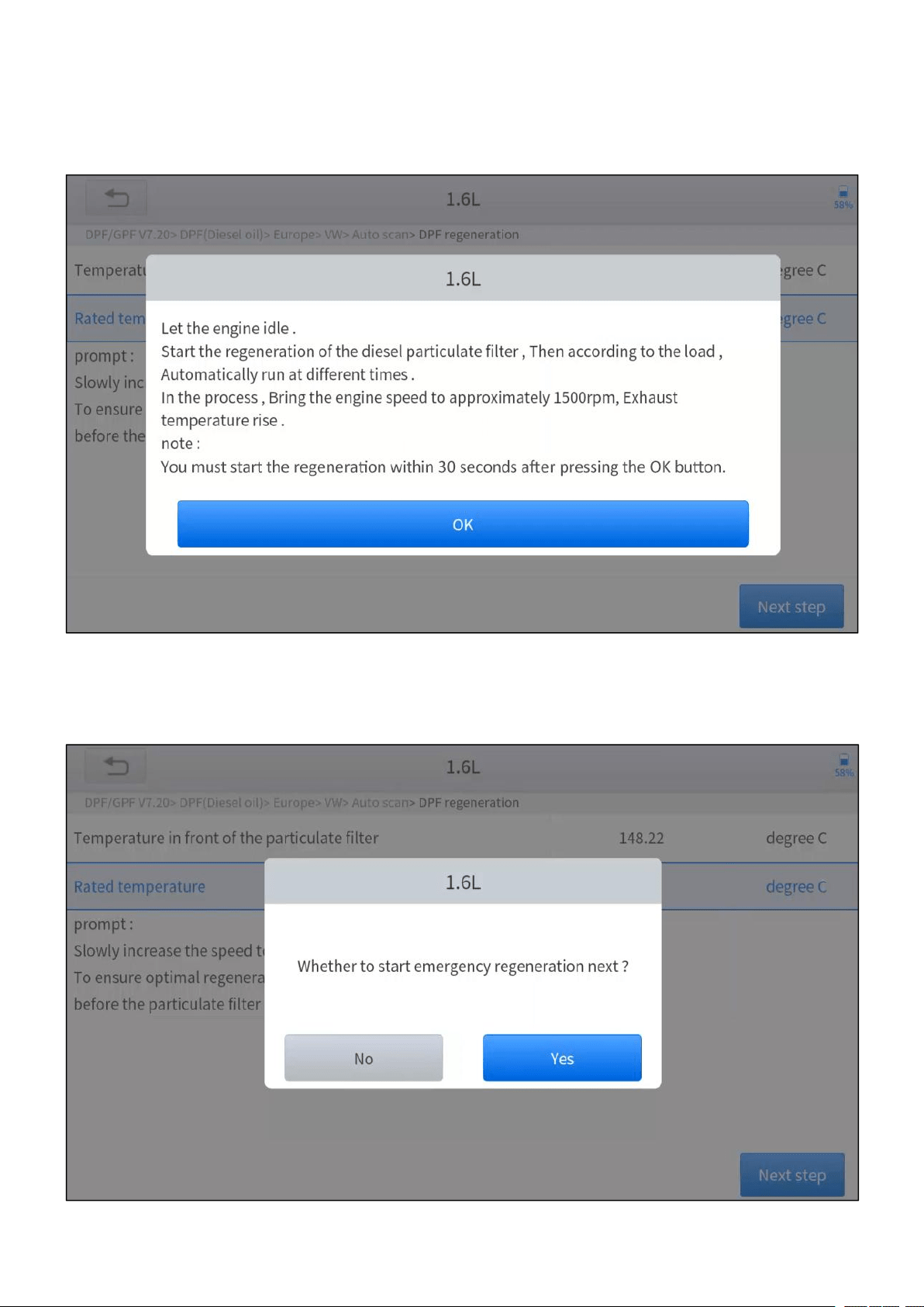
8. Follow the instructions displayed and press OK after completing the
instructions shown. Please pay attention to the Note.
Figure 5-13 Sample of DPF function (screen 4)
9. Press the OK button to start the regeneration.
Figure 5-14 Sample of DPF function (screen 5)
—
45
—
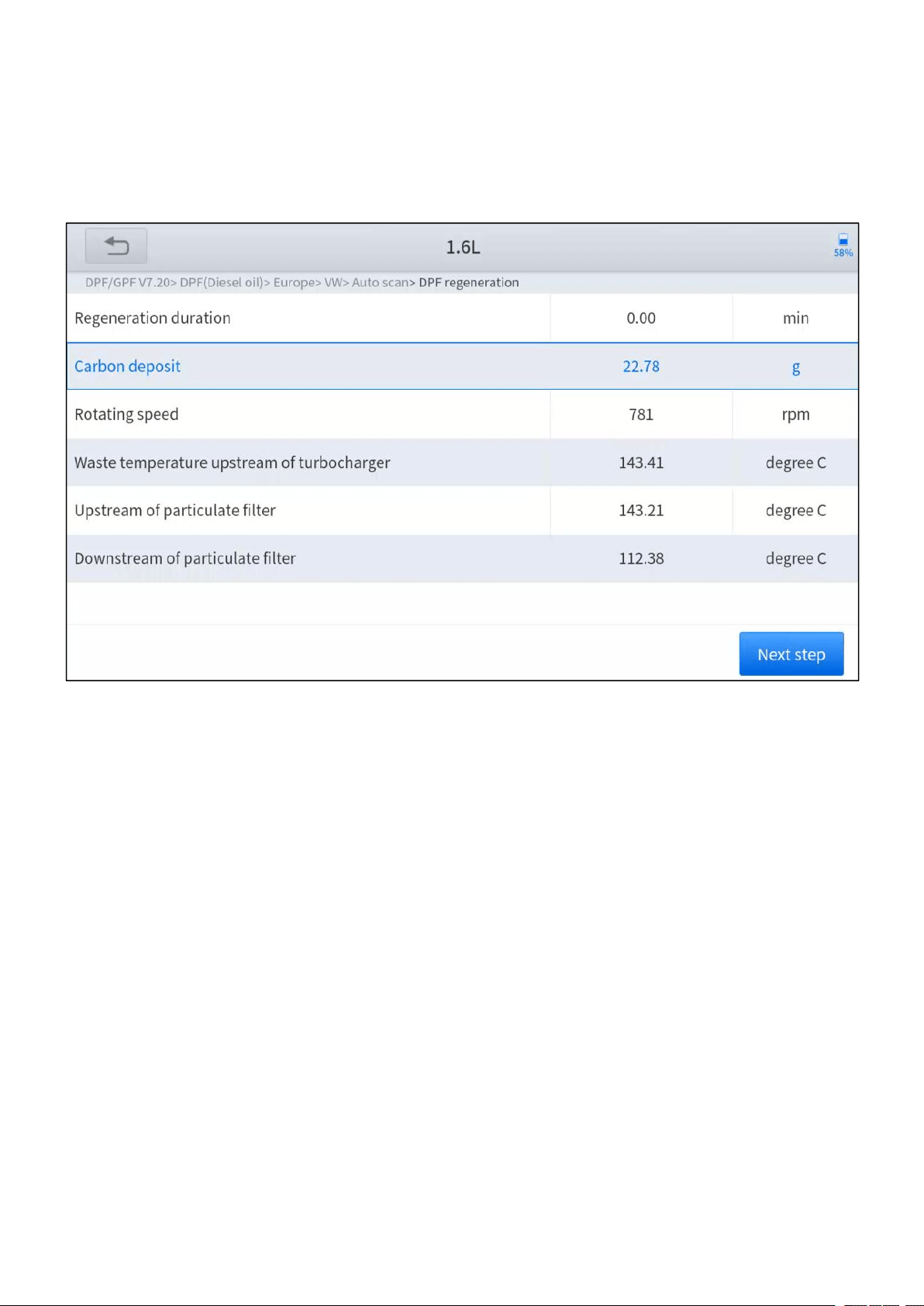
10.Wait for the value of carbon deposit to decrease until a message of ‘Emergency
regeneration has been successfully completed’ popes up, this process may
take up to 40 minutes.
Figure 5-15 Sample of DPF function (screen 5)
—
46
—
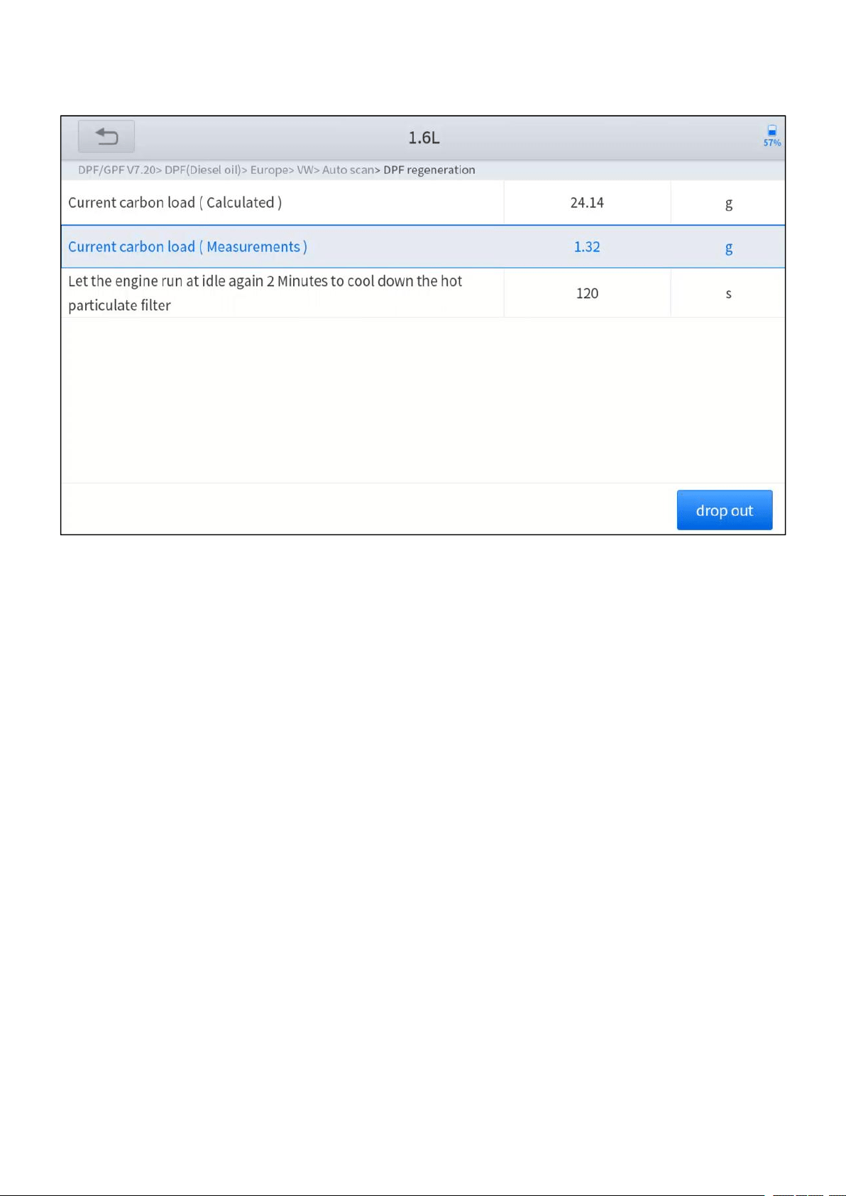
11. Wait for 2 minutes to let the particulate filter cool down.
Figure 5-16 Sample of DPF function (screen 6)
12.Press drop out to exit the DPF function.

—
47
—
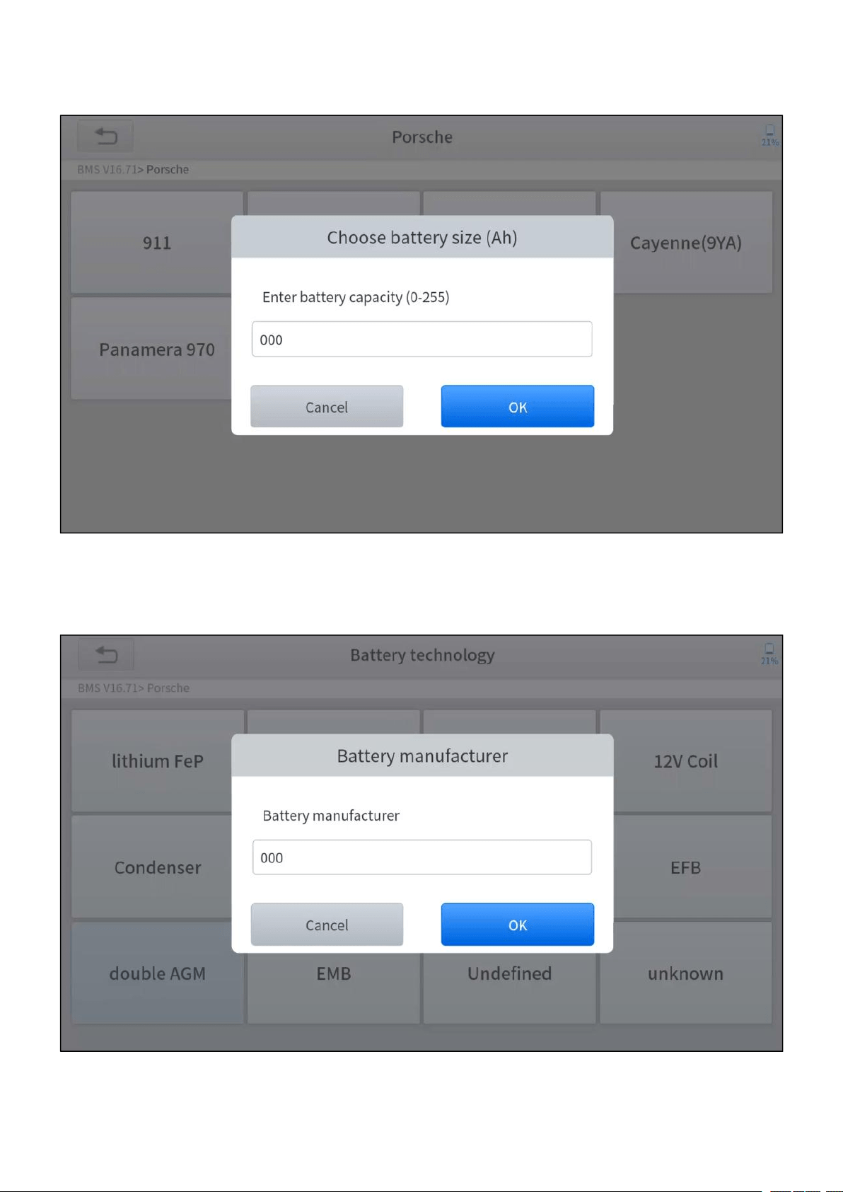
5.5 BMS RESET
The Battery Management System (BMS) allows the scan tool to evaluate the
battery charge state, monitor the close-circuit current, register the battery
replacement, and activate the rest state of the vehicle.
This function enables you to perform a resetting operation on the monitoring unit of
the vehicle battery, in which the original low battery fault information will be cleared
and battery matching will be done.
Battery matching must be performed in the following cases:
The main battery is replaced. Battery matching must be performed to clear
original low battery information and prevent the related control module from
detecting false information. If the related control module detects false
information, it will invalidate some electric auxiliary functions, such as automatic
start & stop function, sunroof without one-key trigger function, power window
without automatic function.
Battery matching is performed to re-match the control module and motoring
sensor to detect battery power usage more accurately, which can avoid an error
message displayed on the instrument cluster.
The operation guidelines of the BMS Reset function are shown as below:
1. Enter the BMS Reset menu and choose relevant models according to the
vehicle being tested.
2. Turn on the ignition switch.
3. Press OK to continue the BMS function.
—
48
—
4. Enter battery capacity (within the given range) and press OK after the input.
Figure 5-17 Sample of BMS function (screen 1)
5. Enter the battery manufacturer and press OK after the input.
Figure 5-18 Sample of BMS function (screen 2)
—
49
—
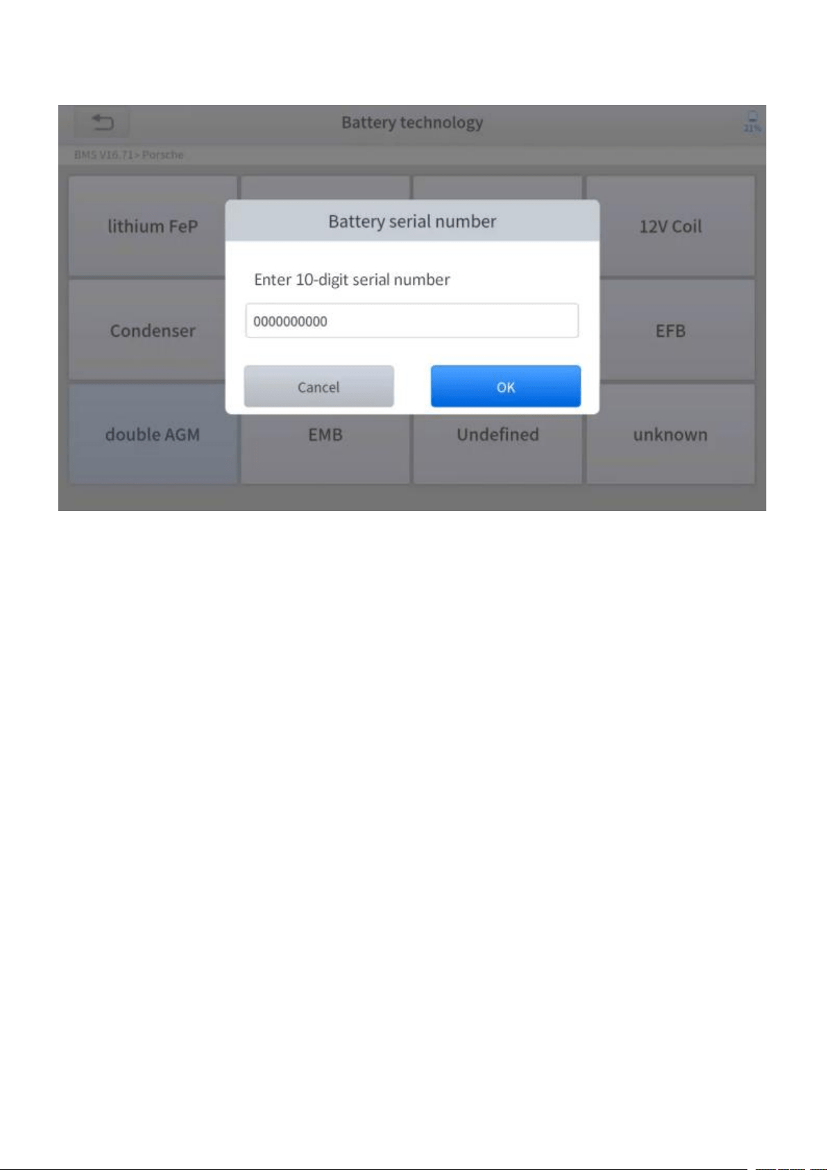
6. Enter the 10-digit battery serial number and press OK after the input.
Figure 5-19 Sample of BMS function (screen 3)
—
50
—
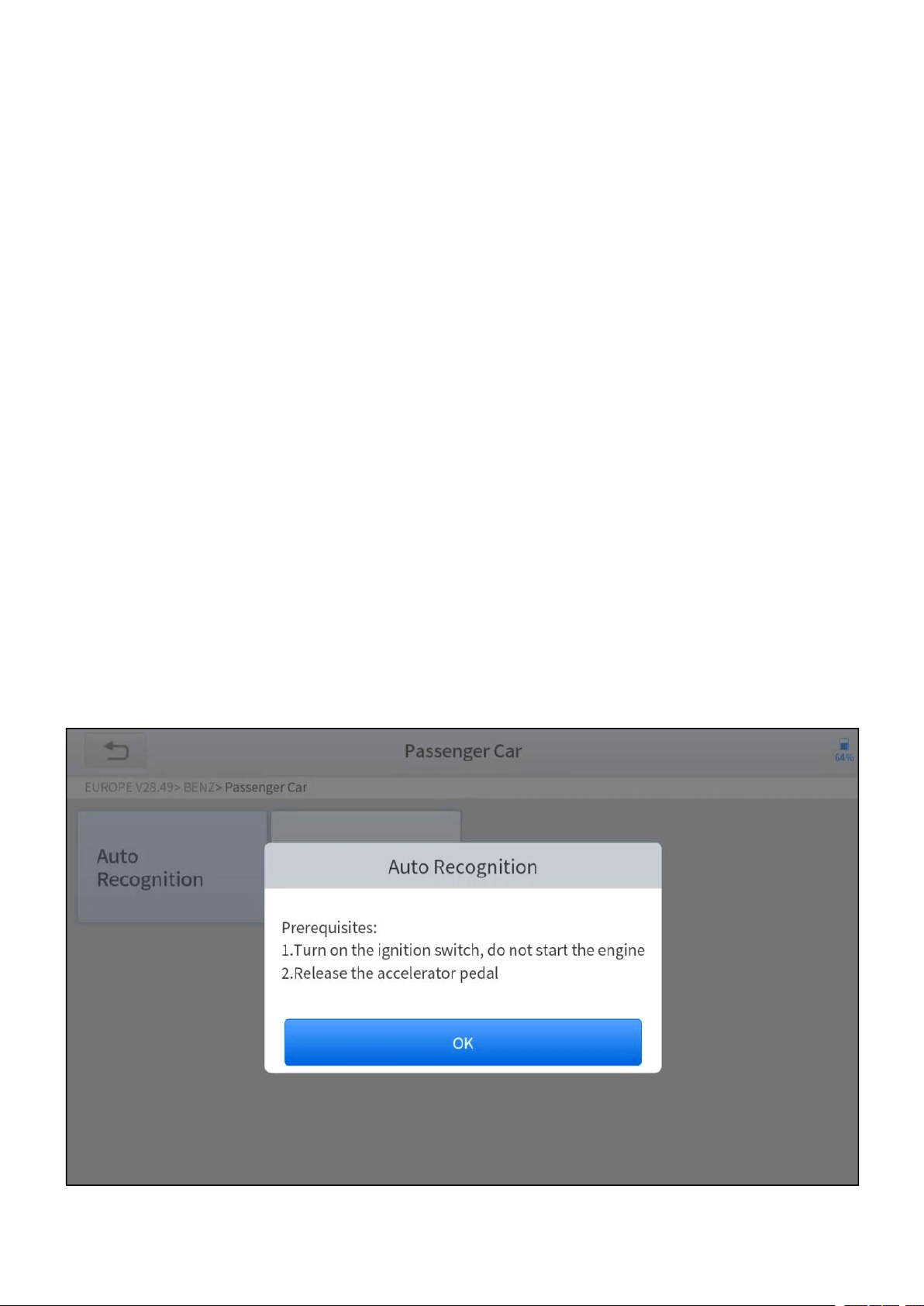
5.6 THROTTLE
Throttle Position Sensor (TPS) Match, this function enables you to make initial
settings to throttle actuators and returns the “learned” values stored on ECU to the
default state. Doing so can accurately control the actions of regulating throttle (or
idle engine) to adjust the amount of air intake.
The operation guidelines of the Throttle function are shown as below:
1. Enter the Throttle menu and choose relevant models according to the vehicle
being tested.
2. Enter the Auto Recognition menu and turn on the ignition switch.
3. Read carefully and complete the requisites listed before performing the throttle
regeneration function. And press OK after completing the instructions shown.
Figure 5-20 Sample of throttle function (screen 1)
—
51
—
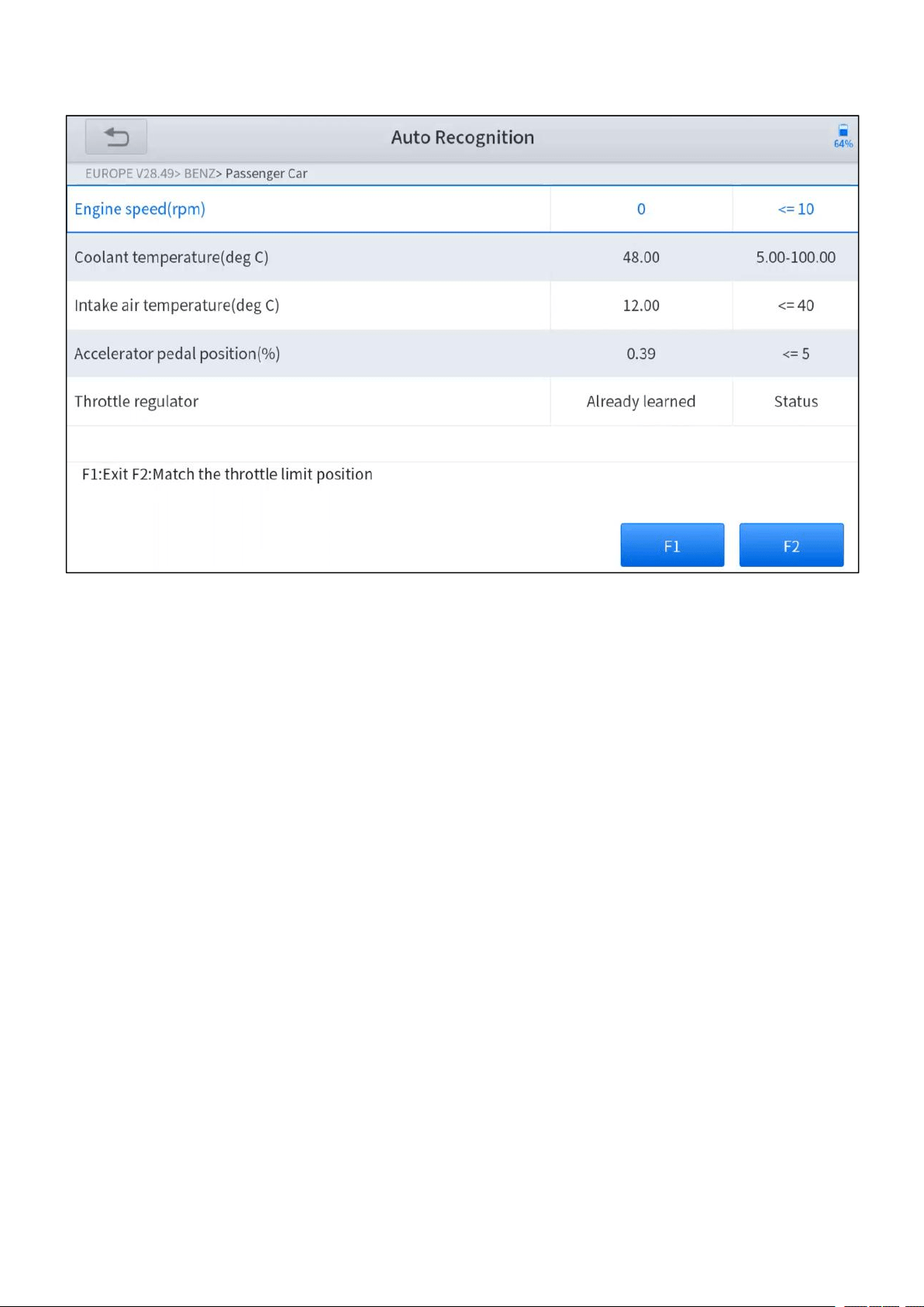
4. Wait until all the parameters are read and displayed.
Figure 5-21 Sample of throttle function (screen 2)
5. Press F2 button and wait until a message of ‘Match successfully’ popes up.

—
52
—
5.7 INJECTOR CODING
This function can write the identification code of the fuel injector into the ECU so
that the ECU can recognize and work normally. Write actual injector code or rewrite
code in the ECU to the injector code of the corresponding cylinder for controlling
accurately and correcting cylinder injection quantity.
After the ECU or injector is replaced, the injector code of each cylinder must be
confirmed or re-coded so that the cylinder can better identify injectors to accurately
control fuel injection.
In general cases, there is no need to do the coding matching function after cleaning.
The identification of the fuel injector includes its working accuracy value and type value. When
replacing it, you need to find the corresponding model for replacement.
At present, mainstream cars support injector coding function.
The operation guidelines of the Injector Coding function are shown as below:
1. Enter the Injector coding menu and choose relevant chassis models
according to the vehicle being tested.
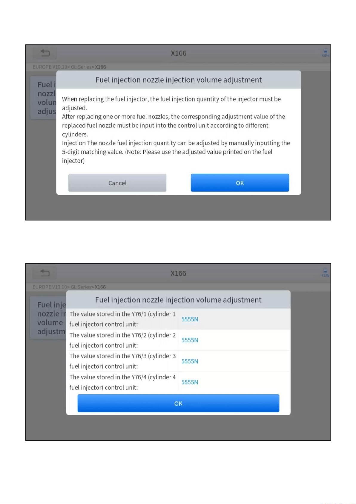
2. Enter the Fuel injection nozzle injection volume adjustment menu.
—
53
—
3. Read the note displayed carefully and press OK after the reading.
Figure 5-22 Sample of injector coding function (screen 1)
4. Read and confirm the value stored in the cylinders.
Figure 5-23 Sample of injector coding function (screen 2)

—
54
—
5. Enter the Change the value of cylinder menu of the replaced injector(s), and
enter the new 5-digit value and then press OK.
Figure 5-24 Sample of injector coding function (screen 3)
6. Wait until the message of ‘Write successfully’ popes up.
7. Turn off the ignition switch.
8. Wait until the message asked you to turn on the ignition switch.
—
55
—
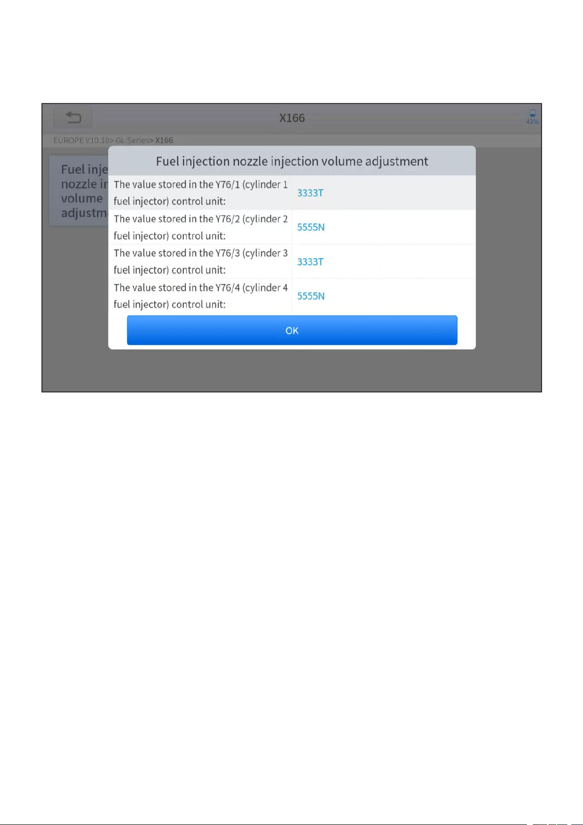
9. Re-enter the Fuel injection nozzle injection volume adjustment menu to
check whether the new value(s) are shown.
Figure 5-25 Sample of injector coding function (screen 4)
—
56
—
5.8 GEARBOX MATCH
After changing the gearbox or changing the gearbox ECU, you need to use the
gearbox matching function to re-match the engine and the gearbox.
Before resetting the gearbox, please check the gearbox control unit to ensure that there is no
fault code. If there is a fault code, the gearbox memory function cannot be reset. Please road test
after reset.
The operation guidelines of the Gearbox Matching function are shown as
below:
1. Enter the Gearbox matching menu and choose relevant models according to
the vehicle being tested.
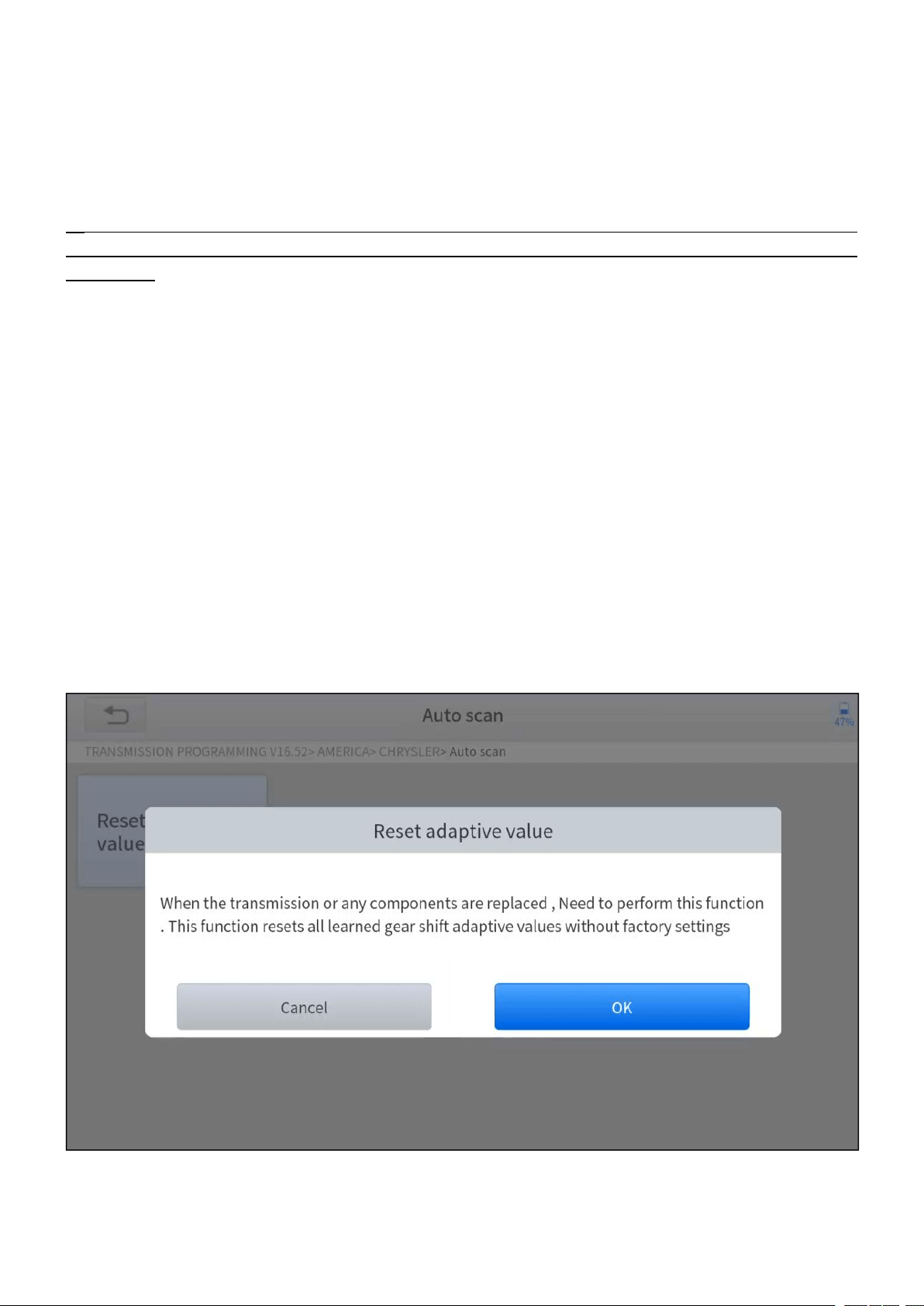
2. Enter the Reset adaptive value menu.
3. Turn on the ignition without starting the engine.
4. Read the note and press OK to continue the Gearbox Matching function.
Figure 5-26 Sample of gearbox matching function (screen 1)
5. Wait until the message ‘Successful operation’ popes up.

—
57
—
5.9 GEAR LEARNING
The crankshaft position sensor learns crankshaft tooth machining tolerance and
saves to the tablet to more accurately diagnose engine misfires. If gear learning is
not performed for a car equipped with a Delphi engine, the MIL turns on after the
engine is started. The diagnostic device detects the DTC P1336 'Gear not learned'.
In this case, you must use the diagnostic device to perform gear learning for the car.
After gear learning is successful, the MIL turns off. This function can complete the
self-learning of the gearbox and improve the quality of shifting.
After the engine ECU, crankshaft position sensor, or crankshaft flywheel is
replaced, or the DTC 'gear not learned' is present, gear learning must be
performed.
The operation guidelines of the Gear learning function are shown as below:
1. Enter the Gear learning menu and choose relevant models according to the
vehicle being tested.
2. Turn on the ignition switch to start the vehicle.
3. Enter the Tooth Learning menu.
—
58
—
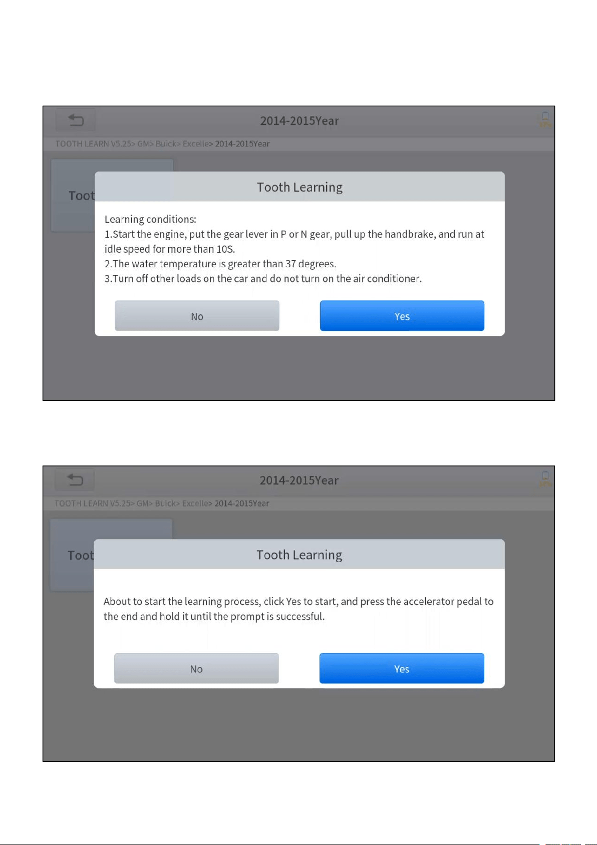
4. Read carefully and complete the requisites listed before performing the gear
learning function. And press OK after completing the instructions shown.
Figure 5-27 Sample of gear learning function (screen 1)
5. Read the instructions displayed and press Yes to start the learning process.
Figure 5-28 Sample of gear learning function (screen 2)

—
59
—
6. Press the accelerator pedal all the way down and hold it until a message of
‘The learning is successful, please release the accelerator pedal.’ popes up.
7. Release the accelerator pedal and press OK to exit the gear learning function.
—
60
—
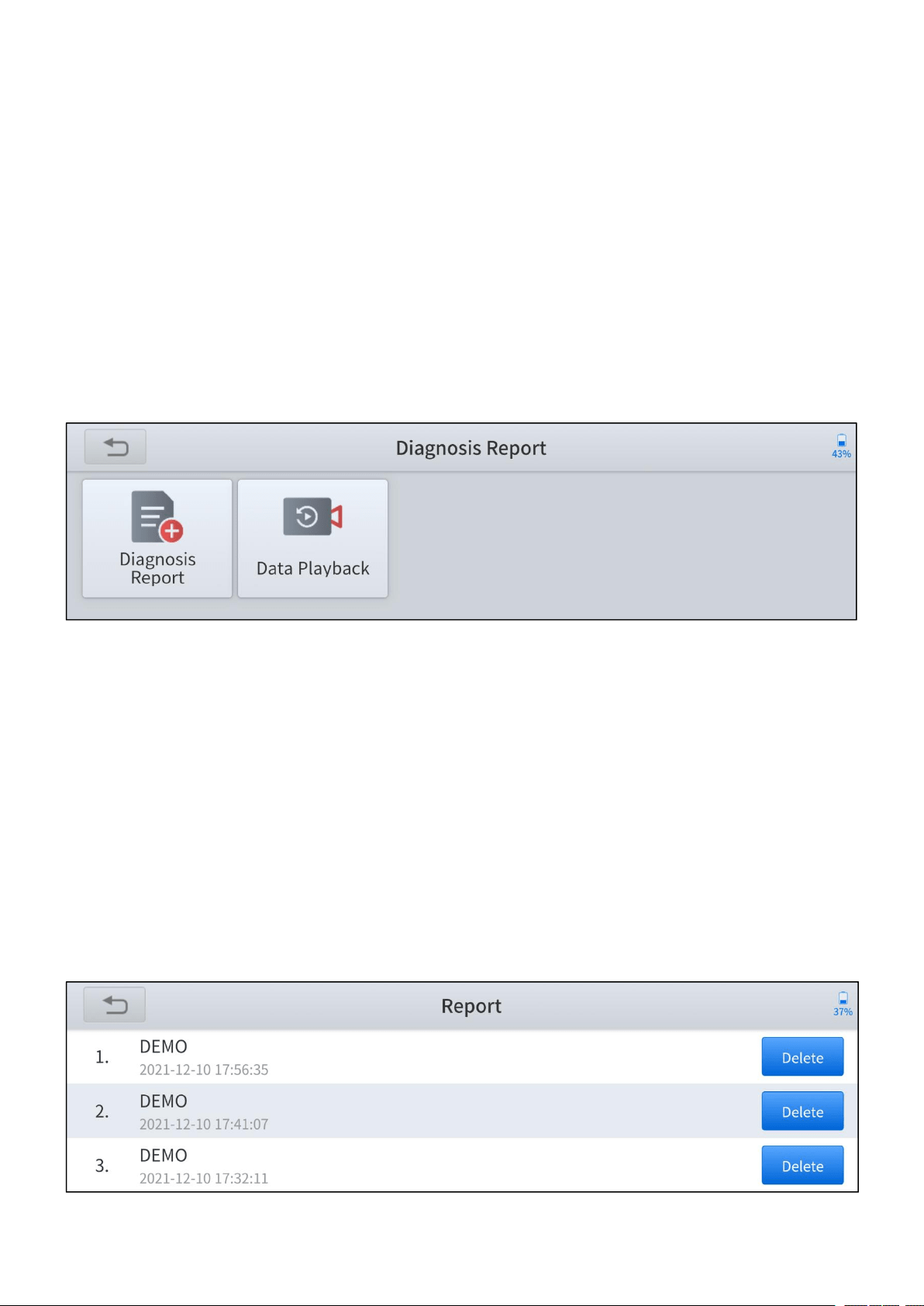
6 REPORTS
Diagnosis Reports are used for viewing and printing the saved files, such as Live
Data, Trouble Codes, or pictures generated in the process of diagnosis, users also
can view a record of which vehicles have been previously tested. It includes 2
parts:
Diagnosis Report
Data Playback
Figure 6-1 Sample of reports screen
6.1 DIAGNOSIS REPORT
Diagnosis reports will be automatically generated when the diagnosis is performed,
such as auto-diagnosis, read ECU information, read trouble codes, live data. And
all the reports generated can be found under the Diagnosis Report, you can view
and delete the reports according to your needs.
Figure 6-2 Diagnosis report list
—
61
—
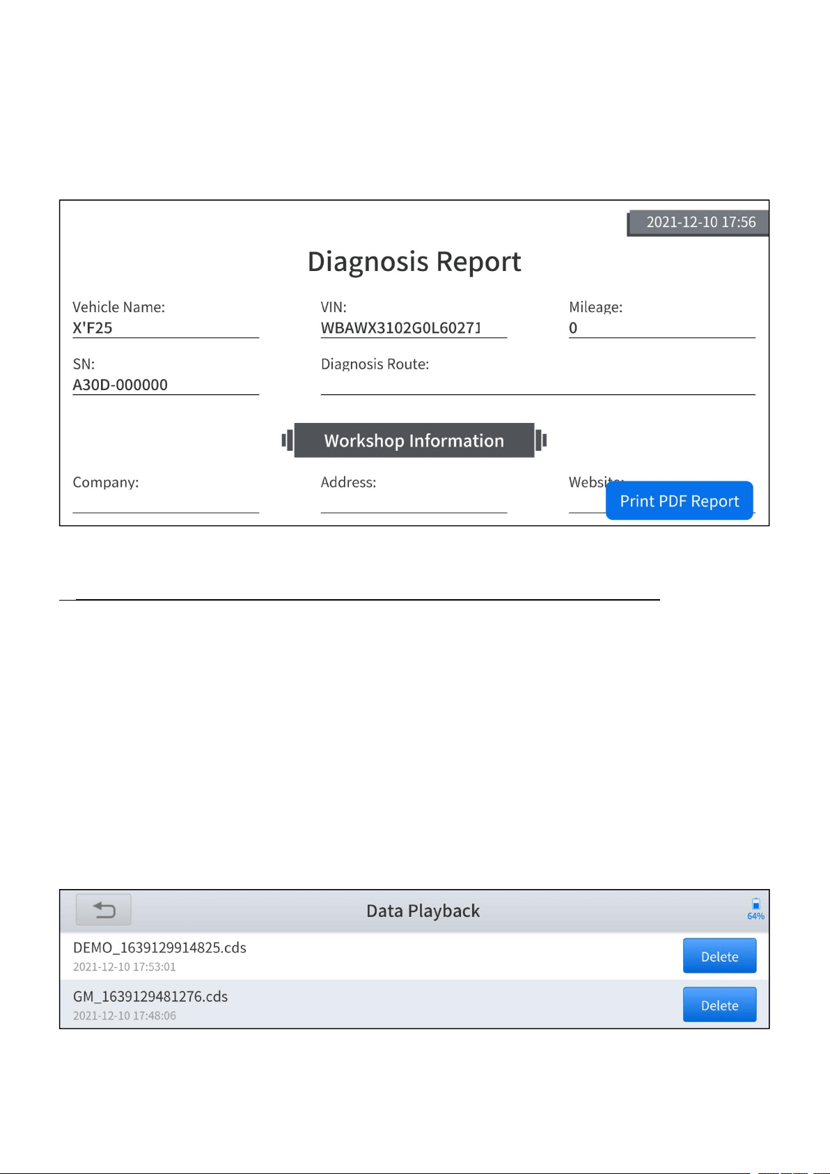
Press the Print PDF Report button to generate the PDF file and open it with the
installed app on your mobile device. You can easily view, share and print the
reports.
Figure 6-3 Sample of diagnosis report (PDF)
The detailed information of Workshop Information can be filled in in the Setting.
6.2 DATA PLAYBACK
This function allows you to replay the Live Data recorded during the diagnosis
process. The data will only be recorded when you have pressed the Data
Recording button and valid data were shown when performing the Live Data
function.
Figure 6-4 Data playback list
—
62
—
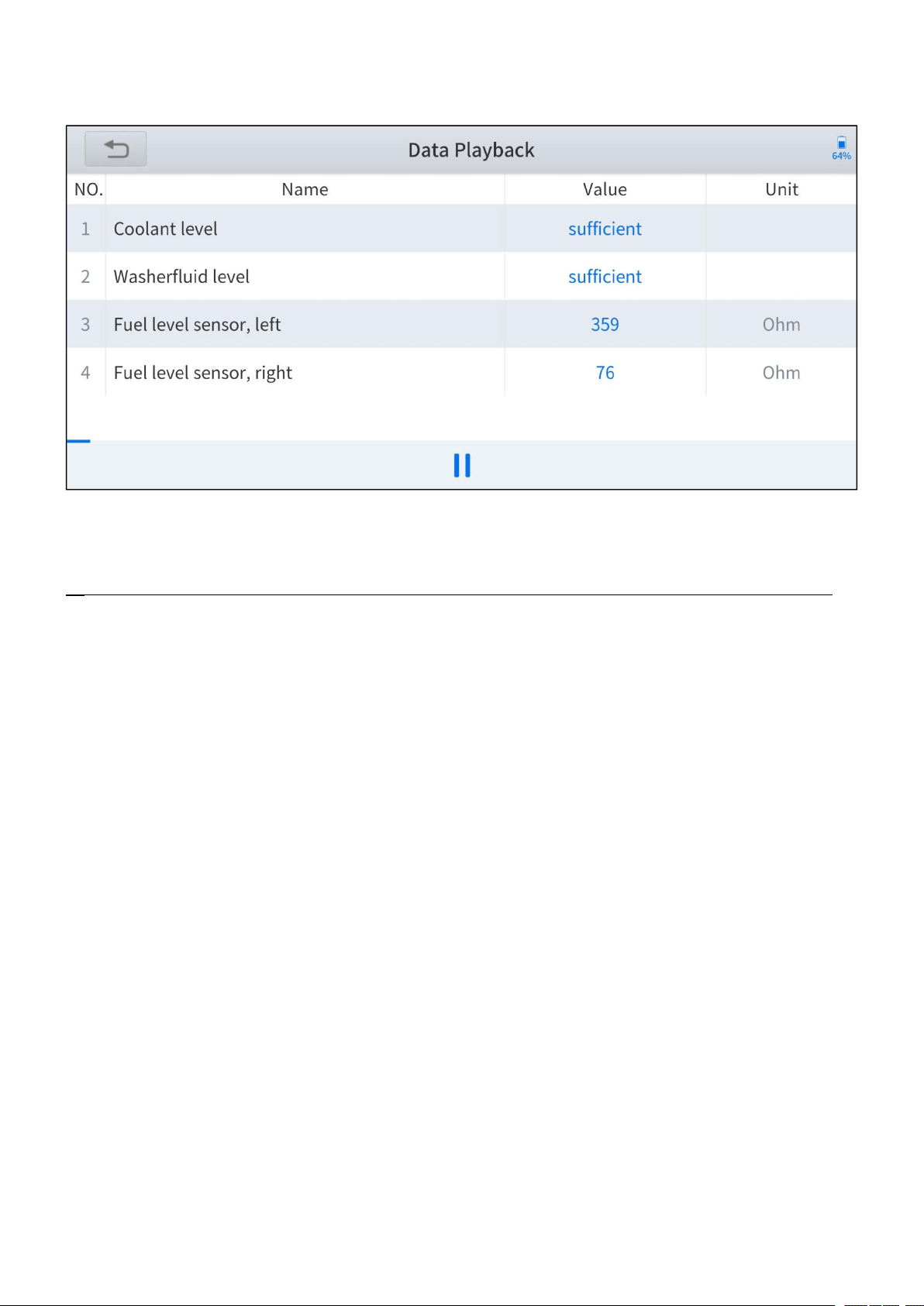
You can play/pause the video and swipe to view all the data recorded.
Figure 6-5 Sample of data playback
The Data Playback videos cannot be extracted, and you can only play them within the App.
—
63
—
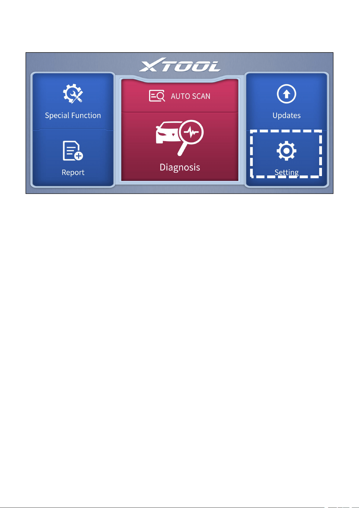
7 SETTING
Figure 7-1 Sample of the main menu screen
Click the Setting button to adjust the default settings and view the information of
the Anyscan Wireless Scan Tool. There are several options available in the system
setting:
Language
Units
Bluetooth
Workshop Information
VCI Information
About
—
64
—
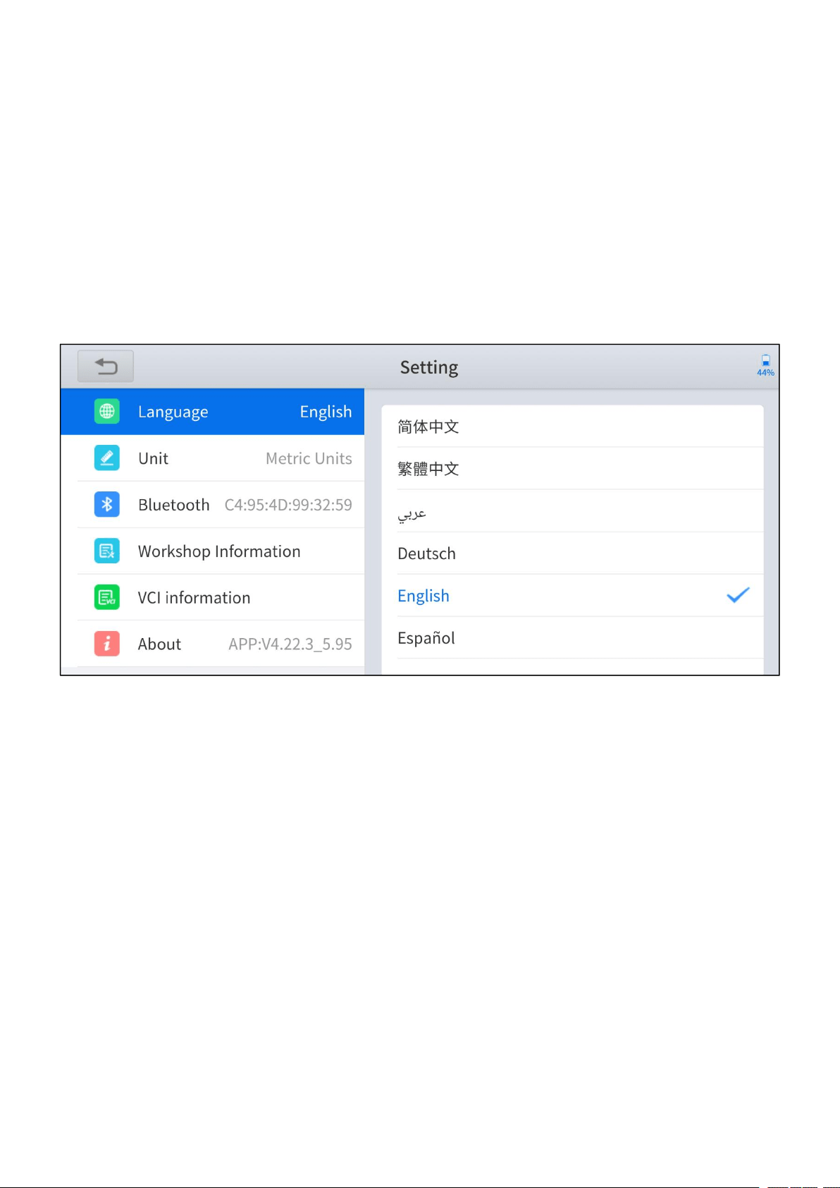
7.1 LANGUAGE
The languages supported by the device are listed in Setting. The default language
is set as English, if you need to switch to other languages, please contact the
dealer to unbind the current language configuration and rebind it to the language
configuration you need to switch. After the configuration is successfully changed,
you can switch the target language.
Figure 7-2 Language of setting
How to change the language of your software?
Step1: Contact your dealer and leave a message about the language you need
and the S/N of your device, The technician will modify the language configuration
for you in the backend system.
Step2: Settings->Language->Choose language
Step3: Back to Updates to update all the software again

—
65
—
7.2 UNITS
You can switch the units shown in the system on your preference. Anyscan
provides you with Metric, Imperial, and U.S. units. You can directly click on the
preferred units, after it switches successfully, a blue tick symbol will be shown
behind that unit’s name.
Figure 7-3 Units of setting
—
66
—
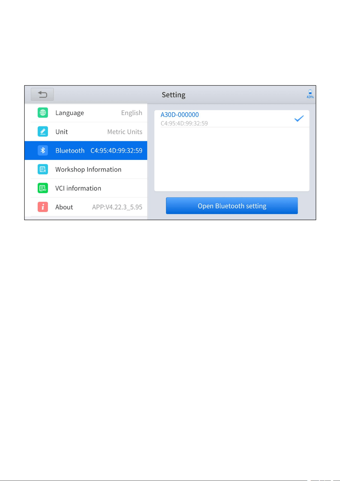
7.3 BLUETOOTH
You can check the Bluetooth connection status here. If you encounter any
communication issues, please first check the Bluetooth status.
Figure 7-4 Bluetooth of setting
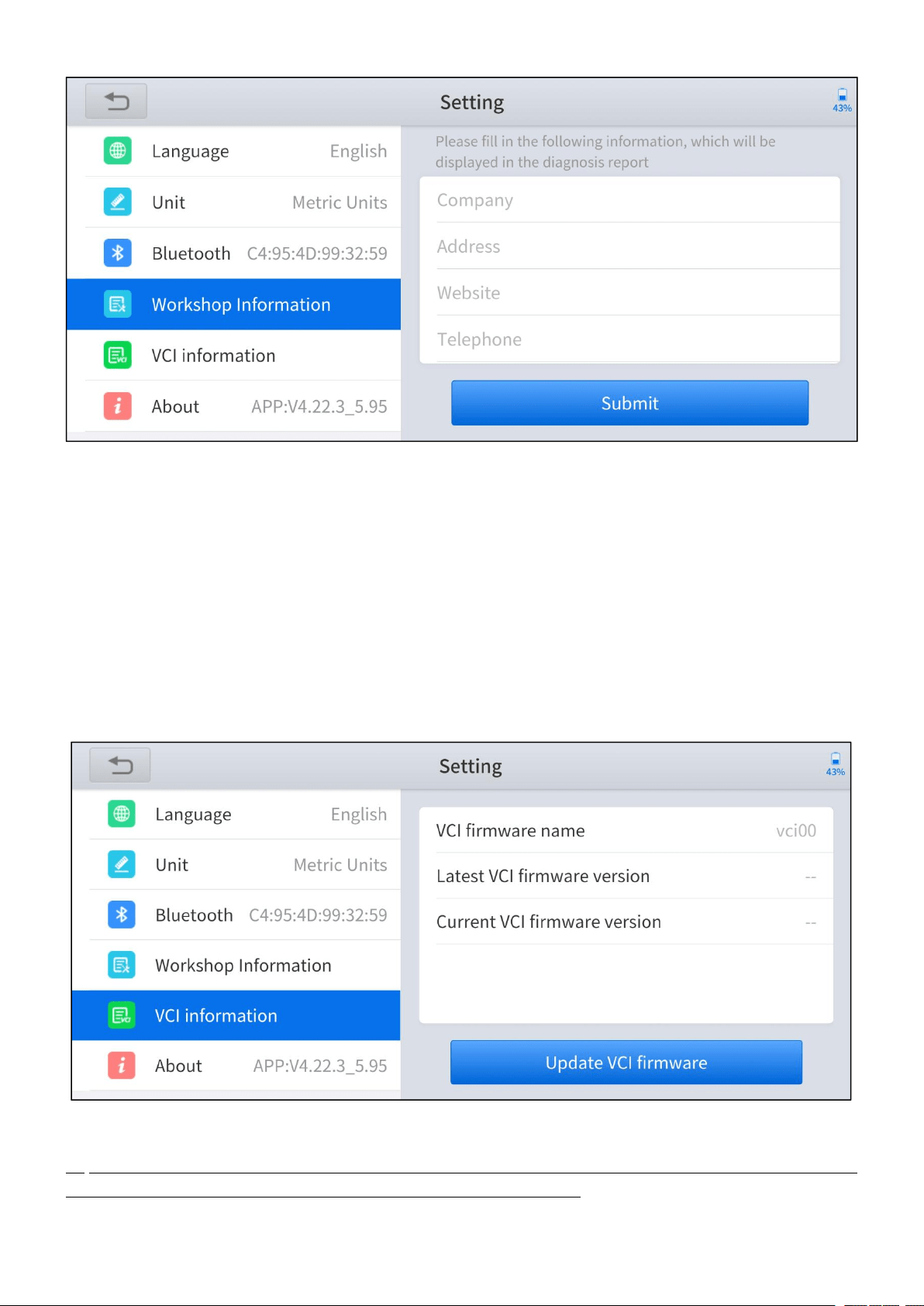
7.4 WORKSHOP INFORMATION
Click on Workshop Information, you can input your workshop information here.
As shown in the figure below, you can fill in the valid information in the
corresponding input boxes and click the Submit button. And then it will show your
workshop information in the diagnosis report, including your company name,
address, website, telephone, mailbox, and contact person.
—
67
—
Figure 7-5 Workshop information of setting
7.5 VCI INFORMATION
You can view the VCI information here, including the VCI firmware name, the latest
firmware version, the currently used firmware version, and the VCI firmware type. If
the current firmware version is not the latest firmware version, you can choose to
update your firmware version by clicking the Update VCI Firmware button.
Figure 7-6 VCI information of setting
You can only update the VCI firmware when you have finished the activation process,
connected to the Bluetooth, and also the vehicle/power supply.
—
68
—
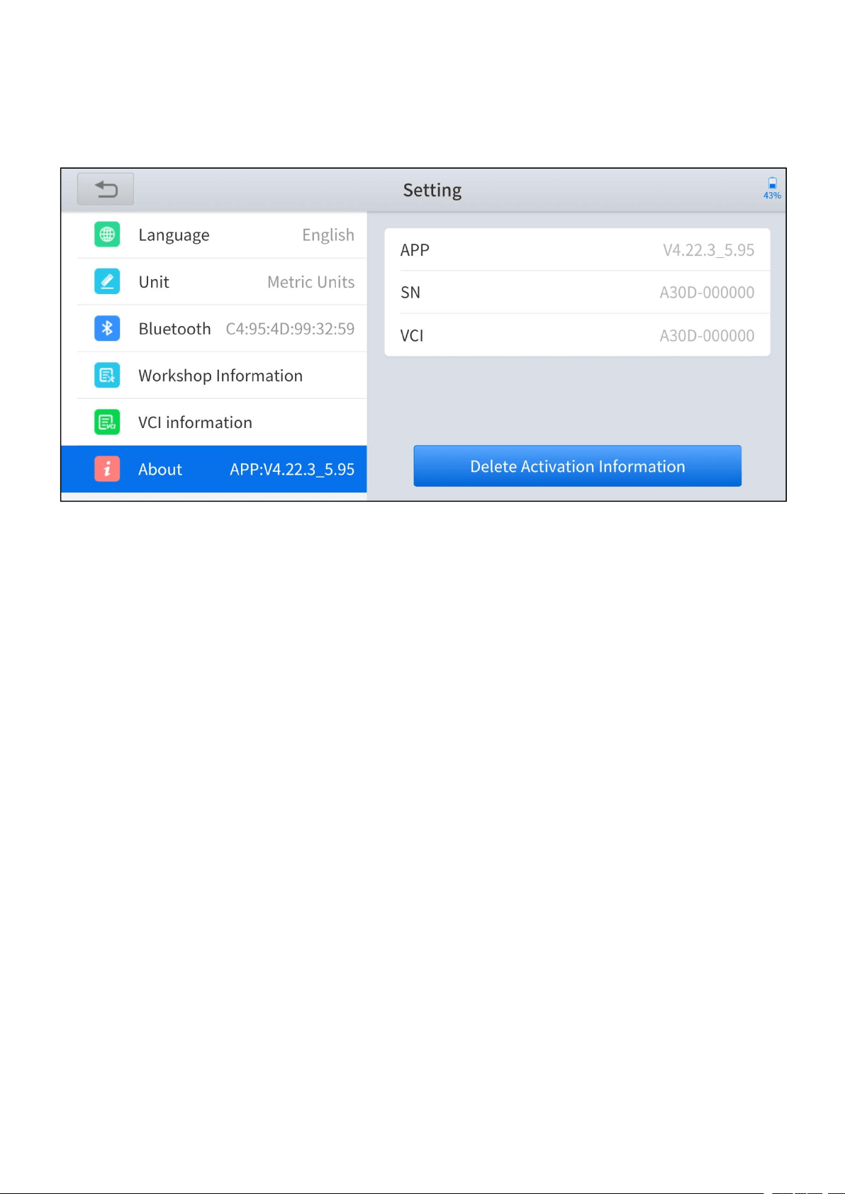
7.6 ABOUT
You can check the serial number and APP version here.
Figure 7-7 About of setting

—
69
—
8 FAQ
Q1: FAILED TO CONNECT BLUETOOTH
1. Please check whether the status of the indicator light of the Anyscan is working
properly.
2. The Bluetooth indicator lights blue when the Bluetooth has successfully
connected; the power indicator lights red when the Anyscan is connected to
the vehicle or power supply properly; the vehicle indicator lights flash green
when the Anyscan is successfully communicated with the vehicle. If the
indicators do not light up, it means that there are hardware defects.
3. Anyscan can log in on multiple mobile devices at the same time, but only one
device can be connected via Bluetooth at one time. If your device lights up in
blue, but you fail to connect your device, please check whether your Anyscan
is automatically paired with other mobile devices.
4. For Android users, the Bluetooth setting of OS will only pair the Anyscan device,
but not actually connecting the Bluetooth, the Bluetooth indicator may not light
up. You may need to connect the Bluetooth within the app, make sure that the
Anyscan device is selected in the Bluetooth setting. Blue tick symbol should
shown next to the selected device.
Q2: FAILED TO GENERATE DIAGNOSIS REPORT
1. Currently, only the diagnosis function supports the generation of diagnosis
reports. No diagnosis reports will be generated after performing the special
functions.

—
70
—
2. After entering the diagnosis menu, you need to perform specific functions
before the system can generate a diagnosis report normally.
3. After executing the specific diagnosis function, you need to click the return
button step by step to return to the main menu in order to generate the
diagnosis report successfully.
Q3: FAILED TO EXTRACT FILES
For Diagnosis Report
Click the Print PDF Report button in the diagnosis report, select the PDF reader to
open the file, and the reader can send and save the PDF report. The diagnosis
report is saved in the ‘Diagnosis’ folder on your mobile devices.
For Data Playback video
The Data Playback videos are encrypted files and the extraction function is
temporarily not supported.
Q4: HOW TO UPGRADE FIRMWARE
Click the Update VCI firmware button found in the VCI Information menu of
Setting to manually update the firmware version of the device. Please be
reminded you can only update the VCI firmware when you have finished the
activation process, connected to the Bluetooth, and also the vehicle/power supply.
Q5: HOW TO GENERATE AND UPLOAD DIAGNOSTIC LOG FILES
The Anyscan will automatically generate and store the diagnostic logs. When the

—
71
—
device is connected to the Internet, it will automatically upload all the stored
diagnostic logs to the backend system.
Q6: HOW TO SWITCH LANGUAGE
1. Contact your dealer and leave a message about the language you need and
the S/N of your device, The technician will modify the language configuration
for you in the backend system.
2. Settings->Language->Choose language
3. Back to Updates to update all the software again
Q7: FAILED TO DIAGNOSE VEHICLE
1. Contact your dealer to confirm whether the vehicle model is supported by the
scan tool you owned.
2. Check whether the vehicle is properly connected. (The requirements may vary
from brand or model, please follow the instructions displayed)
3. Confirm whether you have entered the correct diagnosis menu
4. Try whether the AUTO SCAN function can assist you to enter the correct
diagnosis menu
5. Check whether the software is the latest version, if not, please update to the
latest version first.

—
72
—
Q8: FAILED TO ACTIVATE OR REGISTER
For ‘Activation Failed’
Generally caused by network instability, please switch to a more stable network
and try to activate again.
For ‘Registration Failed’
Generally, it is caused by the connection timeout or the sending timeout, please
check whether you have blocked the outgoing network traffic to non-US regions
like China. We recommend that you unblock and try to register again.

—
73
—
9 WARRANTY & SERVICES
LIMITED ONE YEAR WARRANTY
Shenzhen Xtooltech Intelligent Co., LTD.(the Company) warrants to the original
retail purchaser of this XTOOL device that should this product or any part thereof
during normal usage and under normal conditions be proven defective in material
or workmanship that results in product failure within one year from the date of
purchase, such defect(s) will be repaired, or replaced (with new or rebuilt parts)
with Proof of Purchase, at the Company’s option, without charge for parts or labor
directly related to the defect(s).
The Company shall not be liable for any incidental or consequential damages
arising from the use, misuse, or mounting of the device.
This warranty does not apply to:
1. Products subjected to abnormal use or conditions, accident, mishandling,
neglect, unauthorized alteration, misuse, improper installation/repair or,
improper storage;
2. Products whose mechanical serial number or electronic serial number has
been removed, altered, or defaced;
3. Damage from exposure to excessive temperature or extreme environmental
conditions;
4. Damage resulting from connection to, or use of any accessory or other product
not approved or authorized by the Company;
5. Defects in appearance, cosmetic, decorative, or structural items such as

—
74
—
framing and non-operating parts;
6. Products damaged from external causes such as fire, dirt, sand, battery
leakage, blown fuse, theft, or improper usage of any electrical source.

—
75
—
APPENDIX
The Anyscan App (from version v4.23.6) will not access the photos, contacts,
messages on the mobile devices. Therefore, no related privacy issues will be
involved. The access warning pop-up message is generated automatically by the
mobile devices when Anyscan requests permission to access the storage. The
access warning text and content may vary across the brands of the mobile devices.
For example, Samsung devices will prompt as“Allow Anyscan to access photos,
media, and files on your device?”.
Legal Statement and Privacy Right Policy
Reminders
Your trust is of great importance to us. We deeply understand the importance of
user information security and will take security measures in accordance with laws
and regulations to protect your user information to keep it secure and under control.
Therefore, Shenzhen Xtooltech Intelligent Technology Co., Ltd.
(“we”) formulates this Legal Statement and Privacy Right Policy (this “Statement
and Policy”) and reminds you that: Before using our services, please carefully read
and thoroughly understand this Legal Statement and Privacy Right Policy and
confirm that you have fully understood and agreed to this Statement and Policy
before using relevant products or services. By using our services, you
acknowledge that you accept and recognize the contents hereof.

—
76
—
If you have any questions, comments, or suggestions on the contents of this
Statement and Policy, you may contact us via the online channel.
Definition
Personal Information: means all kinds of information, recorded electronically or
otherwise, that is sufficient to identify a natural person on its own or in combination
with other information, including but not limited to name, birth date, identification
certificate number, personal biometric information, address, and telephone number
of a natural person. The Personal Information referred to herein is your personal
information that we collect, transmit, store, use and share for the purpose of
providing services to you.
Business Data: means the data you upload, download, store, or process using
your services that is different from Personal Information.
Legal Statement
1. Ownership of Rights
1.1. Our logo, ‘XTOOL’, ‘Anyscan’ and other texts, graphs and combination thereof,
other marks and symbols of ours and our service names are the registered
trademarks of ours and our Affiliates’ in China and other countries. Without our

—
77
—
written authorization, no one may display, use or otherwise process (including
without limitation reproduce, disseminate, show, mirror, upload and download) any
of the said trademarks in any way or represent to others that you have the right to
display, use or otherwise process any of the said trademarks.
1.2. The intellectual property rights in all of our products, services, technologies
and all applications (“Technical Services”) shall vest in us or their right owners.
1.3. Unless otherwise stated by us, all rights (including but not limited to the
copyright, trademark right, patent right, trade secret and any other related rights) in,
of and to all documents and other information (including but not limited to texts,
graphs, pictures, photos, audios, videos, icons, colors, layout and electronic
documents) published by us on our website are vested in us. Without our
permission, no one may use the said information (including but not limited to
monitoring, reproducing, rebroadcasting, displaying, mirroring, upload, and
downloading any contents in our website via programs or devices). Where any
person is authorized to browse, reproduce, print or disseminate any information on
our website, such information shall not be used for commercial purposes and this
statement of rights must be included when using all or any portion of the
information.
2. Limitation on Liability
2.1. We hereby remind you that you shall abide by laws of the People’s Republic of

—
78
—
China in using our services, and you shall not endanger cyber security or utilize our
services to engage in activities that infringe upon others’ reputation right, privacy,
intellectual property rights or other legitimate interests. Notwithstanding the
aforesaid reminder, we will assume no liability for your purposes of using our
services.
3. Protection of Intellectual Property Rights
We respect intellectual property rights and oppose and combat any infringement
upon intellectual property rights. If any organization or individual believes that the
contents of our client pages may infringe upon its/his/her legitimate interests, such
organization or individual may issue a written notice of claims to us and we will deal
with the same bylaw as soon as possible after receipt of applicable notice from the
intellectual property right owner.
Privacy Right Policy
We respect and protect user information and will treat the same with the great duty
of care. When you use our services, we will collect, process and disclose your
personal information in accordance with this Privacy Right Policy. With this Privacy
Right Policy, we intend to clearly introduce to you how we deal with your Personal
Information.
Therefore, we advise you to read this Privacy Right Policy completely to

—
79
—
understand the means of protecting your privacy right.
If you have any questions, comments or suggestions, please contact us via the
contact information we provide.
This Policy will help you understand the following:
1. Scope of Application
2. Collection and Use of User Information
3. Sharing, Transfer and Disclosure of User Information
4. User Information Management
5. Use of Cookie and Similar Technologies
6. Personal Information Security
7. Protection of Minors
8. Update of This Privacy Right Policy
9. How to Contact Us

—
80
—
1. Scope of Application
1.1. This Privacy Right Policy shall apply only to your use of our services, including
the provision of network distribution, control and management of smart devices to
you.
1.2. This Privacy Right Policy shall not apply to services provided by third parties to
you. For example, this Privacy Right Policy shall not apply to the information you
provide to a third party who relies upon our platform to provide services to you.
1.3 The Legal Statement and Privacy Right Policy is the general privacy right policy
for Shenzhen Xtooltech Intelligent Technology Co., Ltd, and all the user rights and
information security measures therein apply to our users. In case there is any
discrepancy or conflict between the Legal Statement and Privacy Right Policy and
this Privacy Right Policy, this Privacy Right Policy shall prevail.
2. Collection and Use of User Information
2.1. Member information
2.1.1. If you have registered any XTOOL account, you may log in to our services
using that account. If so, the real-name information (name, phone number/email)
you provide for the registration of XTOOL account will be synchronized with us.

—
81
—
2.2. Provision of Technical Services to you
Information provided by you to us includes:
2.2.1. The information you are requested to provide is subject to that listed on our
web page. If you do not intend to use certain services, you are not required to
provide relevant information.
Information collected by us during your use of the services
2.2.2. Device information: we will receive and record the information relating to the
smart device you use in accordance with the authority you grant in the installation
and use of the application (such as the information of the smart device the network
distribution is completed by us, including device model, operating system version,
device setting, unique device identifier and other Software and hardware
characteristic information).
2.2.3. Log information: When you use the services provided by our website or
client, we will automatically collect detailed information relating to your use of our
services and save them as network logs, such as your searches, IP addresses,
types of browsers, telecommunication service providers, languages, visit dates and
times, and web pages visited by you.

—
82
—
Information provided by the service provider of the smart device when you use our
services:
2.2.4. Smart device operating information (such as the information of operating
mode, current temperature, current fan speed and current relative humidity of a
smart air-conditioner).
2.2.5. Location information: When you turn on the positioning function and use
services that are based on it, we will collect your location info, so that you do not
need to manually enter your own geographic coordinates to obtain related services.
We use various technologies for positioning, including IP addresses, GPS, and
other sensors that can provide location info (including info of WLAN access points
and base stations). You can turn off the positioning permission through system
settings. You may not be able to use the related services or functions, or you may
not be able to achieve the intended effects of the related services.
2.2.6. Please note that the device information or operating information alone is not
sufficient to identify a certain natural person. If we combine such non-Personal
Information with other information to identify a certain natural person or use the
same in combination with Personal Information, then such non-Personal
Information will be deemed as Personal Information during such combination, and
we will anonymize and de-identify such Personal Information unless with your
authorization or it is otherwise provided by laws and regulations.
2.3. We use the user information provided by you or collected by us for the

—
83
—
following purposes:
2.3.1. To provide you with services and maintain and improve such services;
2.3.2. To promote and introduce products to you to the extent permitted by laws
and regulations;
2.3.3. We may use your Personal Information to prevent, identify and investigate
fraud, any act endangering security, illegal activity, or any other act which breaches
or violates any agreement, policy or rule with or of us or any of our Affiliates so as
to protect the legitimate rights and interests of you, any of our other users, us or
any of our Affiliates;
2.3.4. We may combine your information obtained from a certain service with
information from any other service so as to provide you with services, personalized
content and advice;
2.3.5. For any other purpose as permitted by you.
3. Sharing, Transfer and Disclosure of User Information
3.1 Sharing
We will not share your user information with any other organization or individual,

—
84
—
except in the following circumstances:
3.1.1. Sharing with express consent: We will share your user information with other
parties with your express consent;
3.1.2. Sharing as required by laws: We may share your user information as
required by laws, regulations, litigation or arbitration, or by an administrative or
judicial authority in accordance with laws;
3.1.3. Sharing with authorized partners: As we may engage our trusted partners to
provide services, we might share certain Personal Information with such partners
in order to provide better customer service and optimize the user experience. We
will only share your user information for the lawful, proper, necessary, specific and
express purpose to the extent required for providing the services. Our partners
have no right to use the shared user information for any other purpose.
Currently, the type of our authorized partners includes suppliers, service providers
and others. We send the information to the suppliers, service providers and other
partners who support our business by providing underlying Technical Services,
consultation, analysis and other professional services.
We will conclude a strict confidentiality agreement and information protection
agreement with the companies, organizations and individuals with whom we share
user information to require them to treat user information in accordance with our

—
85
—
instruction, this Privacy Right Policy and any other relevant confidentiality and
security measures.
3.2. Transfer
We will not transfer your user information to any company, organization or
individual, except in the following circumstances:
3.2.1. Transfer with express consent: We will transfer your user information to other
parties upon obtaining your express consent;
3.2.2. In case of any acquisition, merger or insolvency liquidation, or other
circumstances involving merger, acquisition or insolvency liquidation, of us with
any other legal entity, if the transfer of user information is involved, we will require
the new company, organization or individual in possession of your user information
to continue to be bound by this Policy, or we will require such company,
organization and individual to obtain your authorization and consent again.
3.3 Disclosure
We will disclose your user information only under the following circumstances:
3.3.1.We may disclose your user information with your express consent or at your
voluntary option;

—
86
—
3.3.2. In order to protect the personal and property safety of our platform, our
Affiliates or the public, we may disclose your user information in accordance with
applicable laws or your relevant agreements or rules.
3.4. Exceptions to obtaining prior authorization and consent for sharing, transfer
and disclosure of user information Your user information may be shared,
transferred or disclosed without your prior authorization and consent under any of
the following circumstances:
3.4.1. National security and national defense security are involved;
3.4.2. Public security, public health or major public interests are involved;
3.4.3. Criminal investigation, prosecution, judgment and enforcement are involved;
3.4.4. For the purpose of protecting your or other individual’s life, property and
other major lawful rights and interests, where it is hard to obtain your prior consent;
3.4.5. The Personal Information is disclosed voluntarily by you to the public;
3.4.6. The Personal Information is collected from the information disclosed through
lawful public channels, such as lawful news reports or information disclosure by the
government.

—
87
—
4. User Information Management
4.1. You may log in to the “administrator page” of our client to inquire and
administrate (change or delete) the basic business information (house area, family
status, and house address) and family member information submitted by you for
the use of our services.
4.2. You may submit a request for deletion of user information to us under any of
the following circumstances:
4.2.1. Our user information processing violates any law or regulation;
4.2.2. We collect or use your user information without your express consent;
4.2.3. Our Personal Information processing materially breaches the agreement
with you.
For the purpose of security, you may be required to provide a written request or to
otherwise identify yourself. We may ask you to identify yourself before processing
your request.
5. Use of Cookie and Similar Technologies

—
88
—
5.1. In order to ensure the normal operation, provide you with a more convenient
visit experience and recommend contents that may be of interest to you, we will
store small data files named “cookie” on your client. Cookies usually contain
identifiers, site names and certain numbers and characters. We can only read the
cookies provided by us.
5.2. Cookies are able to store your preference. When you visit our website next
time, we will be able to display the information you need.
5.3. You may manage cookies according to your preference or clear all cookies
stored on your mobile device. However, if you do so, you need to change the user
setting each time you visit our website.
5.4. In addition to cookies, we will use beacon, pixel tag and other similar
technologies on our website.
6. User Information Security
6.1. We attach great importance to the security of your information. We endeavor
to take all kinds of physical, electronic and administrative security measures to
protect your use information from unauthorized access, disclosure, use,
manipulation, damage or loss. We will use encryption techniques to improve the
security of user information, use trusted protection mechanisms to protect
user-information from malicious attacks, deploy access control mechanism to

—
89
—
ensure the user-information is accessible only to authorized personnel to the
maximum extent possible, and hold training sessions about security and privacy
protection to enhance our employee’s awareness of the importance of user
information protection.
6.2. We will take reasonable and practical measures to avoid collecting irrelevant
and unnecessary user information to the maximum extent possible. We will retain
your user information only for the period as is necessary to achieve the purposes
outlined in this Policy unless it is agreed by you and us to prolong the retention
period or permitted by law. Upon the expiration of such retention period, we will
delete or anonymize your Personal Information.
6.3. Upon the occurrence of any user information security incident (such as
disclosure or loss), we will, in accordance with the requirements of laws and
regulations, notify you of the following matters: basic information and possible
influence of such security incident, handling measures we have taken or will take,
suggestions on how you may prevent or reduce risks on your own, and remedies to
be taken for you. We will notify you of the relevant information of such incidents
through email, letter, phone, and push notification. If it is difficult to notify each user
information subject one by one, we will publish the announcement reasonably and
effectively.
6.4. In addition, we will also report the handling of user information security
incidents according to the requirements of regulatory authorities.

—
90
—
6.5. If the operation of our products or services stops, we will take reasonable
measures to protect your user information security, including timely stop further
collection of your user information, sending you a notice thereof on a personal
basis or in the form of an announcement, and deleting or anonymizing your
Personal Information held by us.
6.6. If we intend to use your user information for any purpose other than those
specified when we collect the same or beyond the scope that is directly or
reasonably relevant, we will inform of you the same again and obtain your express
consent.
7. Protection of Minors
We attach importance to the protection of the Personal Information of minors. If
you are a minor, we suggest that you ask your guardian to read this Privacy Right
Policy carefully, and you may use our services and/or provide us with information
subject to the consent of your guardian.
8. Update of This Privacy Right Policy
8.1. There might be modifications of this Privacy Right Policy.
8.2. Without your express consent, we will not restrict the rights you are entitled to

—
91
—
under this Policy. We will publish any modification of this Policy on a specific web
page.
8.3. With respect to material modifications, we will also provide a more noticeable
notice (with respect to certain services, we will give notice in the form of an
announcement to specify the modifications of this Policy in detail).
8.4. Material change herein includes but is not limited to:
8.4.1. Material change of our service mode, such as the purpose of processing
user information, the type of user information we process and the way in which we
use user information;
8.4.2. Material change of control and organizational structure, such as the change
of owner due to business adjustment or bankruptcy buyout;
8.4.3. Change of the main subject to whom the sharing, transfer or disclosure of
user information is made;
8.4.4. Material change of your rights relating to the participation of user information
processing or the exercise manner thereof;
8.4.5. Change of our department responsible for the security of user information
processing, its contact information or complaint channel;

—
92
—
8.4.6. High risk is indicated in the user information security impact assessment
report.
9. How to Contact Us
If you have any questions or comments on the contents of this Statement and
Policy or the practice of this Privacy Right Policy, you may contact us via the online
channel.

—
93
—
Shenzhen Xtooltech Intelligent Co., Ltd
Company address: 17&18/F, Building A2, Creativity City, Liuxian Avenue, Nanshan
District, Shenzhen, China
Factory address: 2/F, Building 12, Tangtou Third Industrial Zone, Shiyan Street, Baoan
District, Shenzhen, China
Service-Hotline: 0086-755-21670995/86267858
Email: marketing@xtooltech.com
supporting@xtooltech.com
Fax: 0755-83461644
Website: www.Xtooltech.com