PTZ Camera
RGB10X-USB-BK
User Manual

© Xiamen RGBlink Science & Technology Co., Ltd.
1
Content
Declarations.................................................................................................................................................................. 3
FCC/Warranty........................................................................................................................................................... 3
Operators Safety Summary........................................................................................................................................4
Installation Safety Summary.................................................................................................................................. 4
Chapter 1 Your Product...............................................................................................................................................6
1.1 In the Box............................................................................................................................................................6
1.2 Product Overview.............................................................................................................................................. 6
1.2.1 Product Model............................................................................................................................................ 6
1.2.2 Dimension................................................................................................................................................... 6
1.2.3 Main Features.............................................................................................................................................7
Chapter 2 Install Your Product................................................................................................................................9
2.1 Camera Interface Explanation.........................................................................................................................9
2.1.1 External Interface.......................................................................................................................................9
2.1.2 RS-232 Interface......................................................................................................................................10
2.2 Bracket Mount..................................................................................................................................................11
Chapter 3 Use Your Product....................................................................................................................................14
3.1 Video Output.................................................................................................................................................... 14
3.1.1 Power on initial configuration.................................................................................................................14
3.1.2 Video Output.............................................................................................................................................14
3.2 Remote Controller........................................................................................................................................... 14
3.2.1 Keys Instruction........................................................................................................................................14
3.3 Menu Setting....................................................................................................................................................16
3.3.1 Main Menu................................................................................................................................................ 16
3.3.2 System Setting......................................................................................................................................... 17
3.3.3 Camera Setting........................................................................................................................................ 18
3.3.4 P/T/Z.......................................................................................................................................................... 21
3.3.5 Version.......................................................................................................................................................21
3.3.6 Restore Default........................................................................................................................................ 22
Chapter 4 Ordering Codes....................................................................................................................................... 23
4.1 Product..............................................................................................................................................................23
Chapter 5 Support..................................................................................................................................................... 24
5.1 Contact us........................................................................................................................................................ 24
5.2 Camera Maintenance and Troubleshooting............................................................................................... 27
5.2.1 Camera Maintenance..............................................................................................................................27
5.2 Troubleshooting...........................................................................................................................................27
Chapter 6 Appendix...................................................................................................................................................28

© Xiamen RGBlink Science & Technology Co., Ltd.
2
6.1 VISCA Protocol List........................................................................................................................................ 28
6.1.1 Camera Return Command.....................................................................................................................28
6.1.2 Camera Control Command.................................................................................................................... 28
6.1.3 Inquiry Command.................................................................................................................................... 31
6.2 Pelco-D Protocol Command List.................................................................................................................. 33
6.3 Pelco-P Protocol Command List...................................................................................................................34
6.4 Revision History...............................................................................................................................................34

© Xiamen RGBlink Science & Technology Co., Ltd.
3
Thank you for choosing our product!
This User Manual is designed to show you how to use this camera quickly and make use of all the
features. Please read all directions and instructions carefully before using this product.
Declarations
FCC/Warranty
Federal Communications Commission (FCC) Statement
This equipment has been tested and found to comply with the limits for a class A digital device, pursuant
to Part 15 of the FCC rules. These limits are designed to provide reasonable protection against harmful
interference when the equipment is operated in a commercial environment. This equipment generates,
uses, and can radiate radio frequency energy and, if not installed and used in accordance with the
instruction manual, may cause harmful interference to radio communications. Operation of this equipment
in a residential area may cause harmful interference, in which case the user will be responsible for
correcting any interference.
Guarantee and Compensation
RGBlink provides a guarantee relating to perfect manufacturing as part of the legally stipulated terms
of guarantee. On receipt, the purchaser must immediately inspect all delivered goods for damage
incurred during transport, as well as for material and manufacturing faults. RGBlink must be informed
immediately in writing of any complains.
The period of guarantee begins on the date of transfer of risks, in the case of special systems and
software on the date of commissioning, at latest 30 days after the transfer of risks. In the event of justified
notice of compliant, RGBlink can repair the fault or provide a replacement at its own discretion within an
appropriate period. If this measure proves to be impossible or unsuccessful, the purchaser can demand a
reduction in the purchase price or cancellation of the contract. All other claims, in particular those relating
to compensation for direct or indirect damage, and also damage attributed to the operation of software as
well as to other service provided by RGBlink, being a component of the system or independent service,
will be deemed invalid provided the damage is not proven to be attributed to the absence of properties
guaranteed in writing or due to the intent or gross negligence or part of RGBlink.
If the purchaser or a third party carries out modifications or repairs on goods delivered by RGBlink, or if
the goods are handled incorrectly, in particular if the systems are commissioned operated incorrectly or if,
after the transfer of risks, the goods are subject to influences not agreed upon in the contract, all
guarantee claims of the purchaser will be rendered invalid. Not included in the guarantee coverage are
system failures which are attributed to programs or special electronic circuitry provided by the purchaser,
e.g. interfaces. Normal wear as well as normal maintenance are not subject to the guarantee provided by
RGBlink either.
The environmental conditions as well as the servicing and maintenance regulations specified in this
manual must be complied with by the customer.

© Xiamen RGBlink Science & Technology Co., Ltd.
4
Operators Safety Summary
The general safety information in this summary is for operating personnel.
Do Not Remove Covers or Panels
There are no user-serviceable parts within the unit. Removal of the top cover will expose dangerous
voltages. To avoid personal injury, do not remove the top cover. Do not operate the unit without the cover
installed.
Power Source
This product is intended to operate from a power source that will not apply more than 230 volts rms
between the supply conductors or between both supply conductor and ground. A protective ground
connection by way of grounding conductor in the power cord is essential for safe operation.
Grounding the Product
This product is grounded through the grounding conductor of the power cord. To avoid electrical shock,
plug the power cord into a properly wired receptacle before connecting to the product input or output
terminals. A protective-ground connection by way of the grounding conductor in the power cord is
essential for safe operation.
Use the Proper Power Cord
Use only the power cord and connector specified for your product. Use only a power cord that is in good
condition. Refer cord and connector changes to qualified service personnel.
Use the Proper Fuse
To avoid fire hazard, use only the fuse having identical type, voltage rating, and current rating
characteristics. Refer fuse replacement to qualified service personnel.
Do Not Operate in Explosive Atmospheres
To avoid explosion, do not operate this product in an explosive atmosphere.
Installation Safety Summary
Safety Precautions
For all camera installation procedures, please observe the following important safety and handling rules to
avoid damage to yourself and the equipment.
To protect users from electric shock, ensure that the chassis connects to earth via the ground wire
provided in the AC power Cord.
The AC Socket-outlet should be installed near the equipment and be easily accessible.

© Xiamen RGBlink Science & Technology Co., Ltd.
5
Unpacking and Inspection
Before opening camera shipping box, inspect it for damage. If you find any damage, notify the shipping
carrier immediately for all claims adjustments. As you open the box, compare its contents against the
packing slip. If you find any shortages, contact your sales representative.
Once you have removed all the components from their packaging and checked that all the listed
components are present, visually inspect the system to ensure there was no damage during shipping. If
there is damage, notify the shipping carrier immediately for all claims adjustments.
Site Preparation
The environment in which you install your camera should be clean, properly lit, free from static, and have
adequate power, ventilation, and space for all components.
Electric Safety
Installation and operation must accord with electric safety standard
Polarity of power supply
The power supply of the product is ±12V, the max electrical current is 2A .Polarity of the power
supply drawing.
Careful of installation
Never move the camera by seizing the camera head. Don’t rotate camera head by hand; otherwise,
mechanical trouble will occur.
This series item must be put on the smooth desk or platform, and it can not be installed slant ways;
If the camera is installed on TV or computer, the base can be fixed by four double‐sided adhesive trays.
Don’t apply in corrosive liquid, as or solid environment to avoid the cover which is made up of organic
material.
To make sure no obstacle in rotation range.
Never power on before installation is completed.
Don’t disassemble discretionarily.
We are not responsible for any unauthorized modification or dismantling.
© Xiamen RGBlink Science & Technology Co., Ltd.
6
Chapter 1 Your Product
1.1 In the Box
Standard:Power Adapter × 1,USB2.0 cable × 1,Remote control × 1
Optional:ceiling mount,wall mount
USB2.0 video cable: If USB2.0 video cable is required for power supply without power adapter, in which power is
supplied by red end and USB video signal is transmitted by black end; if power adapter is used, USB2.0 video cable
is not required for power supply, and ordinary USB2.0 video cable is enough.
1.2 Product Overview
1.2.1 Product Model
The User Manual is applicable to: 10X PTZ Camera: RGB10X-USB-BK
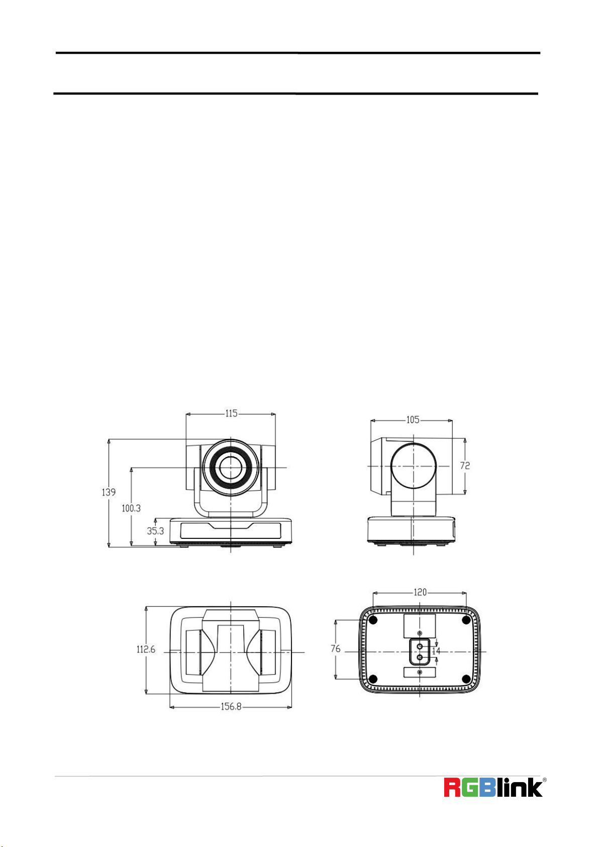
1.2.2 Dimension
Product Dimension

© Xiamen RGBlink Science & Technology Co., Ltd.
7
1.2.3 Main Features
Camera Performance
This series camera has perfect functions, superior performance and rich video output interfaces; Featuring with
advanced ISP processing algorithms, offering vivid and high resolution video with a strong sense of depth and
fantastic color rendition.
Full HD Resolution: 1/2.9 inch high quality CMOS sensor. Resolution is up to 1920x1080 with frame rate up
to 30 fps.
Multiple Optical Zoom Lens: 10X optical zoom lens.
Leading Auto Focus Technology: Fast, accurate and stable auto focusing technology.
Low Noise and High SNR: Super high SNR image is achieved with low noise CMOS. Advanced 2D/3D noise
reduction technology further reduces the noise while ensuring high image clarity.
Control Interface: RS485, RS232 (cascade connection)
Multiple Control Protocol: Support VISCA, PELCO-D, PELCO-P protocols; Support automatic identification
protocols.
Quiet Pan / Tilt Movement: With high accuracy step driving motor, camera can pan / tilt extremely quiet and
smooth.
Multiple presets: Up to 255 presets (10 presets via remote control).
Multiple Application: Online-education, Lecture Capture, Webcasting, Video conferencing, Tele-medicine,
Unified Communication, Emergency command and control systems, etc.
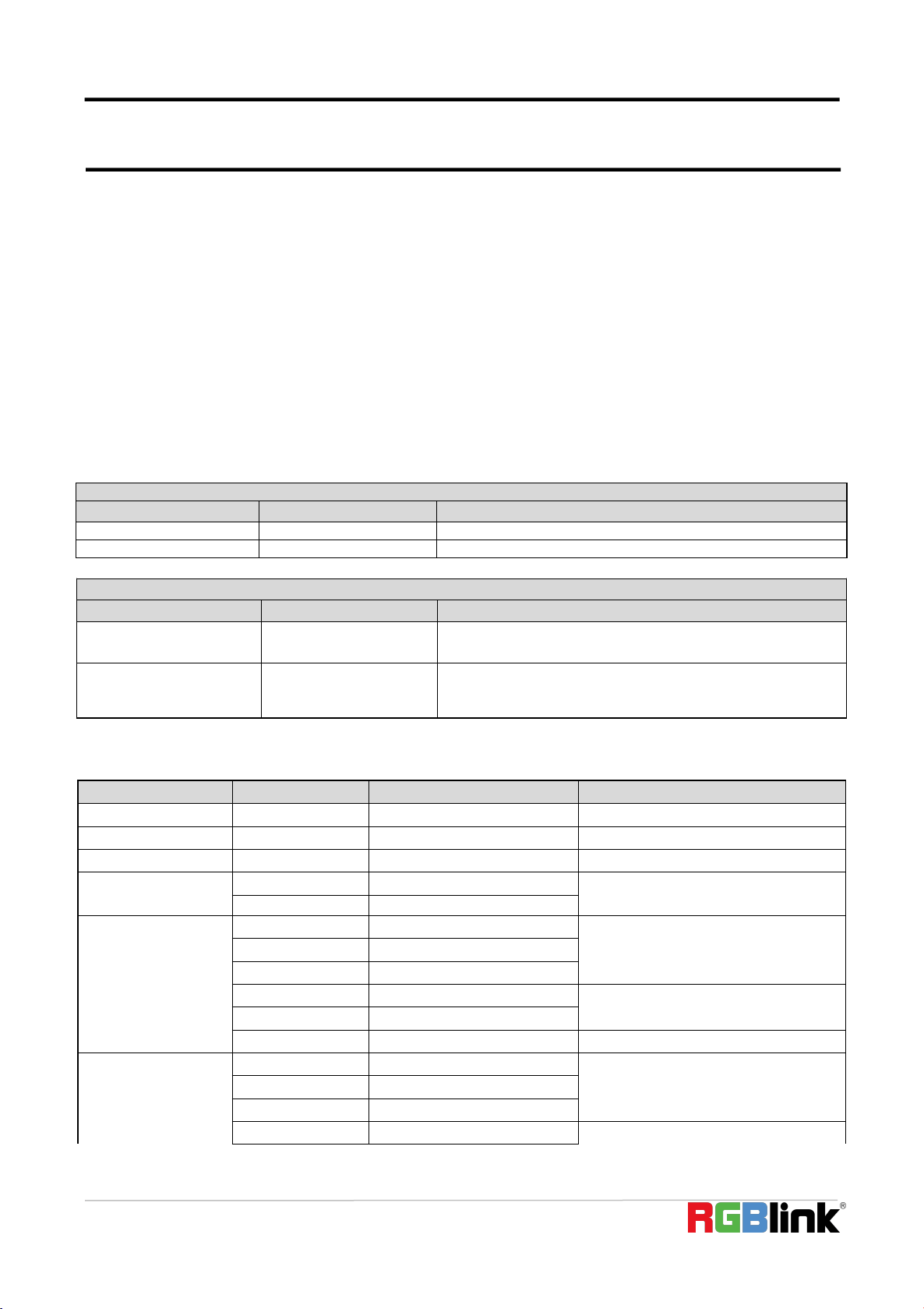
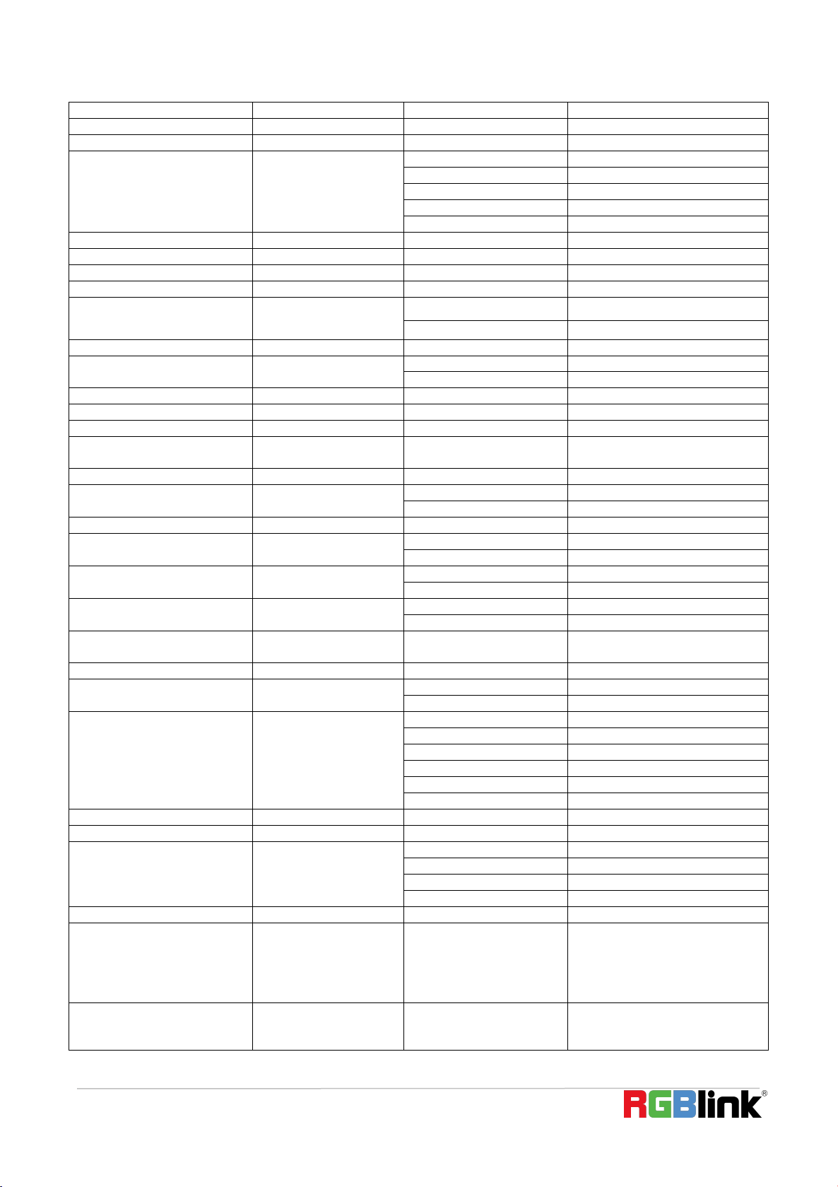
Technical Parameter
Model
10X
Camera Parameter
Sensor
1/2.9 inch high quality CMOS sensor
Effective Pixels
2.07 megapixel, 16
:
9
Video Format
1920
×
1080P@30 fps/25fps
;
1280
×
720P@30fps/25fps
;
1024
×
576P@30fps/25fps
;
960
×
540P@30fps/25fps
;
800
×
448P@30fps/25fps
;
640
×
360P@30fps/25fps
;
320
×
176P@30fps/25fps,etc
View Angle
8.8
° ~
66
°
Focus Length
f=4.34mm
~
41.66mm
AV
F1.85 ~ F2.43
Optical Zoom
10X
Digital Zoom
10X
Minimum
Illumination
0.5Lux(F1.8, AGC ON)
DNR
2D
﹠
3D DNR
White Balance
Auto / Manual/ One
Push//3000K/3500K/4000K/4500K/5000K/5500K/6000K/6500K/7000K
Focus
Auto / Manual/ One Push Focus
Exposure
Auto / Manual
© Xiamen RGBlink Science & Technology Co., Ltd.
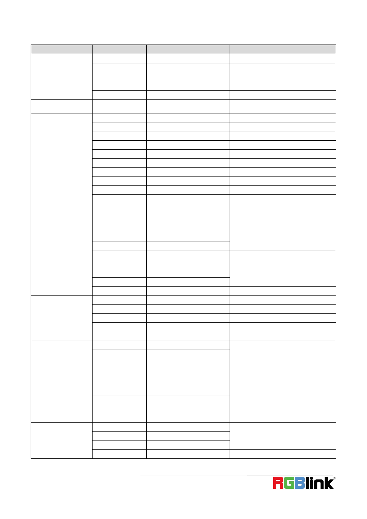
8
BLC
On/Off
Video Adjustment
Brightness, Color, Saturation, Contrast, Sharpness, B/W mode, Gamma curve
SNR
>50dB
Input/output Interface
Video Output
USB2.0 Interface, A Type Interface
Video Compression
Format
MJPG, H.264, H.265
Control Interface
RS232 (IN/OUT), RS485
Control Protocol
VISCA/Pelco-D/Pelco-P
Power Interface
HEC3800 outlet (DC12V)
USB Feature
Operation Systems
Windows 7, Windows8, Windows10, Mac osx, Linux, etc
Video Compression
Format
MJPG/H264/H265
USB
Communication
Protocol
UVC
PTZ Parameter
Pan Rotation
-170
°~
+170
°
Tilt Rotation
-30
°~
+30
°
Pan Control Speed
0.1 ~60°/sec
Tilt Control Speed
0.1~40°/sec
Preset Speed
Pan: 60°/sec, Tilt: 40°/sec
Preset Number
255 presets (10 presets via remote control)
Other Parameter
Input Voltage
12V
Input Current
Maximum: 4.98A
Power
Consumption
Maximum: 2.5W
Stored
Temperature
-40
℃~
+70
℃
Storage Humidity
20%~90%
Working
Temperature
-10℃~+50℃
Working Humidity
20%~80%
Dimension
(W*H*D)
156.8mm
×
112.6mm
×
139.5mm
Weight
1KG
Application
Indoor
Package
Power Supply, RS232 Control Cable, IR Remote Control, User Manual, Warranty Card,
USB2.0 Cable
Optional
Accessories
Ceiling / Wall Mount (Extra Cost)
© Xiamen RGBlink Science & Technology Co., Ltd.
9
Chapter 2 Install Your Product
2.1 Camera Interface Explanation
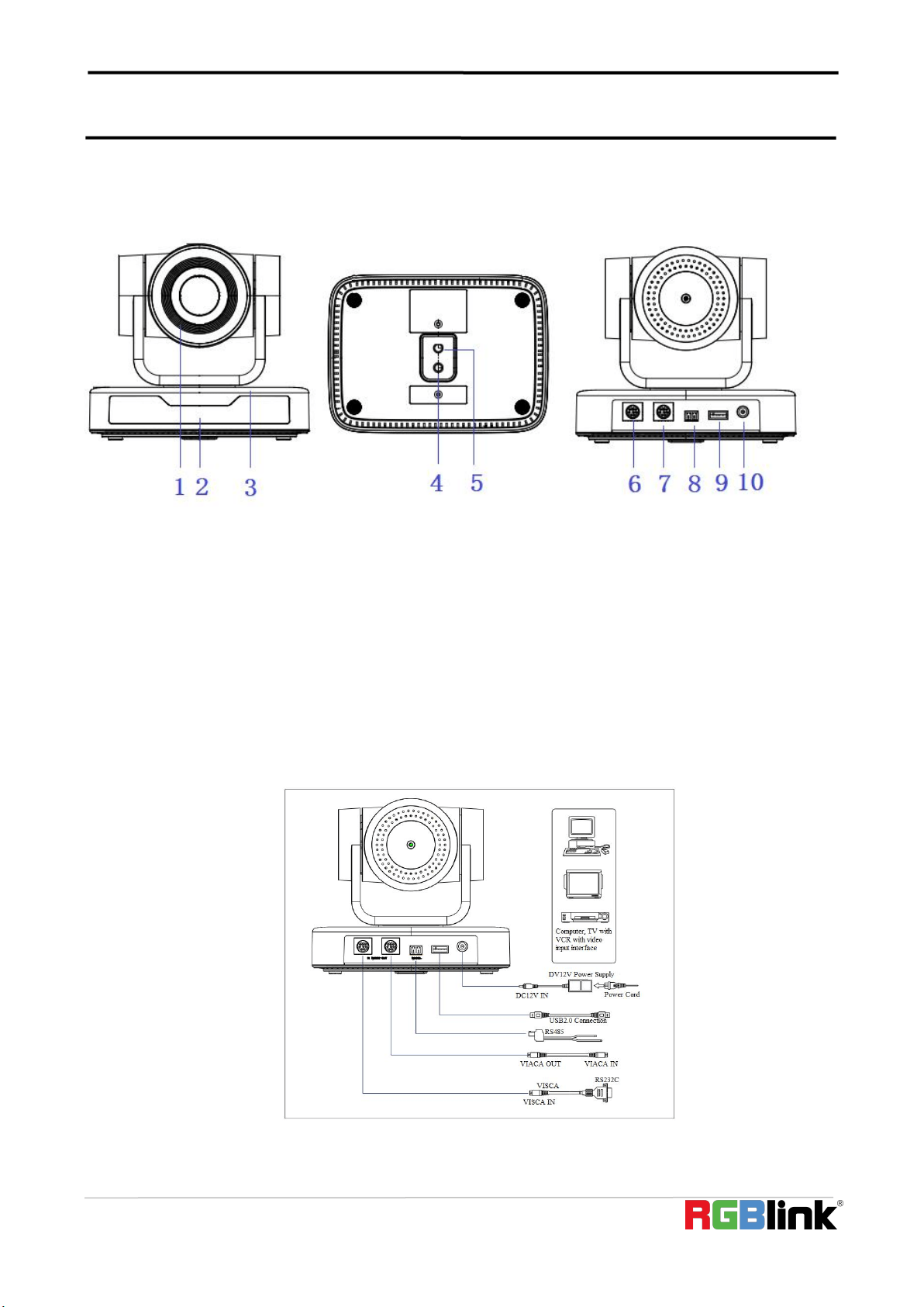
Product Interfaces
1. Camera Lens
5. Screw Hole for Tripod
9. USB 2.0 Interface
2. Remote Control Receiving
Indicator
6. RS232 Control Interface(Input)
10. DC12V Input Power Supply
Socket
3. Camera Base
7. RS232 Control Interface(Output)
4. Tripod Screw Hole
8. RS485 Input (left +, right-)
2.1.1 External Interface
Wiring Diagram
© Xiamen RGBlink Science & Technology Co., Ltd.
10
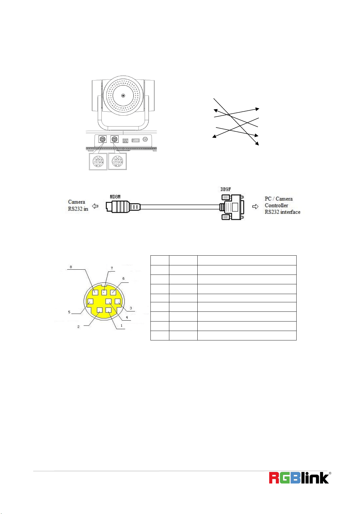
2.1.2 RS-232 Interface
1)RS-232 Interface Definition
Connection to PC or Camera Controller
Camera
WindowsDB-9
1.DTR
1.DCD
2.DSR
2.RXD
3.TXD
3.TXD
4.GND
4.DTR
5.RXD
5.GND
6.GND
6.DSR
7.IR OUT
7.RTS
8.NC
8.CTS
9.RI
2)RS-232 Mini-DIN 8-pin Port Definition
3
)
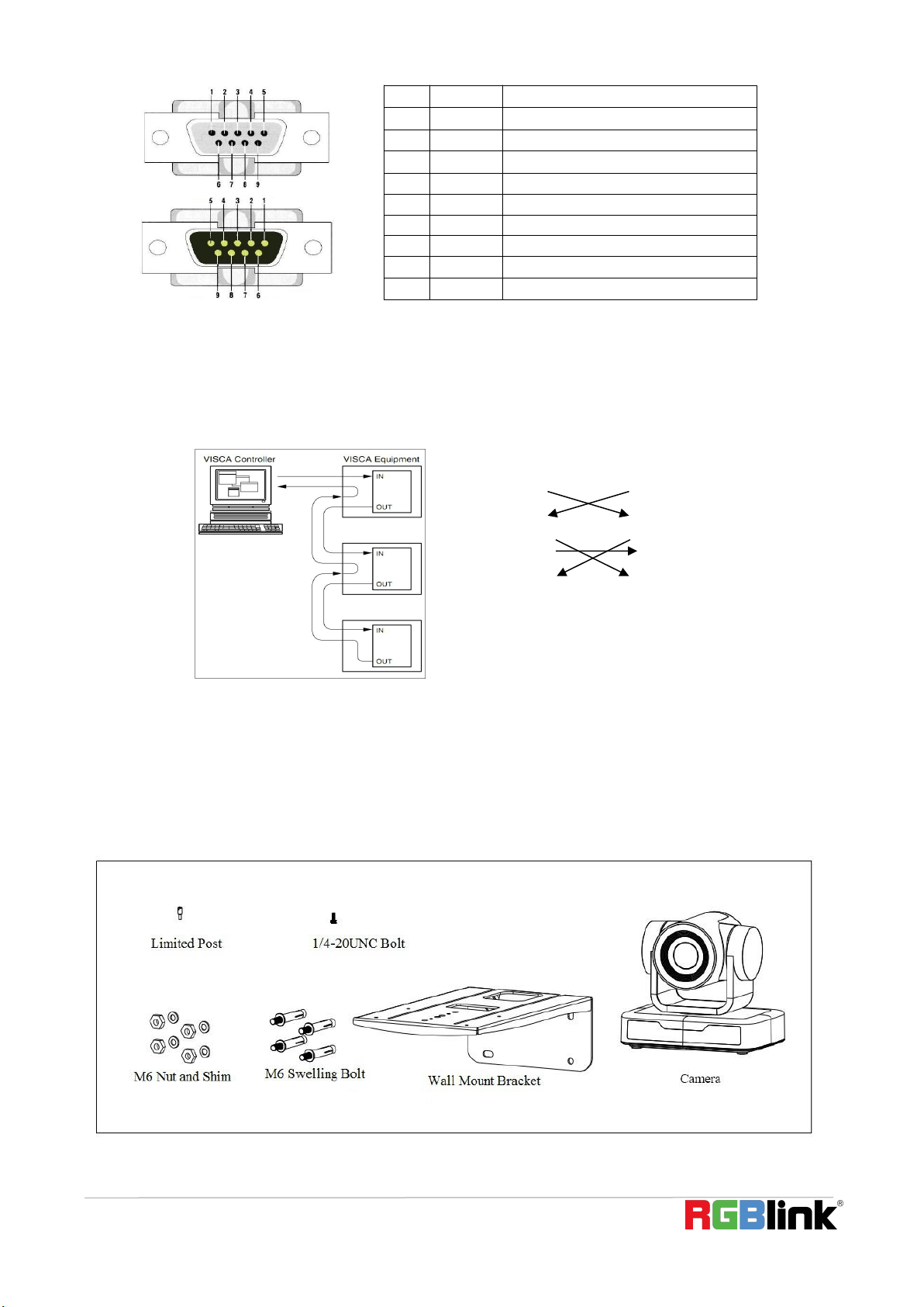
RS232(DB9) Port Definition
NO.
Port
Definition
1
DTR
Data Terminal Ready
2
DSR
Data Set Ready
3
TXD
Transmit Data
4
GND
Signal Ground
5
RXD
Receive Data
6
GND
Signal Ground
7
IR OUT
IR Commander Signal
8
NC
No Connection
© Xiamen RGBlink Science & Technology Co., Ltd.
11
4)VISCA networking as shown below
Camera cascade connection
Camera 1
Camera 2
1.DTR
1.DTR
2.DSR
2.DSR
3.TXD
3.TXD
4.GND
4.GND
5.RXD
5.RXD
6.GND
6.GND
7.IR OUT
7.OPEN
8. NC
8.OPEN
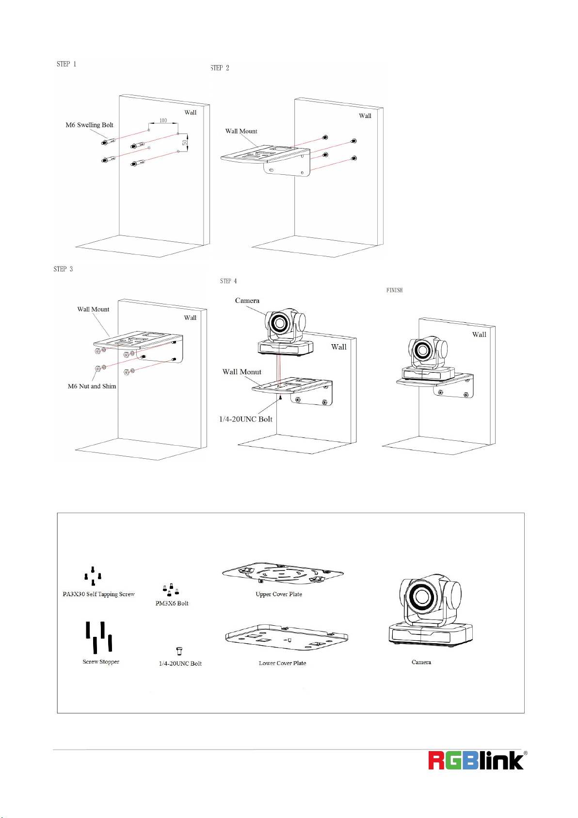
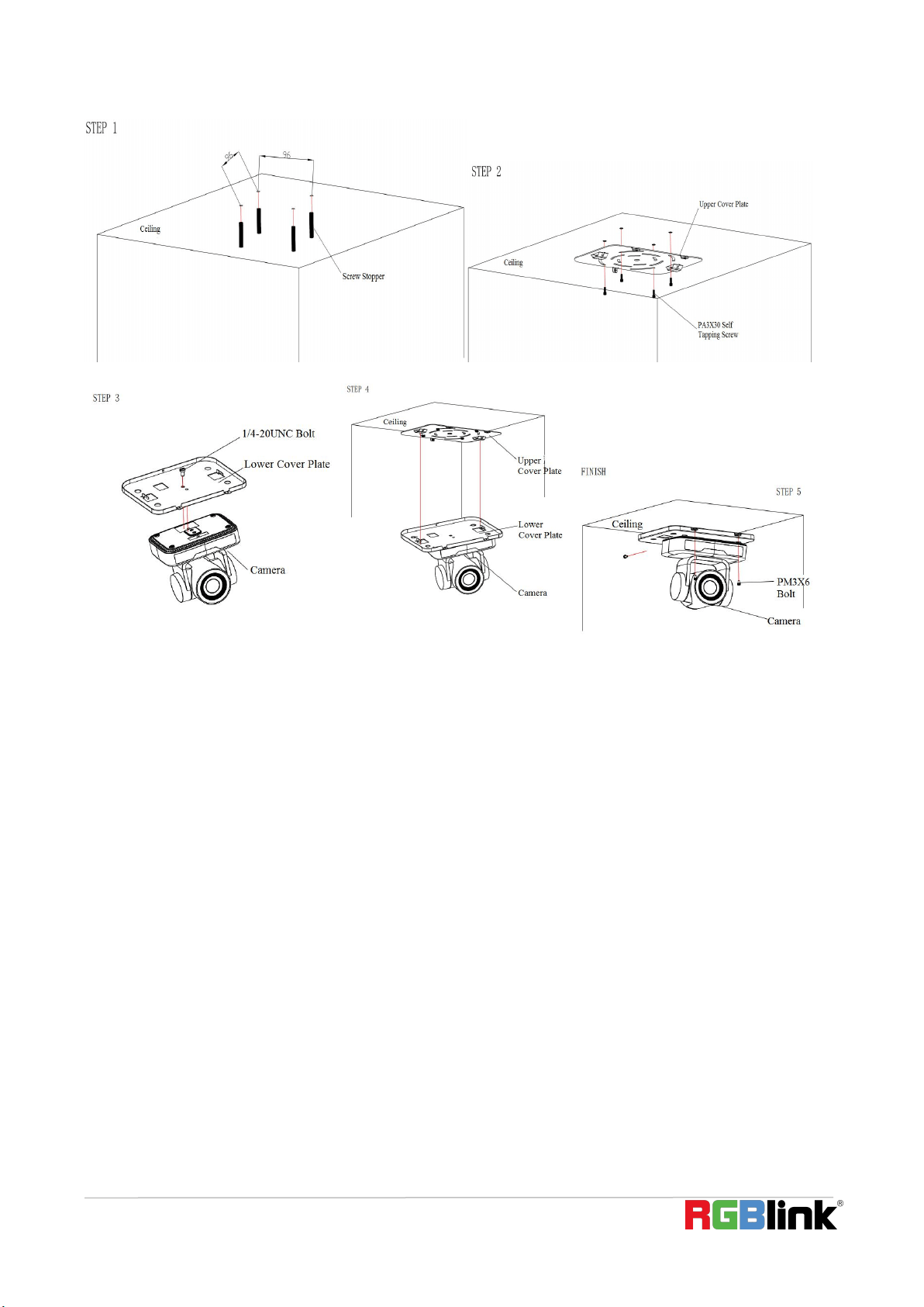
2.2 Bracket Mount
Notes: Ceiling or wall mounting brackets can only be mounted on template and concrete wall.
For safety reason, plasterboard is not recommended.
1
)
Wall Mounting:
NO.
Port
Definition
1
DCD
Data Carrier Detect
2
RXD
Receive Data
3
TXD
Transmit Data
4
DTR
Data Terminal Ready
5
GND
System Ground
6
DSR
Data Set Ready
7
RTS
Request to Send
8
CTS
Clear to Send
9
RI
Ring Indicator
© Xiamen RGBlink Science & Technology Co., Ltd.
12
2
)
Ceiling Mounting
© Xiamen RGBlink Science & Technology Co., Ltd.
13
© Xiamen RGBlink Science & Technology Co., Ltd.
14
Chapter 3 Use Your Product
3.1 Video Output
3.1.1 Power on initial configuration
The remote control receiving indicator flashes after power on, the pan-tilt turns left to the lowest left to the
lowest, and then turns to the HOME position (both the horizontal and vertical positions are in the middle), while
the movement first shrinks and then stretches. When remote control receiving indicator stops flashing, the
self-checking is completed. After power on and self-checking, the camera will automatically return to the preset 0
position if it
’
s pre-set.
3.1.2 Video Output
Connect to the video output cable: the user can refer to Figure 1.1 product interfaces.
USB2.0 output: Connect the camera with the computer USB2.0 interface (black), open the Device Manager to see
whether there is an imaging device and whether the Universal Serial Bus controllers recognize the USB2.0 device.
After properly identified, open the software, choose the imaging device, and then it will output the image.
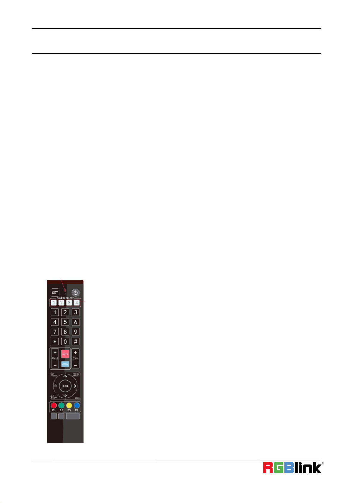
3.2 Remote Controller
3.2.1 Keys Instruction
1) In this manual, “press the key” means a click rather than a long-press, and a special
note will be given if a long-press for more than one second is required.
2) When a key-combination is required, do it in sequence. For example,
“ 【
*
】
+
【
#
】
+
【
F1
】”
means press
“【
*
】”
first and then press
“【
#
】”
and last press
“【
F1
】”
.
1. Standby Key
The camera enters standby mode if long press 3s on standby key;
Long press 3s again on the standby key, the camera will self-check again and return to
HOME position (If preset 0 position is set, the camera will return to preset 0 position).
© Xiamen RGBlink Science & Technology Co., Ltd.
15
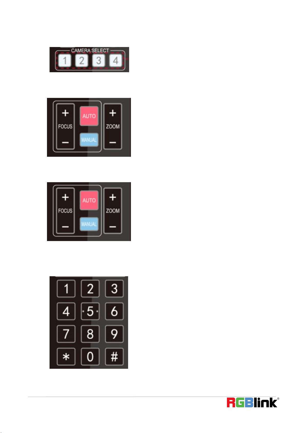
2. Camera Selection
Select the camera address to control.
3. Focus Control
Auto: auto focus mode
Manual: manual focus mode
Focus + (near):Press【FOCUS +】 key (Valid only in
manual focus mode)
Focus - (far): Press【FOCUS -】 key (Valid only in manual
focus mode)
Press and hold the keys, the action of focus will keep
continue and stop as soon as the key is released.
4. Zoom Control
ZOOM +: press
【
ZOOM +
】
key to zoom in
ZOOM - : press
【
ZOOM -
】
key to zoom out
Press and hold the keys, the action of focus will keep
continue and stop as soon as the key is released.
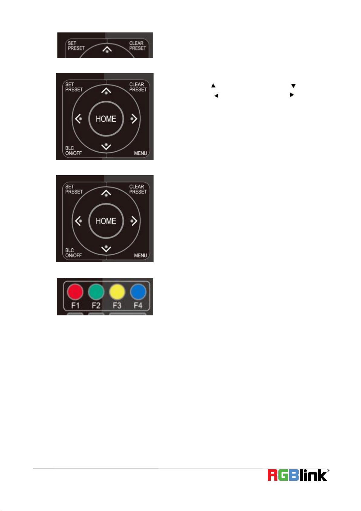
5. Set and Clear Presets
Set Preset: press
【
SET PRESET
】
button, and then press
the number key 0-9 to set preset positions.
Note: 10 presets via remote control.
Call Preset: Press a number key 0-9 directly to call a
preset position.
Clear Preset: press
【
CLEAR PRESET
】
button, and then
press the number key 0-9 to clear preset positions.
Note : press the
【
#
】
key three times continually to
clear all presets.
© Xiamen RGBlink Science & Technology Co., Ltd.
16
6. Pan/Tilt Control
Up: press Down: press
Left: press Right: press
Back to middle position: press“【HOME】”
Press and hold the up/down/left/right key, the pan/tilt
movements will keep running, from slow to fast, until it
runs to the endpoint; stop as soon as the key is
released.
7. Menu Setting
【MENU】: Open / close the OSD menu
【 HOME 】 : Camera lens back to the middle position;
Confirm button; Enter next menu
【↑】【↓】:Choose item
【←】【→】:Modify values
【BLC ON/OFF】:Turn on or off the back light
compensation
8. Camera Remote Control Address Setting
【
*
】
+
【#】
+
【
F1
】
:Camera Address No.1
【
*
】
+
【#】
+
【
F2
】
:Camera Address No. 2
【
*
】
+
【#】
+
【
F3
】
:Camera Address No. 3
【
*
】
+
【#】
+
【
F4
】
:Camera Address No. 4
3.3 Menu Setting
3.3.1 Main Menu
In normal working mode, press 【MENU】 key to display the menu, using scroll arrow to point at or highlight the
selected items.

© Xiamen RGBlink Science & Technology Co., Ltd.
17
MENU
================
(Setup)
(Camera)
(P/T/Z)
(Version)
(Restore Default)
[↑↓]Select [← →]Change Value
[Menu]Back[Home]OK
Setup: System parameter setting
Camera: Camera parameter setting
P/T/Z: Enter into sub menu
Version: Enter into sub menu
Restore Default: Enter into reset setting, select YES or NO to confirm
[↑↓] Select: For selecting menu
[← →] Change Value: For modifying parameters
[MENU] Back: Press [Menu] to return
[Home] OK: Press [Home] to confirm
3.3.2 System Setting
Move the pointer to the (Setup) in the Main Menu, click the【HOME】key and enter into the (System Setting) as
shown below,
SETUP
================
Protocol Auto
Visca Address 1
Visca Address Fix OFF
PELCO-P Address 1
PELCO-D Address 1
Baudrate 9600
Auto Filp ON
[↑↓]Select [← →]Change Value
Protocol: VISCA/Pelco-P/Pelco-D/Auto
Visca Address: VISCA=1~7 Pelco-P=1~255 Pelco-D=1~255
Baudrate: 2400/4800/9600/115200
Visca Address Fix: On/Off

© Xiamen RGBlink Science & Technology Co., Ltd.
18
Auto Filp: On/Off
3.3.3 Camera Setting
Move the pointer to the (CAMERA) in the Main Menu, click the 【HOME】key and enter the (CAMERA) as follow,
CAMERA
=================
(Exposure)
(Color)
(Image)
(Focus)
(Noise Reduction)
Style Default
[↑↓]Select [← →]Change Value
[Menu]Back [Home]OK
Exposure: Enter into Exposure setting
Color: Enter into color setting
Image: Enter into image setting
Focus: Enter into focus setting
Noise Reduction: Enter into noise reduction
1)Exposure Setting
Move the pointer to the (EXPOSURE) in the Main Menu, click the【HOME】key and enter into the (Exposure sub
menu) as shown below,
EXPOSURE
=================
Mode Auto
EV OFF
BLC OFF
Flicker 50Hz
G.Limit 3
DRC 2
[↑↓]Select [← →]Change Value
[Menu]Back
Mode: Auto, Manual, Shutter priority, Iris priority and Brightness priority.
EV: On/Off (only available in auto mode)
Compensation Level: -7~7 (only available in auto mode when EV is ON)
BLC: ON/OFF for options (only available in auto mode)
Dynamic Range: 1~8, close

© Xiamen RGBlink Science & Technology Co., Ltd.
19
Anti-Flicker: OFF/50Hz/60Hz for options (only available in Auto/Iris priority/Brightness priority modes)
Gain limit: 0~15 (only available in Auto/ Iris priority /Brightness priority mode)
WDR: Off, 1~8
ShutterPriority:1/25,1/30,1/50,1/60,1/90,1/100,1/120,1/180,1/250,1/350,1/500,1/1000,1/2000,1/3000,1/4000,1
/6000, 1/10000 (only available in Manual and Shutter priority mode)
IRIS Priority: OFF, F11.0, F9.6, F8.0, F6.8, F5.6, F4.8, F4.0, F3.4, F2.8, F2.4, F2.0, F1.8(only available in Manual and
Iris priority mode)
Brightness: 0~23 (only available in Brightness priority mode)
2
)
Color
Move the pointer to the (COLOR) in the Main Menu, click the【HOME】and enter the (COLOR sub menu) as follow,
COLOR
================
WB Mode Auto
RG Tuning -10
BG Tuning -10
Saturation 100%
Hue 7
AWB Sensitivity High
[↑↓]Select [← →]Change Value
[Menu]Back
WB Mode: Auto, Manual, One Push, 3000K, 3500K, 4000K, 4500K, 5000K, 5500K, 6000K, 6500K,7000K
Saturation: 60%,70%,80%,90%,100%,110%,120%,130%,140%,150%,160%,170%,180%,190%,200%
Red fine-tuning: -10~10 (only available in automatic mode)
Blue fine-tunable: -10~10 (only available in automatic mode)
RED GAIN: 0~255(only available in Manual mode)
BLUE GAIN: 0~255(only available in Manual mode)
AWB Sensitivity: high/middle/low
Chroma: 0~14
3) Image
Move the pointer to the (IMAGE) in the Menu, click the【HOME】and enter into the (IMAGE sub menu) as follow,

© Xiamen RGBlink Science & Technology Co., Ltd.
20
IMAGE
================
Brightness 7
Contrast 8
Sharpness 3
Flip-H OFF
Flip-V OFF
B&W-Mode Color
Gamma Default
DCI Close
Low-Light Mode OFF
[↑↓]Select [← →]Change Value
[Menu]Back
Brightness: 0~14
Contrast: 0~14
Sharpness: 0~15
Flip-H: On/Off
Flip-V: On/Off
B&W Mode: color, black/white
Gamma: Default/0.45/0.50/0.5/0.63
DCI: Dynamic Contrast: Off/1
~
8
Minimum Illumination: On/Off
4)Focus
Move the pointer to the (FOCUS) in the Menu, click the
【
HOME
】
and enter the (FOCUS) as follow,
FOCUS
=================
Focus Mode Auto
AF-Zone All
AF-Sensitivity Low
[↑↓]Select [← →]Change Value
[Menu]Back
Focus Mode: Auto/manual
AF-Zone: Up/middle/down
AF-Sensitivity: High/middle/low
5)Noise Reduction
Move the pointer to the (NOISE REDUCTION) in the Menu, click the
【
HOME
】
and enter the (NOISE REDUCTION) as
follow,

© Xiamen RGBlink Science & Technology Co., Ltd.
21
NOISE REDUCTION
=================
NR-2D 4
NR-3D 2
Dynamic Hot Pixel OFF
[↑↓]Select [← →]Change Value
[Menu]Back
2D Noise Reduction: Auto, close, 1~7
3D Noise Reduction: Close, 1~8
Dynamic Hot Pixel: Close, 1~5
3.3.4 P/T/Z
Move the pointer to the (P/T/Z) in the Main Menu, click the
【
HOME
】
and enter the (P/T/Z) as follow,
P/T/Z
================
Speed by zoom ON
Zoom speed 8
Acc Curve Slow
[↑↓]Select [← →]Change Value
[Menu]Back
Depth of Field: Only effective for the remote controller, On/ Off;
(When zooming in, the PT control speed by remoter will become slow)
Zoom Speed: Set the zoom speed for the remote controller, 1~8
Image Freezing: On/Off
Accelerating Curve: Fast/Slow
3.3.5 Version
Move the pointer to the (VERSION) in the Main Menu, click the
【
HOME
】
and enter the (VERSION) as follow,

© Xiamen RGBlink Science & Technology Co., Ltd.
22
VERSION
=================
MCU Version 3.1.0 2019-09-26
Camera Version 1.0.5 2019-09-27
AF Version 1.0.0 2019-09-07
[↑↓]Select [← →]Change Value
[Menu]Back [Home]OK
MCU Version: Display MCU version information
Camera Version: Display camera version information
AF Version: Display the focus version information
3.3.6 Restore Default
Move the pointer to the (RESTORE DEFAULT) in the Main Menu, click the【HOME】and enter the (RESTORE DEFAULT)
as follow,
RESTORE DEFAULT
=================
Restore Default? NO
[↑↓]Select [← →]Change Value
[Menu]Back [Home]OK
Restore default: YES/NO. Color style and video format cannot be restored to factory default
Note: If the address of former remoter is not 1 but another one from 2, 3, 4, the corresponding camera address
will restore to 1 when all parameters or system parameters are restored. User should change the remoter
address to be 1 (press No.1 according to the camera so to get normal operation).

© Xiamen RGBlink Science & Technology Co., Ltd.
23
Chapter 4 Ordering Codes
4.1 Product
981-0011-12-0 RGB10X-USB-BK 10X PTZ Camera

© Xiamen RGBlink Science & Technology Co., Ltd.
24
Chapter 5 Support
5.1 Contact us

© Xiamen RGBlink Science & Technology Co., Ltd.
27
5.2 Camera Maintenance and Troubleshooting
5.2.1 Camera Maintenance
1) Please power off the camera and disconnect the power adapter and socket, if it’s not used for a long run.
2) Use soft cloth or tissue to clean the camera cover.
3) Wipe it with a soft, dry cloth when cleaning the camera lens. Wipe it gently with a mild detergent if needed. Do
not use strong or corrosive detergents to avoid scratching the lens and affecting the video quality.
5.2 Troubleshooting
1) No video output
a. Check whether the camera power supply is connected, the voltage is normal, the power indicator is lit.
b. Whether the machine could do self-check after restarted.
c. Check whether the bottom of the DIP switch is the normal operating mode
d. Check whether the video output cable or video display is normal
2) No image sometimes
a. Check whether the video output cable or video display is normal
3) Video dithering when zoom-in or zoom-out
a. Check whether the camera installation position is solid
b. Whether there is shaking machine or objects around the camera
4) Remote control not works
a. Remote control address is set to 1 (if the machine is set back to the factory defaults, remote control addresses
need to be back to 1 too)
b. Check whether the battery is installed on the remote controller or low.
c, Check the camera working mode is the normal operating moded. Check the menu whether is closed, camera
control through remote controller is only available after exiting the menu. If video output from LAN, menu will
not be displayed, menu will automatically exists 30s later, and then it can be controlled by remote controller.
5) Serial port not works
a. Check whether the camera serial device protocol, baud rate, address is consistent
b. Check whether the control cable is connected properly
c. Check whether the camera working mode is the normal operating mode
© Xiamen RGBlink Science & Technology Co., Ltd.
28
Chapter 6 Appendix
The camera could be controlled through RS232/RS485 interface; RS232C serial parameter are as follows:
Baud rate: 2400/4800/9600/115200 bits / sec; Start bit: 1; data bits: 8; Stop bit: 1; Parity: None.
After power on, the camera first goes left, then back to the middle position. Self-test is finished after the zoom
moved to the farthest and then back to the nearest position. If the camera saved 0 preset before, it will be back
to that position after initialization. At this point, the user can control the camera by the serial commands.
6.1 VISCA Protocol List
6.1.1 Camera Return Command
Ack/Completion Message
Command packet
Note
ACK
z0 41 FF
Returned when the command is accepted.
Completion
z0 51 FF
Returned when the command has been executed.
z = camera address + 8
Error Messages
Command packet
Note
Syntax Error
z0 60 02 FF
Returned when the command format is different or when a
command with illegal command parameters is accepted
Command Not Executable
z0 61 41 FF
Returned when a command cannot be executed due to current
conditions. For example, when commands controlling the focus
manually are received during auto focus.
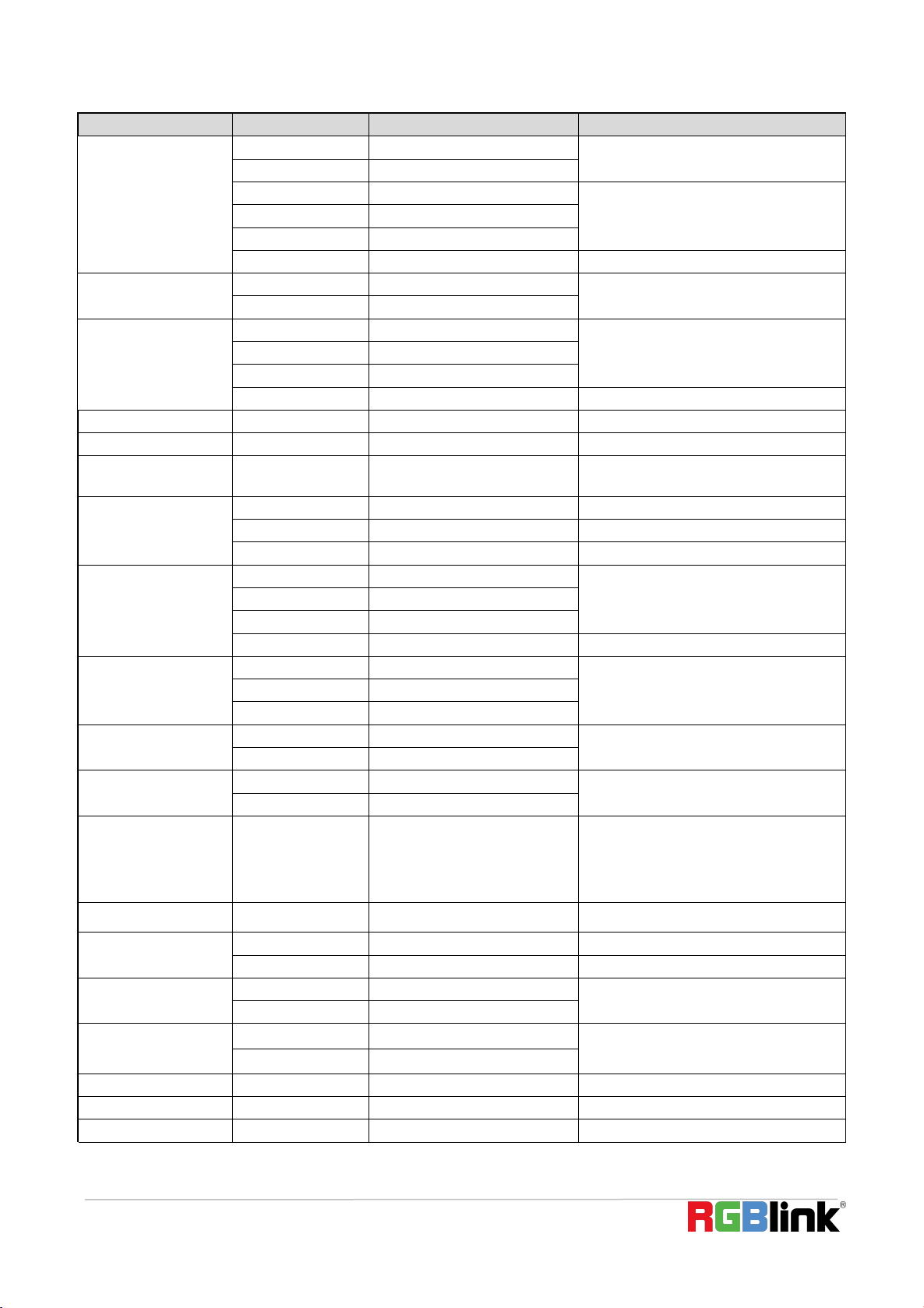
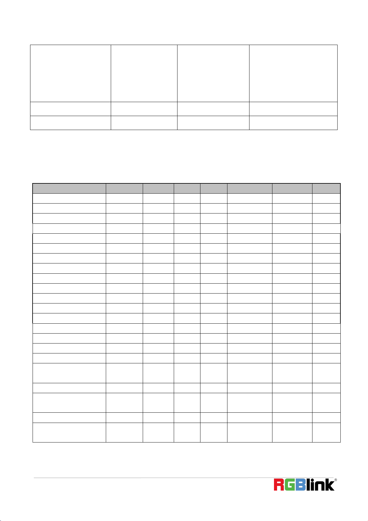
6.1.2 Camera Control Command
Command
Function
Command packet
Note
AddressSet
Broadcast
88 30 0p FF
p:Address setting
IF_Clear
Broadcast
88 01 00 01 FF
I/F Clear
CommandCancel
8x 21 FF
CAM_Power
On
8x 01 04 00 02 FF
Power ON/OFF
Off
8x 01 04 00 03 FF
CAM_Zoom
Stop
8x 01 04 07 00 FF
Tele(Standard)
8x 01 04 07 02 FF
Wide(Standard)
8x 01 04 07 03 FF
Tele(Variable)
8x 01 04 07 2p FF
p = 0(low) - F(high)
Wide(Variable)
8x 01 04 07 3p FF
Direct
8x 01 04 47 0p 0q 0r 0s FF
pqrs: Zoom Position
CAM _Focus
Stop
8x 01 04 08 00 FF
Far(Standard)
8x 01 04 08 02 FF
Near(Standard)
8x 01 04 08 03 FF
Far(Variable)
8x 01 04 08 2p FF
p = 0(low) - F(high)
© Xiamen RGBlink Science & Technology Co., Ltd.
29
Command
Function
Command packet
Note
Near (Variable)
8x 01 04 08 3p FF
Direct
8x 01 04 48 0p 0q 0r 0s FF
pqrs: Focus Position
Auto Focus
8x 01 04 38 02 FF
Manual Focus
8x 01 04 38 03 FF
One Push mode
8x 01 04 38 04 FF
CAM _Zoom Focus
Direct
8x 01 04 47 0p 0q 0r 0s
0t 0u 0v 0w FF
pqrs: Zoom Position
tuvw: Focus Position
CAM_WB
Auto
8x 01 04 35 00 FF
3000K
8x 01 04 35 01 FF
4000k
8x 01 04 35 02 FF
One Push mode
8x 01 04 35 03 FF
5000k
8x 01 04 35 04 FF
Manual
8x 01 04 35 05 FF
6500k
8x 01 04 35 06 FF
3500K
8x 01 04 35 07 FF
4500K
8x 01 04 35 08 FF
5500K
8x 01 04 35 09 FF
6000K
8x 01 04 35 0A FF
7000K
8x 01 04 35 0B FF
CAM _RGain
Reset
8x 01 04 03 00 FF
Manual Control of R Gain
Up
8x 01 04 03 02 FF
Down
8x 01 04 03 03 FF
Direct
8x 01 04 43 00 00 0p 0q FF
pq: R Gain
CAM_ Bgain
Reset
8x 01 04 04 00 FF
Manual Control of B Gain
Up
8x 01 04 04 02 FF
Down
8x 01 04 04 03 FF
Direct
8x 01 04 44 00 00 0p 0q FF
pq: B Gain
CAM_AE
Full Auto
8x 01 04 39 00 FF
Automatic Exposure mode
Manual
8x 01 04 39 03 FF
Manual Control mode
Shutter priority
8x 01 04 39 0A FF
Shutter Priority Automatic Exposure mode
Iris priority
8x 01 04 39 0B FF
Iris Priority Automatic Exposure mode
Bright
8x 01 04 39 0D FF
Bright mode
CAM_Shutter
Reset
8x 01 04 0A 00 FF
Shutter Setting
Up
8x 01 04 0A 02 FF
Down
8x 01 04 0A 03 FF
Direct
8x 01 04 4A 00 00 0p 0q FF
pq: Shutter Position
CAM_Iris
Reset
8x 01 04 0B 00 FF
Iris Setting
Up
8x 01 04 0B 02 FF
Down
8x 01 04 0B 03 FF
Direct
8x 01 04 4B 00 00 0p 0q FF
pq: Iris Position
CAM_Gain Limit
Gain Limit
8x 01 04 2C 0p FF
p: Gain Positon
CAM_Bright
Reset
8x 01 04 0D 00 FF
Bright Setting
Up
8x 01 04 0D 02 FF
Down
8x 01 04 0D 03 FF
Direct
8x 01 04 4D 00 00 0p 0q FF
pq: Bright Positon
© Xiamen RGBlink Science & Technology Co., Ltd.
30
Command
Function
Command packet
Note
CAM_ExpComp
On
8x 01 04 3E 02 FF
Exposure Compensation ON/OFF
Off
8x 01 04 3E 03 FF
Reset
8x 01 04 0E 00 FF
Exposure Compensation Amount Setting
Up
8x 01 04 0E 02 FF
Down
8x 01 04 0E 03 FF
Direct
8x 01 04 4E 00 00 0p 0q FF
pq: ExpComp Position
CAM_Back Light
On
8x 01 04 33 02 FF
Back Light
Compensation
Off
8x 01 04 33 03 FF
CAM_WDRStrength
Reset
8x 01 04 21 00 FF
WDR Level Setting
Up
8x 01 04 21 02 FF
Down
8x 01 04 21 03 FF
Direct
8x 01 04 51 00 00 00 0p FF
p: WDR Level Positon
CAM_NR(2D)
8x 01 04 53 0p FF
P=0-7 0:OFF
CAM_NR(3D)
8x 01 04 54 0p FF
P=0-8 0:OFF
CAM_Gamma
8x 01 04 5B 0p FF
p = 0 – 4 0:Default 1:0.45 2:0.50
3:0.55 4:0.63
CAM_Flicker
OFF
8x 01 04 23 00 FF
OFF
50HZ
8x 01 04 23 01 FF
50HZ
60HZ
8x 01 04 23 02 FF
60HZ
CAM_Aperture
Reset
8x 01 04 02 00 FF
Aperture Control
Up
8x 01 04 02 02 FF
Down
8x 01 04 02 03 FF
Direct
8x 01 04 42 00 00 0p 0q FF
pq: Aperture Gain
CAM_Memory
Reset
8x 01 04 3F 00 pq FF
pq: Memory Number(=0 to 254)
Corresponds to 0 to 9 on the Remote
Commander
Set
8x 01 04 3F 01 pq FF
Recall
8x 01 04 3F 02 pq FF
CAM_LR_Reverse
On
8x 01 04 61 02 FF
Image Flip Horizontal ON/OFF
Off
8x 01 04 61 03 FF
CAM_PictureFlip
On
8x 01 04 66 02 FF
Image Flip Vertical ON/OFF
Off
8x 01 04 66 03 FF
CAM_ColorSaturation
Direct
8x 01 04 49 00 00 00 0p FF
P=0-E
0:60% 1:70% 2:80% 3:90% 4:100%
5:110% 6:120% 7:130% 8:140%
9:150% 10:160% 11:160% 12:180%
13:190% 14:200%
CAM_IDWrite
8x 01 04 22 0p 0q 0r 0s FF
pqrs: Camera ID (=0000 to FFFF)
SYS_Menu
ON
8x 01 04 06 06 02 FF
Turn on the menu screen
OFF
8x 01 04 06 06 03 FF
Turn off the menu screen
IR_Receive
ON
8x 01 06 08 02 FF
IR(remote commander)receive On/Off
OFF
8x 01 06 08 03 FF
IR_ReceiveReturn
On
8x 01 7D 01 03 00 00 FF
IR(remote commander)receive message via
the VISCA communication ON/OFF
Off
8x 01 7D 01 13 00 00 FF
CAM_SettingReset
Reset
8x 01 04 A0 10 FF
Reset Factory Setting
CAM_Brightness
Direct
8x 01 04 A1 00 00 0p 0q FF
pq: Brightness Position
CAM_Contrast
Direct
8x 01 04 A2 00 00 0p 0q FF
pq: Contrast Position
© Xiamen RGBlink Science & Technology Co., Ltd.
31
Command
Function
Command packet
Note
CAM_Flip
OFF
8x 01 04 A4 00 FF
Single Command For Video Flip
Flip-H
8x 01 04 A4 01 FF
Flip-V
8x 01 04 A4 02 FF
Flip-HV
8x 01 04 A4 03 FF
CAM_VideoSystem
Set camera video
system
8x 01 06 35 00 0p FF
P: 0~E Video format
0:1080P60 8:720P30
1:1080P50 9:720P25
2:1080i60 A:1080P59.94
3:1080i50 B:1080i59.94
4:720P60 C:720P59.94
5:720P50 D:1080P29.97
6:1080P30 E:720P29.97
7:1080P25
Pan_tiltDrive
Up
8x 01 06 01 VV WW 03 01 FF
VV: Pan speed 0x01 (low speed) to 0x18
(high speed)
WW: Tilt speed 0x01 (low speed) to 0x14
(high speed)
YYYY: Pan Position
ZZZZ: Tilt Position
Down
8x 01 06 01 VV WW 03 02 FF
Left
8x 01 06 01 VV WW 01 03 FF
Right
8x 01 06 01 VV WW 02 03 FF
Upleft
8x 01 06 01 VV WW 01 01 FF
Upright
8x 01 06 01 VV WW 02 01 FF
DownLeft
8x 01 06 01 VV WW 01 02 FF
DownRight
8x 01 06 01 VV WW 02 02 FF
Stop
8x 01 06 01 VV WW 03 03 FF
AbsolutePosition
8x 01 06 02 VV WW
0Y 0Y 0Y 0Y 0Z 0Z 0Z 0Z FF
RelativePosition
8x 01 06 03 VV WW
0Y 0Y 0Y 0Y 0Z 0Z 0Z 0Z FF
Home
8x 01 06 04 FF
Reset
8x 01 06 05 FF
Pan-tiltLimitSet
Set
8x 01 06 07 00 0W
0Y 0Y 0Y 0Y 0Z 0Z 0Z 0Z FF
W:1 UpRight 0:DownLeft
YYYY: Pan Limit Position(TBD)
ZZZZ: Tilt Limit Position(TBD)
Clear
8x 01 06 07 01 0W
07 0F 0F 0F 07 0F 0F 0F FF
6.1.3 Inquiry Command
Command
Command Packet
Return Packet
Note
CAM_PowerInq
8x 09 04 00 FF
y0 50 02 FF
On
y0 50 03 FF
Off(Standby)
CAM_ZoomPosInq
8x 09 04 47 FF
y0 50 0p 0q 0r 0s FF
pqrs: Zoom Position
CAM_FocusAFModeInq
8x 09 04 38 FF
y0 50 02 FF
Auto Focus
y0 50 03 FF
Manual Focus
y0 50 04 FF
One Push mode
CAM_FocusPosInq
8x 09 04 48 FF
y0 50 0p 0q 0r 0s FF
pqrs: Focus Position
CAM_WBModeInq
8x 09 04 35 FF
y0 50 00 FF
Auto
y0 50 01 FF
3000K
y0 50 02 FF
4000K
y0 50 03 FF
One Push Mode
y0 50 04 FF
5000K
y0 50 05 FF
Manual
y0 50 00 FF
6500K
y0 50 06 FF
6500K
y0 50 07 FF
3500K
y0 50 08 FF
4500K
y0 50 09 FF
5500K
© Xiamen RGBlink Science & Technology Co., Ltd.
32
y0 50 0A FF
6000K
CAM_RGainInq
8x 09 04 43 FF
y0 50 0B FF
7000K
CAM_BGainInq
8x 09 04 44 FF
y0 50 00 00 0p 0q FF
pq: B Gain
CAM_AEModeInq
8x 09 04 39 FF
y0 50 00 FF
Full Auto
y0 50 03 FF
Manual
y0 50 0A FF
Shutter priority
y0 50 0B FF
Iris priority
y0 50 0D FF
Bright
CAM_ShutterPosInq
8x 09 04 4A FF
y0 50 00 00 0p 0q FF
pq: Shutter Position
CAM_IrisPosInq
8x 09 04 4B FF
y0 50 00 00 0p 0q FF
pq: Iris Position
CAM_Gain LimitInq
8x 09 04 2C FF
y0 50 0p FF
p: Gain Positon
CAM_ BrightPosiInq
8x 09 04 4D FF
y0 50 00 00 0p 0q FF
pq: Bright Position
CAM_ExpCompModeInq
8x 09 04 3E FF
y0 50 02 FF
On
y0 50 03 FF
Off
CAM_ExpCompPosInq
8x 09 04 4E FF
y0 50 00 00 0p 0q FF
pq: ExpComp Position
CAM_BacklightModeInq
8x 09 04 33 FF
y0 50 02 FF
On
y0 50 03 FF
Off
CAM_WDRStrengthInq
8x 09 04 51 FF
y0 50 00 00 00 0p FF
p: WDR Strength
CAM_NRLevel(2D) Inq
8x 09 04 53 FF
y0 50 0p FF
P: 2DNRLevel
CAM_NRLevel(3D) Inq
8x 09 04 54 FF
y0 50 0p FF
P:3D NRLevel
CAM_FlickerModeInq
8x 09 04 55 FF
y0 50 0p FF
p: Flicker Settings(0: OFF, 1: 50Hz,
2:60Hz)
CAM_ApertureInq
8x 09 04 42 FF
y0 50 00 00 0p 0q FF
pq: Aperture Gain
CAM_PictureEffectModeInq
8x 09 04 63 FF
y0 50 00 FF
Off
y0 50 04 FF
B&W
CAM_MemoryInq
8x 09 04 3F FF
y0 50 0p FF
p: Memory number last operated.
SYS_MenuModeInq
8x 09 06 06 FF
y0 50 02 FF
On
y0 50 03 FF
Off
CAM_LR_ReverseInq
8x 09 04 61 FF
y0 50 02 FF
On
y0 50 03 FF
Off
CAM_PictureFlipInq
8x 09 04 66 FF
y0 50 02 FF
On
y0 50 03 FF
Off
CAM_ColorSaturationInq
8x 09 04 49 FF
y0 50 00 00 00 0p FF
p: Color Gain setting 0h (60%) to Eh
(130%)
CAM_IDInq
8x 09 04 22 FF
y0 50 0p FF
p: Gamma ID
IR_ReceiveInq
8x 09 06 08 FF
y0 50 02 FF
On
y0 50 03 FF
Off
IR_ReceiveReturn
y0 07 7D 01 04 00 FF
Power ON/OFF
y0 07 7D 01 04 07 FF
Zoom tele/wide
y0 07 7D 01 04 38 FF
AF ON/OFF
y0 07 7D 01 04 33 FF
Camera _Backlight
y0 07 7D 01 04 3F FF
Camera _Memery
y0 07 7D 01 06 01 FF
Pan_titleDriver
CAM_BrightnessInq
8x 09 04 A1 FF
y0 50 00 00 0p 0q FF
pq: Brightness Position
CAM_ContrastInq
8x 09 04 A2 FF
y0 50 00 00 0p 0q FF
pq: Contrast Position
CAM_FlipInq
8x 09 04 A4 FF
y0 50 00 FF
Off
y0 50 01 FF
Flip-H
y0 50 02 FF
Flip-V
y0 50 03 FF
Flip-HV
CAM_GammaInq
8x 09 04 5B FF
y0 50 0p FF
p: Gamma setting
CAM_VersionInq
8x 09 00 02 FF
y0 50 ab cd
mn pq rs tu vw FF
ab cd : vender ID ( 0220 )
mn pq : model ID ST ( 0510 ) 、
U2( 0512 )、U3 ( 0513 )
rs tu : ARM Version
vw : reserve
VideoSystemInq
8x 09 06 23 FF
y0 50 0p FF
P: 0~E Video format
0:1080P60
8:720P30
© Xiamen RGBlink Science & Technology Co., Ltd.
33
1:1080P50
9:720P25
2:1080i60 A:1080P59.94
3:1080i50 B:1080i59.94
4:720P60 C:720P59.94
5:720P50 D:1080P29.97
6:1080P30 E:720P29.97
7:1080P25
Pan-tiltMaxSpeedInq
8x 09 06 11 FF
y0 50 ww zz FF
ww: Pan Max Speed zz: Tilt
Max Speed
Pan-tiltPosInq
8x 09 06 12 FF
y0 50 0w 0w 0w 0w
0z 0z 0z 0z FF
wwww: Pan Position zzzz: Tilt
Position
Note:[X] in the above table indicates the camera address to be operated,
【
y
】
=
【
x + 8
】
.
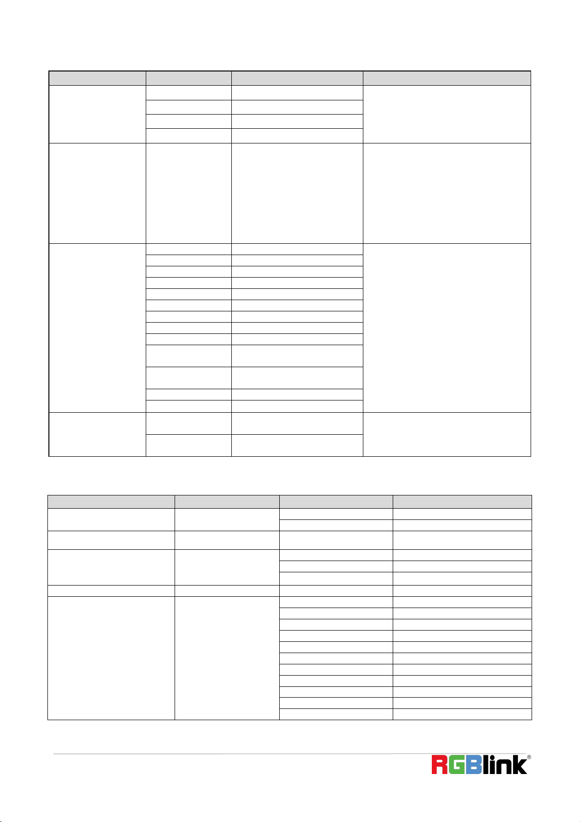
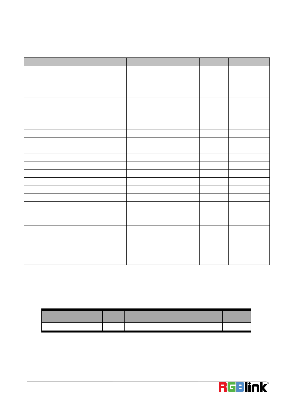
6.2 Pelco-D Protocol Command List
Function
Byte1
Byte2
Byte3
Byte4
Byte5
Byte6
Byte7
Up
0xFF
Address
0x00
0x08
Pan Speed
Tilt Speed
SUM
Down
0xFF
Address
0x00
0x10
Pan Speed
Tilt Speed
SUM
Left
0xFF
Address
0x00
0x04
Pan Speed
Tilt Speed
SUM
Right
0xFF
Address
0x00
0x02
Pan Speed
Tilt Speed
SUM
Upleft
0xFF
Address
0x00
0x0C
Pan Speed
Tilt Speed
SUM
Upright
0xFF
Address
0x00
0x0A
Pan Speed
Tilt Speed
SUM
DownLeft
0xFF
Address
0x00
0x14
Pan Speed
Tilt Speed
SUM
DownRight
0xFF
Address
0x00
0x12
Pan Speed
Tilt Speed
SUM
Zoom In
0xFF
Address
0x00
0x20
0x00
0x00
SUM
Zoom Out
0xFF
Address
0x00
0x40
0x00
0x00
SUM
Focus Far
0xFF
Address
0x00
0x80
0x00
0x00
SUM
Focus Near
0xFF
Address
0x01
0x00
0x00
0x00
SUM
Stop
0xFF
Address
0x00
0x00
0x00
0x00
SUM
Set Preset
0xFF
Address
0x00
0x03
0x00
Preset ID
SUM
Clear Preset
0xFF
Address
0x00
0x05
0x00
Preset ID
SUM
Call Preset
0xFF
Address
0x00
0x07
0x00
Preset ID
SUM
Query Pan Position
0xFF
Address
0x00
0x51
0x00
0x00
SUM
Query Pan Position Response
0xFF
Address
0x00
0x59
Value High Byte
Value Low
Byte
SUM
Query Tilt Position
0xFF
Address
0x00
0x53
0x00
0x00
SUM
Query Tilt Position Response
0xFF
Address
0x00
0x5B
Value High Byte
Value Low
Byte
SUM
Query Zoom Position
0xFF
Address
0x00
0x55
0x00
0x00
SUM
Query Zoom Position
Response
0xFF
Address
0x00
0x5D
Value High Byte
Value Low
Byte
SUM
© Xiamen RGBlink Science & Technology Co., Ltd.
34
6.3 Pelco-P Protocol Command List
Function
Byte1
Byte2
Byte3
Byte4
Byte5
Byte6
Byte7
Byte8
Up
0xA0
Address
0x00
0x08
Pan Speed
Tilt Speed
0xAF
XOR
Down
0xA0
Address
0x00
0x10
Pan Speed
Tilt Speed
0xAF
XOR
Left
0xA0
Address
0x00
0x04
Pan Speed
Tilt Speed
0xAF
XOR
Right
0xA0
Address
0x00
0x02
Pan Speed
Tilt Speed
0xAF
XOR
Upleft
0xA0
Address
0x00
0x0C
Pan Speed
Tilt Speed
0xAF
XOR
Upright
0xA0
Address
0x00
0x0A
Pan Speed
Tilt Speed
0xAF
XOR
DownLeft
0xA0
Address
0x00
0x14
Pan Speed
Tilt Speed
0xAF
XOR
DownRight
0xA0
Address
0x00
0x12
Pan Speed
Tilt Speed
0xAF
XOR
Zoom In
0xA0
Address
0x00
0x20
0x00
0x00
0xAF
XOR
Zoom Out
0xA0
Address
0x00
0x40
0x00
0x00
0xAF
XOR
Stop
0xA0
Address
0x00
0x00
0x00
0x00
0xAF
XOR
Focus Far
0xA0
Address
0x01
0x00
0x00
0x00
0xAF
XOR
Focus Near
0xA0
Address
0x02
0x00
0x00
0x00
0xAF
XOR
Set Preset
0xA0
Address
0x00
0x03
0x00
Preset ID
0xAF
XOR
Clear Preset
0xA0
Address
0x00
0x05
0x00
Preset ID
0xAF
XOR
Call Preset
0xA0
Address
0x00
0x07
0x00
Preset ID
0xAF
XOR
Query Pan Position
0xA0
Address
0x00
0x51
0x00
0x00
0xAF
XOR
Query Pan Position
Response
0xA0
Address
0x00
0x59
Value High Byte
Value Low
Byte
0xAF
XOR
Query Tilt Position
0xA0
Address
0x00
0x53
0x00
0x00
0xAF
XOR
Query Tilt Position
Response
0xA0
Address
0x00
0x5B
Value High Byte
Value Low
Byte
0xAF
XOR
Query Zoom Position
0xA0
Address
0x00
0x55
0x00
0x00
0xAF
XOR
Query Zoom Position
Response
0xA0
Address
0x00
0x5D
Value High Byte
Value Low
Byte
0xAF
XOR
6.4 Revision History
The table below lists the changes to the User Manual.
All information herein is
©
Xiamen RGBlink Science & Technology Co Ltd. excepting where noted.
RGBlink
®
is a registered trademark of Xiamen RGBlink Science & Technology Co Ltd. While all efforts are ma
de for accuracy at time of printing, we reserve the right to alter, vary or otherwise make change without not
ice. E&OM excepted.
Format
Time
ECO#
Description
Principle
V1.0
2021-09-01
0000#
Release
Sylvia