Loading ...
Loading ...
Loading ...
Page 32
7
Outdoor Unit Installation Instructions
Outdoor Unit
Installation
BEFORE PERFORMING
ANY ELECTRICAL WORK,
READ THESE REGULATIONS
1.
All wiring must comply with local and
national electrical codes, and must be
installed by a fully-licensed electrician.
2.
All electrical connections must be made
according to the Electrical Connection
Diagram located on the side panels of the
indoor and outdoor units.
3.
If there is a serious safety issue with the
power supply, stop work immediately.
Explain your reasoning to the client, and
suspend all installation of the unit until the
safety issue is properly resolved.
4.
Power voltage should be within 90-110% of
rated voltage. Insufficient power supply can
cause electrical shock or fire.
5.
Connect power through fixed wiring, install a
surge protector, and disconnect switch box.
Use a dedicated circuit breaker with a capacity
of 1.5 times the maximum current of the unit.
6.
A properly rated HACR-type fuse or circuit
breaker that disconnects all poles and has a
contact separation of at least 1/8in (3mm)
must be incorporated in the fixed wiring.
The qualified technician must use an
approved circuit breaker or switch.
7.
Only connect the unit to a dedicated individual
branch circuit breaker. Do not connect
another appliance to that same circuit.
8.
Be sure to properly ground the air conditioner.
9.
Every wire must be firmly connected. Loose
wiring can cause the terminal to overheat,
resulting in product malfunction and possible
fire.
10. Do not
let wires touch or rest against
refrigerant tubing, the compressor, or
any other moving parts within the unit.
WARNING
1. Prepare the cable for connection:
USE THE RIGHT CABLE
•
Outdoor Power Cable: H07RN-F
•
Signal Cable: H07RN-F
Minimum Cross-Sectional Area of
Power and Signal Cables
BEFORE PERFORMING ANY ELECTRICAL
OR WIRING WORK, TURN OFF THE MAIN
POWER TO THE SYSTEM.
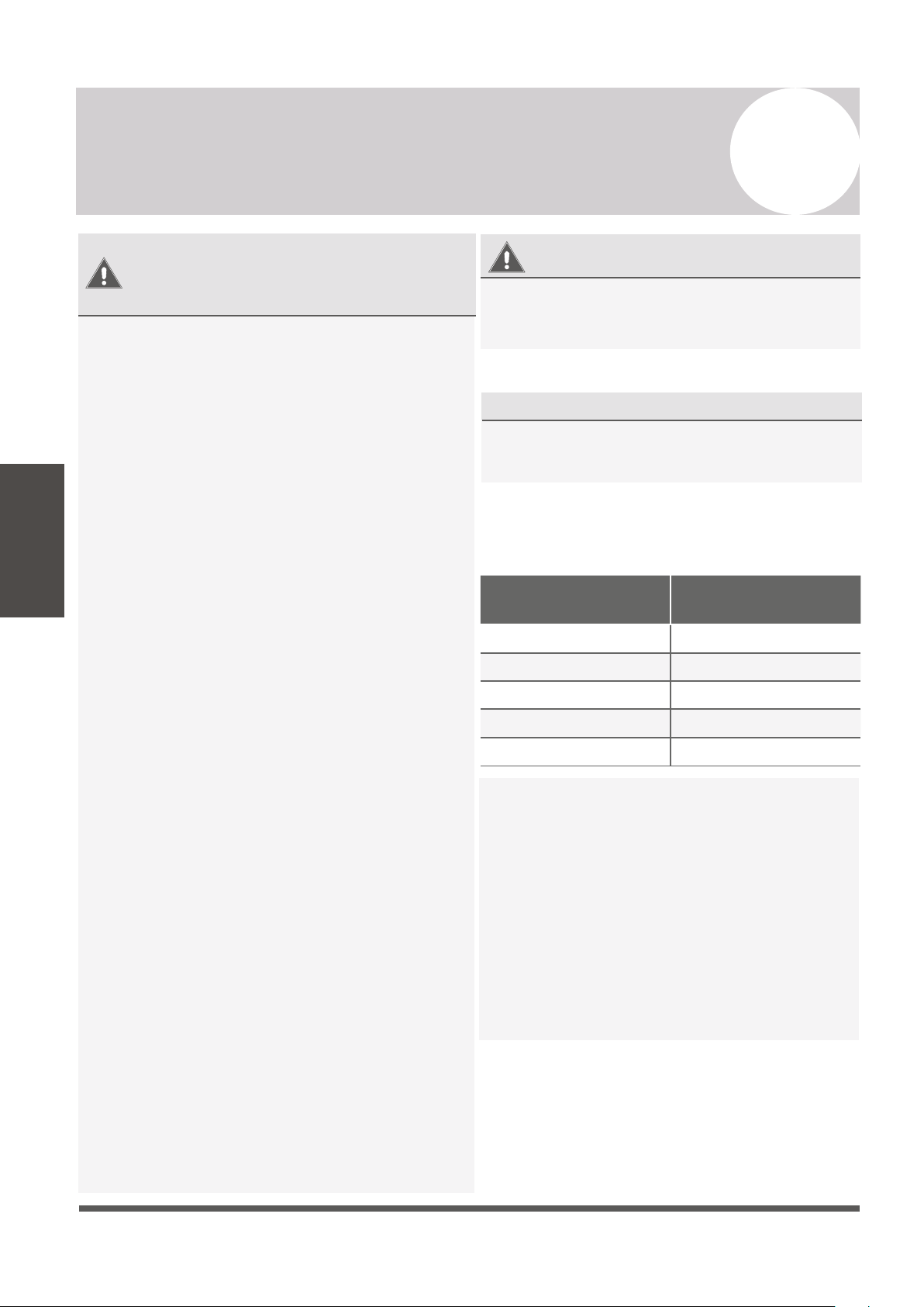
North America
Appliance Amps (A)
AWG
10 18
13 16
15 14
20 12
30 10
Using wire strippers, strip the rubber jacket from
both ends of cable to reveal about 40mm (1.5 in)
of the wires inside. Strip the insulation from the
ends of the wires. Using a wire crimper, crimp
u-lugs on the ends of the wires. Note that some
cables come with preinstalled u-lugs from factory.
INDOOR UNIT TERMINAL POSITION #1 connects
to OUTDOOR UNIT TERMINAL POSITION #1.
INDOOR UNIT TERMINAL POSITION #2 connects
to OUTDOOR UNIT TERMINAL POSITION #2.
INDOOR UNIT TERMINAL POSITION #3 connects
to OUTDOOR UNIT TERMINAL POSITION #3.
INDOOR UNIT TERMINAL POSITION “GROUND”
connects to OUTDOOR UNIT GROUNDING LUG
Loading ...
Loading ...
Loading ...