
14
INTRODUCTION
Thank you for choosing a De’Longhi product. Please take a few
moments to read the instructions to avoid risks or damage to the
appliance.
Download the App!
This appliance can be used also with the APP named “Delonghi
Comfort” that can be downloaded from the App Store® or from
Google Play.
To gain access to all functions you need a local net (Home WLAN)
with access to Internet. Further check there are no obstacles to
the Internet access, such as Firewall, Proxy, authentications, etc.
Through the App you can easily control Pinguino from home or
outside.
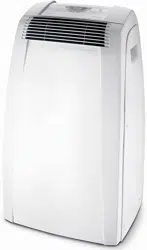
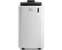
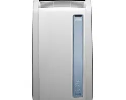
DESCRIPTION
Description of the appliance (see page 3 - A)
A1 air outlet ap
A2 control panel
A3 handles
A4 castors
A5 BioSilver lter
A6 air intake grille
A7 air exhaust hose housing
A8 air intake grille
A9 power cable
A10 drainage hose with cap
A11 remote control signal receiver
A12 remote control compartment
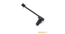
Description of the accessories (see page 3 - B)
B1 wall ange with cap
B2 air exhaust hose
B3 hose adaptor
B4 adapter for window bracket
B5 window bracket with wing nut
B6 adapter for wall mounting/window outlet
B7 window outlet
B8 remote control
B9 window bracket cap
ELECTRICAL CONNECTION
Before plugging into the mains, check the following:
• the mains voltage is the same as that indicated on the plate
on the back of the appliance;
• the socket and electrical line are sized to support the load
required;
• the socket is the proper type for the plug, otherwise, re-
place the socket;
• the socket is connected to an ecient earthing system.
The manufacturer is not responsible in the event of non-
compliance with these injury prevention standards.
The power cable must only be replaced by specialised
technicians.
USE
The instructions below will enable you to prepare your air con-
ditioner for operation as eciently as possible. Before use, make
sure the air intake and outlet grilles are unobstructed.
Please note: This appliance is provided with an auto-evapora-
tion feature for condensate removal during cooling and dehu-
midifying modes.
AIR CONDITIONING WITHOUT INSTALLATION
CASEMENT WINDOW
If you have a casement window proceed as follows:
• Fit the air exhaust hose (B2) in the relevant housing located
on the rear side of the appliance (g. 1).
• Screw the window outlet (B7) and place outside the win-
dow to exhaust the hot air (g. 2).
DOUBLEHUNG WINDOW
If you have a double-hung window proceed as follows:
• Insert and lock the adapter for window bracket (B4) into
the slot of the window bracket (B5) (g.3)
• Place the window bracket in the window sill, and extend
the bracket fully within the window frame (g. 4).
• Fix the bracket by the wing nut (g. 5) (Should the window
bracket be too large for the window the plastic can be cut
with a saw by a qualied professional).
• Insert the air exhaust hose (B2) into the adapter for win-
dow bracket (B4) and rotate it as shown in g. 6.
• In order to facilitate the tting of the air exhaust hose (B2)
in the relevant housing located on the rear side of the ap-
pliance, position the hose adapter ‘s tabs (B3) in a vertical
axis as shown in g. 7 and proceed as shown in g.1.
15
SLIDING WINDOWS
• Thanks to the locking wing nut, it’s possible to use the win-
dow bracket also for sliding windows. Position the bracket
vetically with the hole in the lower part so to allow a easier
installation of the exhaust hose.
AIR CONDITIONING WITH INSTALLATION
• Fit the air exhaust hose (B2) in the relevant housing located
on the rear side of the appliance (g. 1).
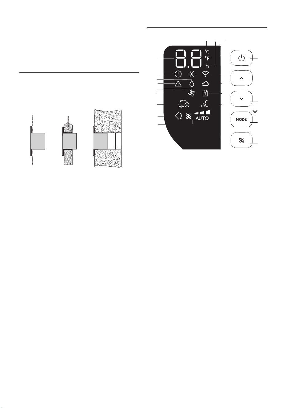
• Drill a hole 150 mm in an outside wall or through a window
panel. Respect the distances, dimensions and heigh of the
hole given in gure 8.
ø 150mm
in the
window
panel
in the wooden
kickboard of a
French window
in the wall: you are
recommended to
insulate the section
of wall using suita-
ble insulation.
• Fit the wall ange (B1) into the hole.
• Fit the air exahaust hose (B2) into the wall ange (B1) (Fig.
9)
• When the hose (B2) is not connected, the drilled hole can
be closed with the ange cap (B1).
Please note: As special tools are required for installation, we
suggest you have the appliance installed by specialized person-
nel.
• When installing the air conditioner, you should leave a door
slightly open little as 1 cm to guarantee correct ventilation
and room pressure.
• Keep the air hose as short and free of curves as possible to
avoid constrictions.
OPERATING FROM THE CONTROL PANEL
C1
C20
C18
C12
C11
C10
C9
C13
C6
C15
C16C17
C3
C4
C2
C5
C14
C8
C7
C19
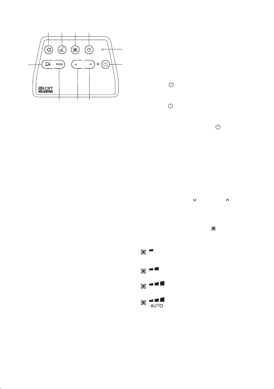
DESCRIPTION OF THE CONTROL PANEL (C)
C1 ON/STAND-BY (on/o) key
C2 Function selection key MODE (air conditioning, dehumidi-
fying, fan, ON-OFF Wi-Fi - reset WLAN settings)
C3 Temperature increase key
C4 Temperature decrease key
C5 Fan speed selection key (MIN/MED/MAX/AUTO)
C6 Air conditioner symbol
C7 Dehumidifyìng symbol
C8 Fan symbol
C9 myEcoReal Feel status indicator
C10 Swing symbol
C11 Fan speed indicator
C12 SILENT symbol
C13 Alarm symbol
C14 Set temperature values, programmed on/o time
C15 Timer symbol
C16 Timer indicator
C17 Set temperature values, programmed on/o time
C18 App Indicator
C19 App timer/calendar
C20 Wi-Fi symbol
16
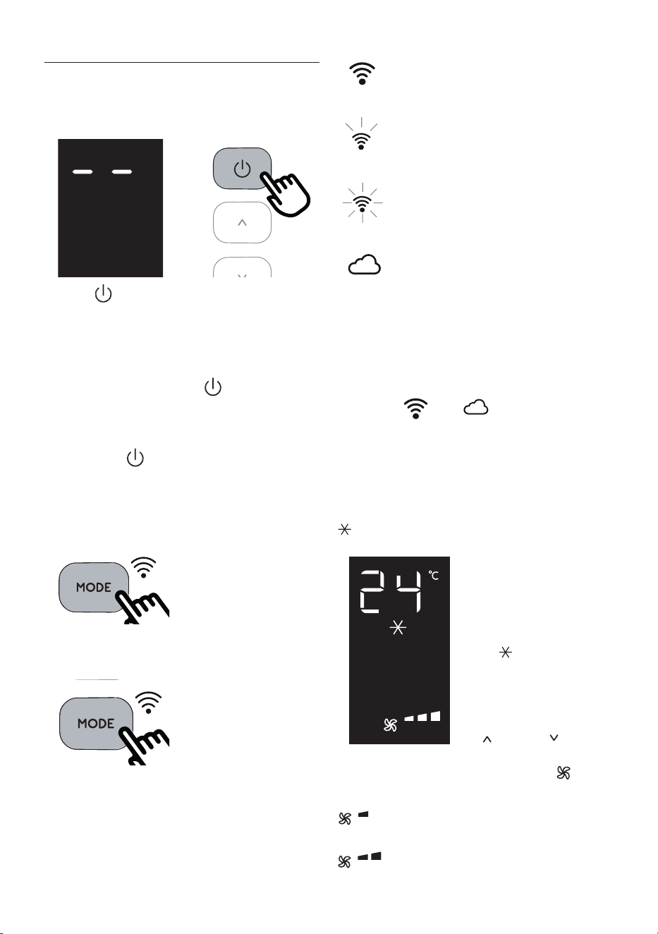
CONTROL PANEL OPERATION
TURNING THE APPLIANCE ON AND OFF
Insert the plug in the socket. Two dashes appear on the display
indicating that the appliance is in stand-by.
Touch the (C1) key to turn on the appliance.
The ap A1 will open after few seconds. When the appliance
comes on the last function set before it was shut o is activated.
Please note: If start-up is not continued, after a few minutes
the display light dims in order to reduce energy consumption.
To turn the appliance o, touch the , key and then pull the
plug.
Please note: Never turn o the air conditioner by simply pulling
the plug. Touch the key in order to put your air conditioner in
stand-by and wait a few minutes before pulling the plug. In this
way, the appliance can perform the operating status checks..
MODES SELECTION
To select the desired operating
mode, touch repeatedly the MODE
key (C2) until the desired function
is selected.
Wi-Fi FUNCTION
To select or deselect the Wi func-
tion, keep touching the MODE key
for 3 seconds.
Once the Wi-Fi icon is displayed it means that the following Wi-Fi
features are available:
SYMBOL WI-FI FIXED
it means that the Wi-Fi features are active AND the
“Home WLAN” has been found.
SLOW FLASHING
it means that the appliance is searching for the
“Home WLAN” .*
FAST FLASHING
it means that the “Home WLAN” has not been
found or has not been set yet.
“APP CONTROL “ ICON
When the APP CONTROL icon appears it means that
the last command has been received via app.
If the memorized “Home WLAN” settings needs to be changed,
proceed as follows:
a) keep touching for about 20 seconds the MODE button C2 on
the control panel until a prolonged beep is emitted;
b) the icon and blink simoultaneously.
c) use the app to enter the new WLAN settings into the unit.
* Note: In standby, the search for “Home WLAN” stops after ap-
proximately 1 hour. It will resume once the appliance is turned
on again.
AIR CONDITIONING MODE
This is ideal for hot and humid
weather when the room needs to
be both cooled and dehumidied.
To correctly set this mode:
• Touch repeatedly the MODE
key (C2) until the air condition-
ing symbol appears. The
display will show the desired
temperature.
• To change the temperature
to be reached, touch the
(C3) or (C4) key.
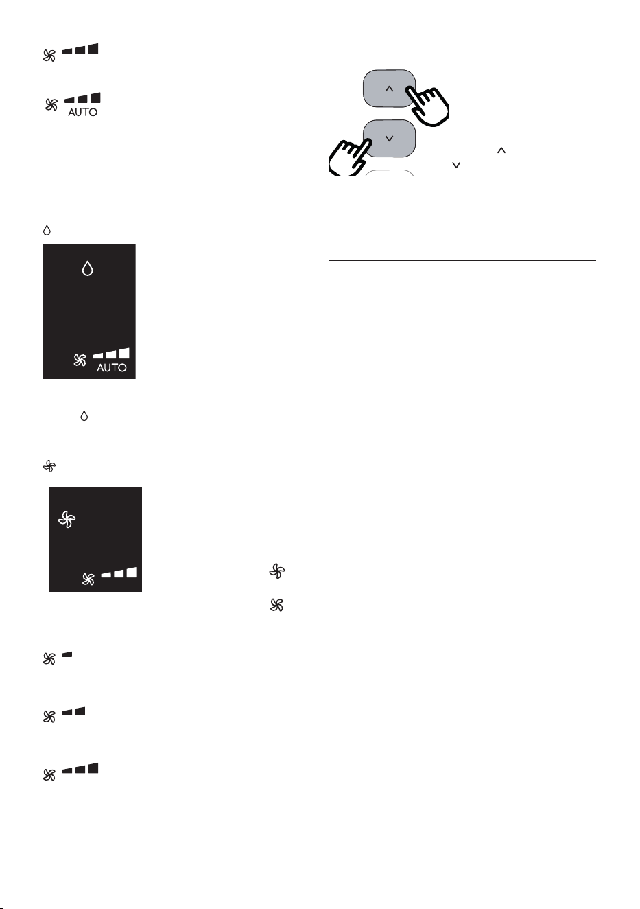
• Select the desired fan speed by touching the (C5) key.
The speeds available are:
Minimum speed: when maximum silent opera
tion is desired.
Medium speed: when the noise level needs to
be low but with a good comfort level.
17
Maximum speed: to reach the desired
temperature as soon as possible.
The appliance automatically chooses the best
fan speed based on the temperature selected
and the environmental conditions.
The most suitable temperatures during the summer range from 24
to 27°C. However, setting the temperature signicantly lower than
the outdoor temperature is not recommended.
DEHUMIDIFYING MODE
This is ideal for reducing humidity in
the room (spring and autumn, damp
rooms, rainy periods, etc). For this
type of use, the appliance must be set
up as for air conditioning mode. That
is, the air exhaust hose (B2) must be
tted to the appliance to allow the
humidity to be discharged outside.
To correctly set this mode:
• Touch repeatedly the MODE key (C2) until the dehumidify-
ing symbol appears.
• The appliance will automatically choose the best air ow.
FAN MODE
When using this mode, the air ex-
haust hose (B2) does not need to be
attached to the appliance.
To correctly set this mode:
• Touch repeatedly the MODE
(C2) key until the fan sym-
bol appears.
• Select the desired fan speed by touching the key .
The air ows available are:
Minimum air ow: when most silent operation is
desired.
Medium air ow: when the noise level needs to
be low but with a good comfort level.
Maximum air ow: for maximum performance.
SELECT THE TEMPERATURE SCALE
The temperature can be displayed
in °C or °F. To change the tem-
perature unit of measure touch
simultaneously for ten seconds the
increase (C3) and decrease
(C4) key.
OPERATING FROM THE CST (Cool Surround Tec-
nology) REMOTE CONTROL
The CST remote controller is based on Bluetooth® Low Energy
communication with the Pinguino.
The appliance works at its best only when it works together with
the CST remote control.
INSERTING OR REPLACING THE BATTERIES
• Remove the cover on the rear of the remote control.
• Insert or replace the batteries with two new LR6 “AA” 1.5V
batteries, inserting them correctly (see the instructions in-
side the battery compartment) (g. 10).
• Replace the cover.
If the remote control unit is replaced or discarded, the bat-
teries must be removed and disposed of in accordance with
current legislation as they are harmful to the environment.
Do not mix old and new batteries.
Do not mix alkaline, standard (carbon-zinc) or rechargeable
batteries. Do not dispose of batteries in re. Batteries may
explode or leak. If the remote control is not be used for a
certain length of time, remove the batteries. Use only bat-
tery within the expired date.
Note: when the device is in standby and CST is absent (without
batteries or out of range), the search for the Bluetooth connec-
tion with CST will stop after about 1 hour. For it to resume, it is
necessary to turn the apppliance back on.
18
DESCRIPTION OF THE CST REMOTE CONTROL
D1
D10
D5
D3D2D9
D8
D4D6 D7
D1 ON/STAND-BY (on/o) button
D2 SILENT button
D3 Air ow button
D4 Decrease button
D5 Countdown Timer
D6 MODE button
D7 Increase button
D8 myEcoReal Feel button
D9 Swing button (ap swing)
D10 Indication LED
USING THE CST REMOTE CONTROL
The CST remote control is an innovative technology that allows
a better wellbeings regulation, thanks to the sensors provided.
In order to optimize the wellbeings conditions around you, we
suggest you to keep it near you.
• The remote control must be no more than about 10 meters
away from the appliance (g. 10) (even in non line of sight).
The maximum range may be lower depending on the envi-
ronment. It belongs to Bluetooth class 2 device class.
• The CST remote control must be handled with care. Do not
drop it or expose it to direct sunlight or sources of heat. It
is advisable to keep the CST remote Control Unit lied over a
table or a plan surface.
Do not hold the CST remote Control in your hand for long
time to avoid altering the reading of the sensors.
The CST sensors are also disabled if the CST remote control
is positioned at a distance less than 1 m from the unit.
• The CST remote control is equipped with touch sensitive
buttons.
•
The CST remote control is equipped with a double color built-
in LED (D10) (white/red). White indications are used for:
- signaling the touching of each button with 3 fast
ashes
- every 30 seconds it blinks for data transmission
- signaling the entering of pairing phase with periodic
blinking
- signaling the batteries good status
• The same indications but in red color mean that the batter-
ies begin to be exhausted.
Please note: The remote control can be safely stored in the ap-
propriate compartment (A11).
TURNING THE APPLIANCE ON/OFF
• Plug into the outlet.
• Touch the
C1C2
C4
C11
C13
C12
C9
C7
C5
C6
C3
C16
C14
C10
C15
C17
C8
ON/STAND-BY button (D1). When turned on,
the air conditioner starts operating in the same mode as
when it was turned o.
• Touch the
C1C2
C4
C11
C13
C12
C9
C7
C5
C6
C3
C16
C14
C10
C15
C17
C8
ON/STAND-BY button (D1) again to switch the
appliance o.
Please note: Never switch the appliance o by removing the
plug. Always switch it o by touching the
C1C2
C4
C11
C13
C12
C9
C7
C5
C6
C3
C16
C14
C10
C15
C17
C8
ON/STAND-BY but-
ton (D1) and waiting few minutes before removing the plug.
Only in this way the appliance will perform the standard check-
ings.
SELECTING THE OPERATING MODES
The operating modes available on the CST remote control
through the MODE button (D6) correspond to those on the ap-
pliance control panel (C).
SELECTING THE TEMPERATURES
In conditioning mode touch button (D4) or (D7) to select
the desired temperature.
SELECTING THE AIR FLOW
In conditioning and fan modes, touch button (D3) to select
the desired air ow.
The air ows available are:
Minimum air ow: when most silent operation is
desired.
Medium air ow: when the noise level needs to
be low but with a good comfort level.
Maximum air ow: for maximum performance.
Auto air ow: the appliance automatically
chooses the air ow based on the temperature
selected and the environmental conditions. This
selection is only available in conditioning mode.
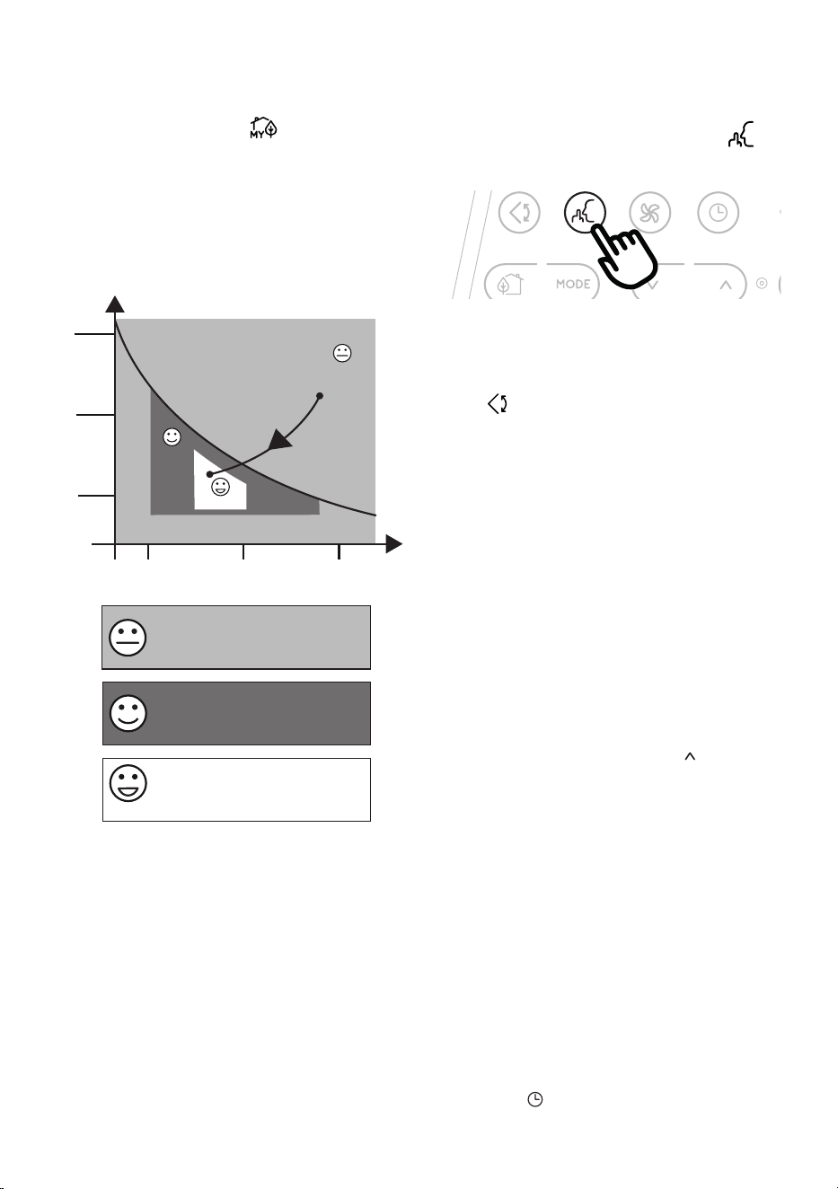
myEcoReal Feel FUNCTION
myEcoReal Feel is the innovative De’Longhi technology that
works simultaneously on temperature reduction and humidity
control, securing best comfort level. With traditional systems,
during working time, optimal comfort conditions may be
19
reached but not secured over time. myEcoReal Feel, once opti-
mal comfort is reached, PAC automatically modulates compres-
sor action and air ow, to keep it over time.
To activate the function, touch the button (D8) on remote
control and the myEcoReal Feel symbol appears.
After approx. 1 minute, the myEcoReal Feel indicator (C9) turns
on. It changes color when approaching the best comfort level
(see following diagram).
Please note: For this type of use, the appliance must be set up as
for air conditioning mode.
Perfect!
Perfect!
Perfect!
HUMIDITY
TEMPERATURE
HIGH
MEDIUM
LOW
HIGH
MEDIUM
LOW
Operating curve
Perfect!
Perfect!
ORANGE LIGHT: Room conditions far
from optimal level.
GREEN LIGHT: Most people feel good
room conditions, near optimal level.
BLUE LIGHT: Best comfort level.
• The well-being feeling is a subjective condition: for this
reason, dierent people may judge dierently the same
environmental conditions.
• In particularly severe environmental conditions (large size
of the environment, high temperature or humidity outside,
poor insulation of the room, too many of people or strong
heat load in the room, strong exposure to the sun ...) this
device may not be able to reach the best comfort level.
SILENT FUNCTION
(available in conditioning mode
only)
By activating this function, the operating noise is further re-
duced. To activate it, touch on the remote control the but-
ton (D2). The display shows the relative symbol (C12).
SWING FUNCTION
This function moves the ap evenly distributing the air into the
room.
When the Swing button (D9) is touched, the ap will begin
to move forwards and backwards alternatively.
If touched again, the ap will be locked into its current position.
When the button is next touched, the ap will start to move for-
wards and backwards again.
Please note: in order to avoid damaging the internal mecha-
nisms, the ap must not be moved manually.
REPEAT PAIRING OF CST REMOTE CONTROL
The CST remote control is already paired to the bundled Pinguino
appliance. In case the user wants to perform a pairing with an-
other Pinguino device, or in case of a pairing of brand new CST
remote control, the user needs to put the unit in Stand-by mode
and keep touched for 10 sec sthe MODE selection button (D6) on
the CST remote control. The Led (D10) starts blinking periodi-
cally indicating the pairing phase.
The user is then asked to press for 10 sec the button (C3) on
the Pinguino unit until a double beep is emitted. The pairing
phase is signaled on display by means of a fast ashing of the
dot in the middle of the digits.
When the two devices complete the pairing dialogue, the PAC
emits a double ‘beep’, the display will show the normal visualiza-
tion for Standby. The pairing must be done within 60 sec.
SETTING THE TIMER
The timer allows the delayed start up or shut down of the appli-
ance. This function will prevent wasting electricity by optimising
the operating periods.
How to program delayed shut down
• While the appliance is on in any operating mode, delayed
shut down can be programmed.
• Touch the
C1C2
C4
C11
C13
C12
C9
C7
C5
C6
C3
C16
C14
C10
C15
C17
C8
timer button (D5): the timer symbol
(C15) and hours (C16) light up.
20
• Touch the (D4) and (D7) buttons until the desired
numbers of hours to shut down appears on the display.
A few seconds after the timer is set, the setting is acquired, the
display shows the operating mode and the timer symbol stays lit.
Once the set time is elapsed, the air conditioner goes into standby.
To cancel the timer program, touch the
C1C2
C4
C11
C13
C12
C9
C7
C5
C6
C3
C16
C14
C10
C15
C17
C8
timer button (D5)
twice. The timer symbol (C15) will go o.
Please note: Once the timer has been activated, by touching the
timer button only one time, the remaining hours to shut down
will be displayed.
How to program delayed start up
• Plug in the appliance and set to standby.
• Touch the
C1C2
C4
C11
C13
C12
C9
C7
C5
C6
C3
C16
C14
C10
C15
C17
C8
timer button (D5): the timer symbol (C15)
and hours (C16) light up.
• Touch the (D4) and (D7) buttons until the desired
numbers of hours to start up appears. Start up can be pro-
grammed at any time within the 24 hours that follow.
When the set time is elapsed, the appliance will start to operate
in the same operating mode that was previously set.
To cancel the timer program, touch the timer button (D5) twice.
The timer symbol (C15) will go o.
Please note: Once the timer has been activated, by touching the
timer key only one time, the remaining hours to the start up will
be displayed.
Note: Timer programming is also a function of the app: thanks
to the many possibilities of timer programming, you can prevent
wasting electricity by optimizing the operating period with
weekly scheduling, setting delayed start up or shut down of the
appliance.
USAGE TIPS
• The CST remote control has humidity/temperature sensors
onboard. It is suggested not to completely cover it with
hands or clothes; it is as well suggested not to place in ob-
structed air ow zones. In addition to that it is preferable
to keep the device far for direct sunlight exposure or heat
sources in order to avoid miss sensor readings.
• The CST remote control is equipped with touch sensitive
buttons. It is suggested to use it with clean hands and
without dust or liquids/humidity over it.
• The CST remote control is expected to run for about 6
months with the same battery pack. This assumption is
based on the use of 2300 mAh LR6 “AA” batteries.
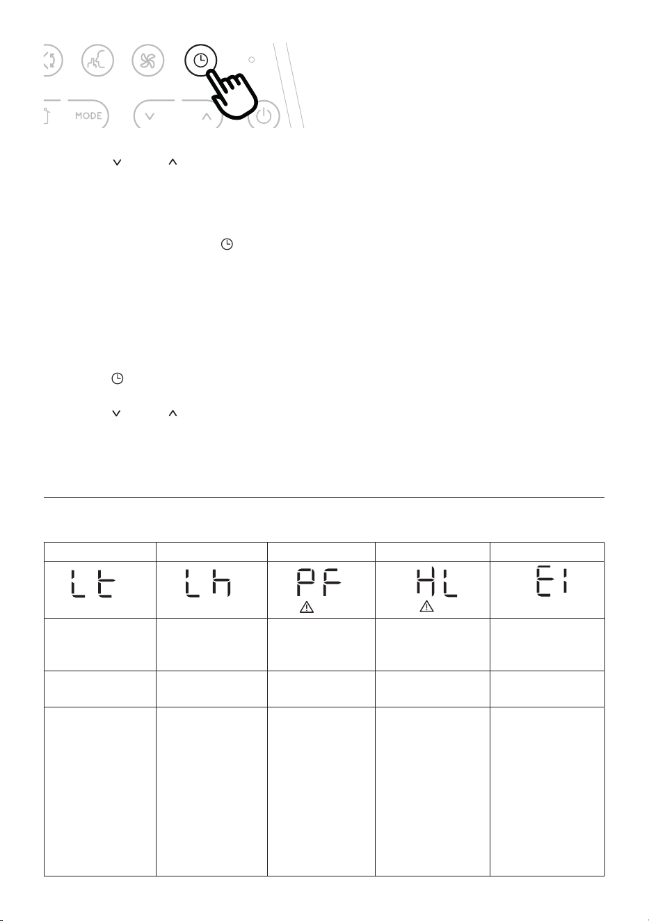
SELFDIAGNOSIS
The appliance has a self diagnosis system to identify a number of warning/malfunctions.
Error messages are displayed on the appliance display.
IF ... IS DISPLAYED, IF ... IS DISPLAYED, IF ... IS DISPLAYED, IF ... IS DISPLAYED, IF ... IS DISPLAYED,
“Low Temperature”
(Frost prevention)
Low humidity “Probe Failure”
(Probe damaged)
“High Level”
(Internal tray full)
“Communication Failure”
(Internal communication
issue)
..WHAT SHOULD I DO? ..WHAT SHOULD I DO? ..WHAT SHOULD
I DO?
..WHAT SHOULD I DO? ..WHAT SHOULD I DO?
The appliance is tted
with a frost protection
device to avoid excessive
formation of ice. The
appliance starts up again
automatically when the
defrosting process is
completed.
This message will only
be displayed when my-
EcoReal Feel function,
indicating that the room
humidity level is extre-
mely low. To resume
operation, switch the
unit to any other mode
other than the myEco-
Real Feel function.
If this is displayed, con-
tact your local authori-
zed service center
Empty the internal safety
tank following the in-
structions in the section
“End of season opera-
tions”
If this is displayed, con-
tact your local authorized
service center.
21
TIPS FOR CORRECT USE
To ensure optimal results from your air conditioner, follow these
recommendations:
• close the windows and doors in the room to be air condi-
tioned. When installing the air conditioner semi-perma-
nently, you should leave a door slightly open (as little as 1
cm) to guarantee proper ventilation.
• Never use the appliance in very damp rooms (laundries for
example).
• Protect the room from direct exposure to the sun by par-
tially closing curtains and/or blinds to make the appliance
much more economical to run.
• Never use the appliance outdoors.
•
Make sure there are no heat sources in the room.
• Make sure the air conditioner is standing on a level surface.
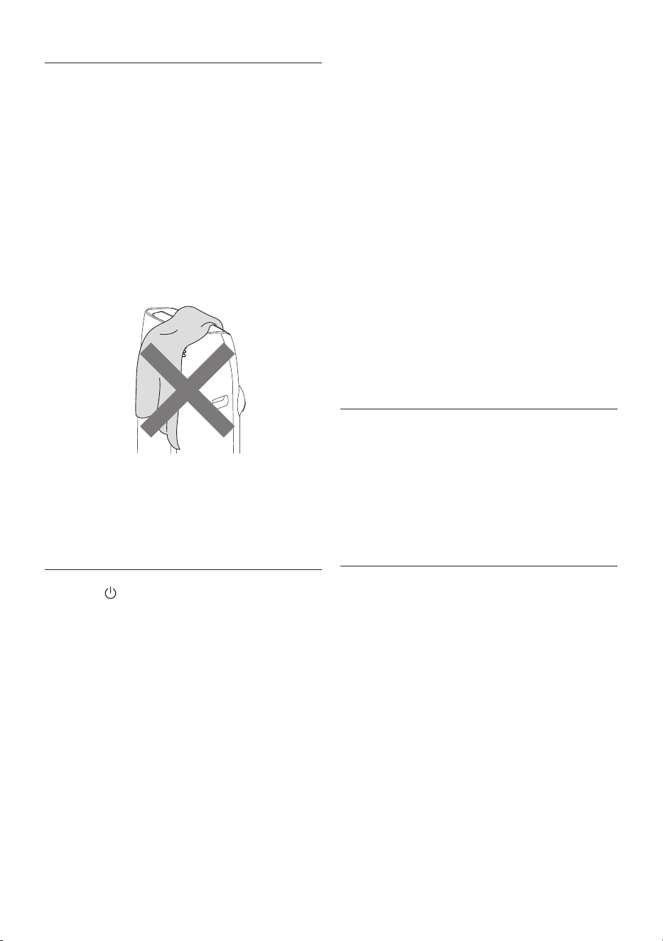
do not cover the appliance
• Never rest objects of any kind on the air conditioner.
• Never obstruct the air intake or outlet ap.
CLEANING
Before cleaning or maintenance, turn the appliance o by
touching the
C1C2
C4
C11
C13
C12
C9
C7
C5
C6
C3
C16
C14
C10
C15
C17
C8
button, then unplug from the outlet.
CLEANING THE CABINET
You should clean the appliance with a slightly damp cloth then
dry with a dry cloth. For safety reasons, never wash the air con-
ditioner with water.
Attention! Never use petrol, alcohol or solvents to clean the ap-
pliance. Never spray insecticide liquids or similar.
CLEANING THE BIO SILVER AIR FILTER
The BioSilver lter helps capture dust and pollen and helps re-
duce the growth of bacteria and mold on the lter.
If the lter is dirty, air circulation is compromised and the e-
ciency of the appliance decreases. It is therefore good practice
to clean the lter at regular intervals. The frequency depends
on the duration and conditions of operation. If the unit is used
constantly or systematically, you are recommended to clean the
lter once a week.
The lter is housed in the intake grille.
To clean the lter, extract as shown in g. 11.
Use a vacuum cleaner to remove the dust collected on the lter.
If it is very dirty, immerse in warm water and rinse a number of
times. The water should never be hotter than 40°C.
After washing the lter, allow it to dry completely before
repositioning it.
START OF SEASON CHECKS
Make sure the power cable and plug are undamaged and the
earth system is ecient.
Follow the installation instructions precisely.
END OF SEASON OPERATIONS
To drain all water from the circuit, remove the external cap by
unscrewing it in the anticlockwise (g. 12) direction and allow
the water to drain out into a basin.
When the appliance is empty, replace the caps.
Clean the lter and dry thoroughly before putting back.
TECHNICAL SPECIFICATIONS
Power supply voltage see rating label
Max. absorbed power
during air conditioning “
Refrigerant “
Cooling capacity “
Frequency 2402.0-2483.5 MHz
Maximum transmission power 0,0631 W
LIMIT CONDITIONS
Room temperature for air conditioning 18° ÷ 35°C
Transport, lling, cleaning, recovery and disposal of
refrigerant should be performed by a technical service
centre appointed by the manufacturer only.
The appliance should be disposed of by a specialist centre
appointed by the manufacturer only.
Attention! TO AVOID DAMAGE TO THE UNIT:
NEVER TRANSPORT OR TURN THE APPLIANCE UPSIDE DOWN OR
ON ITS SIDE. IF THIS OCCURS, WAIT 6 HOURS BEFORE TURNING
THE APPLIANCE ON, 24 HOURS IS RECOMMENDED. After the unit
has been on its side, oil needs to return to the compressor to en-
sure proper function. Without allowing the unit this time (6-24
hours) the unit may function for only a short time, and then the
compressor will break down from lack of oil.

22
TROUBLESHOOTING
PROBLEM CAUSE SOLUTION
The air conditioner does not come on it is not plugged into the outlet plug into the outlet
there is no current wait
the internal safety device has tripped call the Service Center
The air conditioner works for a short
time only
there are bends or kinks in the air
exhaust hose
position the air hose correctly, keeping it
as short and free of curves as possible to
avoid bottlenecks
something is preventing the air from
being discharged
check and remove any obstacles
obstructing air discharge
The air conditioner works, but does not
cool the room
windows, doors and/or curtains open close doors, windows and curtains,
bearing in mind the “TIPS FOR CORRECT
USE” given above
there are heat sources in the room (oven,
hairdryer, etc
eliminate the heat sources
the air exhaust hose is detached from
the appliance
t the air exhaust hose in the housing at
the back of the appliance (g. 1).
lter clogged clean or replace the lter as described
above
the technical specication of the
appliance is not adequate for the room
in which it is located.
During operation, there is an unpleasant
smell in the room
lter clogged clean the lter as described above
The air conditioner does not operate for
about three minutes after restarting it
an internal safety device prevents the
appliance from being restarted until
three minutes have elapsed since it was
last turned o
wait. This delay is part of normal
operation.
One of the following messages is
displayed: Lt/Lh/PF/HL/E1
the appliance has a self diagnosis system
to identify a number of malfunctions.
see the SELF-DIAGNOSIS chapter