
Loading ...
Loading ...
Loading ...
11
ENGLISH
disables the lasers as well as locking the pendulum, and
should always be placed in the LOCKED/OFF position when
the laser is not inuse.
Checking Laser Accuracy
The laser tools are sealed and calibrated at the factory. It is
recommended that you perform an accuracy check prior
to using the laser for the first time (in case the laser was
exposed to extreme temperatures) and then regularly to
ensure the accuracy of your work. When performing any
of the accuracy checks listed in this manual, follow these
guidelines:
• Use the largest area/distance possible, closest to the
operating distance. The greater the area/distance, the
easier to measure the accuracy of thelaser.
• Place the laser on asmooth, flat, stable surface that is
level in bothdirections.
• Mark the center of the laserbeam.
Field Calibration Check
Checking Accuracy – Horizontal Beam,
Scan Direction (Fig. F)
Checking the horizontal scan calibration of the laser requires
two walls at least 30' (9 m) apart. It is important to conduct
a calibration check using a distance no shorter than the
distance of the applications for which the tool will beused.
1. Attach the laser to a wall using its pivot bracket. Make
sure the laser is facing straightahead.
2. Turn on the laser's horizontal beam and pivot the laser
approximately 45˚ so that the right‑most end of the laser
line is striking the opposing wall at a distance of at least
30' (9 m). Mark the center of the beam (a).
3. Pivot the laser approximately 90˚ to bring the left‑most
end of the laser line around to the mark made in Step 2.
Mark the center of the beam (b).
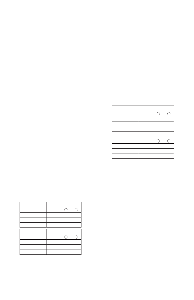
4. Measure the vertical distance between themarks.
• If the measurement is greater than the values shown
below, the laser must be serviced at an authorized
servicecenter.
Distance
Between Walls
Allowable Distance
Between
a
and
b
30' 1/8"
40' 5/32"
50' 7/32"
Distance
Between Walls
Allowable Distance
Between
a
and
b
9.0 m 3.1 mm
12.0 m 4.2 mm
15.0 m 5.2 mm
Checking Accuracy – Horizontal Beam,
Pitch Direction (Fig. G)
Checking the horizontal pitch calibration of the laser requires
a single wall at least 30' (9 m) long. It is important to conduct
a calibration check using a distance no shorter than the
distance of the applications for which the tool will beused.
1. Attach the laser to one end of a wall using its
pivotbracket.
2. Turn on the laser's horizontal beam and pivot the laser
toward the opposite end of the wall and approximately
parallel to the adjacentwall.
3. Mark the center of the beam at two locations (a, b) at
least 30' (9m)apart.
4. Reposition the laser to the opposite end of thewall.
5. Turn on the laser's horizontal beam and pivot the laser
back toward the first end of the wall and approximately
parallel to the adjacentwall.
6. Adjust the height of the laser so that the center of the
beam is aligned with the nearest mark (b).
7. Mark the center of the beam (c) directly above or below
the farthest mark (a).
8. Measure the distance between these two marks(a,c).
• If the measurement is greater than the values shown
below, the laser must be serviced at an authorized
servicecenter.
Distance
Between Walls
Allowable Distance
Between
a
and
c
30' 1/4"
40' 5/16"
50' 13/32"
Distance
Between Walls
Allowable Distance
Between
a
and
c
9.0 m 6.2 mm
12.0 m 8.3 mm
15.0 m 10.4 mm
Checking Accuracy – Vertical Beam (Fig. H)
Checking the vertical (plumb) calibration of the laser can be
most accurately done when there is a substantial amount of
vertical height available, ideally 20' (6m), with one person
on the floor positioning the laser and another person near
a ceiling to mark the position of the beam. It is important
to conduct a calibration check using a distance no shorter
than the distance of the applications for which the tool will
beused.
1. Start by marking a 5' (1.5 m) line on thefloor.
2. Turn on the laser's vertical beam and position the unit at
one end of the line, facing theline.
3. Adjust the unit so its beam is aligned and centered on
the line on thefloor.
4. Mark the position of the laser beam on the ceiling (a).
Mark the center of the laser beam directly over the
midpoint of the line on thefloor.
5. Reposition the laser at the other end of the line on the
floor. Adjust the unit once again so its beam is aligned
and centered on the line on thefloor.
6. Mark the position of the laser beam on the ceiling (b),
directly beside the first mark (a).
7. Measure the distance between these twomarks.
Loading ...
Loading ...
Loading ...