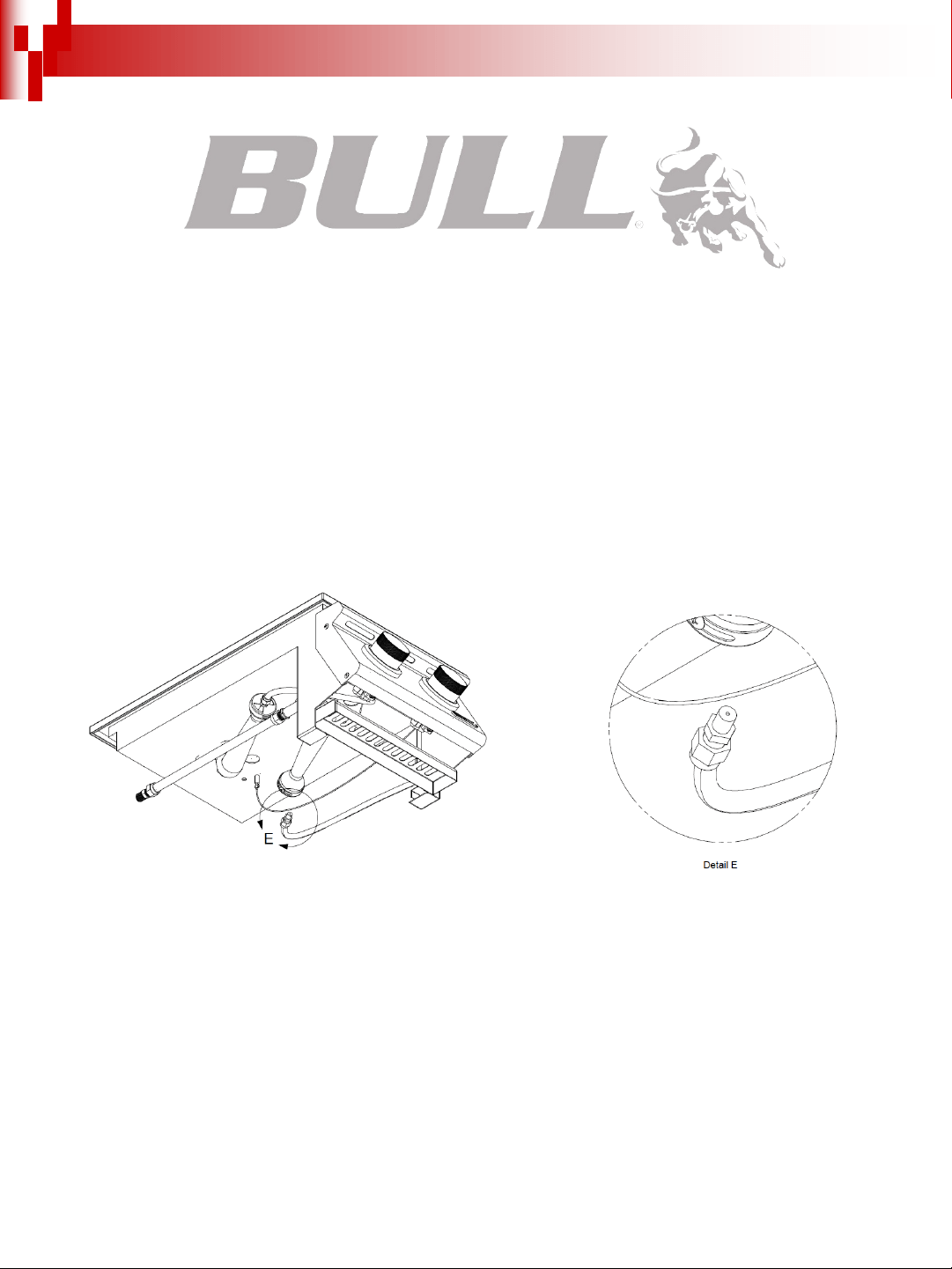
ASSEMBLY & OPERATING INSTRUCTIONS
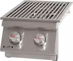
MODEL #30008 SLIDE-IN DOUBLE SIDEBURNER STAINLESS STEEL, BUILT-IN, L.P. (PROPANE)
MODEL #30009 SLIDE-IN DOUBLE SIDEBURNER STAINLESS STEEL, BUILT-IN, N.G. (NATURAL GAS)

TABLE OF CONTENTS PAGE #
SAFETY INSTRUCTIONS
THE LOCATION FOR YOUR SLIDE-IN DOUBLE SIDEBURNER……..…….….……………………….....……….…………………...... 23
CHECKING FOR GAS LEAKS………………………………………………………………………………………...…..……………………....32
NATURAL GAS SAFETY…………………………………….……………………….……..………………….……………….…..…….…….... 3.4
PROPANE GAS SAFETY…………………………………………………………………………………………………….….……………….... 45
INSTALLATION INSTRUCTIONS
SPECIFICATIONS FOR SLIDE-IN DOUBLE SIDEBURNER STRUCTURE..…..…….……………………...………..……………….... 5
CONNECTING TO GAS SOURCE…………………………………………………..………………...…………………………………….........6
NATURAL GAS CONNECTIONS……………………………………………..….………….….….….……….…….……………………….….6
PROPANE GAS CONNECTIONS………………………………………...….……..…..….…….………….…….…...…….…….…….….......6
OUTDOOR NATURAL GAS SLIDE-IN DOUBLE SIDEBURNER INSTALLATION SPECIFICATIONS….….…….……...…….......……7
OUTDOOR PROPANE GAS SLIDE-IN DOUBLE SIDEBURNER INSTALLATION SPECIFICATIONS………………….……...……….89
LP GAS TANK RETENTION...................................................................................................................................................................99
INSPECTING / CLEANING BURNERS AND GAS VALVES
BURNER CLEANING..............................................................................................................................................................................100
BURNER REPLACEMENT INTO INSERT……………….…….….…….…….…….…….….…………..…...…..…...…..….....…........…...111
IGNITER CHECK……………………………………………………………………………………….....….……..….………….………...……111
BURNER OPERATION CHECK………………………….………………….….….….….….….….….…..…..…..…….…….....…........……..111
COOKING COMPONENT………………………………………………………………………….….…...……….……….….….……………....122
LIGHTING & OPERATING INSTRUCTIONS…
LIGHTING PROCEDURES……………………………………………………….……………..…...….….…..…......…......….…............…...133
OPERATING PROCEDURE…………………………………………………….…………..….….……………………….…….…..…...….…..133
CLEANING & MAINTENANCE…………………………………………………………………………………………..……………..………………144
TROUBLESHOOTING
IF SLIDE-IN DOUBLE SIDEBURNER FAILS TO OPERATE PROPERLY………..................................................................................155
FLASH BACK...........................................................................................................................................................................................155
PRODUCT REGISTRATION AND REPLACEMENT PART ORDERING INSTRUCTIONS..............................................................................16
REPLACEMENT
PARTS LIST AND ILLUSTRATION...........................................................................................................................................17
LIMITED WARRANTY POLICY………………………………….………….…….……….……………….…………….………...….…..…..….........18-2020
- READ THE FOLLOWING INSTRUCTIONS CAREFULLY AND BE SURE YOUR SLIDE-IN DOUBLE SIDEBURNER IS PROPERLY
INSTALLED, ASSEMBLED AND CARED FOR. FAILURE TO FOLLOW THESE INSTRUCTIONS MAY RESULT IN SERIOUS BODILY INJURY
AND/OR PROPERTY DAMAGE. IF YOU HAVE QUESTIONS CONCERNING ASSEMBLY OR OPERATION, CONSULT YOUR DEALER, GAS
APPLIANCE SERVICE REPRESENTATIVE OR YOUR GAS COMPANY.
- NOTE TO INSTALLER:
LEAVE THESE INSTRUCTIONS WITH THE CONSUMER AFTER INSTALLATION.
- NOTE TO THE CONSUMER:
RETAIN THESE INSTRUCTIONS FOR FUTURE REFERENCE.
- THIS OUTDOOR COOKING GAS APPLIANCE IS NOT INTENDED TO BE INSTALLED IN OR ON RECREATIONAL VEHICLES AND/OR
BOATS.
*FOR WARRANTY PURPOSES, PLEASE RECORD YOUR MODEL NUMBER, SERIAL NUMBER, DATE OF PURCHASE & A COPY OF YOUR
RECEIPT OR INVOICE IN THE BACK OF YOUR MANUAL ON PAGE 18.
- CE: NOMINAL HEAT INPUT: Qn=7kw. TOTAL HEAT INPUT: Qn=7kw(509.5g/h). LP GAS CATEGORIES: I3+(28-30/37): G30 Butane at 28-
30mbar and G31 Propane at 37mbar. I3B/P(30): G30 Butane and G31 Propane at 30mbar. I3B/P(50): G30 Butane and G31 Propane at
50mbar. NG GAS CATEGORIES: I2H: G20 at 20mbar. I2E: G20 at 20/25mbar. I2E+: G20/25 at 20/25mbar.
v2022.5.171
1

SAFETY INSTRUCTIONS
This gas sideburner must be installed in accordance with local codes or, if in an area without local codes, with the latest edition of the National Fuel
Gas Code ANSI Z223.1. In Canada, installation must conform to the standard CAN/ CGA 1-b149.1 and/or .2 (Installation Code for Gas Burning
Appliances and Equipment) and any local codes. Outside the United States, installation must conform with the latest edition of CE Norms EN498.
Parts that are sealed by the manufacturer or agent must not be altered by the user.
WARNING: Fuels used in gas or oil-fired appliances and the products of combustion of such fuels, contain chemicals known to the State of
California to cause cancer, birth defects and/or reproductive harm. This warning is issued pursuant to California Health & Safety Code Sec.
25249.6.
THE LOCATION FOR YOUR SLIDE-IN DOUBLE SIDEBURNER
DO NOT use your slide-in double sideburner in garages, porches, breezeways, sheds or other enclosed areas. Your double sideburner is to
be used OUTDOORS ONLY, with at least 21 inches/54 cm clearance from the back and side of any combustible surface. The double sideburner
should not be placed under or on top of any surface that will burn. Do not obstruct the flow of combustion and ventilation air around the insert.
PROTECT CHILDREN: Keep children away from the double sideburner during use and until it has cooled after you are finished. Do not allow
children to operate the double sideburner.
CHECKING FOR GAS LEAKS
NEVER TEST FOR GAS LEAKS WHILE THE SLIDE-IN DOUBLE SIDEBURNER IS LIT! Prior to the first use and at the beginning of each new
season (or, if using LP, whenever gas cylinder is changed), it is a must that you check for gas leaks. Follow these steps:
1. Make a soap solution by mixing one part liquid detergent and one part water.
2. Turn off heat control valves, and then turn on gas at source.
3. Apply the soap solution to all gas connections: bubbles will appear in the soap solution if connections are not properly sealed. Tighten or repair
as necessary.
4. If you have a gas leak that you cannot repair, turn off the gas at the source, disconnect fuel line from the double sideburner and immediately call
your dealer and gas supplier for professional assistance.
2
WARNING! FOR YOUR SAFETY...
- DO NOT store or use gasoline or other flammable vapors and liquids in the vicinity of this or
any other appliance.
- DO NOT store empty or full spare gas cylinders and/or chemicals under or near this or any
other appliance.
- Keep the fuel hose away from hot surfaces. Protect the fuel hose from dripping grease. Avoid
unnecessary twisting of the hose. Visually inspect the hose prior to each use for cuts, cracks
excessive wear or other damage and replace if necessary.
- NEVER test for gas leaks with a lighted match or open flame.
- NEVER light double sideburner with lid on or before checking to ensure burner tube is fully
seated over gas valve orifice.
- NEVER lean over cooking surface while lighting the double sideburner. Use barbecue tools
with wood handles and good quality insulated oven mitts when operating double sideburner.
DANGER! IF YOU SMELL GAS...
1. Shutoff gas to the appliance at its source.
2. Extinguish any open flame.
3. Remove double sideburner lid to release any accumulation of fumes.
4. If gas odor persists, immediately contact your gas supplier or your fire department.
READ CAREFULLY BEFORE ASSEMBLY AND OPERATION OF YOUR SLIDE-IN DOUBLE SIDEBURNER
SAFETY INSTRUCTIONS (CONT.)
NATURAL GAS SAFETY
Your natural gas (G20) slide-in double sideburner is designed to operate on natural gas ONLY, at a pressure of 4” water column (W.C.)/10 mbar
regulated at the natural gas regulator that is included with the double sideburner and natural gas orifices located on the ventri tubes. Check with
your gas utility for local gas pressure and with your local municipality for building code requirements. The natural gas orifice size is 1.50mm.
Check with your gas utility or with local building codes for instructions to install gas supply line, or call a licensed and knowledgeable installer.
It is recommended that an “ON-OFF” shutoff valve be installed at the gas supply source:
- Outdoors after gas line piping exits outside wall or before gas line piping enters ground.
- Indoors in the branch fuel line in an accessible location near the supply line.
Pipe sealing compound or pipe thread tape of the type resistant to the action of natural gas must be used on all male pipe thread. Apply
compound or tape to at least the first three threads when making the connection.
Disconnect your double sideburner from the fuel source when the gas supply is being tested at high pressures. This appliance and its individual
shutoff valve must be disconnected from the gas supply piping system during any pressure testing of that system at pressures in excess of 1/2
psig (3.5 kPa)/37 mbar.
Turn off your double sideburner when the gas supply is being tested at low pressures. This appliance must be isolated from the gas supply piping
system by closing its individual valve.
WARNING: The gas valves are preset at the factory to operate on LP or natural gas. If you wish to convert to a different gas type, be sure to
contact your slide-in double sideburner dealer, licensed plumber or authorized service center for further details. Conversion kits are not sold to the
general public and require a professional to perform service. Failure to properly convert a unit can cause serious injury to yourself and/or others,
irreparable damage to your double sideburner and void of warranty.
3
SAFETY! BEWARE OF SPIDERS
CAUTION: BURNERS MUST BE INSPECTED AND CLEANED BEFORE FIRST USE.
Spiders and small insects occasionally spin webs or make nests in the burners during warehousing, transit and/or after long periods of non-use.
These webs can lead to a gas flow obstruction, which could result in a fire in and around the burner tubes. This type of fire is known as “FLASH-
BACK” and can cause serious damage to your double sideburner and create an unsafe operating condition for the user. Although an obstructed
burner tube is not the only cause of “FLASH BACK” it is the most common cause, and frequent inspection and cleaning of the burners is
necessary.
SAFETY INSTRUCTIONS (CONT.)
PROPANE GAS SAFETY
Your propane (G31) slide-in double sideburner is designed to operate on propane gas ONLY, at a pressure of 11” water column (W.C.)/27.4 mbar
when equipped with a propane regulator on the supply line regulated at the residential meter and propane orifices located on the ventri tubes. The
liquid propane orifice size is 0.90mm.
Your propane double sideburner is designed to be used with a standard 20 lb/7 kg gas cylinder. In the United States, the gas cylinder must be
constructed and marked in accordance with specifications of the US Department of Transportation for Propane Gas Cylinders. Outside the United
States, the gas cylinder must be approved under CE NORMS: EN417 and test code 215. Gas cylinder must be constructed and marked with CE
regulations for the European country of destination, where it will be used.
Always keep cylinder securely fastened in an upright position.
Never connect an unregulated propane gas cylinder to the double sideburner.
Do not subject propane cylinders to excessive heat.
CAUTION: Never store a propane gas cylinder inside a building or in the vicinity of any gas-burning appliance.
WARNING: The gas valves are preset at the factory to operate on LP or natural gas. If you wish to convert to a different gas type, be sure to
contact your slide-in double sideburner dealer, licensed plumber or authorized service center for further details. Conversion kits are not sold to the
general public and require a professional to perform service. Failure to properly convert a unit can cause serious injury to yourself and/or others,
irreparable damage to your double sideburner and void of warranty.
4
SAFETY! BEWARE OF SPIDERS
CAUTION: BURNERS MUST BE INSPECTED AND CLEANED BEFORE FIRST USE.
Spiders and small insects occasionally spin webs or make nests in the burners during warehousing, transit and/or after long periods of non-use.
These webs can lead to a gas flow obstruction, which could result in a fire in and around the burner tubes. This type of fire is known as “FLASH-
BACK” and can cause serious damage to your double sideburner and create an unsafe operating condition for the user. Although an obstructed
burner tube is not the only cause of “FLASH BACK” it is the most common cause, and frequent inspection and cleaning of the burners is
necessary.
WARNING
• Do not store a spare or disconnected liquid propane cylinder under or near
this slide-in double sideburner.
• A dented or rusty liquid propane cylinder may be hazardous and should be
check by your liquid propane provider.
• Do not use a liquid propane cylinder with a damaged valve.
READ CAREFULLY BEFORE ASSEMBLY AND OPERATION OF YOUR SLIDE-IN DOUBLE SIDEBURNER
INSTALLATION INSTRUCTIONS
Your Built-in slide-in double sideburner comes to you fully assembled. We strongly recommend professional installation and hookup of the double
sideburner. These instructions will provide you with the measurements necessary for you or your builder to construct a masonry structure to house
your outdoor double sideburner.
NOTE TO INSTALLER: Leave these instructions with the consumer for future reference. The double sideburner must be installed in accordance
with all local building codes. Adapter from 1/2” NPT to BSP 21 mm & regulator are available from Bull dealers and distributors.
SPECIFICATIONS FOR SLIDE-IN DOUBLE SIDEBURNER STRUCTURE
1. Your choice of masonry can be used for cabinet construction for the built-in double sideburner; however it must be non-combustible material.
Keep in mind when choosing a location for your double sideburner that it should NOT be located under any overhead combustible construction.
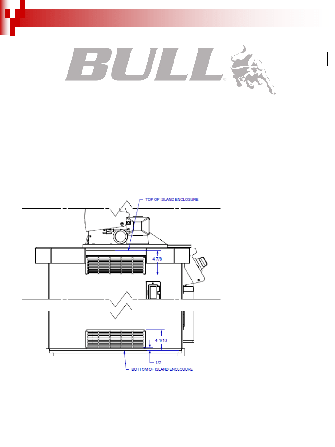
Upper and lower level vents must be provided for combustion air on both sides of built-in cabinet. Vents on BBQ insert must remain unobstructed
to allow for combustion air and ventilation. Upper vents must be located within 5 inches from the top of the island enclosure to the bottom of the
vent. Lower vents must be located within 1 inch from the bottom of the island enclosure to the bottom of the first vent openings and no more than 5
inches from the bottom of the island enclosure to the top of the vent. If not using Bull vents, the vents you use must meet ANSI Standard codes.
The upper vents must have openings that have a total free area of not less than 1 sq in per lb of stored fuel capacity per vent and the lower vents
must have openings that have a total free area of not less than 1/2 sq in per lb of stored fuel capacity per vent. Both upper and lower vent openings
must have minimum dimensions so as to permit the entrance of a 1/8 in diameter rod.
2. The double sideburner requires a wall opening of the following dimensions: See PAGES 7 & 8 for different models.
3. Place double sideburner assembly into wall opening as shown in illustration on pages 7 & 8. The double sideburner rests on side and back
edges of the insert.
4. For propane gas LP TANK STORAGE AREA MUST BE ISOLATED FROM DOUBLE SIDEBURNER AND VENTED.
5. Do not use any combustible materials for this construction. Minimum horizontal clearance to adjacent combustible surface from side and back of
the double sideburner must be 21 inches/54 cm. A 6 inch clearance is required behind double sideburner to allow for ventilation purposes.
5
INSTALLATION INSTRUCTIONS (CONT.)
CONNECTING TO GAS SOURCE
Refer to the following instructions and illustrations for typical gas supply connections. We strongly suggest professional installation and hook-up of
the Gas BBQ. All regulators must meet EN16129 standard.
IMPORTANT: Before connecting grill to gas source, make sure BBQ Grill control knobs are in “OFF” position.
6
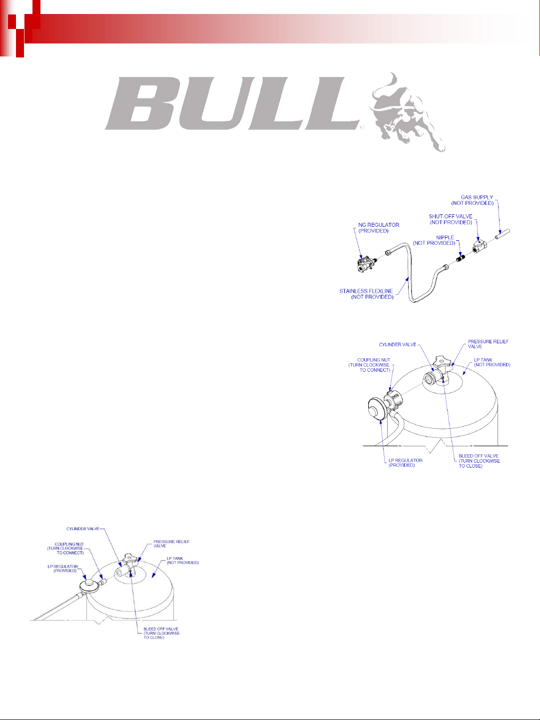
NATURAL GAS CONNECTIONS
IMPORTANT: Bull Outdoor Products does not recommend the use of any quick connect
fittings or lines to the unit. Use of these types of fittings or lines could cause low gas flow
and greatly reduce the performance of the unit.
- Pipe sealing compound or pipe thread tape of the type resistant to the
action of natural gas must be used on all male pipe thread.
- Apply compound or tape to at least the first three threads when making the connection.
- Remove plastic cap from regulator installed on grill.
- Attach stainless steel flex line 3/8”/9.5 mm flare-female end to the regulator.
- Attached the other end of flex line to shut-off valve through a nipple.
- Attach a shut-off valve to gas supply pipe.
PERFORM GAS LEAK CHECK – REFER TO PAGE 2
PROPANE GAS CONNECTIONS
CAUTION: Changing the gas tanks must be done away from any source of ignition.
- In the United States, the LP gas pressure regulator and hose assembly supplied with this
unit must be used without alteration and must be less than 59in/1.5meters in length. If this
assembly needs to be replaced, use only the type 1 specified in the parts list supplied with
this unit. Use a LP tank with a type 1 cylinder valve.
- Outside the United States, the LP gas pressure regulator is not supplied with the grill but
Cavagna Group BS3016 Type 634PR regulator or equivalent can be purchased from Bull
dealers or hardware stores.
- Make sure the tank is firmly secured in an upright position.
- In the United States, turn the black coupling nut of the hose and regulator assembly in a
clockwise direction (see picture to the right).
- Outside the United States, turn the coupling nut of the hose and regulator assembly in a
clockwise direction with an adjustable wrench (see picture below).
- Make sure it is completely threaded onto the cylinder valve before turning gas supply on.
PERFORM GAS LEAK CHECK – REFER TO PAGE 2
INSTALLATION INSTRUCTIONS (CONT.)
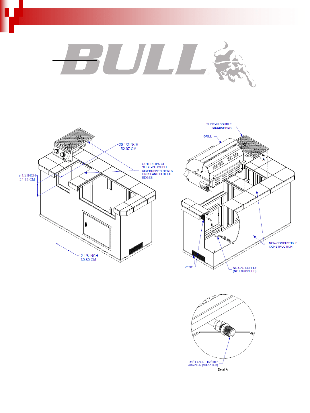
OUTDOOR NATURAL GAS SLIDE-IN DOUBLE SIDEBURNER INSTALLATION SPECIFICATIONS
NOTE:
- Vents must be provided for combustion air and ventilation on both sides of built-in cabinet.
- When choosing a location for your double sideburner keep in mind that it should never be located under any overhead combustible construction.
- The sides and back of the double sideburner should not be any closer than 21 inches/54 cm to combustible construction.
- DO NOT store empty or full spare tanks under or near this or any other appliance.
- There must be a minimum of 6” counter space behind the double sideburner in order to allow for ventilation purposes.
- A 1/2” hard pipe is required connecting to the double sideburner NG regulator.
7
INSTALLATION INSTRUCTIONS (CONT.)
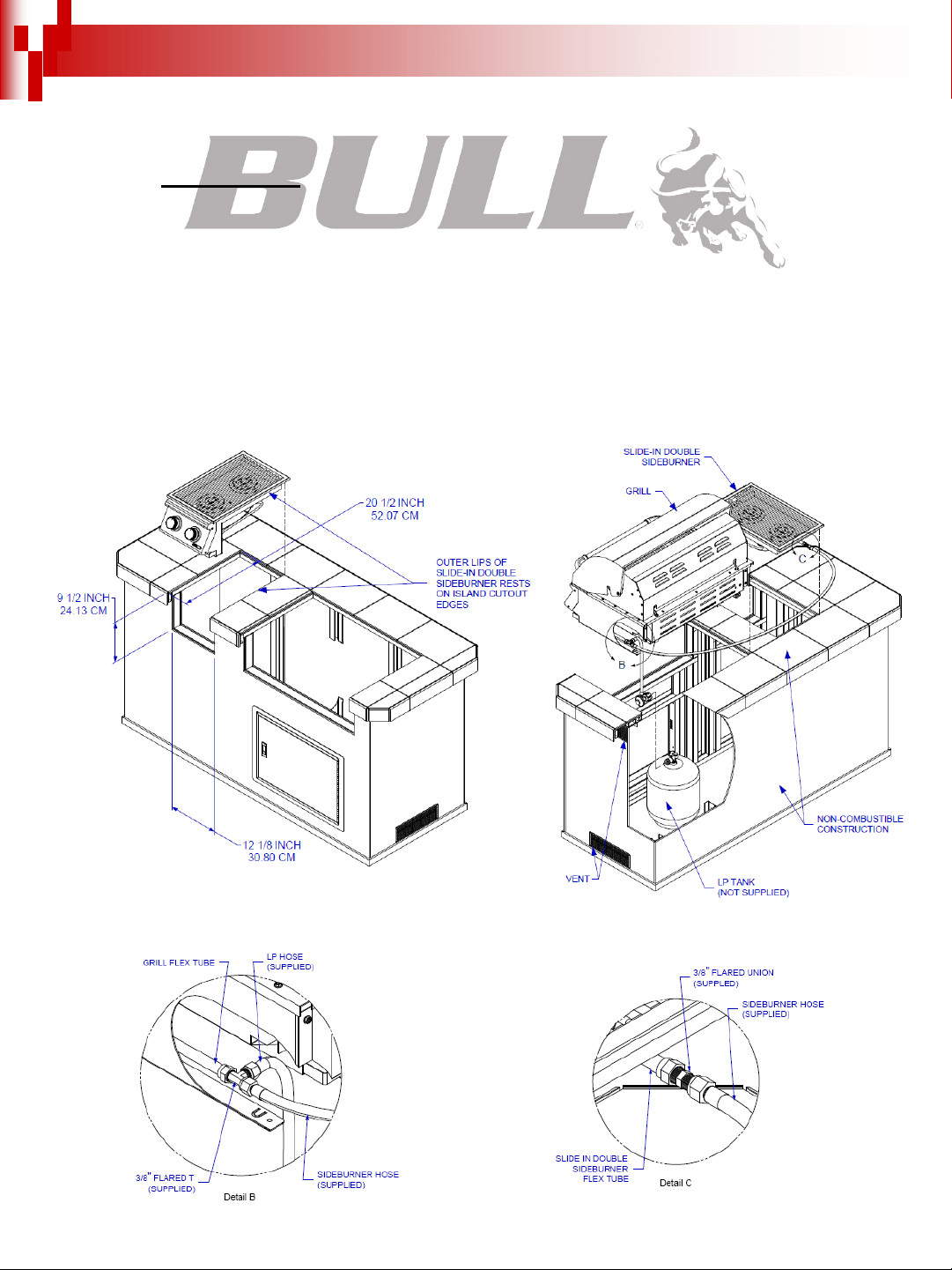
OUTDOOR PROPANE GAS SLIDE-IN DOUBLE SIDEBURNER INSTALLATION
SPECIFICATIONS
NOTE:
- Vents must be provided for combustion air and ventilation on both sides of built-in cabinet.
- When choosing a location for your double sideburner keep in mind that it should never be located under any overhead combustible construction.
- The sides and back of the double sideburner should not be any closer than 21 inches/54 cm to combustible construction.
- DO NOT store empty or full spare tanks under or near this or any other appliance.
- There must be a minimum of 6” counter space behind the double sideburner in order to allow for ventilation purposes.
- The cylinder valve on the tank must be readily accessible for hand operation. The tank must be isolated enough to where it is shielded from
radiation, open flames and protected from foreign matter such as hot drippings.
- There must be access so the tank can be connected, disconnected, inspected and leak tested outside of the cabinet. As well access so that
connections which could be disturbed when installing the tank in the cabinet can be leak tested inside the cabinet.
8
INSTALLATION INSTRUCTIONS (CONT.)
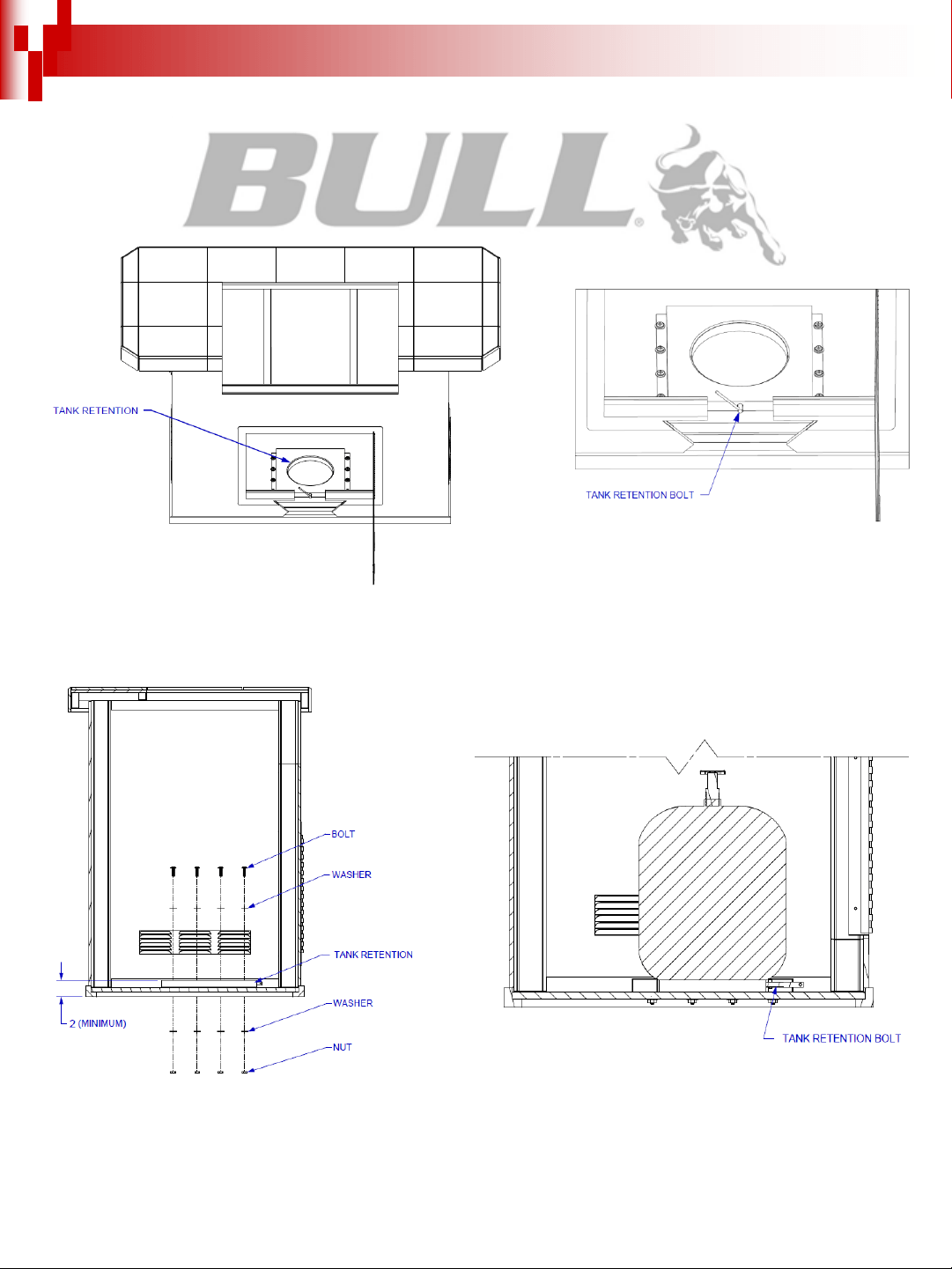
LP GAS TANK RETENTION
If using a LP gas tank, the tank must be properly secured within the structure to prevent being knocked over.
The tank retention system must be securely fastened to the bottom of the island with the use of bolts, washers and nuts. There must be a minimum
clearance of 2” between the floor and the cylinder enclosure. Once secured, place the LP tank in the tank retention system and tighten the tank
retention bolt until the tank is snug and cannot move.
9
INSPECTING I CLEANING BURNERS AND GAS
VALVES
By following these cleaning procedures on a timely basis, your slide-in double sideburner will be kept clean and working properly with minimum
effort.
CAUTION – Always turn off the gas supply prior to clearing your double sideburner.
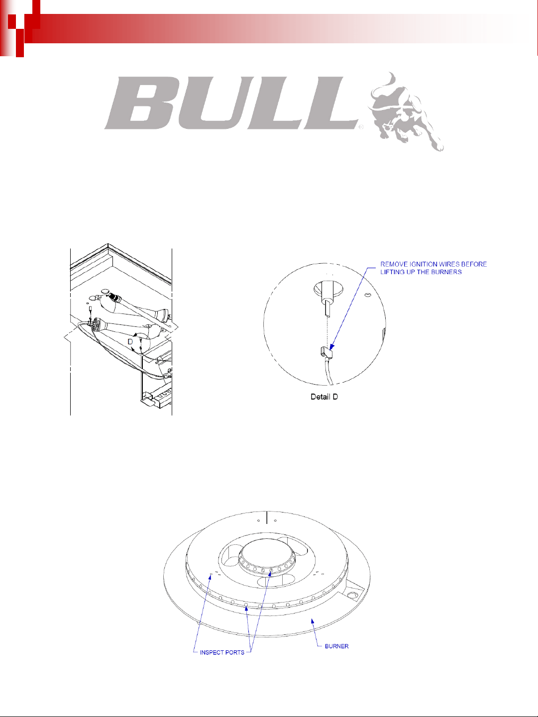
BURNER CLEANING
1. Remove burner from the double sideburner insert. Make sure to remove the ignition wires from the bottom before lifting up the burners (See
drawing below).
2. Using a narrow bottlebrush with a flexible handle, run it through the burner tube several times.
3. Inspect the burner assembly for any openings caused by corrosion.
4. Inspect the burner ports and clear any clogged ports with a stiff metal wire.
10
INSPECTING / CLEANING BURNERS AND GAS
VALVES (CONT.)
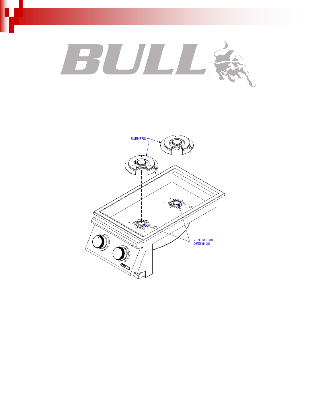
BURNER REPLACEMENT INTO INSERT
CAUTION – Always turn off the gas supply prior to clearing your double sideburner.
1. Replace burners back into the double sideburner insert.
2. Check the burners for proper location after replacing. Make sure the tubes on the bottom of the burners are inside of the ventri tubes (see
drawing below). If the burner tubes are not seated inside the ventri tubes, lighting the burners may cause explosion and/or fire.
IGNITER CHECK
With the control knobs set to “OFF”, check the first igniter for presence of spark at burner. Push control knob in fully and turn slowly about a 1/4
turn to the left (counter-clockwise) until a click is heard; the trigger hitting the strike block should produce a blue spark at the igniter tip. Return
control knob to “OFF”. Check the other igniter using the same procedure.
BURNER OPERATION CHECK
NOTE: Upon first assembly the gas lines and burners will be full of air. In order for the burners to light properly the lines must fill with gas. It may
require several attempts at lighting the burners before you are successful.
1. With the double sideburner control knobs in the “OFF” position, turn on the Gas supply.
11
INSPECTING / CLEANING BURNERS AND GAS
VALVES (CONT.)
2. Light the burner by pushing its control knob in fully and slowly (3 to 4 seconds) turning it about 1/4 turn to the left (counter-clockwise) until a click
is heard. The 3 to 4 second duration should provide enough gas to light the burner. If the burner does not light, immediately return the control knob
to “OFF”, wait several minutes for the gas to disperse, and repeat the process. After burner lights successfully, turn control knob to “OFF”. Repeat
the procedure to check the other burner.
3. If the burner(s) fails to light after several attempts, discontinue gas supply at source and re-inspect for obstructions to gas flow and orifices.
COOKING COMPONENT
IMPORTANT: Before first use: wash cooking grid with warm, soapy water. Rinse and dry thoroughly. Season metal surfaces with cooking oil
occasionally. (After cooking is completed, turn station to high setting for NO MORE THAN five minutes to burn off excess grease or food residue).
NOW YOUR SLIDE-IN DOUBLE SIDEBURNER IS READY TO USE!
Before first use and at the beginning of each barbecue season:
1. Please read Safety, Lighting and Operating Instructions carefully.
2. Check gas valves, orifices, burner tubes and burner ports for any obstructions.
3. PERFORM GAS LEAK CHECK – REFER TO PAGE 2.
12

LIGHTING & OPERATING INSTRUCTIONS
CAUTION: TO ENSURE YOUR SAFETY, DO NOT OPERATE DOUBLE SIDEBURNER UNTIL YOU FULLY READ AND UNDERSTAND THE
INSTRUCTIONS.
LIGHTING PROCEDURES
Lighting Burner:
1. Become familiar with the safety guidelines at the front of the manual. DO NOT SMOKE WHILE LIGHTING DOUBLE SIDEBURNER OR
CHECKING GAS SUPPLY CONNECTIONS!
2. If your double sideburner fuel source is a LP gas cylinder, check to see that cylinder is filled.
3. Check that the burner tubes are properly seated inside the ventri tubes.
4. Make sure all gas connections are securely tightened. TEST FOR LEAKS WITH A SOAP SOLUTION, NEVER WITH A FLAME. (Gas Leak
Check instructions are on page 2).
5. Always remove lid before lighting.
6. Set control knobs to “OFF” and open gas supply, LP cylinder or natural gas valve.
7. To ignite the burner(s): Push in control knob completely and rotate slowly (3 to 4 seconds) about 1/4 turn to the left (counter clockwise) until a
click is heard. The 3 to 4 second duration should provide enough gas to light the burner. If the burner does not light, immediately return the control
knob to ‘OFF’, wait several minutes for the gas to disperse, and repeat the process.
8. Adjust control knob(s) to desired cooking temperature.
NOTE: If igniter(s) fails to produce a spark at the electrode tip, burner can be manually lit with a fireplace-type match.
NOTE: To light the double sideburner with a fireplace-type match, follow steps 1 through 6 above. Remove cooking grid and insert lighted
fireplace-type match or long-necked butane lighter placing flame near to burner ports. Press in control knob(s) and rotate left to “HIGH” setting to
release gas. Burner(s) should light immediately. Replace cooking grid and adjust burner(s) to desired cooking temperature.
OPERATING PROCEDURE
Burn-off: Before cooking on your double sideburner for the first time, burn the double sideburner to get rid of any odors or foreign matter by
igniting the burners and operating at “HIGH” setting for about five minutes. You may then either set the control to “OFF” or cook on your double
sideburner immediately by turning the control knob(s) to a lower setting.
CAUTION: DO NOT LEAVE SLIDE-IN DOUBLE SIDEBURNER UNATTENDED WHILE IN USE.
Preheating: It is necessary to preheat the double sideburner for a short time before cooking certain foods, depending on the type of food and the
cooking temperature. Food that requires a high cooking temperature needs to preheat for five minutes; food that requires a lower cooking
temperature needs only a period of two to three minutes.
CAUTION: The minimum and maximum pot sizes to be used are between 4 3/4in(120mm)-8 3/4in(220mm) in diameter.
It is recommended you use protective gloves to operate the sideburner when handling any components with transferred heat temperature.
Do not move the appliance when it is in use.
Turn off the gas supply source after usage.
WARNING: Any modification of the appliance may be dangerous.
13

CLEANING & MAINTENANCE
CAUTION: ALWAYS ALLOW THE SLIDE-IN DOUBLE SIDEBURNER TO COOL COMPLETELY BEFORE CLEANING.
CLEANING THE COOKING GRID
After cooking, turn control knob(s) to “OFF” and let double sideburner cool before attempting to clean your cooking grid. Before first use and
periodically it is suggested that you wash the cooking grid in a mild soap and warm water solution. You can use a washcloth or a vegetable brush
to clean your cooking grid.
CLEANING THE BURNERS
IMPORTANT: Gas control knobs should be in the “OFF” position, and fuel line should be disconnected from gas valve manifold. To reduce the
chance of FLASHBACK, the procedure below should be followed at least once a month or when your double sideburner has not been used for an
extended period of time.
1. Remove burners from the double sideburner insert by carefully lifting the burners away from the ventri tubes (refer to page 8).
2. Wire brush entire outer surface of burner to remove residue and dirt. Clean any clogged orifices and/or burner ports with a stiff wire such as an
open paper clip.
3. Inspect the burners for damage (cracks or holes) and if such damage is found, order and install a new burner.
4. After installation, check to ensure that the burner tubes are correctly placed inside the ventri tubes. Also check position of spark electrode.
ANNUAL CLEANING OF DOUBLE SIDEBURNER HOUSING
Periodically the double sideburner should be given an entire thorough cleaning to ensure optimal performance.
1. Shut off gas supply at source and disconnect fuel line from gas valve manifold. Protect fuel line fitting.
2. Remove and clean the cooking grid as explained above.
3. Cover the gas orifices with a piece of aluminum foil.
4. Brush the inside and bottom of the double sideburner with a stiff wire brush, and wash down with a mild soap and warm water solution. Rinse
thoroughly and let dry.
5. Remove aluminum foil from the orifices and check for obstruction.
6. Check igniter as instructed on page 9.
7. Replace cooking grid.
8. Reconnect to gas source and observe burner flame for correct operation.
IMPORTANT: You should NOT line the bottom of the double sideburner housing with aluminum foil, sand or any other grease absorbent
substance. A fire could occur.
STAINLESS STEEL CLEANING AND MAINTENANCE
Stainless steel is a corrosion resistant chromium/nickel alloy steel that is both durable as well as strong with an outstanding luster. The goal of your
cleaning and maintenance routine should be to keep the stainless steel’s protective chromium oxide layer intact. This is what prevents corrosion.
Contrary to popular belief, stainless steel is NOT rustproof, especially in the environment of a swimming pool. Chlorine, bromine, some fertilizers
and other elements are extremely caustic chemicals for stainless steel. These chemicals combined with heat and humidity greatly increase the
corrosiveness of these chemicals. Regular cleaning is the best way to prevent corrosion and add years of enjoyment to your Bull stainless steel
products.
14
TROUBLESHOOTING
IF SLIDE-IN DOUBLE SIDEBURNER FAILS TO OPERATE PROPERLY
1. Turn off gas at source, turn control knob(s) to “OFF”, and wait five minutes before trying again.
2. Check gas supply/connections.
3. Repeat lighting procedure.
If double sideburner still fails to operate properly, TURN “OFF” GAS AT SOURCE, TURN CONTROL KNOBS TO “OFF”, wait for double
sideburner to cool, and check the following:
a. Misalignment of burner tube(s) over ventri tube(s)
CORRECTION: Reposition burner tube(s) to properly seat inside ventri tube(s).
b. Obstruction in gas line
CORRECTION: Remove fuel line from the double sideburner. DO NOT SMOKE AROUND EXPOSED GAS LINE! Open gas supply for one second
to blow any obstruction from fuel line. Close off gas supply at source and reconnect fuel line to the double sideburner.
c. Plugged orifice
CORRECTION: Remove the orifice from the ventri tube and gently clear any obstruction with a fine wire. Re-install the orifice onto ventri tube. If an
obstruction is suspected in the gas valve or the ventri tube, please contact your slide-in double sideburner dealer or gas appliance service person
for assistance.
d. Misalignment of igniter on burner
CORRECTION: Check for proper position of igniter tip. The tip of the igniter should be relatively close to the burner ports and free from grease for
spark discharging. The ignition wire should be firmly connected to the valve ignition and igniter. Replace the ignition wire if the wire were broken or
cracked. With gas supply closed and the control knobs set to “OFF”, check the positive igniter individually for presence of spark at igniter tip. Push
the control knob in fully and rotate about 1/4 turn to the left (counter-clockwise) until click is heard; the trigger hitting the strike block should produce
a blue spark at the igniter tip. Return control knob to “OFF”.
If re-ignition is necessary
While the double sideburner is still hot, you must wait for a minimum of five minutes before commencing to re-ignite (this allows accumulated gas
fumes to clear). If all checks/corrections have been made and the double sideburner still fails to operate properly, consult your double sideburner
dealer or gas appliance service person.
FLASHBACK
When fire occurs in and around the burner tube(s), immediately turn off gas at its source and turn the control knob(s) to “OFF”. Wait until the
double sideburner has cooled completely, then clean the burner tube(s) as described on page 8.
15
REGISTERING YOUR SIDEBURNER
To validate your Bull Limited Warranty, you
must submit the completed the Warranty
Registration Card within 90 days from the
date of purchase. Registration can be
completed on-line at www.bullbbq.com or by
sending the completed Warranty Registration
Card and copy of your Purchase Receipt or
Invoice as proof of purchase to:
BULL OUTDOOR PRODUCTS, INC.
1011 East Pine St.
Lodi, CA 95240
Attn: Warranty Service Center
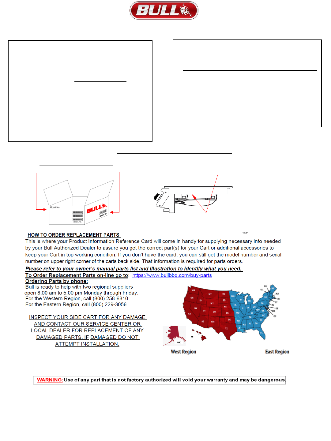
MODEL AND
SERIAL NUMBER LOCATIONS
SIDES OF THE SHIPPING BOXX
UNDERSIDE OF SIDEBURNER FRAME
1) Model
Number_____________________________
2) Date of Purchase______________________
3) Copy of your Purchase Receipt or Invoice.
For Warranty Questions call Customer
Service at
(800) 521-2855
For Warranty Claims or Replacement Parts
ordering, please fill out the area provided
below:
PRODUCT INFORMATION REFERENCE CARD
16
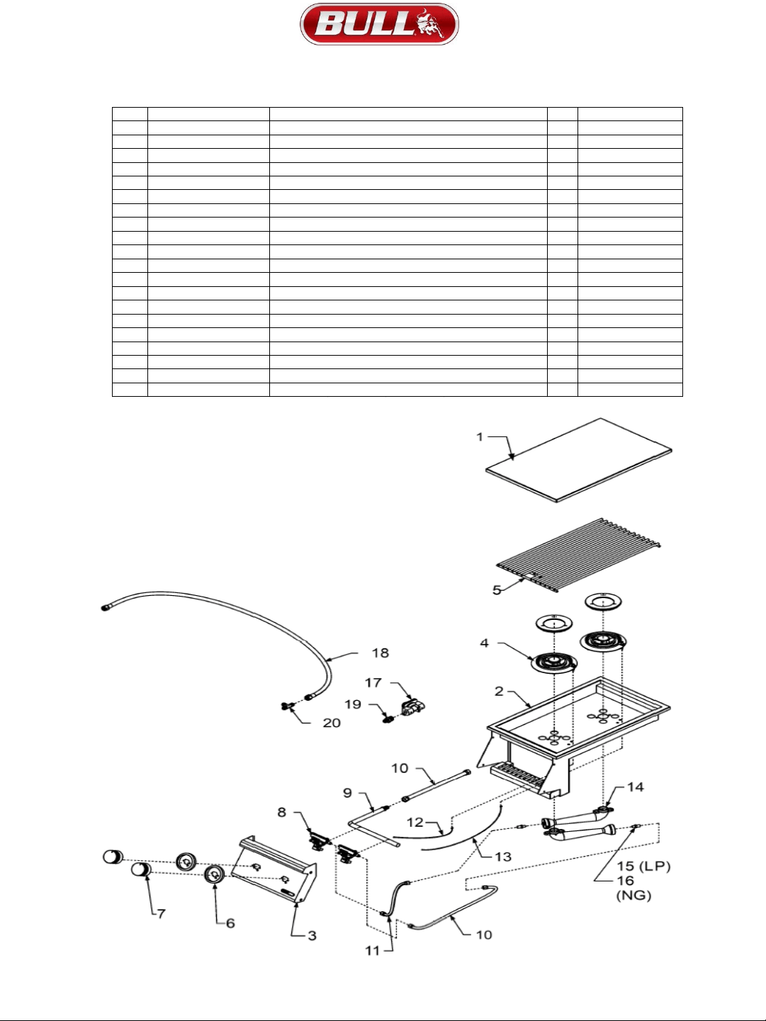
REPLACEMENT PARTS LIST AND ILLUSTRATION
MODEL #30008 SLIDE-IN DOU
BLE SIDEBURNER STAINLESS STEEL, BUILT-IN, L.P. (PROPANE)
MODEL #30009 SLIDE-IN DOUBLE SIDEBURNER STAINLESS STEEL, BUILT-IN, N.G. (NATURAL GAS)
17
REF
#
PARTS # QTY WARRANTY PERIOD
1 95000 1 1 Yr
2 30019 1 5 Yrs
3 30011 1 1 Yr
4 18359 2 3 Yrs
5
95005
1
Lifetime
6 16629
2
1 Yr
7
16613
2
1 Yr
8 16526
2
1 Yr
9
30012
1
3 Yrs
10
47006
2
1 Yr
11 95011
1
1 Yr
12
30013
1
1 Yr
13
30014
2
1 Yr
14
18058
2
1 Yr
15
30017 NG
2
1 Yr
17
16507 1
1 Yr
18
16544 1
1 Yr
19 16599 1
1 Yr
20 16510 1 1 Yr
NG REGULATOR - NATURAL GAS MODEL ONLY
IGNITION WIRE (LONG)
REGULATOR ADAPTER - NATURAL GAS MODEL ONLY
ORIFICE LP
VENTRI TUBE
STAINLESS STEEL SIDEBURNER
BEZEL
INSERT ASSEMBLY
COOKING GRATE
CONTROL PANEL
STAINLESS FLEX TUBE 8"
IGNITION WIRE (SHORT)
TEE FITTING - LIQUID PROPANE MODEL ONLY
SIDEBURNER LP HOSE - LIQUID PROPANE MODEL ONLY
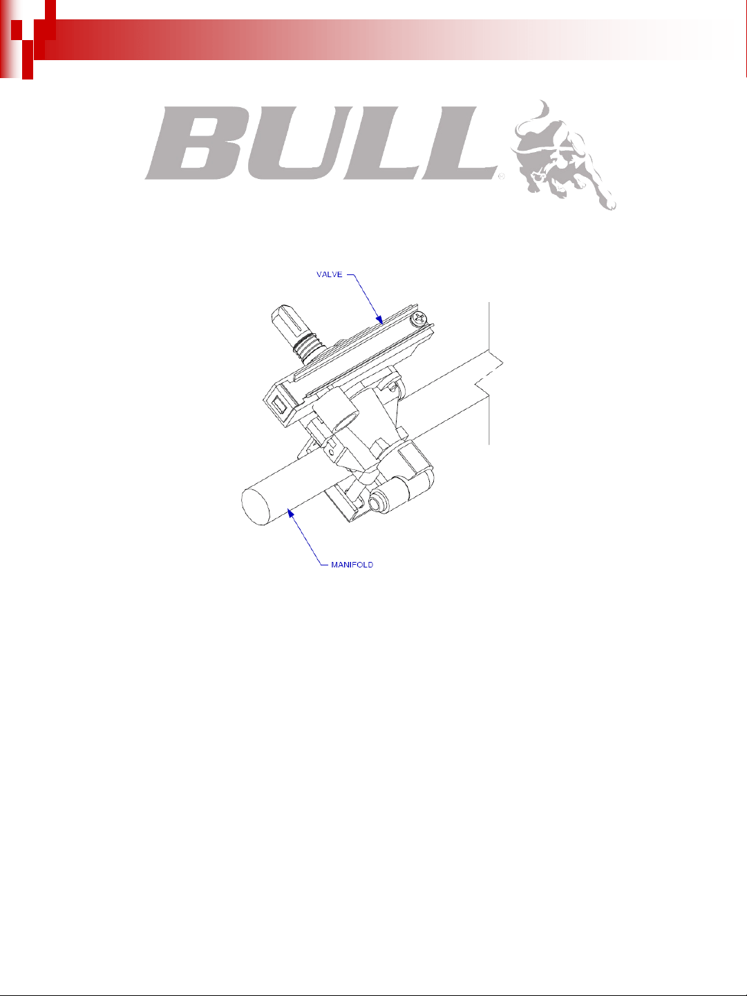
GAS VALVE - BURNER
KNOB
MANIFOLD
STAINLESS FLEX TUBE 18"
DESCRIPTION
COVER LID
30016 LP
ORIFICE NG
16
1 Yr
2

Warranty Policy
LIMITED WARRANTY ON BULL OUTDOOR PRODUCTS, INC., PRODUCTS
THIS LIMITED WARRANTY GIVES YOU SPECIFIC LEGAL RIGHTS. YOU MAY ALSO HAVE OTHER
RIGHTS, WHICH VARY FROM STATE TO STATE.
THIS LIMITED WARRANTY CAN ALSO BE FOUND ON OUR WEB SITE AT:
https://www.bullbbq.com/support-warranty (United States Customers);
https://www.bullbbq.eu/en/warrantyform.htm (International Customers)
AND IN THE OWNER’S/INSTALLATION MANUAL THAT WE PROVIDE
WITH OUR PRODUCT.
THIS LIMITED WARRANTY IS SUBJECT TO THE EXCLUSIONS, CONDITIONS AND LIMITATIONS
SET FORTH BELOW.
ANY IMPLIED WARRANTIES IMPOSED BY LAW, INCLUDING WITHOUT LIMITATION THE
IMPLIED WARRANTIES OF MRECHANTABILITY AND FITNESS FOR A PARTICULAR PURPOSE,
ARE LIMITED IN DURATION TO THE DURATION OF THIS EXPRESS LIMITED WARRANTY. SOME
STATES DO NOT ALLOW LIMITATIONS ON HOW LONG AN IMPLIED WARRANTY LASTS, SO THE
ABOVE LIMITATION MAY NOT APPLY TO YOU.
WHO MAY USE THIS WARRANTY?
BULL OUTDOOR PRODUCTS, INC. located at address 1011 East Pine St. Lodi, CA. 95240
("we") extend this limited warranty only to the consumer who originally purchased the product
("you") at the original site of delivery or installation. It does not extend to any subsequent owner or
other transferee of the product. It does not apply to products installed in any rental, commercial or
non-residential application. Examples of excluded applications include, but are not limited to day
care centers, schools, bed and breakfast centers, churches, private clubs, fire stations, club houses,
common areas in multi-family dwellings, restaurants, hotels, nursing homes, food service locations
and institutional food service locations.
WHAT DOES THIS WARRANTY COVER?
This limited warranty covers defects in materials and workmanship of the product and product
components identified below for the Warranty Periods defined below.
WHAT IS THE PERIOD OF COVERAGE?
This limited warranty starts on the date of your purchase and lasts for the time period or time periods
specified above (the "Warranty Period"). The Warranty Period is not extended if we repair or
replace the product. We may change the availability of this limited warranty at our discretion, but
any changes will not be retroactive.
Page 18

Grill Warranty Periods
The following parts are covered for one year on all our current gas grill models:
The lid, control panel, grease tray, bezels, knobs, temperature gauge, valves, regulator, flex tubes,
rotisserie burner, transformer, and all components of the lighting system.
The following parts are covered for three years on all our current gas grill models:
The manifold, handle end caps, flame tamers, heat shields, and warming rack.
The following parts are covered for lifetime on all our current gas grill models:
Insert assembly and the grates.
The warranty period for the grill burners vary by type:
Cast stainless steel burners - lifetime,
Welded burners – 5 years, and
Porcelain coated burners – 3 years.
The warranty period for the charcoal grill is one year on all parts, except for the insert assembly,
which is covered for 5 years.
The Bel Air grill included a one‐year warranty on all parts.
Component Warranty Periods
All of the parts for our components/grill carts/refrigerators/kegerators/drawers/doors are
covered for one year with these exceptions:
Power Burner
o The insert/grates are lifetime covered parts.
o The manifold/burner are covered for 3 years.
Searing Station/Slide in Double Sideburner
o The grates are covered for lifetime,
o the insert for 5 years, and
o the manifold for 3 years.
Single Sideburner
o The grates are covered for 5 years and
o the burner for 3 years.
Sidekick
o The burner is covered for 3 years.
Pizza Ovens/Islands/Fire Features Warranty Periods
All of the parts and construction materials are covered for one year.
Grill Accessories and Grill Covers do not include a warranty period.
Page 199

WHAT DOES THIS WARRANTY NOT COVER?
This limited warranty does not cover any damage due to: (a) transportation; (b) storage; (c)
improper installation or use; (d) use on improper fuel/gas supply; (e) failure to follow the
product instructions or to perform any preventive maintenance; (f) modifications; (g)
unauthorized repair; (h) normal wear and tear; or (i) external causes such as accidents, abuse,
or other actions or events beyond our reasonable control.
WHAT ARE YOUR REMEDIES UNDER THIS WARRANTY?
With respect to any defective product claim made during the Warranty Period, we will, in our
sole discretion, either: repair or replace such product (or the defective part) free of charge or
(b) refund the purchase price of such product. We will not pay for shipping charges for repaired
or replacement parts, or for any labor or labor related charges. We will not pay for any
accessory products or ancillary products purchased by you for use in connection with the
product.
HOW DO YOU OBTAIN WARRANTY SERVICE?
To obtain warranty service, you must submit a warranty claim online through the Bullbq.com
website during the Warranty Period.
Warranty claims will not be accepted via email, fax or
phone.
LIMITATION OF LIABILITY
THE REMEDIES DESCRIBED ABOVE ARE YOUR SOLE AND EXCLUSIVE REMEDIES AND OUR
ENTIRE LIABILITY FOR ANY BREACH OF THIS LIMITED WARRANTY. OUR LIABILITY
SHALL UNDER NO CIRCUMSTANCES EXCEED THE ACTUAL AMOUNT PAID BY YOU FOR
THE DEFECTIVE PRODUCT, NOR SHALL WE UNDER ANY CIRCUMSTANCES BE LIABLE FOR
ANY CONSEQUENTIAL, INCIDENTAL, SPECIAL OR PUNITIVE DAMAGES OR LOSSES,
WHETHER DIRECT OR INDIRECT.
SOME STATES DO NOT ALLOW THE EXCLUSION OR LIMITATION OF INCIDENTAL OR
CONSEQUENTIAL DAMAGES, SO THE ABOVE LIMITATION OR EXCLUSION MAY NOT
APPLY TO YOU.
Revised 10-15-2020 APR
Page 20