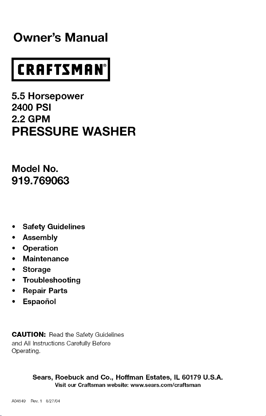
Owner's Manual
I CRRFTSMRNq
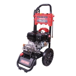
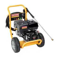
5.5 Horsepower
2400 PSI
2.2 GPM
PRESSURE WASHER
Model No.
919.769063
• Safety Guidelines
• Assembly
• Operation
• Maintenance
• Storage
• Troubleshooting
• Repair Parts
• Espao_ol
CAUTION: Read the Safety Guidelines
and All Instructions Carefully Before
Operating.
Sears, Roebuck and Co., Hoffman Estates, IL 60179 U.S.A.
visit our craftsman website: www.sears.com/craftsman
A04549 Rev. 1 8/27/04
kf;_ :] ml=1[o]_[_o] _i nl=1_k_'_
WARRANTY ................................................ 2
SPECIFICATION CHART ..................................... 3
SAFETY GUIDELINES- DEFINITIONS ........................... 3
IMPORTANT SAFETY INSTRUCTIONS ........................ 3-7
BOX CONTENTS ............................................ 7
ASSEMBLY ................................................ 8
OPERATION ............................................. 9-13
MAINTENANCE ......................................... 13-16
STORAGE .............................................. 17-18
TROUBLESHOOTING GUIDE .............................. 18-20
REPAIR PARTS ......................................... 21-36
HOW TO ORDER REPAIR PARTS ...................... Back Cover
kvAv/_,l;I;:El(Nmk'd
FULL ONE YEAR WARRANTY ON CRAFTSMAN HIGH PRESSURE WASHER
For one year from the date of purchase, when this Craftsman High Pressure
Washer is maintained and operated according to the instructions in the owner's
manual, Sears will repair, free of charge, any defect in material and workmanship.
If your Craftsman Pressure Washer is used for commercial or rental purposes, this
warranty applies only for 90 days from the date of purchase.
FULL TWO YEAR WARRANTY ON CRAFTSMAN ENGINE
For two years from the date of purchase, when this Craftsman engine is maintained
and operated according to the instructions in the owner's manual, Sears will repair,
free of charge, any defect in material and workmanship.
If your Craftsman engine is used for commercial or rental purposes, this warranty
applies only for 90 days from the date of purchase. This warranty does not cover
expendable items such as spark plugs and air filters, which become worn during
normal use.
Repairs necessary because of operator abuse or negligence, including damage
resulting from no water being supplied to pump or failure to maintain the
equipment according to the instructions contained in the owner's manual, are not
covered under warranty.
WARRANTY SERVICE IS AVAILABLE BY RETURNING THE HIGH PRESSURE
WASHER TO THE NEAREST SEARS SERVICE CENTER THROUGHOUT THE
UNITED STATES. This warranty gives you specific legal rights and you may also
have other rights, which vary from state to state.
Sears, Roebuck and Co., D/817 WA, Hoffman Estates, IL 60179
A_54e 2-ENG
[...__o,][2ijI[o]_[ Eo,]:r:_:Vnl
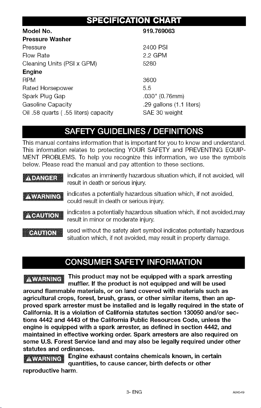
Model No. 919.769063
Pressure Washer
Pressure 2400 PSI
Flow Rate 2.2 GPM
Cleaning Units (PSI x GPM) 5280
Engine
RPM 3600
Rated Horsepower 5.5
Spark Plug Gap .030" (0.76mm)
Gasoline Capacity .29 gallons (1.1 liters)
Oil .58 quarts ( .55 liters) capacity SAE 30 weight
This manual contains information that is important for you to know and understand.
This information relates to protecting YOUR SAFETY and PREVENTING EQUIP-
MENT PROBLEMS. To help you recognize this information, we use the symbols
below. Please read the manual and pay attention to these sections.
indicates an imminently hazardous situation which, if not avoided, will
result in death or serious injury.
indicates a potentially hazardous situation which, if not avoided,
could result in death or serious injury.
indicates a potentially hazardous situation which, if not avoided,may
result in minor or moderate injury.
used without the safety alert symbol indicates potentially hazardous
situation which, if not avoided, may result in property damage.
This product may not be equipped with a spark arresting
muffler. If the product is not equipped and will be used
around flammable materials, or on land covered with materials such as
agricultural crops, forest, brush, grass, or other similar items, then an ap-
proved spark arrester must be installed and is legally required in the state of
California. It is a violation of California statutes section 130050 and/or sec-
tions 4442 and 4443 of the California Public Resources Code, unless the
engine is equipped with a spark arrester, as defined in section 4442, and
maintained in effective working order. Spark arresters are also required on
some U.S. Forest Service land and may also be legally required under other
statutes and ordinances.
Engine exhaust contains chemicals known, in certain
quantities, to cause cancer, birth defects or other
reproductive harm,
3- ENG A04549
Do not operate this unit until you have read and understand this
Operators Manual and the Engine Owners Manual for Safety,
Operation, and Maintenance Instructions.
READ AND SAVE THESE INSTRUCTIONS
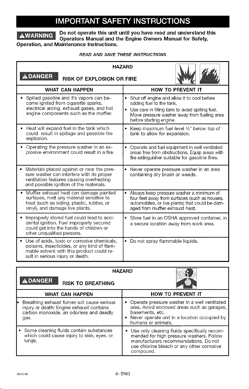
HAZARD
RISK OF EXPLOSION OR FIRE
WHAT CAN HAPPEN
• Spilled gasoline and it's vapors can be- •
come ignited from cigarette sparks,
electrical arcing, exhaust gases, and hot •
engine components such as the muffler.
• Heat will expand fuel in the tank which •
could result in spillage and possible fire
explosion.
• Operating the pressure washer in an ex- •
plosive environment could result in a fire.
• Materials placed against or near the pres- •
sure washer can interfere with its proper
ventilation features causing overheating
and possible ignition of the materials.
• Muffler exhaust heat can damage painted •
surfaces, melt any material sensitive to
heat (such as siding, plastic, rubber, or
vinyl), and damage live plants.
• Improperly stored fuel could lead to acci- •
dental ignition. Fuel improperly secured
could get into the hands of children or
other unqualified persons.
• Use of acids, toxic or corrosive chemicals, •
poisons, insecticides, or any kind of flam-
mable solvent with this product could re-
sult in serious injury or death.
HOW TO PREVENT IT
Shut off engine and allow it to cool before
adding fuel to the tank.
Use care in filling tank to avoid spilling fuel.
Move pressure washer away from fueling area
before starting engine.
Keep maximum fuel level 1/2' below top of
tank to allow for expansion.
Operate and fuel equipment in well ventilated
areas free from obstructions. Equip areas with
fire extinguisher suitable for gasoline fires.
Never operate pressure washer in an area
containing dry brush or weeds.
Always keep pressure washer a minimum of
four feet away from surfaces (such as houses,
automobiles, or live plants) that could be dam-
aged from muffler exhaust heat.
Store fuel in an OSHA approved container, in
a secure location away from work area.
Do not spray flammable liquids.
HAZARD
RISK TO BREATHING
WHAT CAN HAPPEN
Breathing exhaust fumes will cause serious
injury or death] Engine exhaust contains
carbon monoxide, an odorless and deadly
gas.
• Some cleaning fluids contain substances
which could cause injury to skin, eyes, or
lungs.
HOW TO PREVENT IT
• Operate pressure washer in a well ventilated
area. Avoid enclosed areas such as garages,
basements, etc.
• Never operate unit in a location occupied by
humans or animals.
• Use only cleaning fluids specifically recom-
mended for high pressure washers. Follow
manufacturers recommendations. Do not
use chlorine bleach or any other corrosive
compound.
A04549 4- ENG
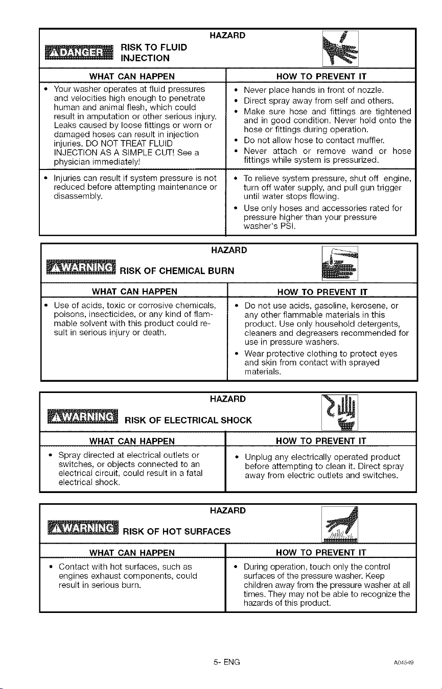
RISK TO FLUID
INJECTION
HAZARD
WHAT CAN HAPPEN
• Your washer operates at fluid pressures
and velocities high enough to penetrate
human and animal flesh, which could
result in amputation or other serious injury.
Leaks caused by loose fittings or worn or
damaged hoses can result in injection
injuries. DO NOT TREAT FLUID
INJECTION AS A SIMPLE CUT] See a
physician immediately]
• Injuries can result if system pressure is not
reduced before attempting maintenance or
disassembly.
HOW TO PREVENT IT
• Never place hands in front of nozzle.
• Direct spray away from self and others.
• Make sure hose and fittings are tightened
and in good condition. Never hold onto the
hose or fittings during operation.
• Do not allow hose to contact muffler.
• Never attach or remove wand or hose
fittings while system is pressurized.
• To relieve system pressure, shut off engine,
turn off water supply, and pull gun trigger
until water stops flowing.
• Use only hoses and accessories rated for
pressure higher than your pressure
washer's PSI.
HAZARD
RISK OF CHEMICAL BURN
WHAT CAN HAPPEN
• Use of acids, toxic or corrosive chemicals,
poisons, insecticides, or any kind of flam-
mable solvent with this product could re-
sult in serious injury or death.
HOW TO PREVENT IT
• Do not use acids, gasoline, kerosene, or
any other flammable materials in this
product. Use only household detergents,
cleaners and degreasers recommended for
use in pressure washers.
• Wear protective clothing to protect eyes
and skin from contact with sprayed
materials.
HAZARD
RISK OF ELECTRICAL SHOCK
WHAT CAN HAPPEN HOW TO PREVENT IT
• Spray directed at electrical outlets or • Unplug any electrically operated product
switches, or objects connected to an before attempting to clean it. Direct spray
electrical circuit, could result in a fatal away from electric outlets and switches.
electrical shock.
HAZARD
_RISK OF HOT SURFACES
WHAT CAN HAPPEN HOW TO PREVENT IT
• Contact with hot surfaces, such as • During operation, touch only the control
engines exhaust components, could surfaces of the pressure washer. Keep
result in serious burn. children away from the pressure washer at all
times. They may not be able to recognize the
hazards of this product.
5- ENG A04549
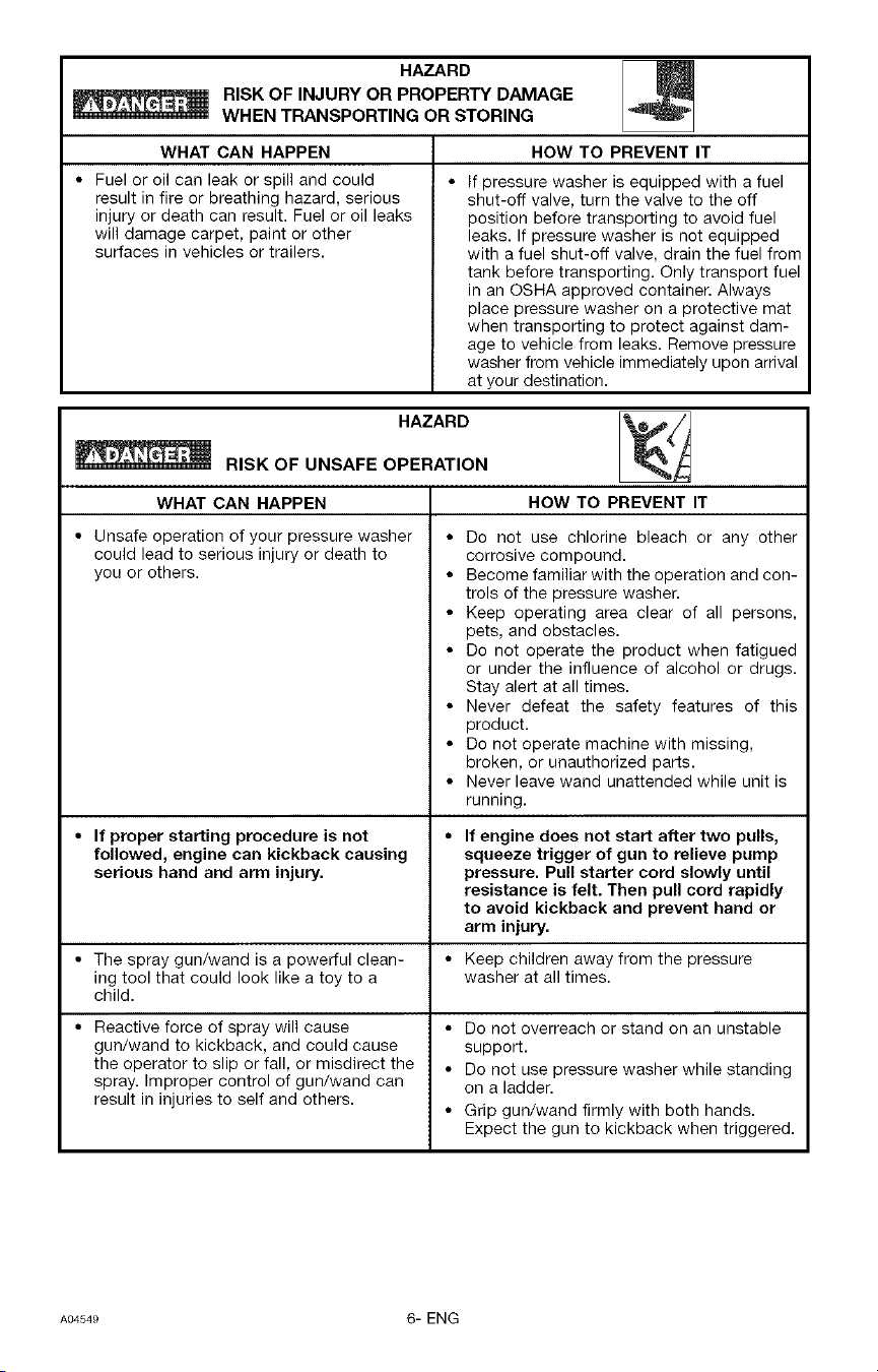
HAZARD
RISK OF INJURY OR PROPERTY DAMAGE
WHEN TRANSPORTING OR STORING
WHAT CAN HAPPEN HOW TO PREVENT IT
• Fuel or oil can leak or spill and could
result in fire or breathing hazard, serious
injury or death can result. Fuel or oil leaks
will damage carpet, paint or other
surfaces in vehicles or trailers.
If pressure washer is equipped with a fuel
shut-off valve, turn the valve to the off
position before transporting to avoid fuel
leaks. If pressure washer is not equipped
with a fuel shut-off valve, drain the fuel from
tank before transporting. Only transport fuel
in an OSHA approved container. Always
place pressure washer on a protective mat
when transporting to protect against dam-
age to vehicle from leaks. Remove pressure
washer from vehicle immediately upon arrival
at your destination.
HAZARD
RISK OF UNSAFE OPERATION
WHAT CAN HAPPEN
• Unsafe operation of your pressure washer •
could lead to serious injury or death to
you or others. •
• If proper starting procedure is not •
followed, engine can kickback causing
serious hand and arm injury.
• The spray gun/wand is a powerful clean- •
ing tool that could look like a toy to a
child.
• Reactive force of spray will cause •
gun/wand to kickback, and could cause
the operator to slip or fall, or misdirect the •
spray. Improper control of gun/wand can
result in injuries to self and others.
HOW TO PREVENT IT
Do not use chlorine bleach or any other
corrosive compound.
Become familiar with the operation and con-
trols of the pressure washer.
Keep operating area clear of all persons,
pets, and obstacles.
Do not operate the product when fatigued
or under the influence of alcohol or drugs.
Stay alert at all times.
Never defeat the safety features of this
product.
Do not operate machine with missing,
broken, or unauthorized parts.
Never leave wand unattended while unit is
running.
If engine does not start after two pulls,
squeeze trigger of gun to relieve pump
pressure. Pull starter cord slowly until
resistance is felt. Then pull cord rapidly
to avoid kickback and prevent hand or
arm injury.
Keep children away from the pressure
washer at all times.
Do not overreach or stand on an unstable
support.
Do not use pressure washer while standing
on a ladder.
Grip gun/wand firmly with both hands.
Expect the gun to kickback when triggered.
A04549 6- ENG
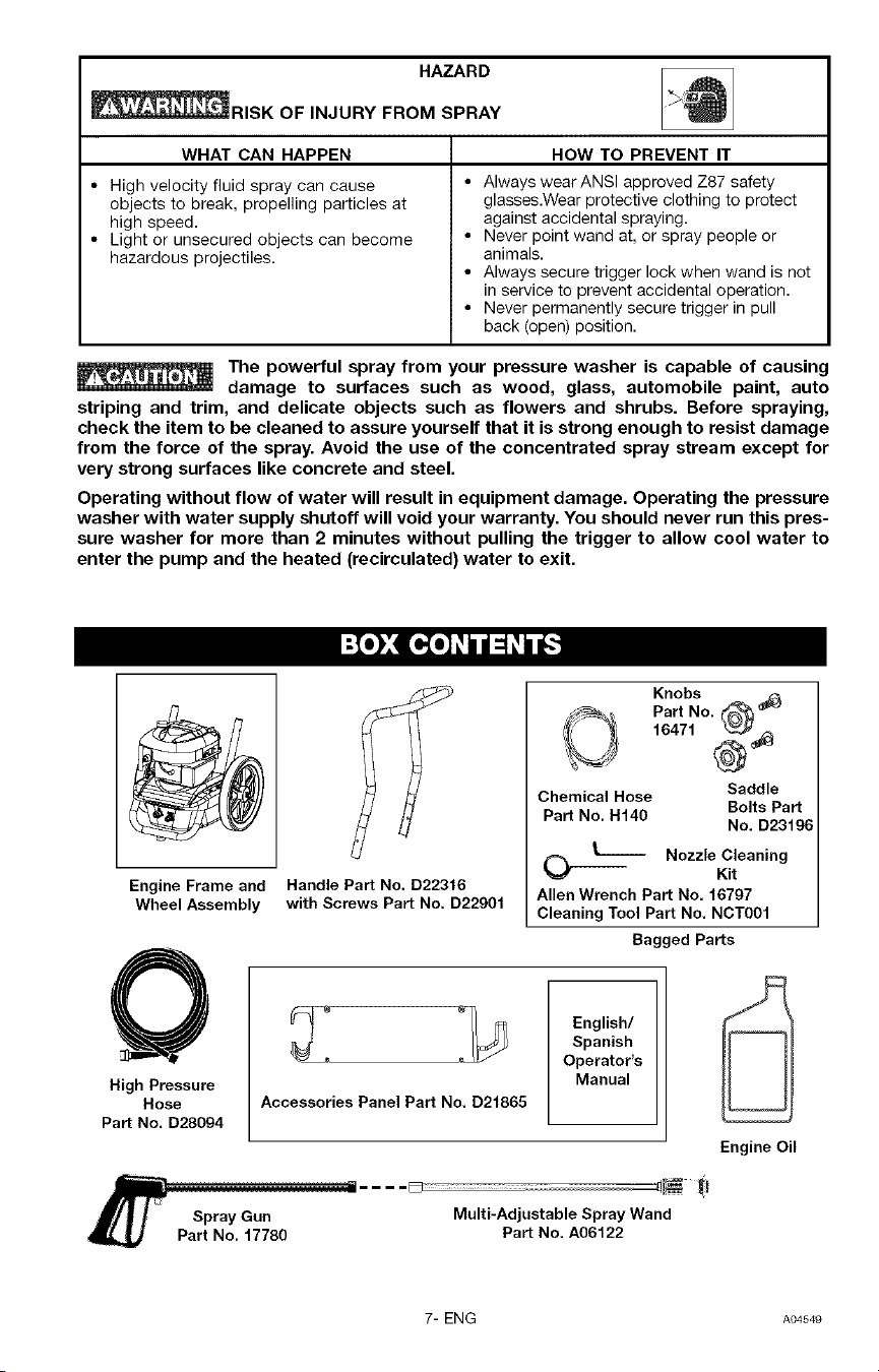
HAZARD
_91SK OF INJURY FROM SPRAY
WHAT CAN HAPPEN
• High velocity fluid spray can cause
objects to break, propelling particles at
high speed.
• Light or unsecured objects can become
hazardous projectiles.
HOW TO PREVENT IT
• Always wearANSI approved Z87 safety
glasses.Wear protective clothing to protect
against accidental spraying.
• Never point wand at, or spray people or
animals.
• Always secure trigger lock when wand is not
in service to prevent accidental operation.
• Never permanently secure trigger in pull
back (open) position.
The powerful spray from your pressure washer is capable of causing
damage to surfaces such as wood, glass, automobile paint, auto
striping and trim, and delicate objects such as flowers and shrubs. Before spraying,
check the item to be cleaned to assure yourself that it is strong enough to resist damage
from the force of the spray. Avoid the use of the concentrated spray stream except for
very strong surfaces like concrete and steel.
Operating without flow of water will result in equipment damage. Operating the pressure
washer with water supply shutoff will void your warranty. You should never run this pres-
sure washer for more than 2 minutes without pulling the trigger to allow cool water to
enter the pump and the heated (recirculated) water to exit.
Engine Frame and
Wheel Assembly
Handle Part No, D22346
with Screws Part No. D22904
Knobs
Part No. (*_
16471 _
Chemical Hose Saddle
Bolts Part
Part No. H140
No. D23196
(_ I__ Nozzle Cleaning
Kit
Allen Wrench Part No. 46797
Cleaning Tool Part No. NCT004
Bagged Parts
High Pressure
Hose
Part No. D28094
Accessories Panel Part No. D21865
English/
Spanish
Operator's
Manual
_L/F spray Gun
Part No. 47780
Multi-Adjustable Spray Wand
Part No. A06122
Engine Oil
7- ENG A04549
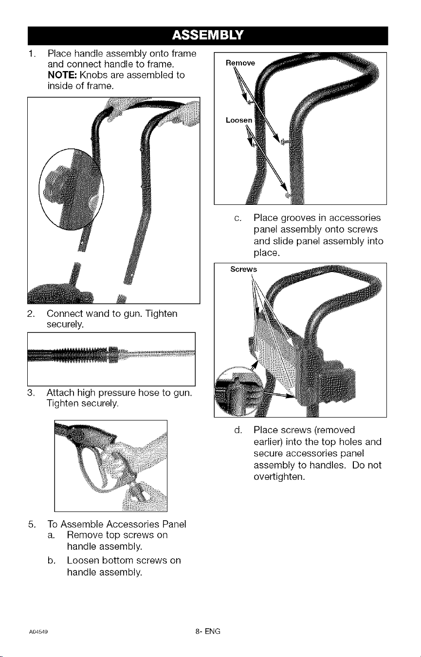
1,
Place handle assembly onto frame
and connect handle to frame.
NOTE: Knobs are assembled to
inside of frame.
Connect wand to gun. Tighten
securely.
Attach high pressure hose to gun.
Tighten securely.
Remove
Loosen
Place grooves in accessories
panel assembly onto screws
and slide panel assembly into
place.
Scows
d.
Place screws (removed
earlier) into the top holes and
secure accessories panel
assembly to handles. Do not
overtighten.
5. To Assemble Accessories Panel
a. Remove top screws on
handle assembly.
b. Loosen bottom screws on
handle assembly.
A_549 8-ENG
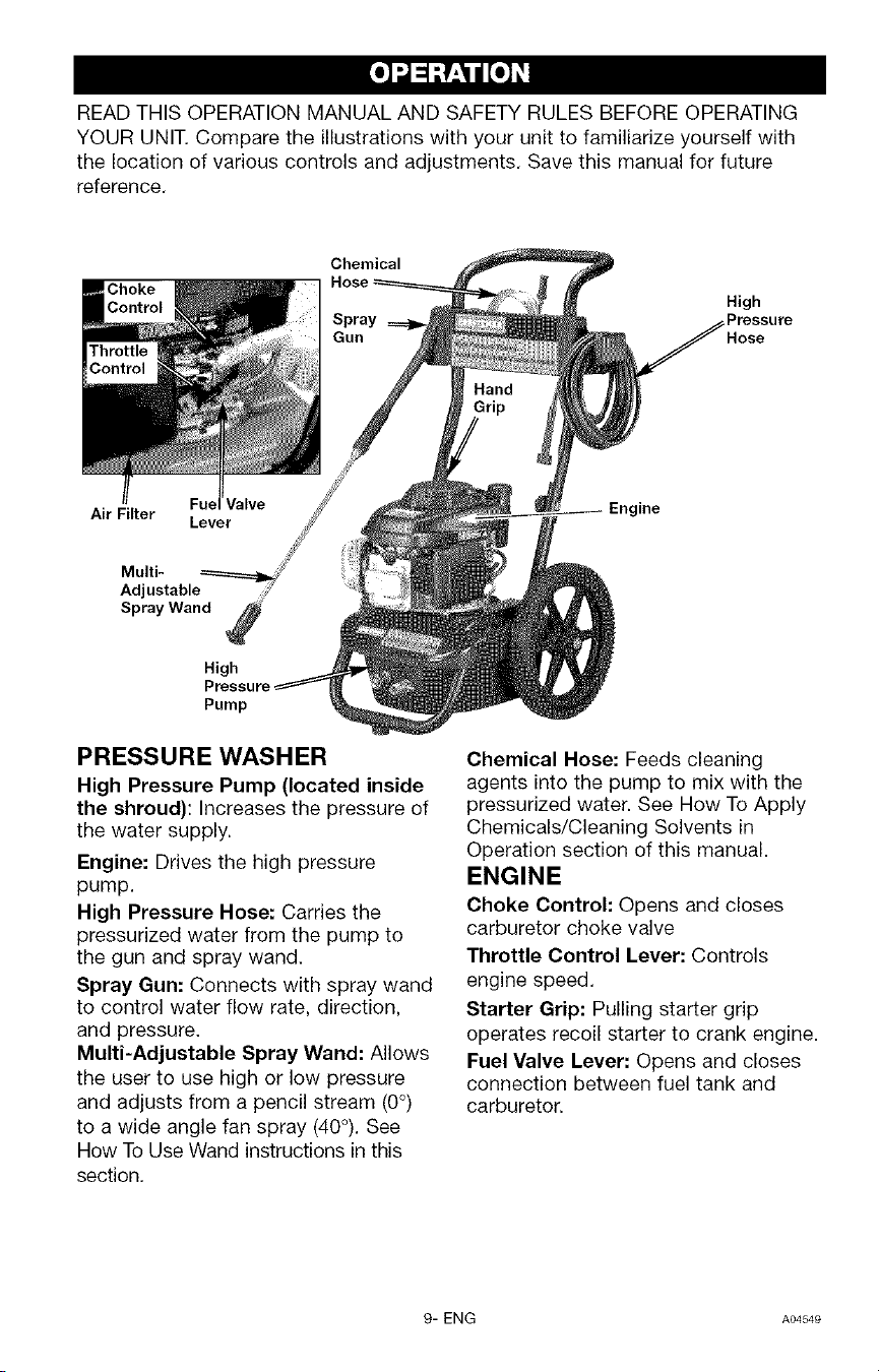
READ THIS OPERATION MANUAL AND SAFETY RULES BEFORE OPERATING
YOUR UNIT. Compare the illustrations with your unit to familiarize yourself with
the location of various controls and adjustments. Save this manual for future
reference.
Chemical
Air Filter
Lever
Multi-
Adjustable
Spray Wand
High
Pump
PRESSURE WASHER
High Pressure Pump (located inside
the shroud): Increases the pressure of
the water supply.
Engine: Drives the high pressure
pump.
High Pressure Hose: Carries the
pressurized water from the pump to
the gun and spray wand.
Spray Gun: Connects with spray wand
to control water flow rate, direction,
and pressure.
Multi-Adjustable Spray Wand: Allows
the user to use high or low pressure
and adjusts from a pencil stream (0°)
to a wide angle fan spray (40°). See
How To Use Wand instructions in this
section.
High
_Pressure
Engine
Chemical Hose: Feeds cleaning
agents into the pump to mix with the
pressurized water. See How To Apply
Chemicals/Cleaning Solvents in
Operation section of this manual.
ENGINE
Choke Control: Opens and closes
carburetor choke valve
Throttle Control Lever: Controls
engine speed.
Starter Grip: Pulling starter grip
operates recoil starter to crank engine.
Fuel Valve Lever: Opens and closes
connection between fuel tank and
carburetor.
9- ENG AO4S4e
PRESSURE WASHER
TERMINOLOGY
PSI: Pounds per Square Inch. The unit
of measure for water pressure. Also
used for air pressure, hydraulic
pressure, etc.
GPM: Gallons Per Minute. The unit of
measure for the flow rate of water.
CU: Cleaning Units. GPM multiplied by
PSI. GPM x PSI = CU
Bypass Mode: Allows water to
re-circulate within pump when the gun
trigger is not pulled.
Allowing the unit to
run for more than
two minutes without the gun trigger
pulled could cause overheating and
damage to the pump.
Chemical Injection System: Mixes
cleaners or cleaning solvents with the
water to improve cleaning
effectiveness.
Water Supply: All pressure washers
must have a source of water. The
minimum requirements for a water
supply are 20 PSI and 5 gallons per
minute.
HOW TO USE
IMPORTANT: Read and understand
how to use the pressure washer
before operating.
TO ADJUST PRESSURE
The pressure setting is preset at the
factory to achieve optimum pressure
and cleaning. If you need to lower the
pressure, it can be accomplished by
these methods.
1. Back away from the surface to
be cleaned. The further away you
are, the less the pressure will be
on the surface to be cleaned.
2. Rotate the nozzle at the end of
the multi-adjustable spray wand
to widen the fan spray. The
wider fan spray will minimize the
pressure on the surface to be
cleaned.
DO NOT attempt to
increase pump
pressure. A higher pressure setting
than the factory set pressure may
damage pump.
HOW TO USE SPRAY WAND
Your pressure washer is equipped with
a multi-adjustable spray wand with
both high and low pressure settings.
The high pressure setting is for
cleaning and rinsing, the low pressure
setting is for applying chemicals or
cleaning solutions to surfaces.
When using the high
pressure setting, DO
NOT allow the jet-like spray to come
in contact with unprotected skin,
eyes, or with any pets or animals.
Serious injury can occur.
Risk of injection or
injury to person. DO
NOT direct discharge stream toward
persons.
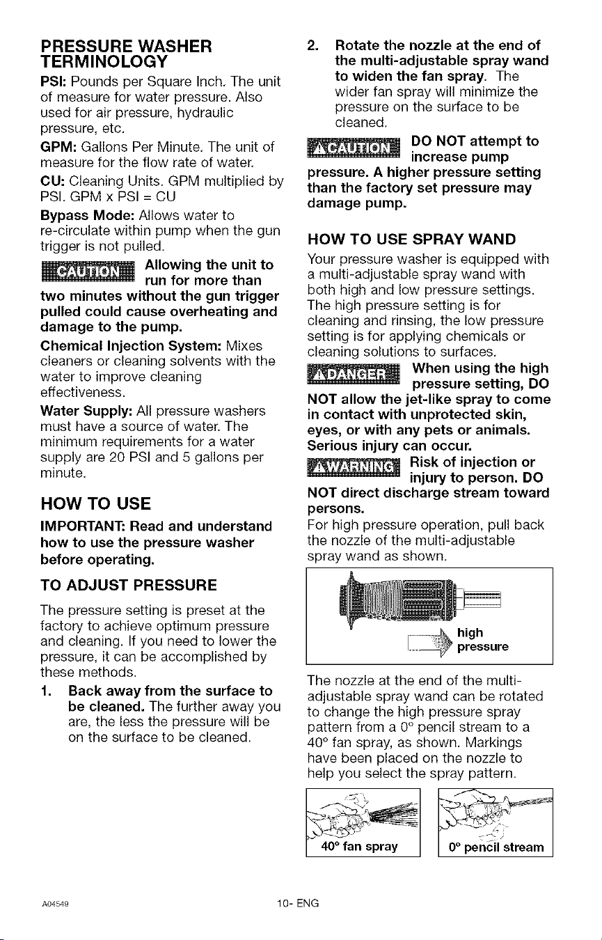
For high pressure operation, pull back
the nozzle of the multi-adjustable
spray wand as shown.
The nozzle at the end of the multi-
adjustable spray wand can be rotated
to change the high pressure spray
pattern from a 0° pencil stream to a
40° fan spray, as shown. Markings
have been placed on the nozzle to
help you select the spray pattern.
I 40° fan spray I I 0° pencil stream
A04549 10- ENG
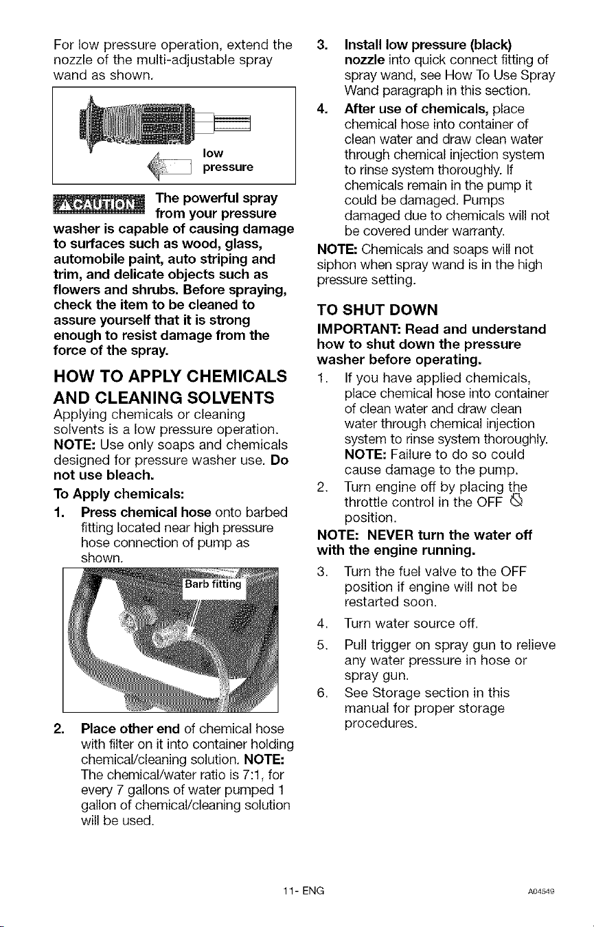
For low pressure operation, extend the
nozzle of the multi-adjustable spray
wand as shown.
low
pressure
The powerful spray
from your pressure
washer is capable of causing damage
to surfaces such as wood, glass,
automobile paint, auto striping and
trim, and delicate objects such as
flowers and shrubs. Before spraying,
check the item to be cleaned to
assure yourself that it is strong
enough to resist damage from the
force of the spray.
HOW TO APPLY CHEMICALS
AND CLEANING SOLVENTS
Applying chemicals or cleaning
solvents is a low pressure operation.
NOTE: Use only soaps and chemicals
designed for pressure washer use. Do
not use bleach.
To Apply chemicals:
1. Press chemical hose onto barbed
fitting located near high pressure
hose connection of pump as
shown.
2. Place other end of chemical hose
with filter on it into container holding
chemical/cleaning solution. NOTE:
The chemical/water ratio is 7:1, for
every 7 gallons of water pumped 1
gallon of chemical/cleaning solution
will be used.
3. Install low pressure (black)
nozzle into quick connect fitting of
spray wand, see How To Use Spray
Wand paragraph in this section.
4. After use of chemicals, place
chemical hose into container of
clean water and draw clean water
through chemical injection system
to rinse system thoroughly. If
chemicals remain in the pump it
could be damaged. Pumps
damaged due to chemicals will not
be covered under warranty.
NOTE: Chemicals and soaps will not
siphon when spray wand is in the high
pressure setting.
TO SHUT DOWN
IMPORTANT: Read and understand
how to shut down the pressure
washer before operating.
1. If you have applied chemicals,
place chemical hose into container
of clean water and draw clean
water through chemical injection
system to rinse system thoroughly.
NOTE: Failure to do so could
cause damage to the pump.
2. Turn engine off by placing the
throttle control in the OFF
position.
NOTE: NEVER turn the water off
with the engine running.
3. Turn the fuel valve to the OFF
position if engine will not be
restarted soon.
4. Turn water source off.
5. Pull trigger on spray gun to relieve
any water pressure in hose or
spray gun.
6. See Storage section in this
manual for proper storage
procedures.
11- ENG AO4549
BEFORE STARTING
Read and understand all Important
Safety Instructions in the front of
this manual and the following
Cautions and Warnings before
starting the pressure washer.
• Never fill fuel tank completely.
Fill tank to 1/2" below bottom of
filler neck to provide space for
fuel expansion. Wipe any fuel
spillage from engine and
equipment before starting
engine.
• Never fill fuel tank indoors.
Never fill fuel tank when engine
is running or hot. Do not smoke
when filling fuel tank.
• Never run engine indoors or in
enclosed, poorly ventilated
areas. Engine exhaust contains
carbon monoxide, an odorless
and deadly gas.
• Never turn water supply off
while pressure washer engine is
running or damage to pump will
result.
• DO NOT use hot water, use cold
water only.
• DO NOT stop spraying water for
more than two minutes at a
time.
1. In a well ventilated outdoor area
add fresh, high quality, unleaded
gasoline with a pump octane
rating of 86 or higher. Do not
overfill. Wipe up spilled fuel before
starting the engine. Refer to
Engine Owners Manual for correct
procedure.
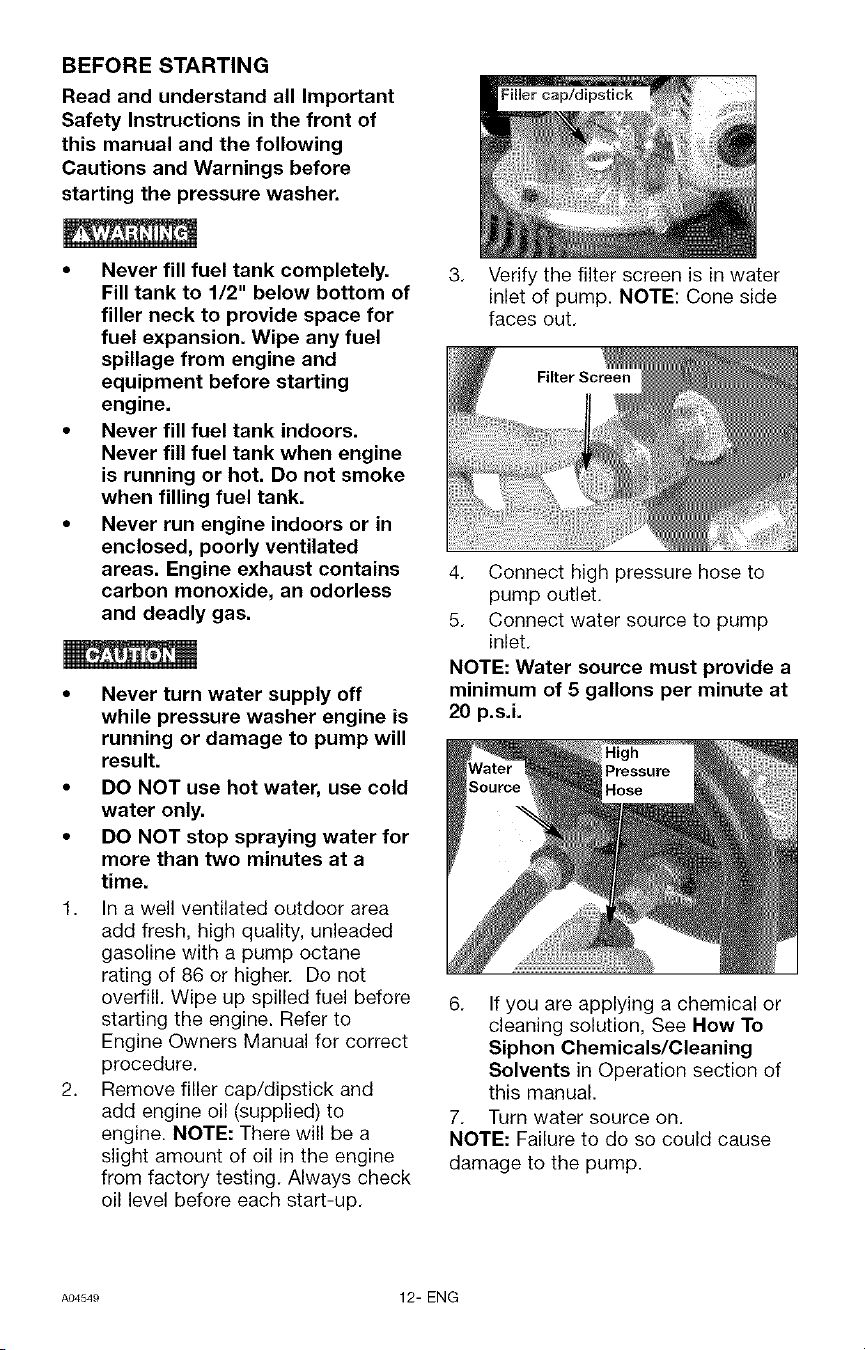
2. Remove filler cap/dipstick and
add engine oil (supplied) to
engine. NOTE: There will be a
slight amount of oil in the engine
from factory testing. Always check
oil level before each start-up.
Filler cap/dipstick
3. Verify the filter screen is in water
inlet of pump. NOTE: Cone side
faces out.
4. Connect high pressure hose to
pump outlet.
5. Connect water source to pump
inlet.
NOTE: Water source must provide a
minimum of 5 gallons per minute at
20 p.s.i.
6. If you are applying a chemical or
cleaning solution, See How To
Siphon Chemicals/Cleaning
Solvents in Operation section of
this manual.
7. Turn water source on.
NOTE: Failure to do so could cause
damage to the pump.
AO454e 12- ENG
8.
9.
Turn fuel valve to the ON position,
1/4 turn counterclockwise.
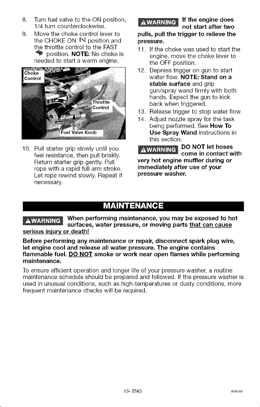
Move the choke control lever to
the CHOKE ON N position and
the throttle control to the FAST
position. NOTE: No choke is
needed to start a warm engine.
10. Pull starter grip slowly until you
feel resistance, then pull briskly.
Return starter grip gently. Pull
rope with a rapid full arm stroke.
Let rope rewind slowly. Repeat if
necessary.
If the engine does
not start after two
pulls, pull the trigger to relieve the
pressure.
11. If the choke was used to start the
engine, move the choke lever to
the OFF position.
12. Depress trigger on gun to start
water flow. NOTE: Stand on a
stable surface and grip
gun/spray wand firmly with both
hands. Expect the gun to kick
back when triggered.
13. Release trigger to stop water flow.
14. Adjust nozzle spray for the task
being performed. See Now To
Use Spray Wand instructions in
this section.
DO NOT let hoses
come in contact with
very hot engine muffler during or
immediately after use of your
pressure washer.
When performing maintenance, you may be exposed to hot
surfaces, water pressure, or moving parts that can cause
serious injury or death!
Before performing any maintenance or repair, disconnect spark plug wire,
let engine cool and release all water pressure. The engine contains
flammable fuel. DO NOT smoke or work near open flames while performing
maintenance.
To ensure efficient operation and longer life of your pressure washer, a routine
maintenance schedule should be prepared and followed. If the pressure washer is
used in unusual conditions, such as high-temperatures or dusty conditions, more
frequent maintenance checks will be required.
13- ENG A04549
CUSTOMER RESPONSIBILITIES TABLE
Before
MAINTENANCE TASK each use
ENGINE
check oil level X
change oil
check air filter
clean/replace spark plug
PRESSURE WASHER
checWclean inlet screen X
check high pressure hose ×
check soap and chemical ×
hose and filter
check gun and wand for leaks ×
prepare for storage
Every 25 Every 50 Every 100
hours or hours or hours or
yearly yearly yearly
X
X
X
Prepare unit for storage if it isto remain idle for longer
than 30 days
ENGINE
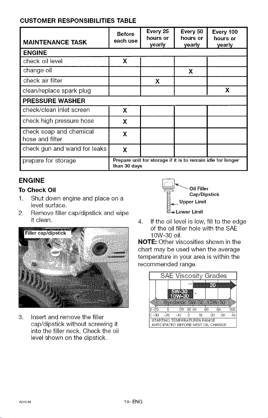
To Check Oil
1. Shut down engine and place on a
level surface.
2. Remove filler cap/dipstick and wipe
it clean.
Filler cap/dipstick
3. Insert and remove the filler
cap/dipstick without screwing it
into the filler neck. Check the oil
level shown on the dipstick.
___o_wPi Oil Filler
Cap/Dipstick
4. If the oil level is low, fill to the edge
of the oil filler hole with the SAE
10W-30 oil.
NOTE: Other viscosities shown in the
chart may be used when the average
temperature in your area is within the
recommended range.
SAE Viscosity Grades
F-2o o to 321o _o _o 1oo
-30 -20 -10 0 10 20 30 40
STARTING TEMPERATURES RANGE
ANTICIPATED BEFORE NEXT OIL CHANGE
A04549 14- ENG
To Change Oil
Drain the engine oil when the engine is
warm. Warm oil drains quickly and
completely.
1. Turn the fuel valve to the OFF
position, 1/4 turn clockwise.
2. Place a suitable container next to
the engine to catch the used oil.
3. Remove filler cap/dipstick and
drain the oil into the container by
tipping the engine toward the oil
filler neck.
Oil Filler Neck
_L_j_. Oil Filler
_ Cap/Dipstick
_ Upper Limit
L_== Lower Limit
NOTE: Please dispose of used motor
oil in a manner that is compatible with
the environment. It is recommended to
take used oil in a sealed container to
your local recycling center or service
station for reclamation. Do not throw it
in the trash or pour it on the ground or
down a drain.
4. With the engine in a level position,
fill to the upper limit mark on the
dipstick with SAE 10W-30 oil.
Engine oil capacity is 0.58 quart
(.055 liter). NOTE: Other
viscosities shown in the chart in
the "To Check Oil" paragraph may
be used.
5. Replace the oil filler cap/dipstick
securely.
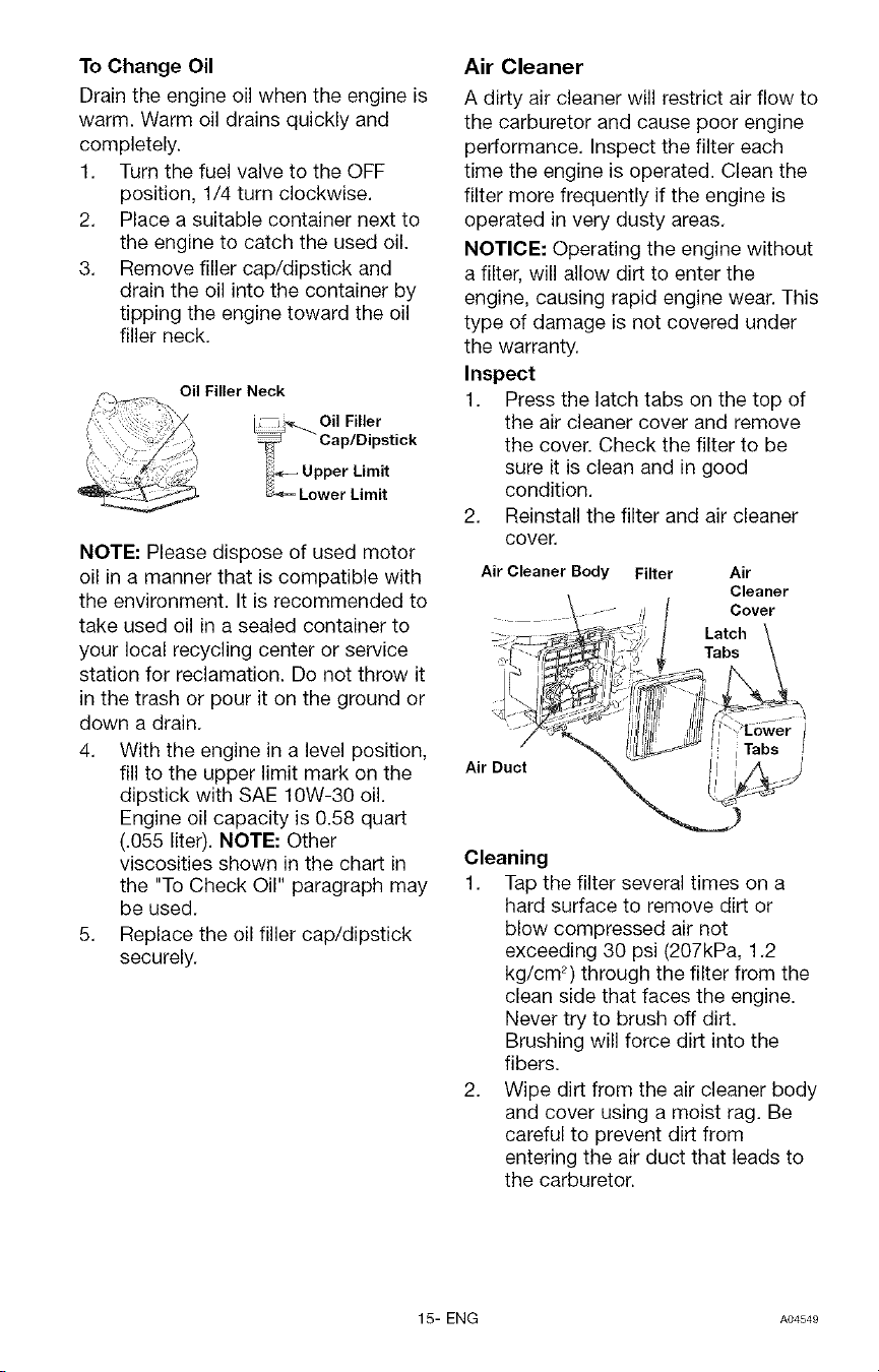
Air Cleaner
A dirty air cleaner will restrict air flow to
the carburetor and cause poor engine
performance. Inspect the filter each
time the engine is operated. Clean the
filter more frequently if the engine is
operated in very dusty areas.
NOTICE: Operating the engine without
a filter, will allow dirt to enter the
engine, causing rapid engine wear. This
type of damage is not covered under
the warranty.
Inspect
1. Press the latch tabs on the top of
the air cleaner cover and remove
the cover. Check the filter to be
sure it is clean and in good
condition.
2. Reinstall the filter and air cleaner
cover,
Air Cleaner Body Filter Air
Cleaner
Cover
Latch
Tabs
Air Duct
-=r/
Cleaning
1. Tap the filter several times on a
hard surface to remove dirt or
blow compressed air not
exceeding 30 psi (207kPa, 1.2
kg/cm 2) through the filter from the
clean side that faces the engine.
Never try to brush off dirt.
Brushing will force dirt into the
fibers.
2. Wipe dirt from the air cleaner body
and cover using a moist rag. Be
careful to prevent dirt from
entering the air duct that leads to
the carburetor.
15- ENG AO4S4e
Clean and Replace Spark Plug
Change the spark plug every 100 hours
of operation or once each year,
whichever comes first. This will help
your engine to start easier and run
better.
.030" (0.76 MM)
Wire Gauge
Resistor
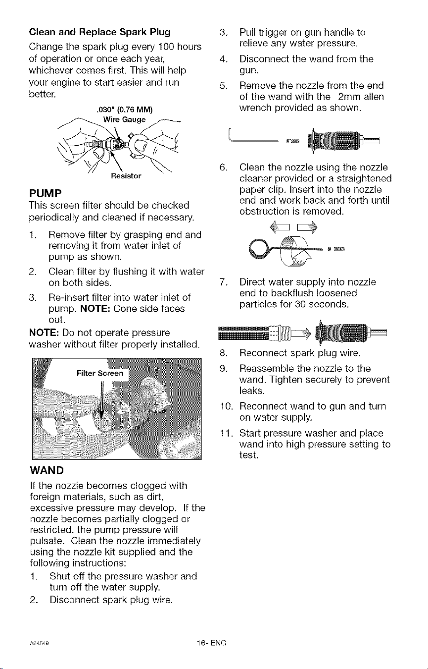
PUMP
This screen filter should be checked
periodically and cleaned if necessary.
1. Remove filter by grasping end and
removing it from water inlet of
pump as shown.
2. Clean filter by flushing it with water
on both sides.
3. Re-insert filter into water inlet of
pump. NOTE: Cone side faces
out.
NOTE: Do not operate pressure
washer without filter properly installed.
WAN D
If the nozzle becomes clogged with
foreign materials, such as dirt,
excessive pressure may develop. If the
nozzle becomes partially clogged or
restricted, the pump pressure will
pulsate. Clean the nozzle immediately
using the nozzle kit supplied and the
following instructions:
1. Shut off the pressure washer and
turn off the water supply.
2. Disconnect spark plug wire.
3. Pull trigger on gun handle to
relieve any water pressure.
4. Disconnect the wand from the
gun.
5. Remove the nozzle from the end
of the wand with the 2mm allen
wrench provided as shown.
6. Clean the nozzle using the nozzle
cleaner provided or a straightened
paper clip. Insert into the nozzle
end and work back and forth until
obstruction is removed.
7.
Direct water supply into nozzle
end to backflush loosened
particles for 30 seconds.
8. Reconnect spark plug wire.
9. Reassemble the nozzle to the
wand. Tighten securely to prevent
leaks.
10. Reconnect wand to gun and turn
on water supply.
11. Start pressure washer and place
wand into high pressure setting to
test.
A04549 16- ENG
ENGINE
IMPORTANT: It is important to prevent
gum deposits from forming in essential
fuel system parts such as the
carburetor, fuel filter, hose or tank
during storage. Also, experience
indicates that alcohol-blended fuels
(called gasohol or using ethanol or
methanol) can attract moisture which
leads to separation and formation of
acids during storage. Acidic gas can
damage the fuel system of an engine
while in storage. To avoid engine
problems, the fuel system should be
emptied before storage of 30 days or
longer. Never use engine or carburetor
cleaner products in the fuel tank or per-
manent damage may occur.
Engine Preparation
1. First add a fuel stabilizer to the
fuel tank.
2. Run pressure washer for a full 5
minutes to allow fuel stabilizer to
enter the fuel system.
While preparing the
engine make sure
water supply is turned on and
flowing to the unit. NEVER run unit
without water supply running
through pump. Failure to do so will
cause pump damage.
3. Next shut off engine and
disconnect the water supply.
4. Disconnect the spark plug wire
and remove the spark plug.
5. Add one teaspoon of oil through
the spark plug hole.
6. Place rag over spark plug hole and
pull the recoil a few times to
lubricate the combustion chamber.
7. Replace the spark plug, but do not
connect the spark plug wire.
PUMP
1. Drain all water from high pressure
hose, coil it, and store it in cradle
of the pressure washer handle.
2. Drain all water from spray gun and
spray wand by holding spray gun
in a vertical position with nozzle
end pointing down and squeezing
trigger. Store in gun/hose holder.
3. Store chemical hose, high pressure
hose, spray gun, and spray wand
so they are protected from dam-
age, such as being run over.
IThe manufacturer recommends using
a pump protector/winterizer when
storing the unit for more than 30 days
and/or when freezing temperatures are
expected. If a pump protector/winterizer
is not available, *RV antifreeze needs to
be run through the pump as outlined in
the steps below.
NOTE: Using a pump protector/winterizer
or *RV antifreeze is to provide proper
lubrication to the internal seals of the
pump regardless of temperature or
environment.
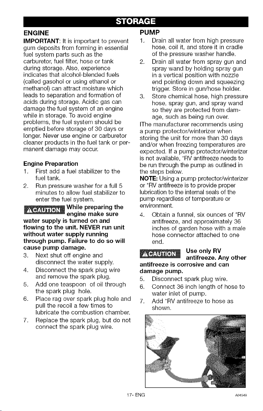
4,
Obtain a funnel, six ounces of *RV
antifreeze, and approximately 36
inches of garden hose with a male
hose connector attached to one
end.
Use only RV
antifreeze. Any other
antifreeze is corrosive and can
damage pump.
5, Disconnect spark plug wire,
6, Connect 36 inch length of hose to
water inlet of pump.
7. Add *RV antifreeze to hose as
shown.
17- ENG A04549
8. Pull engine starter rope slowly
several times until antifreeze
comes out of high pressure hose
connection of pump.
9. Remove short hose from water
inlet of pump.
10. Reconnect spark plug wire.
*Windshield washer fluid may also be
used
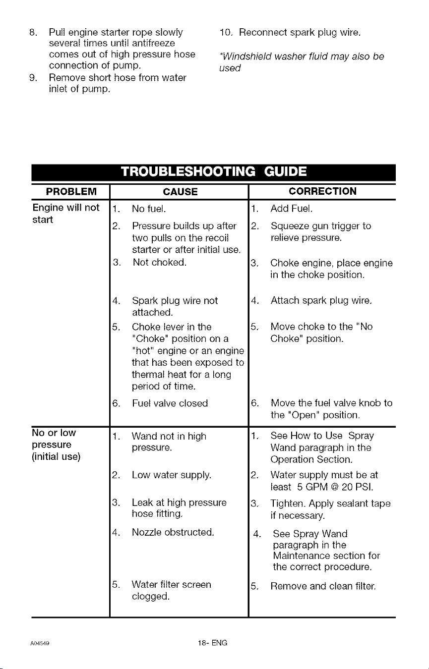
PROBLEM
Engine will not
start
No or low
pressure
(initial use)
1.
2.
3.
4.
5.
CAUSE
No fuel.
Pressure builds up after
two pulls on the recoil
starter or after initial use.
Not choked.
Spark plug wire not
attached.
Choke lever in the
"Choke" position on a
"hot" engine or an engine
that has been exposed to
thermal heat for a long
CORRECTION
1. Add Fuel.
2. Squeeze gun trigger to
relieve pressure.
3. Choke engine, place engine
in the choke position.
4. Attach spark plug wire.
5. Move choke to the "No
Choke" position.
period of time.
6. Fuel valve closed
1. Wand not in high
pressure.
2. Low water supply.
3. Leak at high pressure
hose fitting.
4. Nozzle obstructed.
5. Water filter screen
clogged.
6. Move the fuel valve knob to
the "Open" position.
1. See How to Use Spray
Wand paragraph in the
Operation Section.
2. Water supply must be at
least 5 GPM @ 20 PSI.
3. Tighten. Apply sealant tape
if necessary.
4. See Spray Wand
paragraph in the
Maintenance section for
the correct procedure.
5. Remove and clean filter.
A04549 18- ENG
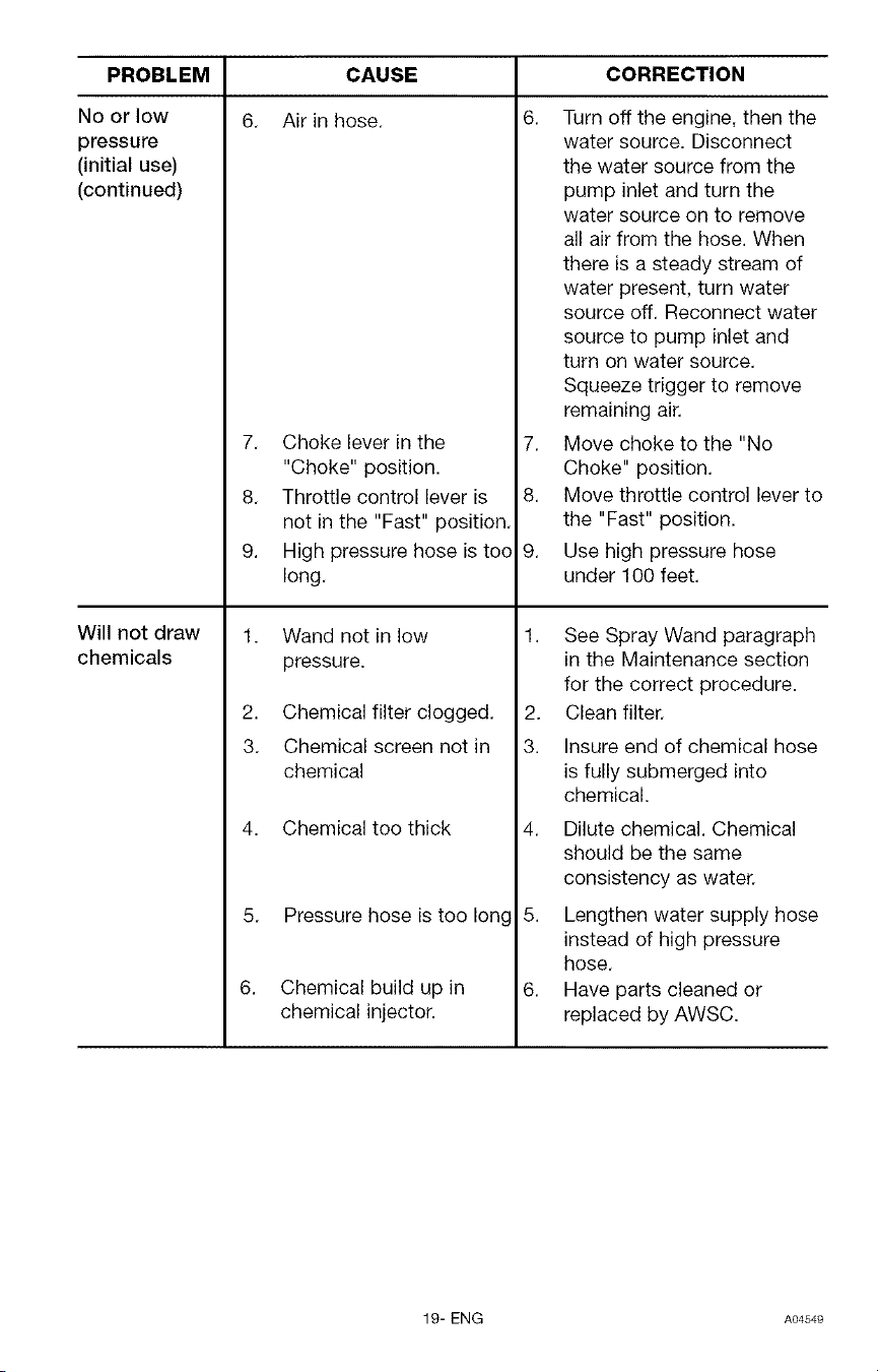
PROBLEM CORRECTION
6.No or low
pressure
(initial use)
(continued)
Will not draw
chemicals
6.
CAUSE
Air in hose.
7. Choke lever in the
"Choke" position.
8. Throttle control lever is
not in the "Fast" position.
9. High pressure hose is too
long.
1. Wand not in low
pressure.
2. Chemical filter clogged.
3. Chemical screen not in
chemical
4. Chemical too thick
5. Pressure hose is too long
Chemical build up in
chemical injector.
7.
8.
9.
Turn off the engine, then the
water source. Disconnect
the water source from the
pump inlet and turn the
water source on to remove
all air from the hose. When
there is a steady stream of
water present, turn water
source off. Reconnect water
source to pump inlet and
turn on water source.
Squeeze trigger to remove
remaining air.
Move choke to the "No
Choke" position.
Move throttle control lever to
the "Fast" position.
Use high pressure hose
under 100 feet.
1. See Spray Wand paragraph
in the Maintenance section
for the correct procedure.
2. Clean filter.
3. Insure end of chemical hose
is fully submerged into
chemical.
4. Dilute chemical. Chemical
should be the same
consistency as water.
5. Lengthen water supply hose
instead of high pressure
hose.
6. Have parts cleaned or
replaced by AWSC.
19- ENG A04549
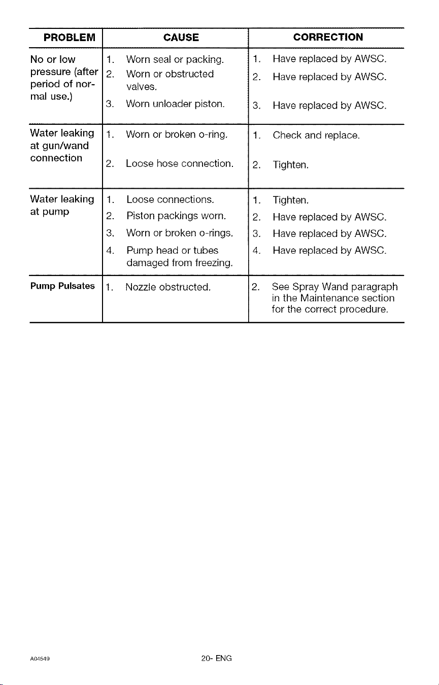
PROBLEM CAUSE
No or low
pressure (after
period of nor-
mal use.)
Water leaking
at gun/wand
connection
Water leaking
at pump
Pump Pulsates
1. Worn seal or packing.
2. Worn or obstructed
valves.
3. Worn unloader piston.
1. Worn or broken o-ring.
2. Loose hose connection.
1. Loose connections.
2. Piston packings worn.
3. Worn or broken o-rings.
4. Pump head or tubes
damaged from freezing.
1. Nozzle obstructed.
CORRECTION
1. Have replaced by AWSC.
2. Have replaced by AWSC.
3. Have replaced byAWSC.
1. Check and replace.
2. Tighten.
1. Tighten.
2. Have replaced by AWSC.
3. Have replaced by AWSC.
4. Have replaced by AWSC.
See Spray Wand paragraph
in the Maintenance section
for the correct procedure.
A04S4e 20- ENG
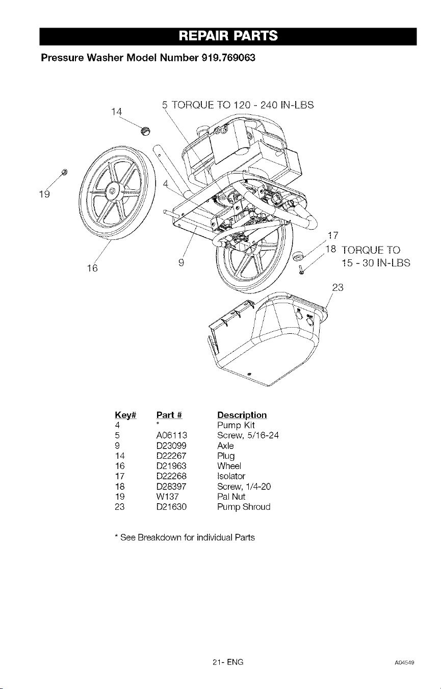
I:! _l_/:II:! I_:I :i _.'1
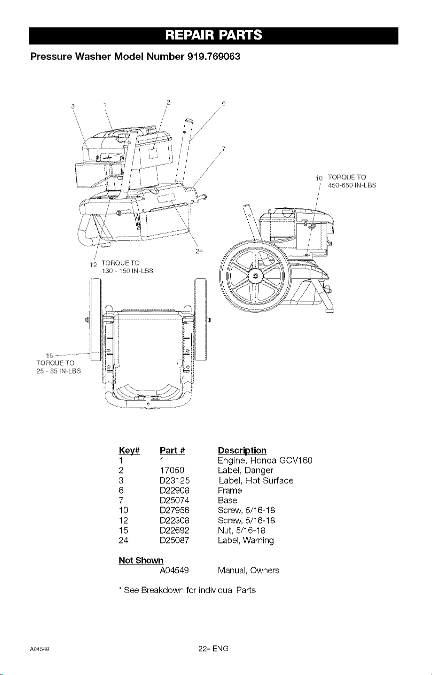
Pressure Washer Model Number 919.769063
14 5TORQUE TO 120 - 240 IN-LBS
-%
19
16
17
TORQUE TO
15 - 30 IN-LBS
23
Part # Description
4 Pump Kit
5 A06113 Screw, 5/16-24
9 D23099 Axle
14 D22267 Plug
16 D21963 Wheel
17 D22268 Isolator
18 D28397 Screw, 1/4-20
19 W137 Pal Nut
23 D21630 Pump Shroud
* See Breakdown for individual Parts
21- ENG A04549
I:I :1:7_.II:I 1:7_._:_i__]
Pressure Washer Model Number 919.769063
6
/
10 TORQUE TO
450 650 iN LBS
12 TORQUE TO
15 "
TORQUE TO
25 35 iN LBS
24
130 150H LBS
il,
Part # Description
1 Engine, Honda GCV160
2 17050 Label, Danger
3 D23125 Label, Hot Surface
6 D22908 Frame
7 D25074 Base
10 D27956 Screw, 5/16-18
12 D22308 Screw, 5/16-18
15 D22692 Nut, 5/16-18
24 D25087 Label, Warning
Not Shown
A04549 Manual, Owners
* See Breakdown for individual Parts
A04549 22- ENG
II'! =lq;IlI'_ I_l =_I_'_
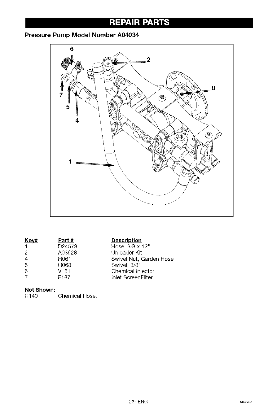
Pressure Pump Model Number A04034
6
1
2
4
5
6
7
Not Shown:
H140
Part #
D24573
A03928
H061
H068
Vl 61
F187
Chemical Hose,
Description
Hose, 3/8 x 12"
Unloader Kit
Swivel Nut, Garden Hose
Swivel, 3/8"
Chemical Injector
Inlet ScreenFilter
23- ENG A04549
;! =1__'I I;! #'-'I;tl I__]
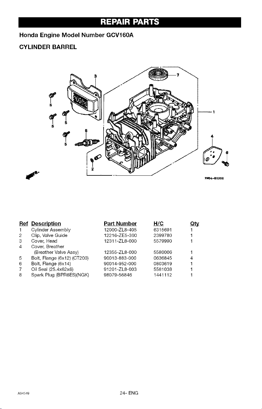
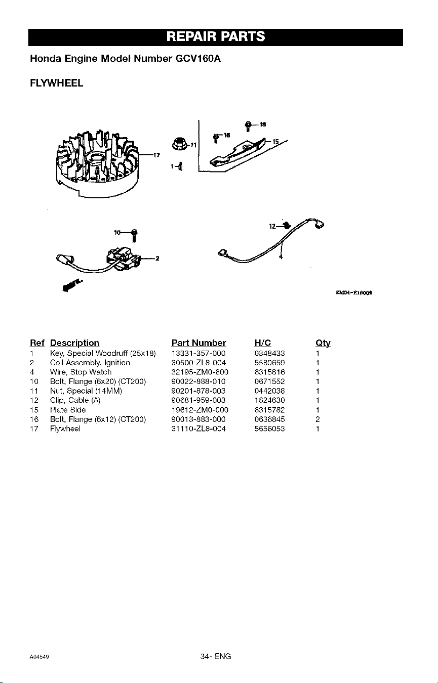
Honda Engine Model Number GCV160A
CYLINDER BARREL
2=_-B03¢0
Ref Description
1 Cylinder Assembly
2 Clip, Valve Guide
3 Cover, Head
4 Cover, Breather
(Breather Valve Assy)
5 Bolt, Flange (6x12) (CT2OO)
6 Bolt, Flange (6x14)
7 Oil Seal (25.4x62x6)
8 Spark Plug (BPR6ES)(NGK)
Part Number H/C
12000-ZL8-405 6315691
12216-ZE5-300 2399780
12311-ZL8-000 5579990
12355-ZL8-000 5580006
90013-883-000 0636845
90014-952-000 0803619
91201-ZL8-003 5581038
98079-56846 1441112
QLv
1
1
1
1
4
1
1
1
A04549 24- ENG
--!_ _:I I--!1_:I --t1__]
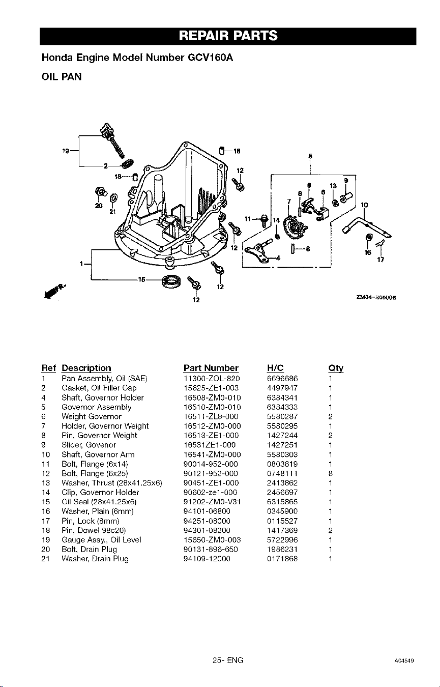
Honda Engine Model Number GCV160A
OIL PAN
12
10
_i_ _
12
Z_04-}_O_O0 B
Ref Description
1 Pan Assembly, Oil (SAE)
2 Gasket, Oil Filler Cap
4 Shaft, Governor Holder
5 Governor Assembly
6 Weight Governor
7 Holder, Governor Weight
8 Pin, Governor Weight
9 Slider, Govenor
10 Shaft, Governor Arm
11 Bolt, Flange (6xl 4)
12 Bolt, Flange (6x25)
13 Washer, Thrust (28x41.25x6)
14 Clip, Governor Holder
15 Oil Seal (28x41.25x6)
16 Washer, Plain (6mm)
17 Pin, Lock (Smm)
18 Pin, Dowel 98c20)
19 Gauge Assy., Oil Level
20 Bolt, Drain Plug
21 Washer, Drain Plug
Part Number
11300-ZOL-820
15625-ZE1-003
16508-ZMO-010
16510-ZMO-010
16511-ZL8-OOO
16512-ZMO-OOO
16513-ZE1-000
16531ZE1-000
16541-ZMO-OOO
90014-952-000
90121-952-000
90451-ZE1-000
9O6O2-zel-OOO
91202-ZMO-V31
94101-06800
94251-08000
94301-08200
15650-ZMO-OO3
90131-896-650
94109-12000
H/C
6696686
4497947
6384341
6384333
5580287
5580295
1427244
1427251
5580303
0803619
0748111
2413862
2456697
6315865
0345900
0115527
1417369
5722996
1986231
0171868
Qtv
1
1
1
1
2
1
2
1
1
1
8
1
1
1
1
1
2
1
1
1
25- ENG A04549
I:! _l_:I I:! I_/:I :i _.']
Honda Engine Model Number GCV160A
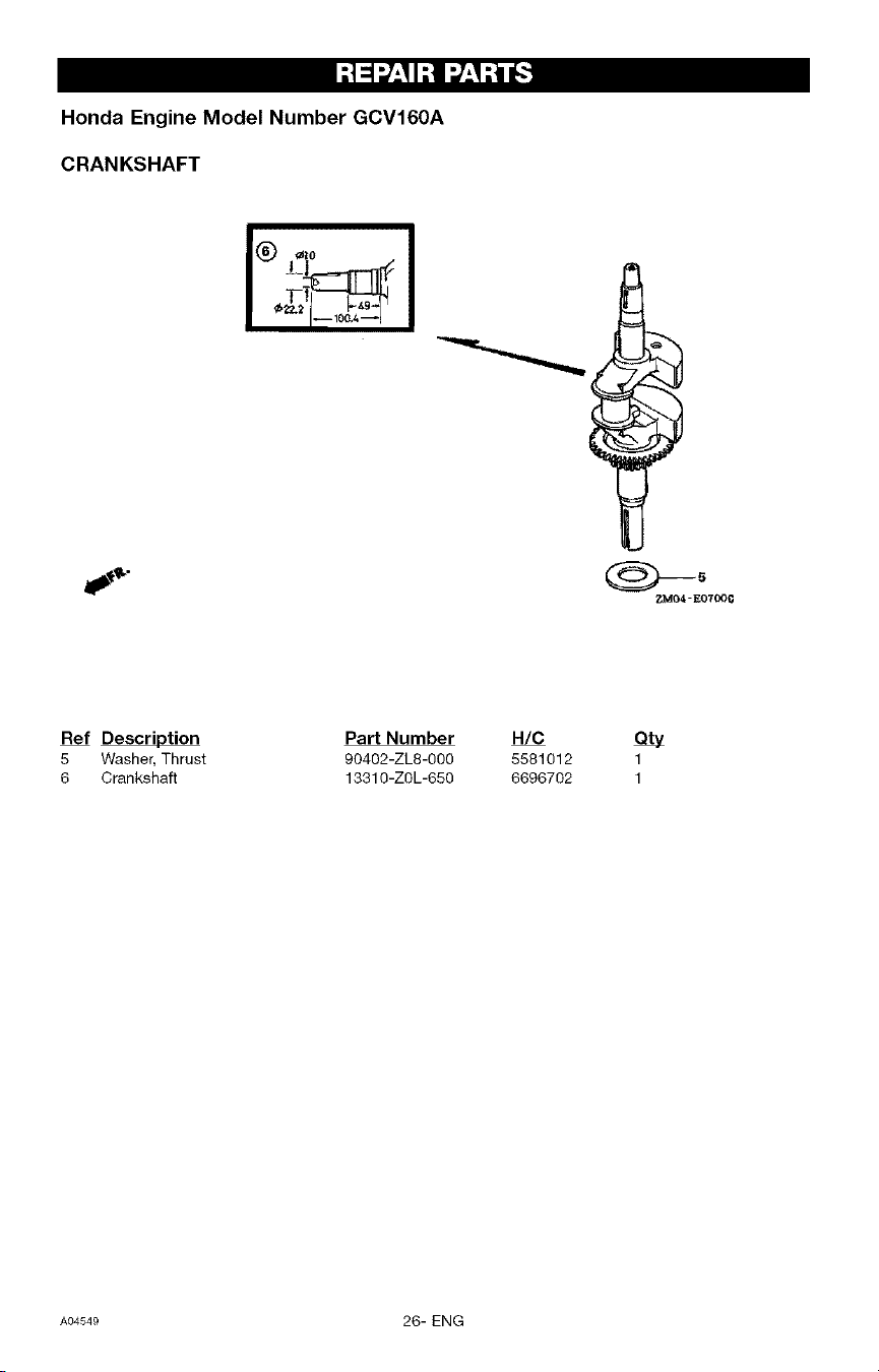
CRANKSHAFT
I® _i°
I i__10_._:_i
Ref Description Part Number
5 Washer, Thrust 9O4O2-ZL8-OOO
6 Crankshaft 13310-ZOL-650
H/C
5581012
6696702
ety
1
1
A04549 26- ENG
I -'!_ :,/_'II-'!1__'I-'tl J-]
Honda Engine Model Number GCV160A
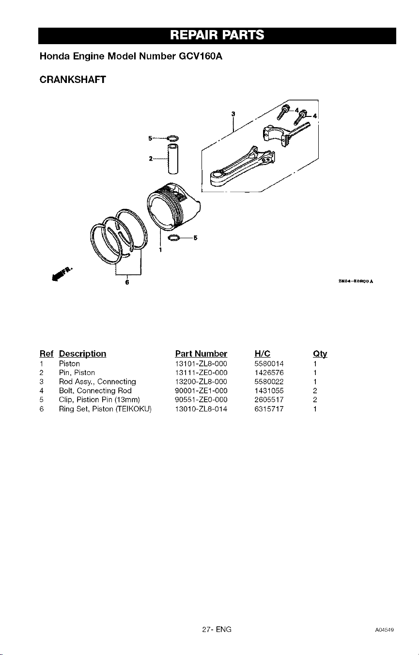
CRANKSHAFT
Ref Description Part Number H/C
1 Piston 13101-ZL8-060 5580614
2 Pin, Piston 13111-ZE0-060 1426576
3 Rod Assy., Connecting 13200-ZL8-000 5580022
4 Bolt, Connecting Rod 90O01-ZE1-0O0 1431055
5 Clip, Pistion Pin (13mm) 90551-ZE0-000 2605517
6 Ring Set, Piston (TEIKOKU) 13010-ZL8-014 6315717
1
1
1
2
2
1
27- ENG AO4549
I:! =l;/:I I:! I_:I :i _.']
Honda Engine Model Number GCV160A
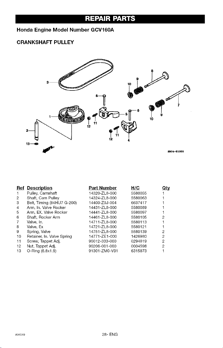
CRANKSHAFT PULLEY
13---_D
12
Ref Description
1 Pulley, Camshaft
2 Shaft, Cam Pulley
3 Belt, Timing (84HU7 G-2O0)
4 Arm, In. Valve Rocker
5 Arm, EX. Valve Rocker
6 Shaft, Rocker Arm
7 Valve, In.
8 Valve, Ex
9 Spring, Valve
10 Retainer, In. Valve Spring
11 Screw, Tappet Adj.
12 Nut, Tappet Adj.
13 O-Ring (6.8xl.9)
Part Number
14320-ZL8-000
14324-ZL8-000
14400-ZOJ-OO4
14431-ZL8-000
14441-ZL8-000
14461-ZL8-000
14711-ZL8-000
14721-ZL8-000
14751-ZL8-000
14771-ZE1-000
90012-333-000
90206-001-000
91301-ZMO-V31
H/C
5580055
5580063
6637417
5580089
5580097
5580105
5580113
5580121
5580139
1426980
0294819
0004598
6315873
Qty
1
1
1
1
1
2
1
1
2
2
2
2
1
A04549 28- ENG
I;I =1:7_.II;I 1:7_.I;i ,_.']
Honda Engine Model Number GCV160A
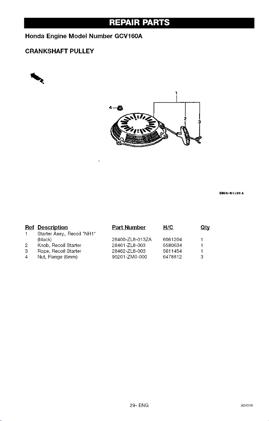
CRANKSHAFT PULLEY
1
T
2
3
Ref Description
1 Starter Assy., Recoil *NHI*
(black)
2 Knob, Recoil Starter
3 Rope, Recoil Starter
4 Nut, Flange (6rnm)
Part Number H/C
28400-ZL8-013ZA 6061204
28461-ZL8-003 5580634
28462-ZL8-003 5611454
9O201-ZM0-0O0 6478812
ety
1
1
1
3
29- ENG A04549
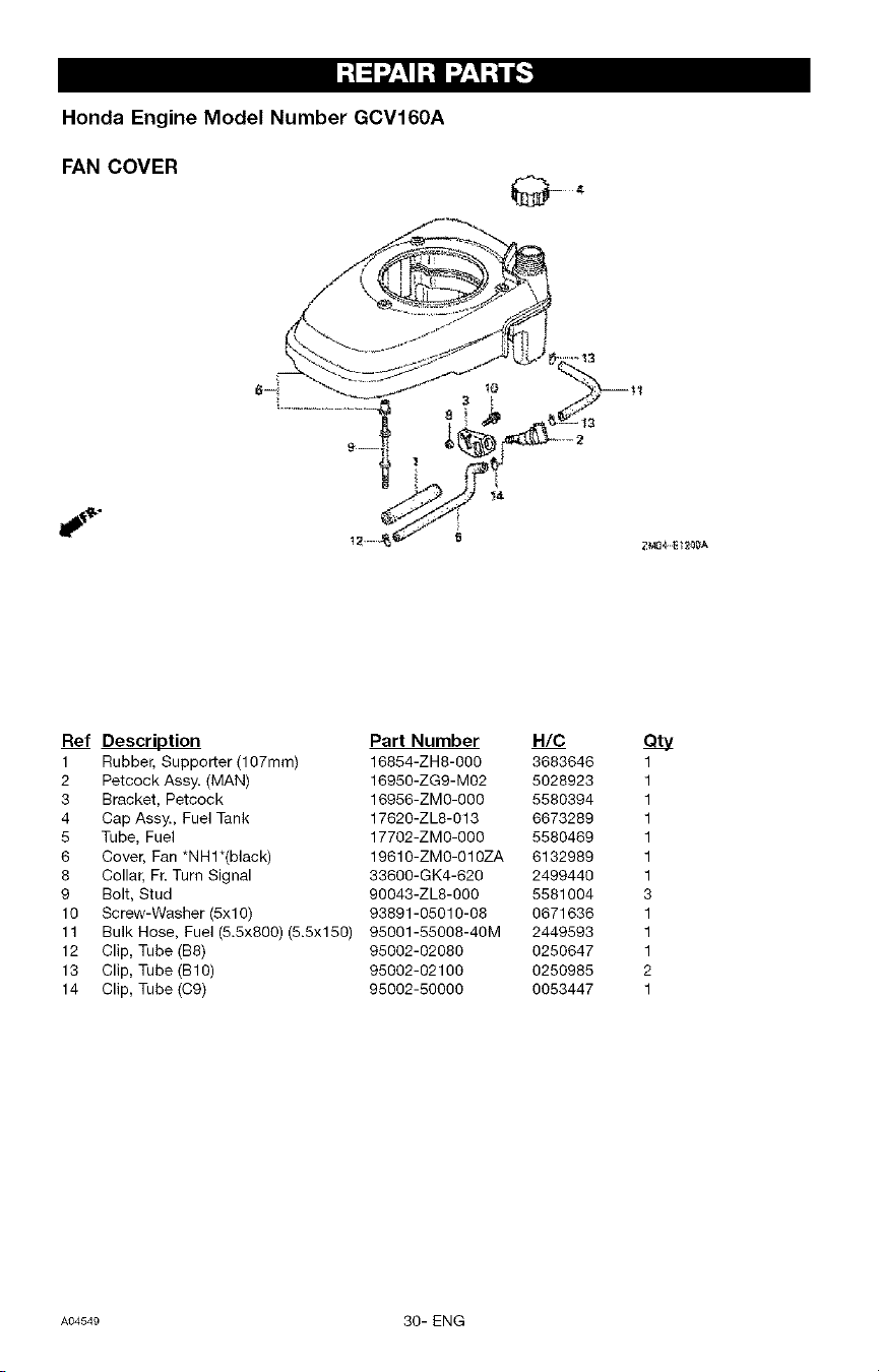
I;I _1:7__I;I 1:7__;i __]
Honda Engine Model Number GCV160A
FAN COVER
Ref Description
1 Rubber, Supporter (1O7mm)
2 Petcock Assy. (MAN)
3 Bracket, Petcock
4 Cap Assy., Fuel Tank
5 Tube, Fuel
6 Cover, Fan *NHl*(black)
8 Collar, Ft. Turn Signal
9 Bolt, Stud
10 Screw-Washer (5xl O)
11 Bulk Hose, Fuel (5.5x800) (5.5x150)
12 Clip, Tube (B8)
13 Clip, Tube (B1O)
14 Clip, Tube (C9)
Part Number H/C
16854-ZH8-000 3683646 1
16950-ZGg-MO2 5028923 1
16956-ZMO-OOO 5580394 1
17620-ZL8-013 6673289 1
17702-ZMO-O00 5580469 1
19610-ZMO-O1OZA 6132989 1
33600-GK4-620 2499440 1
90043-ZL8-OOO 5581004 3
93891-05010-08 0671636 1
95001-55008-40M 2449593 1
95002-02080 0250647 1
95002-02100 0250985 2
95002-50000 0053447 1
A04549 30- ENG
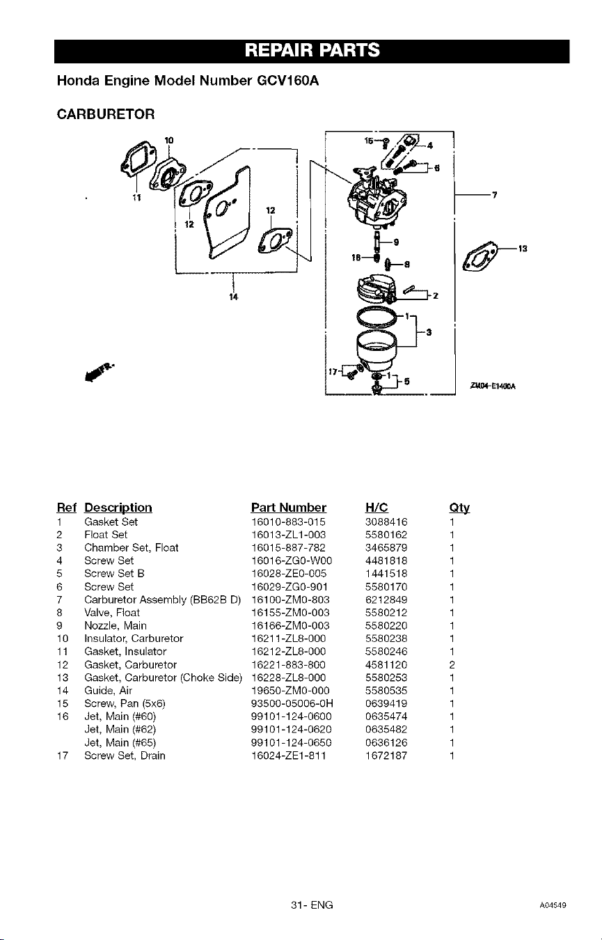
-'!_ __'I I-'!1r,/_'1-'tl 6_
Honda Engine Model Number GCV160A
CARBURETOR
'
!
Ref Description
1 Gasket Set
2 Float Set
3 Chamber Set, Float
4 Screw Set
5 Screw Set B
6 Screw Set
7 Carburetor Assembly (BB62B D)
8 Valve, Float
9 Nozzle, Main
10 Insulator, Carburetor
11 Gasket, Insulator
12 Gasket, Carburetor
13 Gasket, Carburetor (Choke Side)
14 Guide, Air
15 Screw, Pan (5x6)
16 Jet, Main (#60)
Jet, Main (#62)
Jet, Main (#65)
17 Screw Set, Drain
Part Number H/C Qty
16010-883-015 3088416 1
16013-ZL1-003 5580162 1
16015-887-782 3465879 1
16016-ZG0-W00 4481818 1
16028-ZE0-005 1441518 1
16029-ZG0-901 5580170 1
16100-ZM0-803 6212849 1
16155-ZM0-003 5580212 1
16166-ZM0-003 5580220 1
16211-ZL8-000 5580238 1
16212-ZL8-000 5580246 1
16221-883-800 4581120 2
16228-ZL8-000 5580253 1
19650-ZM0-000 5580535 1
93500-05006-0H 0639419 1
99101-124-0600 0635474 1
99101-124-0620 0635482 1
99101-124-0650 0636126 1
16024-ZE1-811 1672187 1
31- ENG AO4549
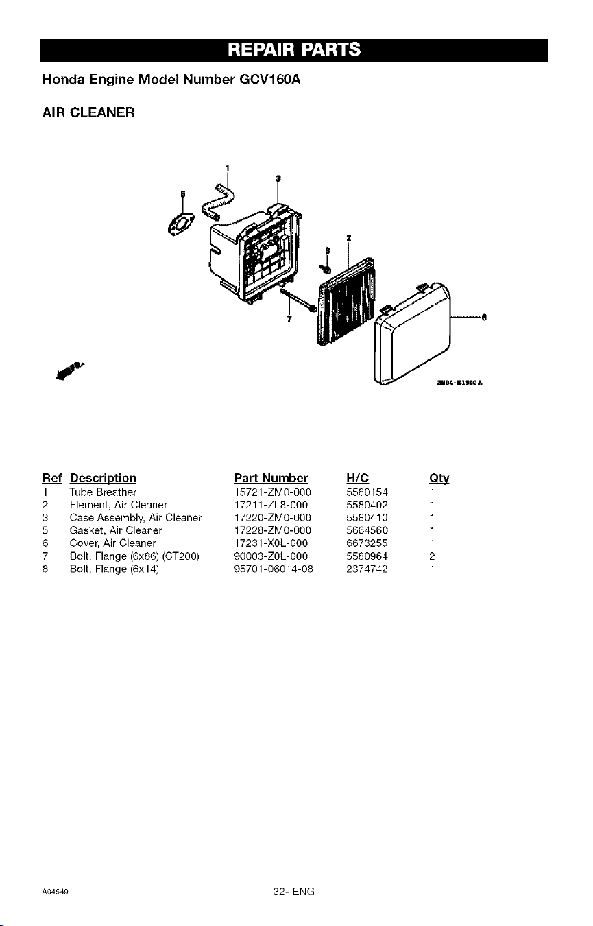
Honda Engine Model Number GCV160A
AIR CLEANER
Ref Description Part Number
1 Tube Breather 15721-ZM0-000
2 Element, Air Cleaner 17211-ZL8-000
3 Case Assembly, Air Cleaner 17220-ZM0-000
5 Gasket, Air Cleaner 17228-ZM0-000
6 Cover, Air Cleaner 17231 -X0L-000
7 Bolt, Flange (6x86) (CT200) 90003-Z0L-000
8 Bolt, Flange (6x14) 95701-06014-08
H/C
5580154
5580402
5580410
5664560
6673255
5580964
2374742
ety
1
1
1
1
1
2
1
A04549 32- ENG
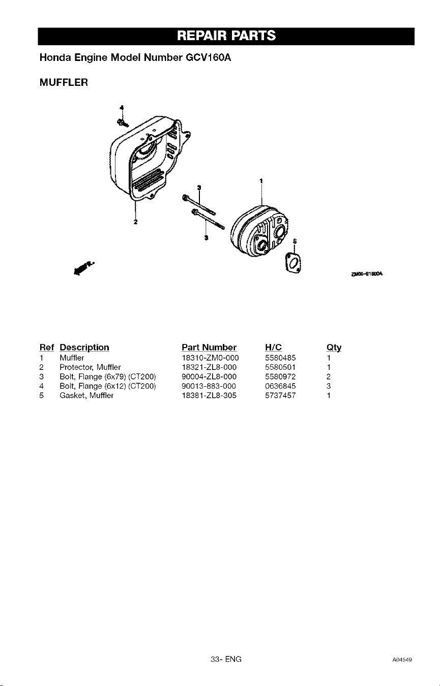
I-'!=1__,II:1 I__'I-'__
Honda Engine Model Number GCV160A
MUFFLER
4
f
Ref Description
1 Muffler
2 Protector, Muffler
3 Bolt, Flange (6x79) (CT200)
4 Bolt, Flange (6x12) (CT200)
5 Gasket, Muffler
Part Number
18310-ZMO-O00
18321-ZL8-000
90004-ZL8-000
90013-883-000
18381-ZL8-305
H/C
5580485
5580501
5580972
0636845
5737457
ety
1
1
2
3
1
33- ENG A04549
I:! _l_/:I I:! I_:I :i _.'_
Honda Engine Model Number GCV160A
FLYWHEEL
I _p-lu
Ref Description Part Number
1 Key,Special Woodruff (25x18) 13331-357-000
2 Coil Assembly, Ignition
4 Wire, Stop Watch
10 Bolt, Flange (6x20) (CT200)
11 Nut, Special (14MM)
12 Clip, Cable (A)
15 Plate Side
16 Bolt, Flange (6x12)(CT200)
17 Flywheel
H/C
0348433 1
30500-ZL8-004 5580659 1
32195-ZM0-800 6315816 1
90022-888-010 0671552 1
90201-878-003 0442038 1
90681-959-003 1824630 1
19612-ZM0-000 6315782 1
90013-883-000 0636845 2
31110-ZL8-004 5656053 1
A04549 34- ENG
I:!_1__,_I:11__,_:i _
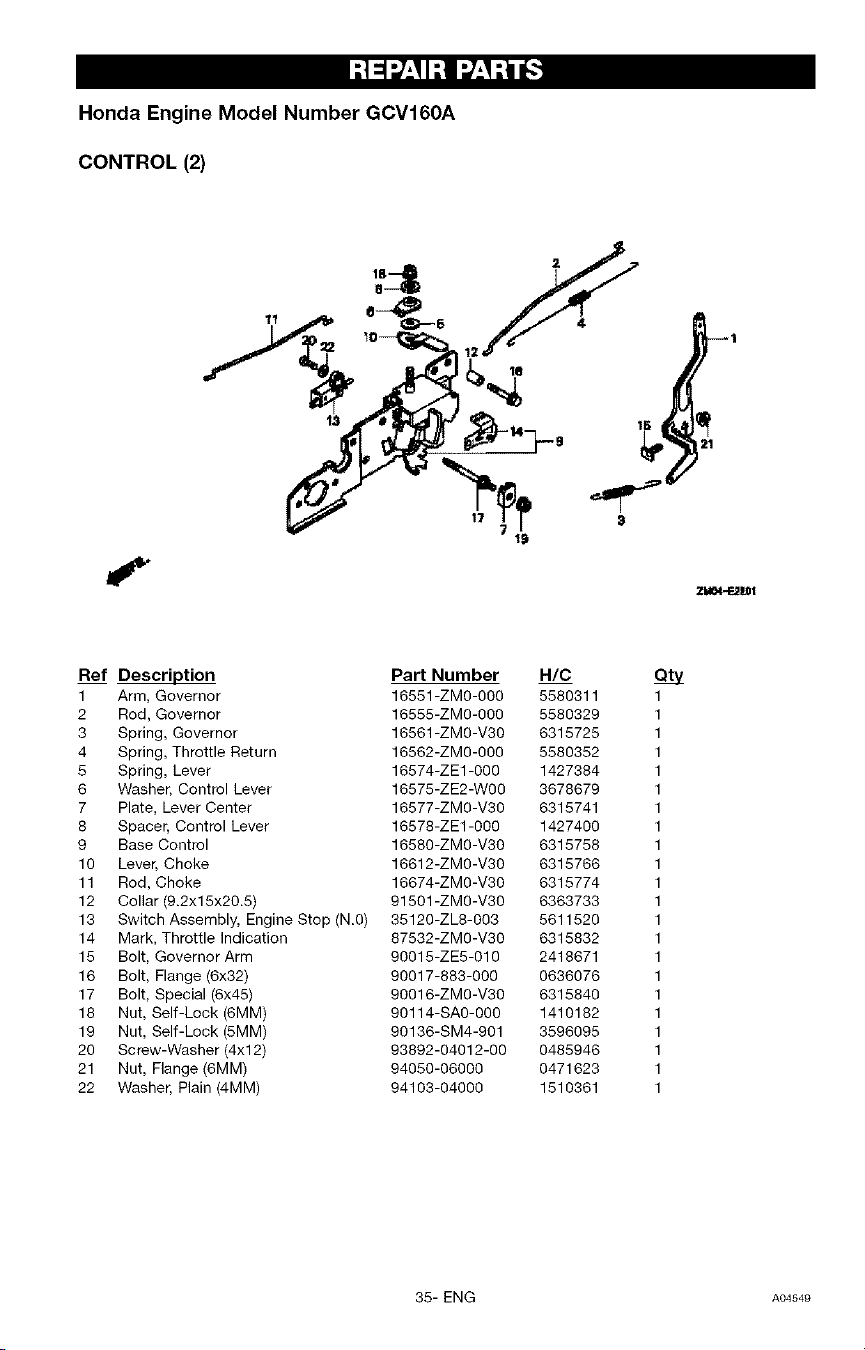
Honda Engine Model Number GCV160A
CONTROL (2)
19
z_t
Ref Description Part Number H/C
1 Arm, Governor 16551-ZM0-000 5580311 1
2 Rod, Governor 16555-ZMO-OOO 5580329 1
3 Spring, Governor 16561-ZMO-V30 6315725 1
4 Spring, Throttle Return 16562-ZMO-OOO 5580352 1
5 Spring, Lever 16574-ZE1-000 1427384 1
6 Washer, Control Lever 16575-ZE2-WOO 3678679 1
7 Plate, Lever Center 16577-ZMO-V30 6315741 1
8 Spacer, Control Lever 16578-ZE1-000 1427400 1
9 Base Control 16580-ZMO-V30 6315758 1
10 Lever, Choke 16612-ZMO-V30 6315766 1
11 Rod, Choke 16674-ZMO-V30 6315774 1
12 Collar (9.2xl 5x20.5) 91501 -ZMO-V3O 6363733 1
13 Switch Assembly, Engine Stop (N.O) 35120-ZL8-003 5611520 1
14 Mark, Throttle Indication 87532-ZMO-V30 6315832 1
15 Bolt, Governor Arm 90015-ZE5-010 2418671 1
16 Bolt, Flange (6x32) 90017-883-000 0636076 1
17 Bolt, Special (6x45) 90016-ZMO-V30 6315840 1
18 Nut, Self-Lock (6MM) 90114-SAO-OOO 1410182 1
19 Nut, Self-Lock (5MM) 90136-SM4-901 3596095 1
20 Screw-Washer (4xl 2) 93892-04012-00 0485946 1
21 Nut, Flange (6MM) 94050-06000 0471623 1
22 Washer, Plain (4MM) 94103-04000 1510361 1
35- ENG A04549
I;I =I_7_,_I;I I _7_,_;_tt_'.]
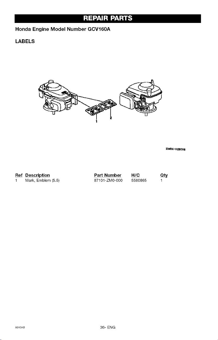
Honda Engine Model Number GCV160A
LABELS
Ref Description
1 Mark, Emblem (5.5)
Part Number H/C Qty
87101-ZMO-O00 5580865 1
A0454e 36- ENG
rnq_'_-tW_'II"] = E_o__i nl=1_II,,_o_'_
GARANTIA ................................................. 37
GRAFICO DE ESPECIFICACIONES ............................. 38
PAUTAS DE SEGURIDAD - DEFINICIONES ...................... 38
INSTRUCCIONES IMPORTANTES DE SEGURIDAD ............. 38-42
CONTENIDO DE LA CAJA .................................... 42
ENSAMBLAJE .............................................. 43
OPERACION ............................................. 44-48
MANTENIMIENTO ........................................ 48-51
ALMACENAJE ........................................... 52-53
GU|A PARA DIAGNOSTICO DE PROBLEMAS ................. 53-55
PIEZAS DE REPARACION .................................. 21-36
COMO SOLICITAR PIEZAS DE REPARACION ...... Cubierta de atr_s
GARANT|A LIMITADA DE UN AI_IO PARA
LAVADORAS CRAFTSMAN DE ALTA PRESION
Por un a_o a par_ir de la fecha de compra, y siernpre que esta Lavadora Craftsman de Alta
Presidn se mantenga y opere de acuerdo alas instrucciones en el Manual del Propietario,
Sears repararA cualquier defecto de material o fabricacidn sin costo alguno.
Si esta lavadora se usa para prop6sitos comerciales o de alquiler, la garantia s61o serA
aplicable pot 90 dfas a par[ir de la fecha de compra.
GARANT[A LIMITADA DE DOS AI_IOS DEL MOTOR CRAFTSMAN
Por dos a_os a partir de la fecha de compra, y siempre que este motor Craftsman se mantenga
y opere de acuerdo alas instrucciones en el Manual del Propietario, Sears repararA cualquier
defecto de material o fabricacidn sin costo alguno.
Si el motor Craftsman se usa para prop6sitos comerciales o de alquiler, la garantia s61oserA
aplicable pot 90 dias a partir de la fecha de compra. Esta garantfa no cubre piezas sujetas a
desgaste tales como bujfas y filtros de aire, los cuales se gastan con el uso normal.
La garantfa no cubre las reparaciones que se hagan necesarias debido al mal uso o
negligencia de pare del operador, incluyendo da_os causados por no suministrarle agua a la
bomba o no mantener el equipo de acuerdo alas instrucciones contenidas en este manual.
SE PUEDE OBTENER SERVlCIO POR GARANTiA Sl SE LLEVA LA LAVADORA DE ALTA
PRESlON AL CENTRO/DEPARTAMENTO DE SERVICIO DE GARANTiA DE SEARS M,g,S
CERCANO EN CUALQUIER LUGAR DE ESTADOS UNIDOS. Esta garantfa le otorga ciertos
derechos legales especfficos y usted tambi_n podrfa tener otros derechos que varfan de un
estado a otro.
Sears, Roebuck and Co., D/817 WA, Hoffman Estates, IL 60179
37- SP AO4549
[_*']_;]_][_o] I"1:=1[_.__o,][o]_]_..']
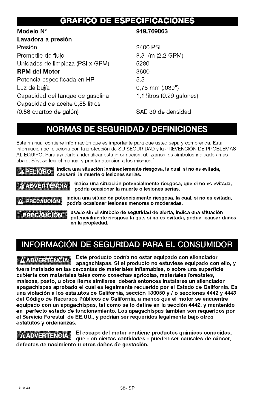
Modelo N°
Lavadora a presi6n
Presi6n
Promedio de flujo
Unidades de limpieza (PSI x GPM)
RPM del Motor
Potencia especificada en HP
Luz de bujfa
Capacidad del tanque de gasolina
Capacidad de aceite 0,55 litros
(0.58 cuartos de gal6n)
919.769063
2400 PSI
8,3 I/m (2.2 GPM)
5280
3600
5.5
0,76 mm (.030")
1,1 litros (0.29 galones)
SAE 30 de densidad
Este manual contiene informacion que es importante para que usted sepa y comprenda. Esta
informacion se relaciona con la proteccion de SU SEGURIDAD y la PREVENCION DE PROBLEMAS
AL EQUIPO. Para ayudarle a identificar esta informacion, utilizamos los simbolos indicados mas
abajo. Sirvase leer el manual y prestar atencion a los mismos."
indica una situaci6n inminentemente riesgosa, la cual, si no es evitada,
causara la muerte o lesiones serias.
indica una situaci6n potencialmente riesgosa, que si no es evitada,
podria ocasionar la muerte o lesiones serias.
indica una situaci6n potencialmente riesgosa, la cual, si no es evitada,
podda ocasionar lesiones menores o moderadas.
usado sin el sirnbolo de seguridad de alerta, indica una situaci6n
potencialmente riesgosa la que, si no es evitada, podria causar dahos
en la propiedad.
,,_.,, Este producto podria no estar equipado con silenciador
apagachispas. Si el producto no estuviese equipado con ello, y
fuera instalado en las cercanias de materiales inflamables, o sobre una superficie
cubierta con materiales tales como cosechas agricolas, materiales forestales,
malezas, pasto, u otros items similares, debera entonces instalarse un silenciador
apagachispas aprobado el cual es legalmente requerido por el Estado de California. Es
una violacibn a los estatutos de California, secci6n 130050 y / o secciones 4442 y 4443
del Cbdigo de Recursos P_blicos de California, a menos que el motor se encuentre
equipado con un apagachispas, tal como se Io define en la seccibn 4442, y mantenido
en perfecto estado de funcionamiento. Los apagachispas tambi_n son requeridos por
el Servicio Forestal de EE.UU., y podrian ser requeridos legalmente bajo otros
estatutos y ordenanzas.
,,=o, El escape del motor contiene productos quimicos conocidos,
que - en ciertas cantidades - pueden ser causales de cancer,
defectos de nacimiento u otros da_os de gestaci6n.
A04549 38- SP
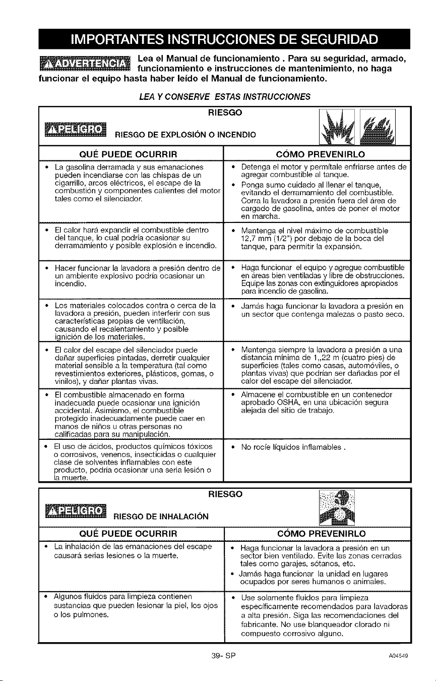
Lea el Manual de funcionamiento. Para su seguridad, armado,
funcionamiento e instrucciones de mantenimiento, no haga
funcionar el equipo hasta haber le|do el Manual de funcionamiento.
LEA Y CONSERVE ESTAS INSTRUCCIONES
RIESGO
RIESGO DE EXPLOSION 0 INCENDIO
QU# PUEDE OCURRIR
• La gasolina derramada y sus emanaciones
pueden ineendiarse con las chispas de un
cigarrillo, amos electricos, el escape de la
combusti6n y componentes calientes del motor
tales como el silenciador.
• El calor harA expandir el combustible dentro
del tanque, Io cual podria ocasionar su
derramamiento y posible explosi6n e incendio.
• Haeer funcionar la lavadora a presion dentro de
un ambiente explosivo podrfa ocasionar un
incendio.
• Los materiales colocados contra o cerca de la
lavadora a presion, pueden interferir con sus
caracterfstieas propias de ventilaeion,
causando el recalentamiento y posible
ignici6n de los materiales.
• El calor del escape del silenciador puede
daSar superficies pintadas, derretir cualquier
material sensible a la temperatura (tal como
revestimientos exteriores, plasticos, gomas, o
vinilos), y daSar plantas vivas.
• El combustible almacenado en forma
inadecuada puede ocasionar una ignicion
accidental. Asimismo, el combustible
protegido inadeeuadamente puede caer en
manos de ni_os u otras personas no
calificadas para su manipulaci6n.
• El uso de acidos, productos quimicos toxicos
o corrosivos, venenos, insecticidas o cualquier
clase de solventes inflamables con este
producto, podria ocasionar una seria lesion o
la muerte.
COMO PREVENIRLO
• Detenga el motor y permitale enfriarse antes de
agregar combustible al tanque.
• Ponga sumo cuidado al Ilenar el tanque,
evitando el derramamiento del combustible.
Corra la lavadora a presion fuera del Area de
cargado de gasolina, antes de poner el motor
ell marcha.
• Mantenga el nivel maximo de combustible
12,7 mm (1/2") por debajo de la boca del
tanque, para permitir la expansion.
Haga funcionar el equipo y agregue combustible
en Areas bien ventiladas y libre de obstrucciones.
Equipe las zonas con extinguidores apropiados
para incendio de gasolina.
• Jamas haga funcionar la lavadora a presion en
un sector que contenga malezas o pasto seco.
• Mantenga siempre la lavadora a presi6n a una
distancia minima de 1,22 m (cuatro pies) de
superficies (tales como casas, automoviles, o
plantas vivas) que podrian set daSadas por el
calor del escape del silenciador.
• Almacene el combustible en un contenedor
aprobado OSHA, en una ubicacion segura
alejada del sitio de trabajo.
• No rocfe Ifquidos inflamables.
RIESGO
RIESGO DE INHALACION
QU# PUEDE OCURRIR COMO PREVENIRLO
• La inhalacion de las emanaciones del escape • Haga funcionar la lavadora a presi6n en un
causara serias lesiones 0 la muerte, sector bien ventilado. Evite las zonas cerradas
tales como garajes, sotanos, etc.
• Jamas haga funcionar la unidad en lugares
ocupados por seres humanos 0 animales.
• Algunos fluidos para limpieza contienen • Use solamente fluidos para limpieza
sustancias que pueden lesionar la piel, los ojos especificamente recomendados para lavadoras
0 los pulmones, a alta presion. Siga las recomendaciones del
fabricante. No use blanqueador clorado ni
compuesto corrosivo alguno.
39- SP AO4549
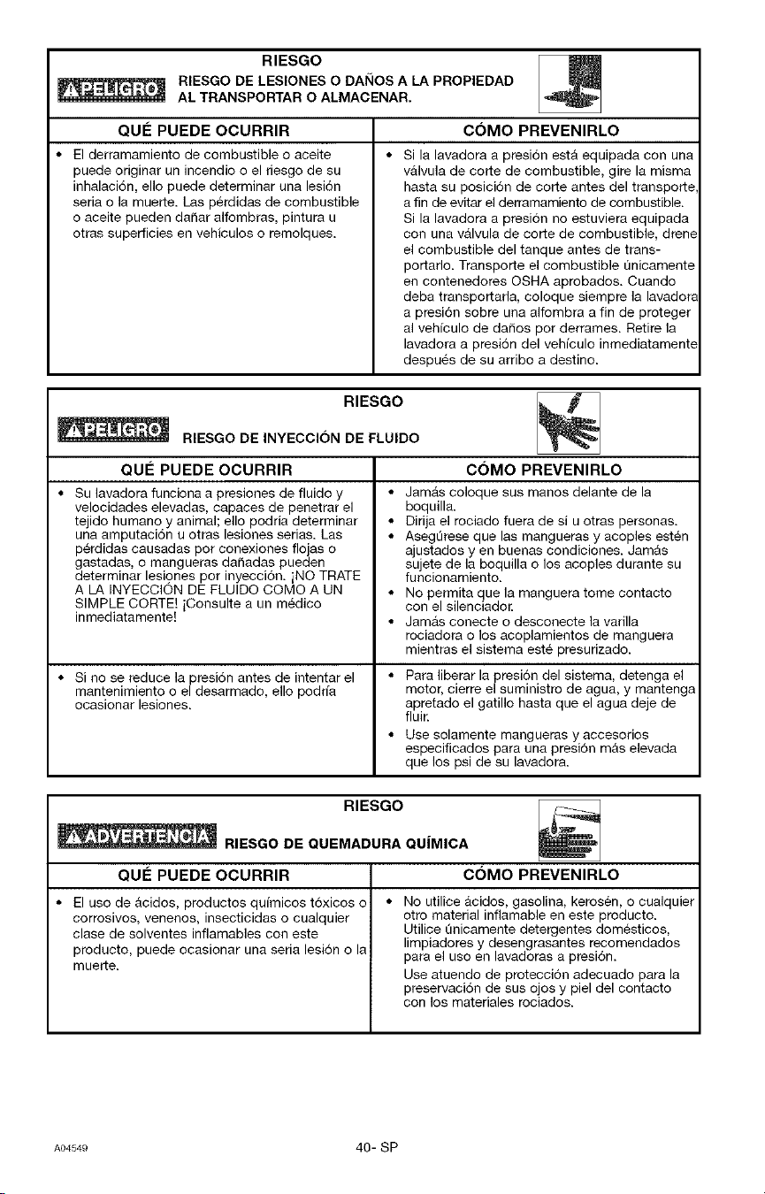
RIESGO
RIESGO DE LESIONES O DANOS A LA PROPIEDAD
AL TRANSPORTAR O ALMACENAR.
QUle PUEDE OCURRIR
• El derramamiento de combustible o aceite
puede originar un incendio o el riesgo de su
inhalacion, ello puede determinar una lesi6n
seria o la muerte. Las perdidas de combustible
o aceite pueden dafiar alfombras, pintura u
otras superficies en vehiculos o remolques.
COMO PREVENIRLO
Si la lavadora a presi6n esta equipada con una
valvula de corfe de combustible, gire la misma
hasta su posici6n de corfe antes del transporte
a fin de evitar el derramamiento de combustible.
Si la lavadora a presi6n no estuviera equipada
con una valvula de corte de combustible, drene
el combustible del tanque antes de trans-
portarlo. Transporte el combustible t_nicamente
en contenedores OSHA aprobados. Cuando
deba transporfarla, coloque siempre la lavadora
a presi6n sobre una alfombra a fin de proteger
al vehfculo de dafios por derrames. Retire la
lavadora a presi6n del vehfculo inmediatamente
despues de su arribo a destino.
RIESGO
RIESGO DE INYECClON DE FLUIDO
QUle PUEDE OCURRIR
• Su lavadora funciona a presiones de fiuido y
velocidades elevadas, capaces de penetrar el
tejido humano y animal; ello podria determinar
una amputacion u otras lesiones serias. Las
p@didas causadas por conexiones flojas o
gastadas, o mangueras dafiadas pueden
determinar lesiones por inyecci6n, iNO TRATE
A LA INYECCION DE FLUIDO COMO A UN
SIMPLE CORTE! iConsulte a un medico
inmediatamente[
• Si no se reduce la presion antes de intentar el
mantenimiento o el desarmado, ello podrfa
ocasionar lesiones.
COMO PREVENIRLO
• Jamas coloque sus manos delante de la
boquilla.
• Dirija el rociado fuera de si u otras personas.
• AsegQrese que las mangueras y acoples esten
ajustados yen buenas condiciones. Jamas
sujete de la boquilla o los acoples durante su
funcionamieeto.
• No permita que la manguera tome contacto
con el silenciador.
• Jamas conecte o desconecte la varilla
rociadora o los acoplamientos de manguera
mientras el sistema este presurizado.
• Para liberar la presion del sistema, detenga el
motor, cierre el suministro de agua, y mantenga
apretado el gatillo hasta que el agua deje de
fluir.
• Use solamente mangueras y accesorios
especificados para una presion mas elevada
que los psi de su lavadora.
RIESGO
_ RIESGO DE QUEMADURA QUIMICA
QUI_ PUEDE OCURRIR C(3MO PREVENIRLO
• El uso de acidos, productos qul'micos toxicos o
corrosivos, venenos, insecticidas o cualquier
clase de solventes infiamables con este
producto, puede ocasionar una seria lesion o la
muerte.
• No utilice acidos, gasolina, kerosen, o cualquier
otto material infiamable ee este producto.
Utilice Qnicamente detergentes domesticos,
limpiadores y desengrasantes recomeedados
para el uso en lavadoras a presi6n.
Use atueedo de proteccion adecuado para la
preservacion de sus ojos y piel del contacto
con los materiales rociados.
A04549 40- SP
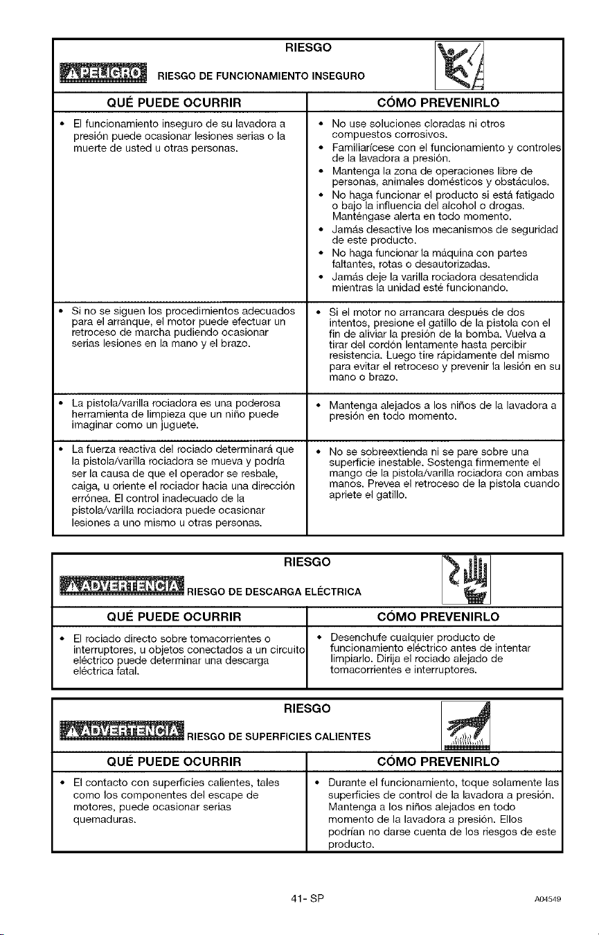
RIESGO
RIESGO DE FUNCIONAMIENTO INSEGURO
QUI_ PUEDE OCURRIR
• El funcionamieeto inseguro de su lavadora a
presi6n puede ocasionar lesiones serias o la
muerte de usted u otras personas.
• Si no se siguen los procedimientos adecuados
para el arranque, el motor puede efectuar un
retroceso de marcha pudieedo ocasionar
serias lesiones en la mano y el brazo.
• La pistola/varilla rociadora es una poderosa
herramienta de limpieza queun ni_o puede
imaginar como un juguete.
• La fuerza reactiva del rociado determinara que
la pistola/varilla rociadora se mueva y podrfa
ser la causa de que el operador se resbale,
caiga, u orieete el rociador hacia una direcci6n
erronea. El control inadecuado de la
pistola/varilla rociadora puede ocasionar
lesiones a uno mismo u otras personas.
COMO PREVENIRLO
• No use soluciones cloradas ni otros
compuestos corrosivos.
• Familiarfcese con el funcionamiento y controles
de la lavadora a presi6n.
• Manteega la zona de operaciones libre de
personas, animales domesticos y obstaculos.
• No haga funcionar el producto siesta fatigado
o bajo la influencia del alcohol o drogas.
Mantengase alerta ee todo momento.
• Jamas desactive los mecanismos de seguridad
de este producto.
• No haga funcionar la maquina con pares
faltantes, rotas o desautorizadas.
• Jamas deje la varilla rociadora desateedida
mientras la unidad este funcionando.
• Si el motor no arrancara despues de dos
intentos, presione el gatillo de la pistola con el
fin de aliviar la presion de la bomba. Vuelva a
tirar del cordon lentamente hasta percibir
resistencia. Luego tire rapidameete del mismo
para evitar el retroceso y preveeir la lesi6n en su
mano o brazo.
• Mantenga alejados a los ni_os de la lavadora a
presi6n en todo momento.
• No se sobreextienda ni se pare sobre una
superficie inestable. Sostenga firmemente el
mango de la pistola/varilla rociadora con ambas
manos. Prevea el retroceso de la pistola cuando
apriete el gatillo.
RIESGO
RIESGODEDESCARGAELC:CTRICA
QUEPUEDE OCURRIR
• El rociado directo sobre tomacorrientes o
interruptores, u objetos conectados a un circuito
electrico puede determinar una descarga
electrica fatal.
COMO PREVENIRLO
• Desenchufe cualquier producto de
funcionamiento electrico antes de intentar
limpiarlo. Dirija el rociado alejado de
tomacorrientes e interruptores.
RIESGO
_ RIESGODESUPERFICIESCALIENTES
QUI_ PUEDE OCURRIR COMO PREVENIRLO
• El contacto con superficies calientes, tales • Durante el funcionamiento, toque solamente las
como los componentes del escape de superficies de control de la lavadora a presion.
motores, puede ocasionar serias Manteega a los niSos alejados en todo
quemaduras, momeeto de la lavadora a presion. Ellos
podrfan no darse cuenta de los riesgos de este
producto.
41- SP A04549
RIESGO
_ RIESGODELESIONESPROVENIENTESDELROCIADO
QUle PUEDE OCURRIR COMO PREVENIRLO
• El rociado de los Iiquidos a alta velocidad
puede causar la rotura de algunos objetos
proyectando sus particulas violentamente.
• Los objetos livianos o los que no est@n
sujetos se pueden convertir en proyectiles
peligrosos.
• Use siempre anteojos de seguridad que cumplan
con la norma Z87 de ANSI. Use siempre ropa
especial para protegerse del rociado accidental.
• Nunca apunte la varilla rociadom ni roofe sobre
personas ni animales.
• Para evitar que se accione accidentalmente,
coloque siempre el seguro del gatillo cuando la
varilla rociadom no este en uso.
• JamAs fije el gati]lo permanentemente en la
posici6n presionada (abierta).
El chorro poderoso de su lavadora a presi6n es capaz de causar dafio
a superficies tales come la madera, vidrio, pintura del autombvil,
guardas rayadas, adornos y objetos delicados tales come flores y arbustos. Antes de rociar,
verifique el item que debe ser lavado para asegurarse que el mismo es suficientemente
fuerte como para resistir el impacto de la fuerza del rociado. Evite el use del chorro
concentrado excepto para superficies muy fuertes, tales como concreto y acero.
Hacer funcionar el equipo sin el flujo del agua Io dai_ara. Hacer funcionar la lavadora a
presi6n con su suministro de agua cerrado anulara su garantia. No debera hacerse
funcionar la lavadora a presion per mas de 2 minutes sin presionar el gatUlo que permite
entrar el agua fria a la bombay salir el agua caliente (reciclada).
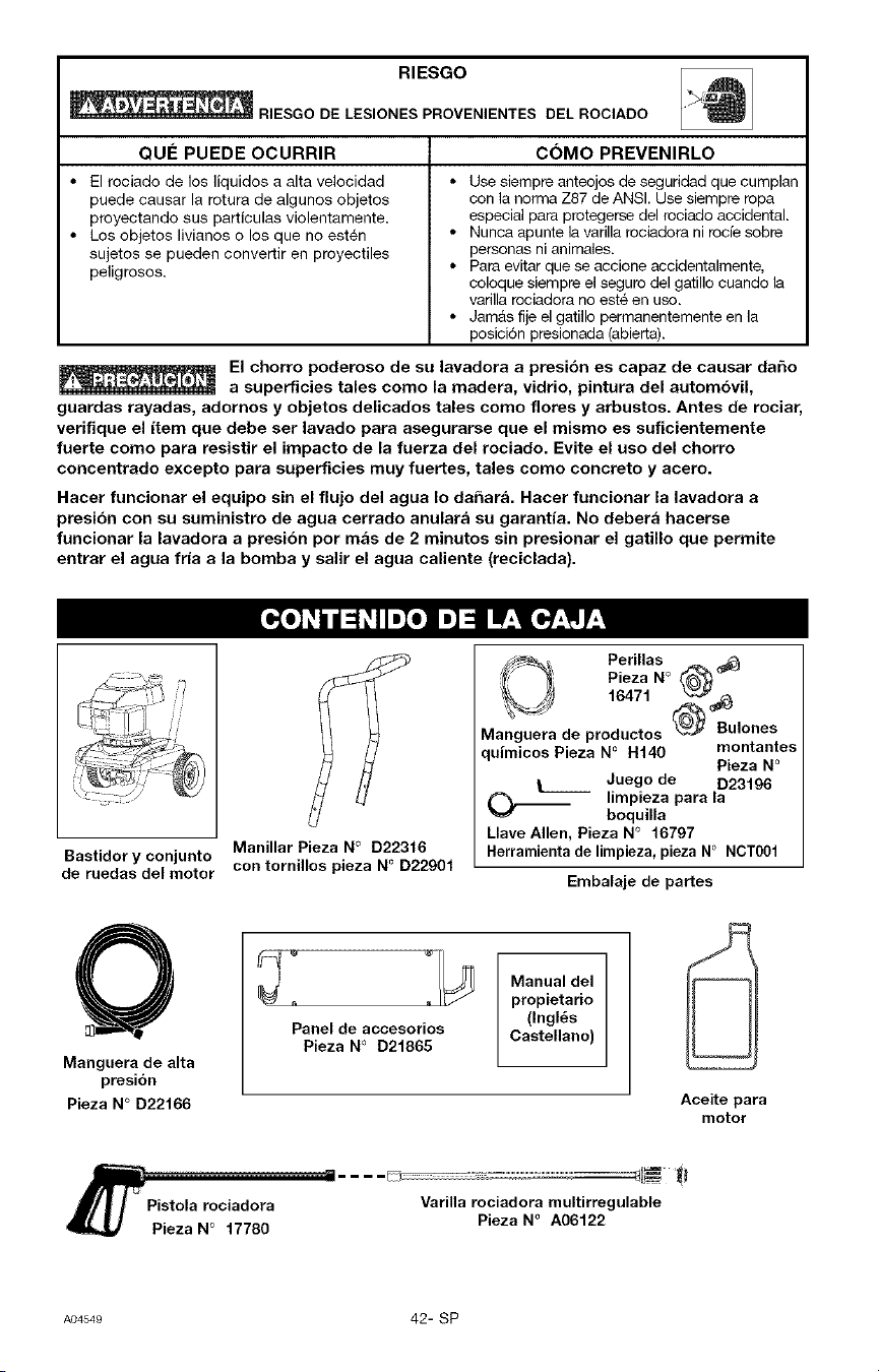
Manillar Pieza No D22316
Bastidor y conjunto
de ruedas del motor con tornillos pieza NOD22901
_ Perillas ,_
Pieza No _
16471 &_
de produotos _ Bulones
Manguera
quimicoe Pieza No I-I140 montantes
Pieza No
L_____ Juego de D23196
(_.__ limpieza para la
boquilla
Llave Allen, Pieza N° 16797
Herramienta de limpieza, pieza N° NCT001
Embalaje de partes
Manguera de alta
presi6n
Pieza N° D22166
Panel de accesorios
Pieza No D21865
Manual del
propietario
(Ingl6s
Castellano)
/r_ Pistola rociadora
Pieza N ° 17780
Varilla rociadora multirregulable
Pieza N ° A06122
Aceite para
motor
A04549 42- SP
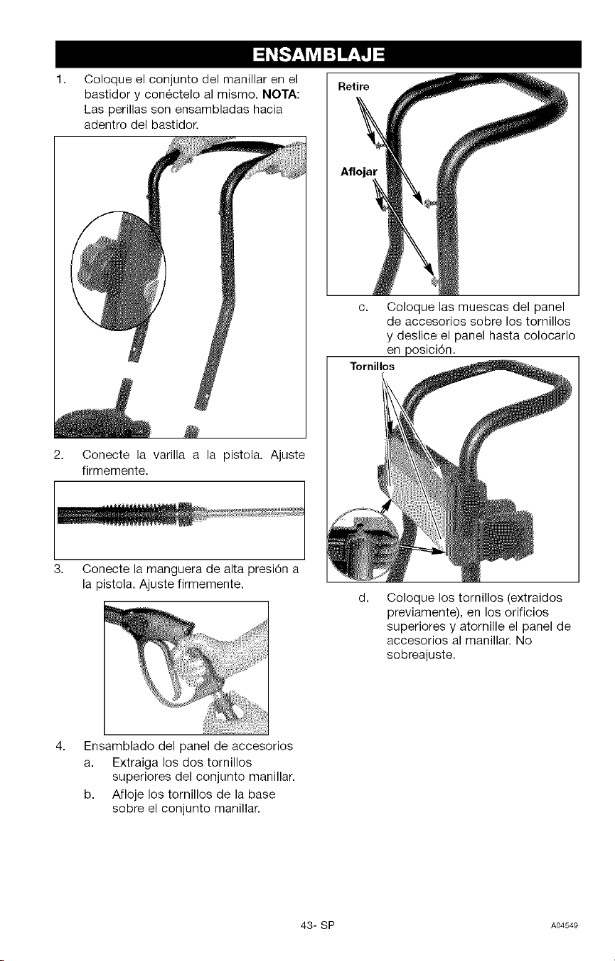
1. Retire
Coloque el conjunto del manillar en el
bastidor y conectelo al mismo. NOTA:
Las perillas son ensambladas hacia
adentro del bastidor.
c. Coloque las muescas del panel
de accesorios sobre los tomillos
y deslice el panel hasta colocarlo
en posici6n.
Tornillos
2. Conecte la varilla a la pistola. Ajuste
firmemente.
3,
Conecte la manguera de alta presi6n a
la pistola. Ajuste firmemente.
d,
Coloque los tornillos (extraidos
previamente), en los orificios
superiores y atornille el panel de
accesorios al manillar. No
sobreajuste.
Ensamblado del panel de accesorios
a. Extraiga los dos tornillos
superiores del conjunto manillar.
b. Afloje los tornillos de la base
sobre el conjunto manillar.
43- SP A04549
LEAESTEMANUALDEFUNCIONAMIENTOYSUSREGLASDESEGURIDAD,ANTESDE
HACERFUNCIONARLAUNIDAD.Comparelasilustracionesconsuunidadpara
familiarizarseconlaubicaci6ndesuscontrolesyregulaciones.Conserveestemanualpara
referenciasfuturas.
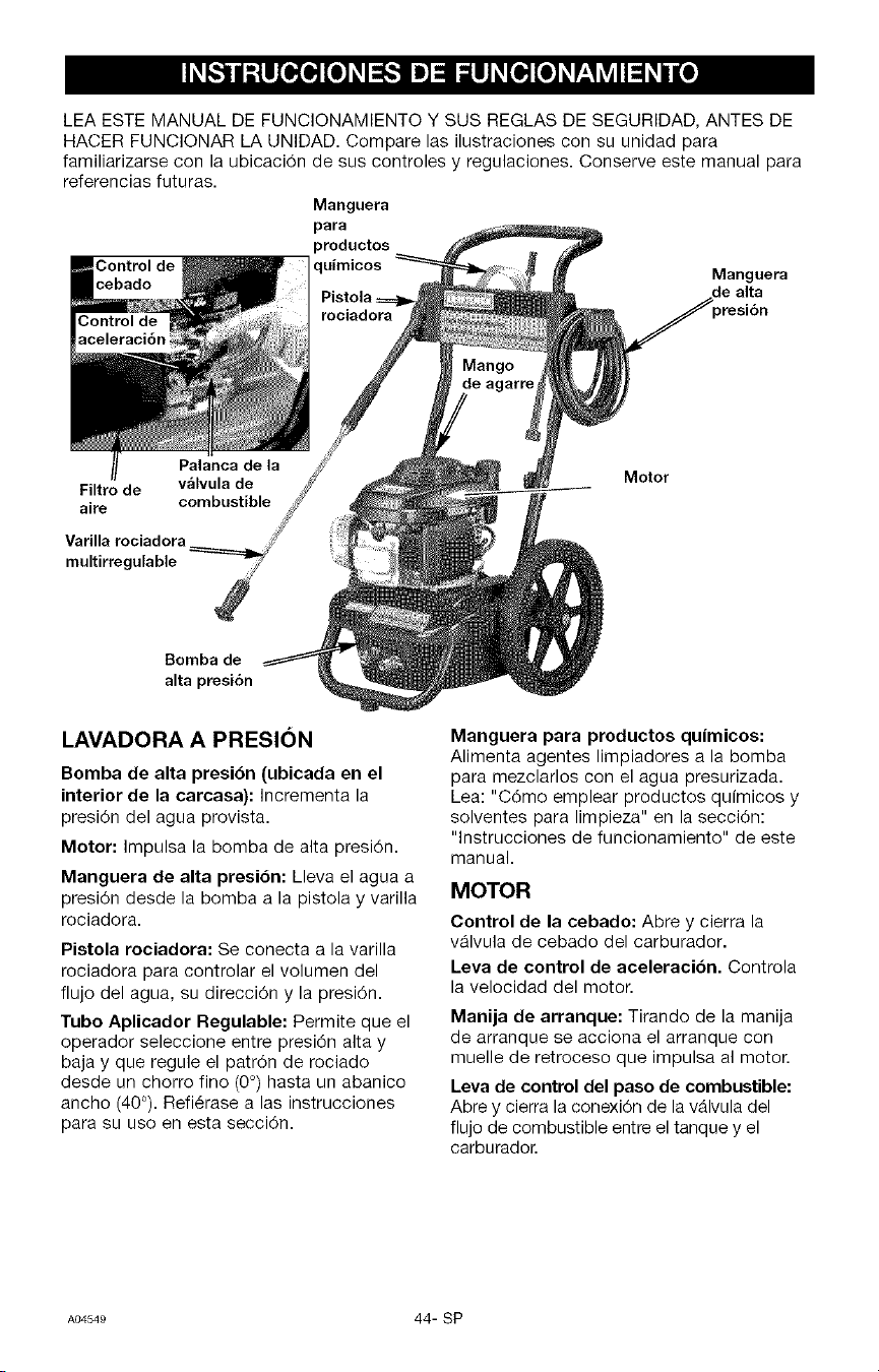
Manguera
para
productos
Control de
Manguera
cebado de alta
_resi6n
Filtro de
aire combustible
Varilla rociadora
multirregulable
Motor
Bomba de
alta presi6n
LAVADORA A PRESION
Bomba de alta presibn (ubicada en el
interior de la carcasa): Incrementa la
presi6n del agua provista.
Motor: Impulsa la bomba de alta presi6n.
Manguera de alta presi6n: Lleva el agua a
presi6n desde la bomba a la pistola y varilla
rociadora.
Pistola rociadora: Se conecta a la varilla
rociadora para controlar el volumen del
flujo del agua, su direcci6n y la presi6n.
Tubo Aplicador Regulable: Permite que el
operador seleccione entre presi6n alta y
baja y que regule el patr6n de rociado
desde un chorro fino (0°) hasta un abanico
ancho (40°). Refi6rase alas instrucciones
para su uso en esta secci6n.
Manguera para productos quimicos:
Alimenta agentes limpiadores a la bomba
para mezclarlos con el agua presurizada.
Lea: "C6mo emplear productos quimicos y
solventes para limpieza" en la secci6n:
"lnstrucciones de funcionamiento" de este
manual.
MOTOR
Control de la cebado: Abre y cierra la
v_lvula de cebado del carburador.
Leva de control de aceleraci6n. Controla
la velocidad del motor.
Manija de arranque: Tirando de la manija
de arranque se acciona el arranque con
muelle de retroceso que impulsa al motor.
Leva de control del paso de combustible:
Abre y cierra la conexi6n de la v_lvula del
flujo de combustible entre el tanque y el
carburador.
A04549 44- SP
TERMINOLOGiA DE LA LAVADORA
A PRESION
PSh (Pounds per Square Inch) Lb/Pulg 2. Es
una unidad de medida para la presi6n del
agua. Tambi@n se usa para medir la presi6n
neumAtica, presi6n hidrAulica, etc. Equivale
a 49 pascales.
GPM: (Gallons per Minute). Galones por
rninuto. Es la unidad de rnedida para el
flujo de agua. Equivale a 3,8 L/min.
CU: (Unidades de limpieza) GPM
multiplicadas por psi.
GPM x PSI = Unidades limpiadoras
Modo de Derivacibn: Permite que el agua
recircule dentro de la bomba cuando el
gatillo no est_ presionado.
No permita que la
unidad funcione
por mas de dos minutos sin apretar el
gatillo porque se recalentara y se dahara
bomba.
Sistema de Inyeccibn de Productos
Quimicos: Mezcla los limpiadores o
solventes con agua para mejorar la
eficiencia del lavado.
Suministro de agua: Todas las lavadoras a
presi6n deben tener un suministro de agua.
Los requerimientos mfnimos para el
suministro del agua son 20 PSI y 22,7 L/min
(5 Gal/min).
COMO USAR
IMPORTANTE: Lea y comprenda c6mo
usar la presi6n de la lavadora antes de
operarla,
REGULACION DE LA PRESION
Los valores de calibrado de la presi6n
vienen regulados de fb.brica, con el objeto
de Iograr la presi6n 6ptima para la limpieza.
Si usted necesitase reducir la presi6n, ello
podrA Iograrse merced a los siguientes
m@todos:
1. Retirese de la superficie que ha de
limpiarse. Cuanto mAs alejado usted se
encuentre de la misma, menor presi6n
habr_ sobre la superficie que deberA
limpiar.
2. Rote la boquilla del extremo de la
varilla rociadora multirregulable, para
ensanchar el abanico de rociado. El
rociado mAs ancho minimizar_ la
presi6n sobre la superficie que ha de
ser limpiada.
NO intente
incrementar la
presibn de la bomba. Un calibrado
superior al que trae de fabrica puede
da_ar la bomba.
COMO UTILIZAR EL TUBO
APLICADOR:
Su lavadora a presi6n est_ equipada con
un tubo aplicador con boquilla
multirregulable para baja y alta presi6n. La
presi6n alta es para lavado y enjuague,
mientras que la presi6n baja es para aplicar
productos quimicos o soluciones para
lavado de superficies.
AI usar la presibn alta,
NO permita que el
chorro haga contacto con la piel
desprotegida, ojos, mascotas o
animales; porque podria causar lesiones
serias.
Riesgo de
inyeccibn o lesibn
a las personas; NO dirija el chorro de
descarga hacia persona alguna.
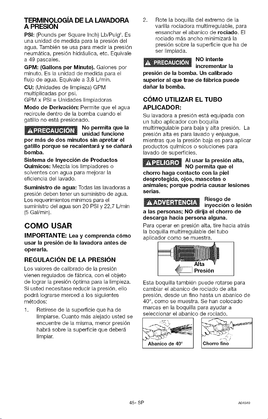
Para operar en presi6n alta, tire hacia atr_s
la boquilla multirregulable del tubo
aplicador como se muestra.
Alta
Esta boquilla tambi@n puede rotarse para
cambiar el abanico de rociado de alta
presi6n, desde un fino hasta un abanico de
40 °, como se muestra. Se han colocado
marcas en la boquilla para ayudar a
seleccionar el abanico de rociado.
_ ,anic,_aoJ_e400 _[_/_._,_=-_
45- SP AO4S4e
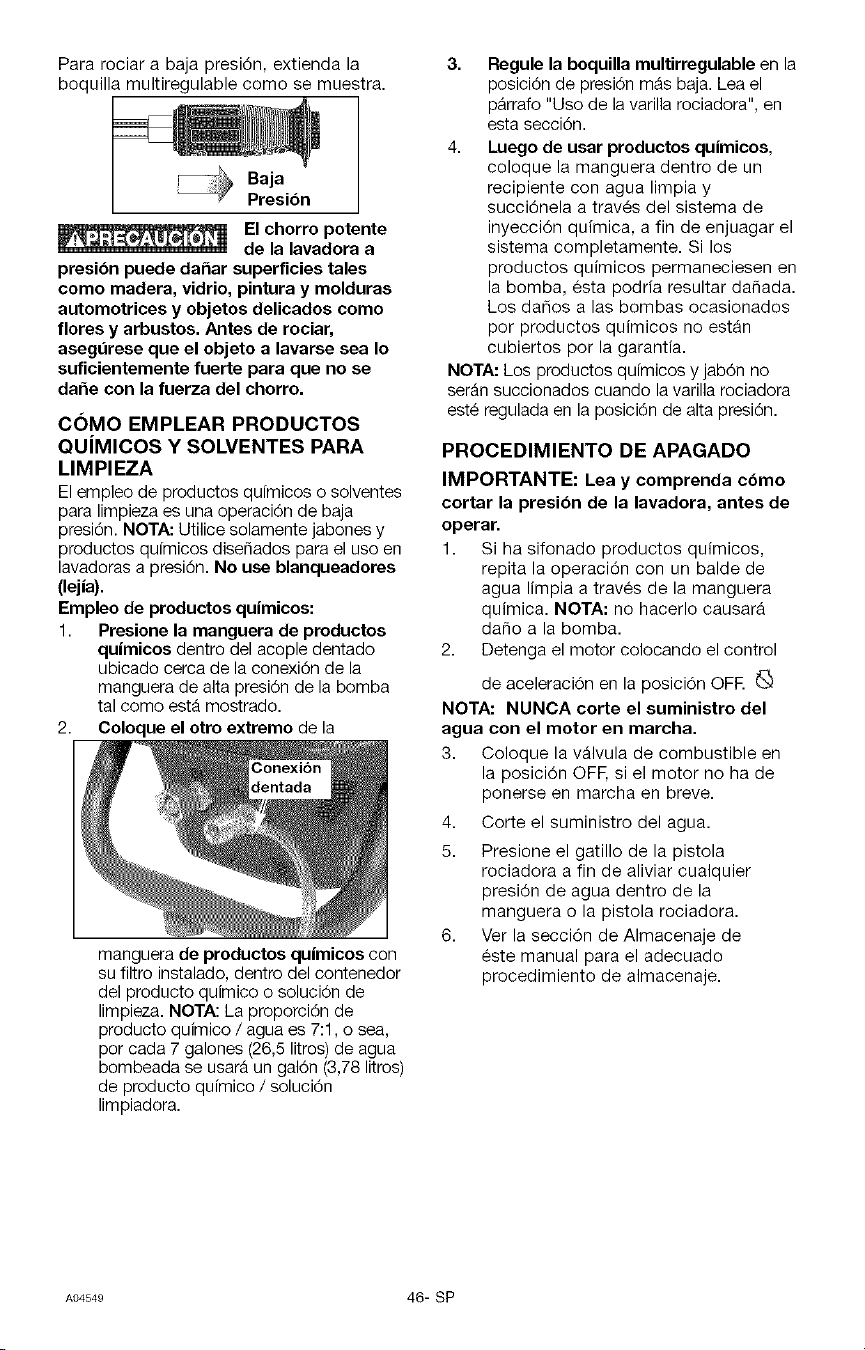
Para rociar a baja presi6n, extienda la
boquilla multiregulable como se muestra.
Baja
Presi6n
El chorro potente
de la lavadora a
presibn puede dahar superficies tales
como madera, vidrio, pintura y molduras
automotrices y objetos delicados como
flores y arbustos. Antes de rociar,
asegdrese que el objeto a lavarse sea Io
suficientemente fuerte para que no se
da_e con la fuerza del chorro.
COMO EMPLEAR PRODUCTOS
QUiMICOS Y SOLVENTES PARA
LIMPIEZA
El empleo de productos qdrnicos o solventes
para limpieza es una operaci6n de baja
presi6n. NOTA: Utilice solamente jabones y
productos qufmicos disefiados para el uso en
lavadoras a presi6n. No use blanqueadores
(lejia).
Empleo de productos quimicos:
1. Presione la manguera de productos
quimicos dentro del acople dentado
ubicado cerca de la conexi6n de la
manguera de alta presi6n de la bomba
tal como est_ mostrado.
2. Coloque el otro extremo de la
manguera de productos qu|micos con
su filtro instalado, dentro del contenedor
del producto quimico o soluci6n de
limpieza. NOTA: La proporci6n de
producto quimico / agua es 7:1, o sea,
por cada 7 galones (26,5 litros) de agua
bombeada se usar_ un gal6n (3,78 litros)
de producto qufmico / soluci6n
limpiadora.
3. Regule la boquilla multirregulable en la
posici6n de presi6n m_s baja. Lea el
pArrafo "Uso de la varilla rociadora", en
esta secci6n.
4. Luego de usar productos quimicos,
coloque la manguera dentro de un
recipiente con agua limpia y
succi6nela a trav_s del sistema de
inyecci6n quimica, a fin de enjuagar el
sistema completamente. Si los
productos quimicos permaneciesen en
la bomba, esta podria resultar dafiada.
Los dafios a las bombas ocasionados
por productos quimicos no estAn
cubiertos por la garantia.
NOTA: Los productos qufmicos y jab6n no
ser_n succionados cuando la varilla rociadora
est_ regulada en la posici6n de alta presi6n.
PROCEDIMIENTO DE APAGADO
IMPORTANTE: Lea y comprenda cbmo
cortar la presi6n de la lavadora, antes de
operar.
1. Si ha sifonado productos quimicos,
repita la operaci6n con un balde de
agua limpia a trav6s de la manguera
quimica. NOTA: no hacerlo causarA
dafio a la bomba.
2. Detenga el motor colocando el control
de aceleraci6n en la posici6n OFR _:_
NOTA: NUNCA corte el suministro del
agua con el motor en marcha.
3. Coloque la v_lvula de combustible en
la posici6n OFE si el motor no ha de
ponerse en marcha en breve.
4. Corte el suministro del agua.
5. Presione el gatillo de la pistola
rociadora a fin de aliviar cualquier
presi6n de agua dentro de la
manguera o la pistola rociadora.
6. Ver la secci6n de Almacenaje de
este manual para el adecuado
procedimiento de almacenaje.
A04549 46- SP
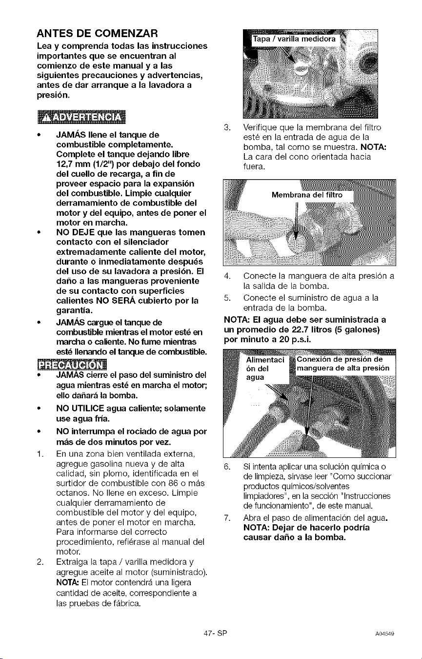
ANTES DE COMENZAR
Lea y comprenda todas las instrucciones
importantes que se encuentran al
comienzo de este manual y a las
siguientes precauciones y advertencias,
antes de dar arranque a la lavadora a
presibn.
• JAMAS Ilene el tanque de
combustible completamente.
Complete el tanque dejando libre
12,7 mm (1/2") por debajo del rondo
del cuello de recarga, a fin de
proveer espacio para la expansi6n
del combustible. Limpie cualquier
derramamiento de combustible del
motor y del equipo, antes de poner el
motor en marcha.
• NO DEJE que las mangueras tomen
contacto con el silenciador
extremadamente caliente del motor,
durante o inmediatamente despuds
del uso de su lavadora a presi6n. El
daho a las mangueras proveniente
de su contacto con superficies
calientes NO SERA cubierto por la
garantia.
• JAM,_S cargue el tanque de
combuslJble mienl_as el motor estd en
marcha o caliente. No fume mientras
estd Ilenando el tanque de combustible.
• JAMAS cierre el paso del suministro del
agua mientras este en marcha el motor;
ello dahara la bomba.
• NO UTILICE agua caliente; solamente
use agua fria.
• NO interrumpa el rociado de agua por
mas de dos minutos por vez.
1. En una zona bien ventilada externa,
agregue gasolina nueva y de alta
calidad, sin plomo, identificada en el
surtidor de combustible con 86 o mAs
octanos. No Ilene en exceso. Limpie
cualquier derramamiento de
combustible del motor y del equipo,
antes de poner el motor en marcha.
Para informarse del correcto
procedimiento, refi6rase al manual del
motor
2. Extraiga la tapa / varilla medidora y
agregue aceite al motor (suministrado).
NCTA: El motor contendr_ una ligera
cantidad de aceite, correspondiente a
las pruebas de f_brica.
medidora
3,
Verifique que la membrana del filtro
est6 en la entrada de agua de la
bomba, tal como se muestra. NOTA:
La cara del cono orientada hacia
fuera.
4. Conecte la manguera de alta presi6n a
la salida de la bomba.
5. Conecte el suministro de agua a la
entrada de la bomba.
NOTA: El agua debe ser suministrada a
un promedio de 22.7 litros (5 galones)
por minuto a 20 p.s.i.
6. Si intenta aplicar una soluci6n quimica o
de limpieza, sirvase leer "Como succionar
productos quimicos/solventes
limpiadores", en la seccion "lnstrucciones
de funcionamiento", de este manual.
7. Abra el paso de alimentaci6n del agua.
NOTA: Dejar de hacerlo podria
causar da_o a la bomba.
47- SP AO4S4e
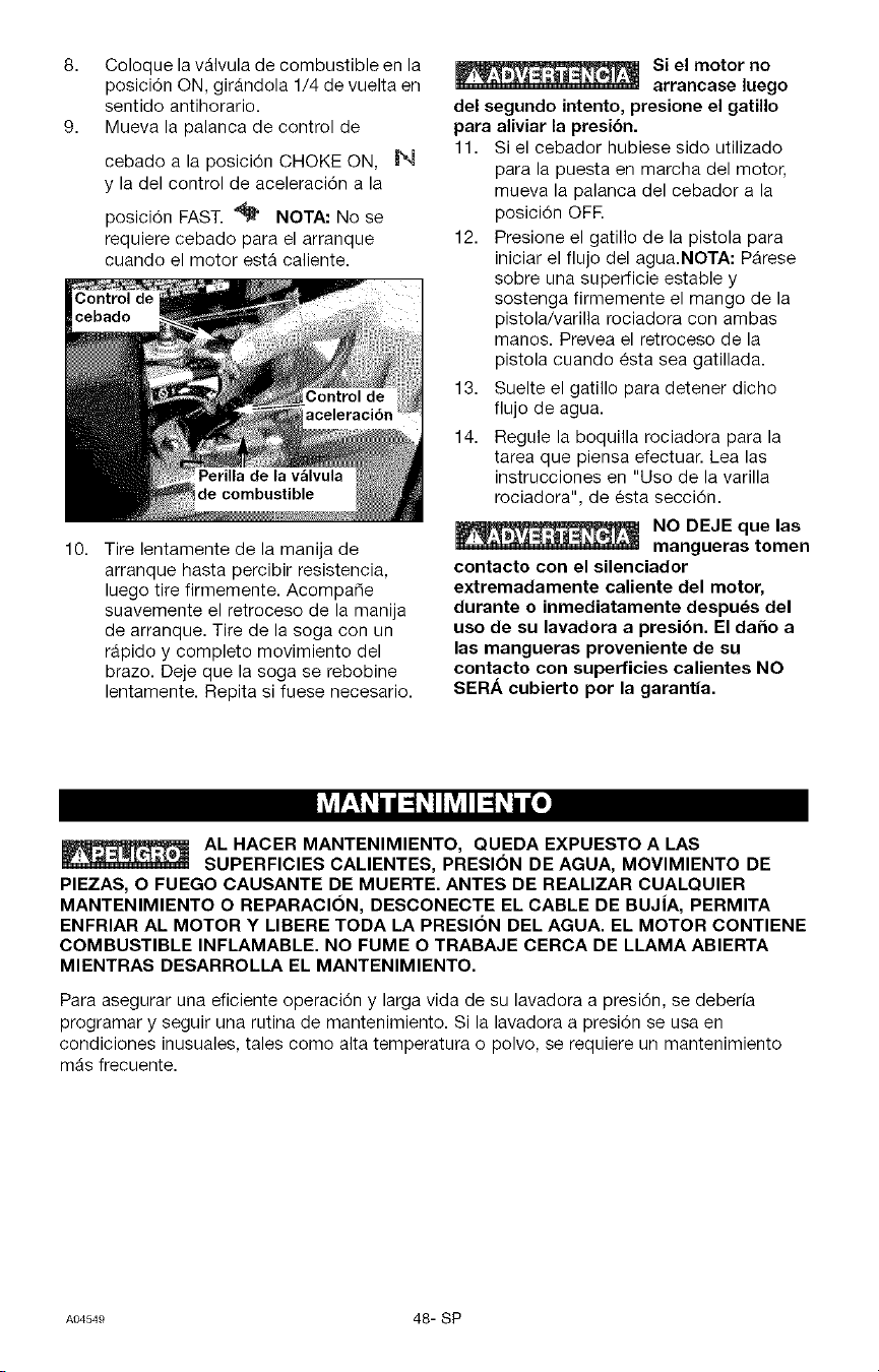
8,
9.
10.
Coloque la vAIvula de combustible en la
posici6n ON, gir_ndola 1/4 de vuelta en
sentido antihorario.
Mueva la palanca de control de
cebado a la posici6n CHOKE ON, _1
y la del control de aceleraci6n a la
posici6n FAST. "_ NOTA: No se
requiere cebado para el arranque
cuando el motor est_ caliente.
de combustible
Tire lentamente de la manija de
arranque hasta percibir resistencia,
luego tire firmemente. Acompa_e
suavemente el retroceso de la manija
de arranque. Tire de la soga con un
rApido y completo movimiento del
brazo. Deje que la soga se rebobine
lentamente. Repita si fuese necesario.
Si el motor no
arrancase luego
del segundo intento, presione el gatillo
para aliviar la presibn.
11. Si el cebador hubiese sido utilizado
para la puesta en marcha del motor,
mueva la palanca del cebador a la
posici6n OFE
12. Presione el gatillo de la pistola para
iniciar el flujo del agua.NOTA: P_rese
sobre una superficie estable y
sostenga firmemente el mango de la
pistola/varilia rociadora con ambas
rnanos. Prevea el retroceso de la
pistola cuando _sta sea gatillada.
13. Suelte el gatillo para detener dicho
flujo de agua.
14. Regule la boquilla rociadora para la
tarea que piensa efectuar. Lea las
instrucciones en "Uso de la varilla
rociadora", de esta secci6n.
NO DEJE que las
mangueras tomen
contacto con el silenciador
extremadamente caliente del motor,
durante o inmediatamente despues del
uso de su lavadora a presibn. El daho a
las mangueras proveniente de su
contacto con superficies calientes NO
SERA cubierto per la garantia.
Lv_E__i d=1_IhVJI=1_i d_e]
AL HACER MANTENIMIENTO, QUEDA EXPUESTO A LAS
SUPERFICIES CALIENTES, PRESlON DE AGUA, MOVIMIENTO DE
PIEZAS, O FUEGO CAUSANTE DE MUERTE. ANTES DE REALIZAR CUALQUIER
MANTENIMIENTO O REPARACION, DESCONECTE EL CABLE DE BUJiA, PERMITA
ENFRIAR AL MOTOR Y LIBERE TODA LA PRESlON DEL AGUA. EL MOTOR CONTIENE
COMBUSTIBLE INFLAMABLE. NO FUME O TRABAJE CERCA DE LLAMA ABIERTA
MIENTRAS DESARROLLA EL MANTENIMIENTO.
Para asegurar una eficiente operaci6n y larga vida de su lavadora a presi6n, se deberia
programar y seguir una rutina de mantenimiento. Si la lavadora a presi6n se usa en
condiciones inusuales, tales como alta temperatura o polvo, se requiere un mantenimiento
mAs frecuente.
A_549 48-SP
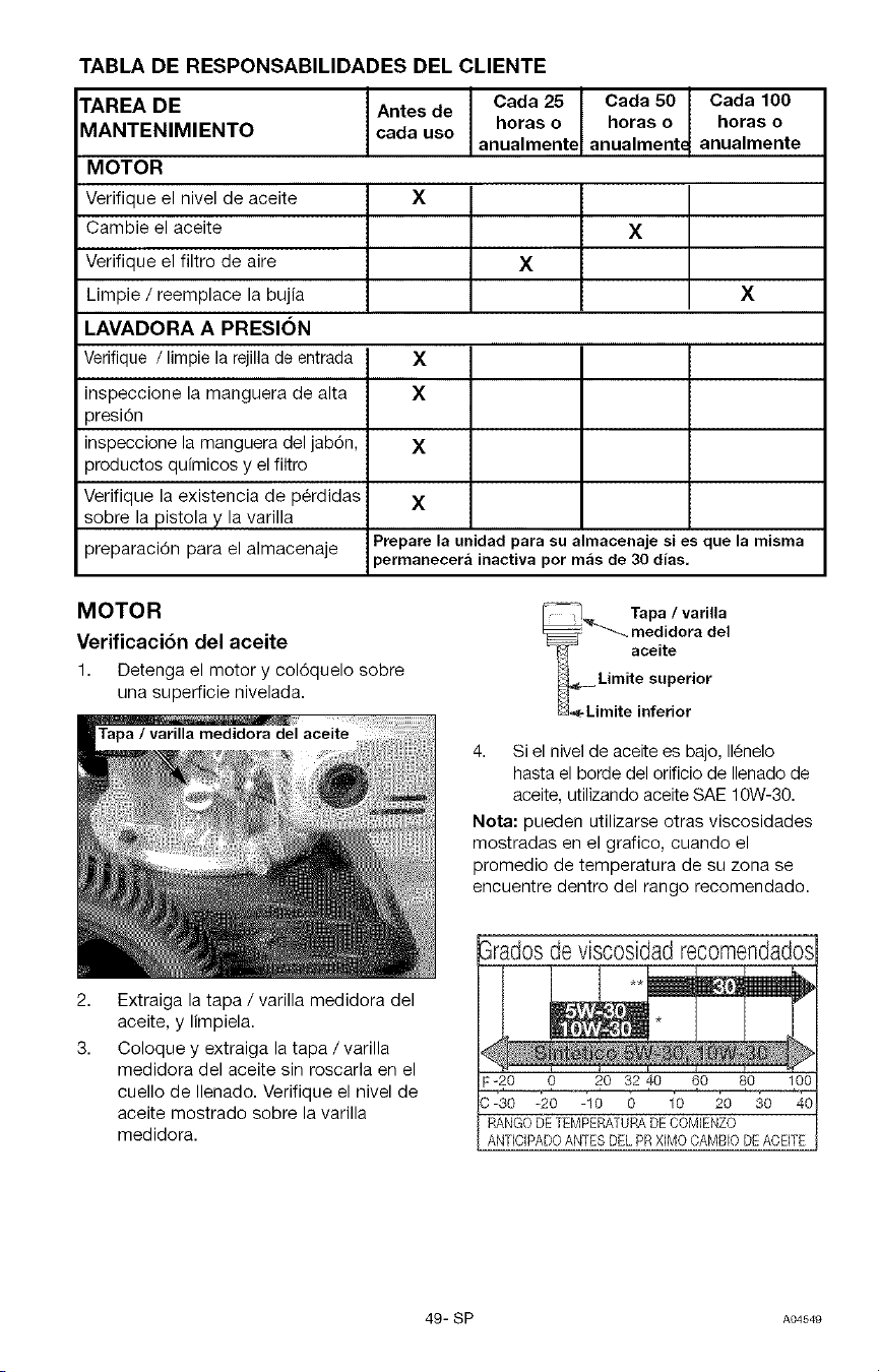
TABLA DE RESPONSABILIDADES DEL CLIENTE
TAREA DE
MANTENIMIENTO
MOTOR
Verifique el nivel de aceite
Cambie el aceite
Verifique el filtro de aire
Limpie / reemplace la bujia
LAVADORA A PRESION
Verifique / limpie la rejilla de entrada
inspeccione la manguera de alta
presi6n
inspeccione la manguera del jab6n,
productos quimicos y el filtro
Verifique la existencia de p6rdidas
sobre la pistola y la varilla
preparaci6n para el almacenaje
Antes de
cada use
Cada 25
horas o
anualmente
Cada 50
horas o
anualment_
Cada 100
horas o
anualmente
X
X
X
X
X
X
X
X
Prepare la unidad para su almacenaje si es que la misma
permanecer_ inactiva por mas de 30 dias,
MOTOR
Verificaci6n del aceite
1. Detenga el motor y col6quelo sobre
una superficie nivelada.
del aceite
2,
3.
Extraiga la tapa / varilla medidora del
aceite, y limpiela.
Coloque y extraiga la tapa /varilla
medidora del aceite sin roscarla en el
cuello de Ilenado. Verifique el nivel de
aceite mostrado sobre la varilla
medidora.
Tapa / varilla
_---_ medidora del
-_ aceite
4. Si el nivel de aceite es bajo, 116nelo
hasta el borde del orificio de Ilenado de
aceite, utilizando aceite SAE 10W-30.
Nora: pueden utilizarse otras viscosidades
mostradas en el grafico, cuando el
promedio de temperatura de su zona se
encuentre dentro del rango recomendado.
3radosde visc0sidadrecomendados
v
NN
F-20 0 20 32 40 60 80 100
RANGO DE TEMPERATURA DE COMIENZO
ANTICIPADOANTESDELPRXIMOCANBIODEAOBTE
49- SP A04549
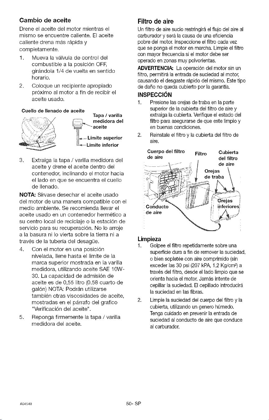
Cambio de aceite
Drene el aceite del motor mientras el
mismo se encuentre caliente. El aceite
caliente drena m_s rApida y
completamente.
1. Mueva la vAIvula de control del
combustible a la posici6n OFE
girfindola 1/4 de vuelta en sentido
horario.
2. Coloque un recipiente apropiado
pr6ximo al motor a fin de recibir el
aceite usado.
Cuelio de Ilenado de aceite
Tapa / varilla
i--/ medidora del
'_"- ace ite
_J._= Limite superior
_3-.=-Limite inferior
3. Extraiga la tapa / varilla medidora del
aceite y drene el aceite dentro del
contenedor, inclinando el motor hacia
el lado en que se encuentra el cuello
de Ilenado.
NOTA: Sfrvase desechar el aceite usado
del motor de una manera compatible con el
medio ambiente. Se recomienda Ilevar el
aceite usado en un contenedor hermetico a
su centro local de reciclaje o la estaci6n de
servicio para su recuperaci6n. No Io arroje
a la basura ni Io vier_a sobre la tierra ni a
trav_s de la tuberfa del desagQe.
4. Con el motor en una posici6n
nivelada, Ilene hasta el limite de la
marca superior mostrada en la varilla
medidora, utilizando aceite SAE 10W-
30. La capacidad de admisi6n de
aceite es de 0,55 litro (0.58 cuarto de
gal6n) NOTA: PodrAn utilizarse
tambien otras viscosidades de aceite,
mostradas en el pArrafo del grafico
"Verificaci6n del aceite".
5. Reponga firmemente la tapa / varilla
medidora del aceite.
Filtro de aire
Un filtro de aire sucio restringirA el flujo del aire al
carburador y sera la causa de una eficiencia
pobre del motor. Inspeccione el filtro cada vez
que se ponga el motor en marcha. Limpie el filtro
con mayor frecuencia si el motor debe ser
operado en zonas muy polvorientas.
ADVERTENCIA: La operacidn del motor sin un
filtro, permitirfl la entrada de suciedad al motor,
causando el desgaste rflpido del mismo. Estetipo
de daSo no queda cubierto por la garantfa.
INSPECCION
1. Presione las orejas de traba en la parte
superior de la cubierta del filtro de aire y
extraiga la cubierta. Verifique el estado del
filtro para asegurarse de que este limpio y
en buenas condiciones.
2. Reinstale el filtro y la cubierta delfiltro de
aire.
Cuerpo del filtro Filtro Cubierta
de aire del filtro
de aire
Orejas
de traba
de aire
Limpieza
1. Golpee el filtro repetidarnente sobre una
superficie dura a fin de remover la suciedad,
o bien sopletee con aire comprimido (sin
exceder las 30 psi (207 kPA, 1,2 Kg/cm 2)a
traves del filtro, desde el lado limpio que se
orienta hacia el motor. Jamfls intente de
cepillar la suciedad. El cepillado introducirfl
la suciedad en las fibras.
2. Limpie la suciedad del cuerpo del filtro y la
cubierta, utilizando un genero hQmedo.
Tenga cuidado en prevenir la entrada de
suciedad al conducto de aire que conduce
al carburador.
A_549 50-SP
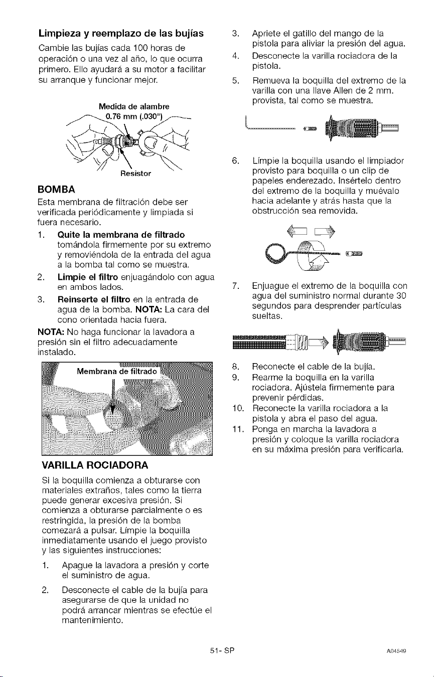
Limpieza y reemplazo de las bujias
Cambie las bujias cada 100 horas de
operaci6n o una vez al afio, Io que ocurra
primero. EIIo ayudar_ a su motor a facilitar
su arranque y funcionar mejor.
Medida de alambre
0.76 mm (.030")_
Resistor
BOMBA
Esta membrana de filtraci6n debe ser
verificada peri6dicamente y limpiada si
fuera necesario.
1. Quite la membrana de filtrado
tom_ndola firmemente por su extremo
y removi_ndola de la entrada del agua
a la bomba tal como se muestra.
2. Limpie el filtro enjuagAndolo con agua
en ambos lados.
3. Reinserte el filtro en la entrada de
agua de la bomba. NOTA: La cara del
cono orientada hacia fuera.
NOTA: No haga funcionar la lavadora a
presi6n sin el filtro adecuadamente
instalado.
Membrana de filtrado
VARILLA ROCIADORA
3,
4.
5.
Apriete el gatillo del mango de la
pistola para aliviar la presi6n del agua.
Desconecte la varilla rociadora de la
pistola.
Remueva la boquilla del extremo de la
varilla con una Ilave Allen de 2 mm.
provista, tal como se muestra.
Limpie la boquilla usando el limpiador
provisto para boquilla o un clip de
papeles enderezado. Insertelo dentro
del extremo de la boquilla y muevalo
hacia adelante y atrAs hasta que la
obstrucci6n sea removida.
Enjuague el extremo de la boquilla con
agua del suministro normal durante 30
segundos para desprender partfculas
sueltas.
8. Reconecte el cable de la bujia.
9. Rearme la boquilla en la varilla
rociadora. AjQstela firmemente para
prevenir p_rdidas.
10. Reconecte la varilla rociadora a la
pistola y abra el paso del agua.
11. Ponga en marcha la lavadora a
presi6n y coloque la varilla rociadora
en su maxima presi6n para verificarla.
Si la boquilla comienza a obturarse con
materiales extrafios, tales como la tierra
puede generar excesiva presi6n. Si
comienza a obturarse parcialmente o es
restringida, la presi6n de la bomba
comezarA a pulsar. Limpie la boquilla
inmediatamente usando el juego provisto
y las siguientes instrucciones:
1. Apague la lavadora a presi6n y corte
el suministro de agua.
2. Desconecte el cable de la bujia para
asegurarse de que la unidad no
podrA arrancar mientras se efectQe el
mantenimiento.
51- SP A04549
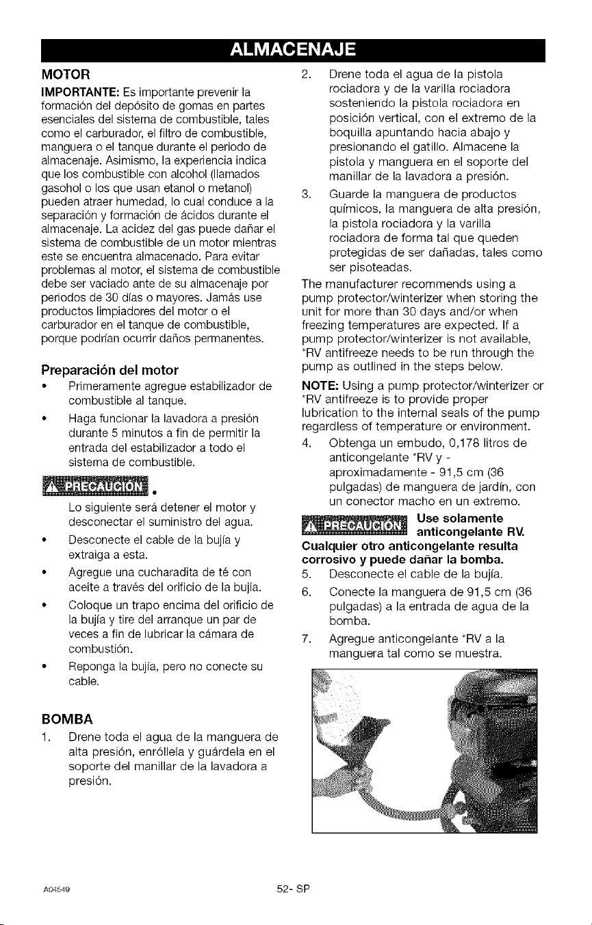
MOTOR
IMPORTANTE: Ee importante prevenir la
formaci0n del dep6sito de gomas en partes
esenciales del sistema de combustible, tales
como el carburador, el filtro de combustible,
manguera o el tanque durante el periodo de
almacenaje. Asimismo, la experiencia indica
que los combustible con alcohol (llamados
gasohol o los que usan etanol o metanol)
pueden atraer humedad, Io cual conduce a la
separaci6n y formacion de _cidos durante el
almacenaje. La acidez del gas puede daflar el
sistema de combustible de un motor mientras
este se encuentra almacenado. Para evitar
problemas al motor, el sistema de combustible
debe ser vaciado ante de su almacenaje por
periodos de 30 dias o mayores. JamAs use
productos limpiadores del motor o el
carburador en el tanque de combustible,
porque podrfan ocurrir daflos permanentes.
Preparacion del motor
• Primeramente agregue estabilizador de
combustible al tanque.
• Haga funcionar la lavadora a presi6n
durante 5 minutos a fin de permitir la
entrada del estabilizador a todo el
sistema de combustible.
Lo siguiente ser& detener el motor y
desconectar el suministro del agua.
• Desconecte el cable de la bujfa y
extraiga a esta.
• Agregue una cucharadita de t6 con
aceite a trav6s del orificio de la bujia.
• Coloque un trapo encima del orificio de
la bujia y tire del arranque un par de
veces a fin de lubricar la cAmara de
combustion.
• Reponga la bujia, pero no conecte su
cable.
2. Drene toda el agua de la pistola
rociadora y de la varilla rociadora
sosteniendo la pistola rociadora en
posici6n vertical, con el extremo de la
boquilla apuntando hacia abajo y
presionando el gatillo. Almacene la
pistola y manguera en el soporte del
manillar de la lavadora a presi6n.
3. Guarde la manguera de productos
qufmicos, la manguera de alta presi6n,
la pistola rociadora y la varilla
rociadora de forma tal que queden
protegidas de ser dafiadas, tales como
ser pisoteadas.
The manufacturer recommends using a
pump protector/winterizer when storing the
unit for more than 30 days and/or when
freezing temperatures are expected. If a
pump protector/winterizer is not available,
*RV antifreeze needs to be run through the
pump as outlined in the steps below.
NOTE: Using a pump protector/winterizer or
*RV antifreeze is to provide proper
lubrication to the internal seals of the pump
regardless of temperature or environment.
4. Obtenga un embudo, 0,178 litros de
anticongelante *RV y -
aproximadamente - 91,5 cm (36
pulgadas) de manguera de jardin, con
un conector macho en un extremo.
Use solamente
anticongelante RV.
Cualquier otro anticongelante resulta
corrosivo y puede dahar la bomba.
5. Desconecte el cable de la bujfa.
6. Conecte la manguera de 91,5 cm (36
pulgadas) a la entrada de agua de la
bomba.
7. Agregue anticongelante *RV a la
manguera tal como se muestra.
BOMBA
1. Drene toda el agua de la manguera de
alta presi6n, enr611elay gu_rdela en el
soporte del manillar de la lavadora a
presi6n.
A04549 52- SP
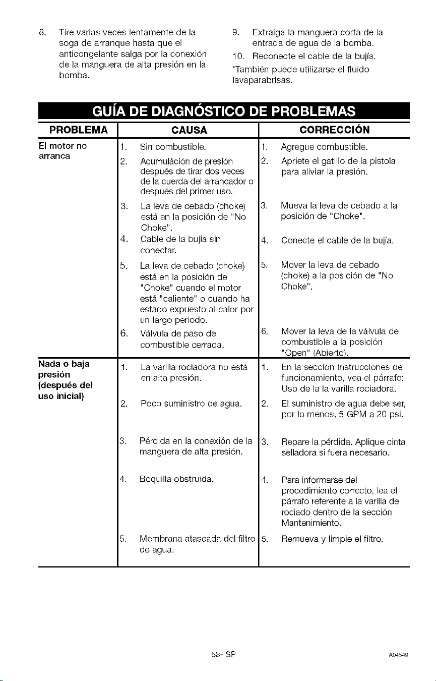
Tire varias veces lentamente de la
soga de arranque hasta que el
anticongelante salga por la conexi6n
de la manguera de alta presi6n en la
bomba.
9. Extraiga la manguera corta de la
entrada de agua de la bomba.
10. Reconecte el cable de la bujfa.
*Tambi6n puede utilizarse el fluido
lavaparabrisas.
PROBLEMA
El motor no
arranca
Nada o baja
presibn
(despuds del
uso inicial)
CAUSA
1. Sin combustible.
2. AcumulAci6n de presi6n
despu_s de tirar dos veces
de la cuerda del arrancador o
despu_s del primer use.
3. La leva de cebado (choke)
estA en la posici6n de "No
Choke".
4. Cable de la bujia sin
conectar.
5. La leva de cebado (choke)
estA en la posici6n de
"Choke" cuando el motor
estA "caliente" o cuando ha
estado expuesto al calor por
un largo periodo.
6. VAIvula de paso de
combustible cerrada.
1. La varilla rociadora no estA
en alta presi6n.
2. Poco suministro de agua.
3. P6rdida en la conexi6n de la
manguera de alta presi6n.
4. Boquilla obstruida.
5. Membrana atascada del filtro
de agua.
1,
2.
CORRECCION
Agregue combustible.
Apriete el gatillo de la pistola
para aliviar la presi6n.
4,
5.
Mueva la leva de cebado a la
posici6n de "Choke".
Conecte el cable de la bujfa.
Mover la leva de cebado
(choke) a la posici6n de "No
Choke".
6. Mover la leva de la vAIvula de
combustible a la posici6n
"Open" (Abier_o).
1. En la secci6n Instrucciones de
funcionamiento, vea el pArrafo:
Uso de la la varilla rociadora.
2. El suministro de agua debe ser,
por Io menos, 5 GPM a 20 psi.
Repare la p_rdida. Aplique cinta
selladora si fuera necesario.
4. Para informarse del
procedimiento correcto, lea el
p_rrafo referente a la varilla de
rociado dentro de la secci6n
Mantenimiento.
5. Remueva y limpie el filtro.
53- SP A04549
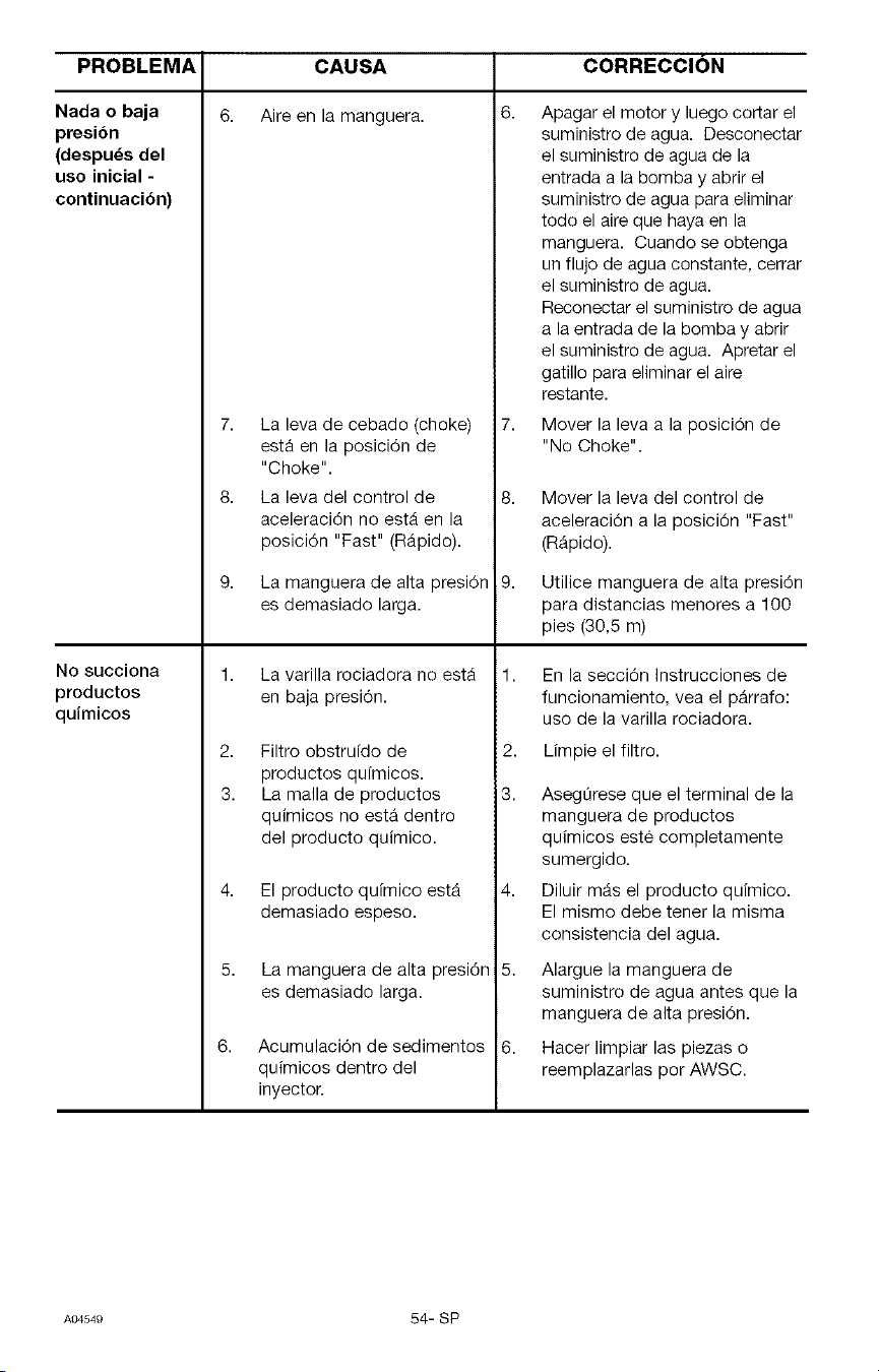
PROBLEMA CORRECCION
6.
Nada o baja
presibn
(despu_s del
uso inicial -
continuacibn)
No succiona
productos
quimicos
CAUSA
Aire en la manguera.
7. La leva de cebado (choke)
estA en la posicidn de
"Choke".
8. La leva del control de
aceleraci6n no estA en la
posicidn "Fast" (RApido).
La manguera de alta presidn
es demasiado larga.
La varilla rociadora no estA
en baja presidn.
2. Filtro obstrufdo de
productos qufmicos.
3. La malla de productos
quimicos no estA dentro
del producto quimico.
6,
El producto quimico estA
demasiado espeso.
La manguera de alta presi6n
es demasiado larga.
Acumulaci6n de sedimentos
quimicos dentro del
inyector.
Apagar el motor y luego cortar el
suministro de agua. Desconectar
el suministro de agua de la
entrada a la bombay abrir el
suministro de agua para eliminar
todo el aire que haya en la
manguera. Cuando se obtenga
un flujo de agua constante, cerrar
el suministro de agua.
Reconectar el suministro de agua
a la entrada de la bombay abrir
el suministro de agua. Apretar el
gatillo para eliminar el aire
restante.
Mover la leva a la posici6n de
"No Choke".
Mover la leva del control de
aceleraci6n a la posici6n "Fast"
(RApido).
Utilice manguera de alta presi6n
para distancias menores a 100
pies (30,5 m)
En la secci6n Instrucciones de
funcionamiento, vea el pArrafo:
uso de la varilla rociadora.
Limpie el filtro.
2,
3. Asegt_rese que el terminal de la
manguera de productos
quimicos este completamente
sumergido.
4. Diluir mAs el producto quimico.
El mismo debe tener la misma
consistencia del agua.
5. Alargue la manguera de
suministro de agua antes que la
manguera de alta presi6n.
6. Hacer limpiar las piezas o
reemplazarlas por AWSC.
A04549 54- SP
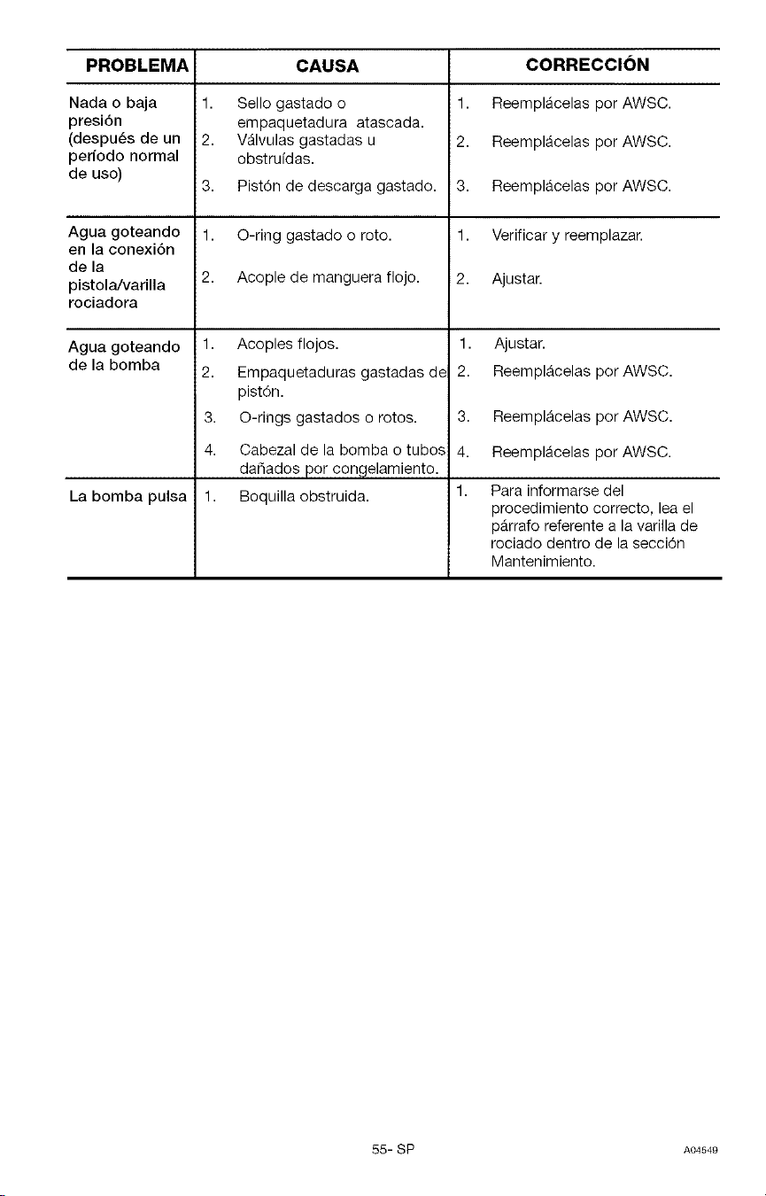
PROBLEMA CAUSA
Nada o baja
presi6n
(despues de un
periodo normal
de uso)
Agua goteando
en la conexi6n
de la
pistola/varilla
rociadora
Agua goteando
de la bomba
La bomba pulsa
1. Sello gastado o
empaquetadura atascada.
2. V_lvulas gastadas u
obstrufdas.
3. Pist6n de descarga gastado.
1. O-ring gastado o roto.
2. Acople de manguera flojo.
1. Acoples flojos.
2. Empaquetaduras gastadas dE
pist6n.
3. O-rings gastados o rotos.
CORRECCION
1. Reempl_celas por AWSC.
2. ReemplAcelas por AWSC.
3. ReemplAcelas por AWSC.
1. Verificar y reemplazar.
2. Ajustar.
1. Ajustar.
2. ReemplAcelas por AWSC.
4. Cabezal de la bomba o tubos
dadados por congelamiento.
1. Boquilla obstruida.
3. ReemplAcelas por AWSC.
4. ReemplAcelas por AWSC.
Para informarse del
procedimiento correcto, lea el
pArrafo referente a la varilla de
rociado dentro de la secci6n
Mantenimiento.
55- SP A04549
Your Home
For repair - in your home - of all major brand appliances,
lawn and garden equipment, or heating and cooling systems,
no matter who made it, no matter who sold it!
iiiiiiiiiiiiiii iiiiiiiiiiiiiiii
For the replacement parts, accessories and
owner's manuals that you need to do-it-yourself.
iiiiiiiiiiiiiii iiiiiiiiiiiiiiii
For Sears professional installation of home appliances
and items like garage door openers and water heaters.
1-800-4-MY-HOME ® Anytime, day or night
(1-800-469-4663) (U.S.A. and Canada)
www.,ea,s.oomwww.soa,s.o°
HHHHHHHi HHHHHHH_
HHHHHHHi HHHHHHH_
iiiiiiiiiiiiiii iiiiiiiiiiiiiiii
Our Home
iiiiiiiiiiiiiii iiiiiiiiiiiiiiii
For repair of carry-in products like vacuums, lawn equipment,
and electronics, call or go on-line for the nearest
Sears Parts and Repair Center.
iiiiiiiiiiiiiii iiiiiiiiiiiiiiii
1-800-488-1222 Anytime,dayornight(USA only)
iiiiiiiiiiiiii_ iiiiiiiiiiiiiiii
HHHHHHH_ HHHHHHH_
HHHHHHH_ HHHHHHH_
HHHHHHH_ HHHHHHH_
To purchase a protectionagreement (U.S.A.)
or maintenance agreement (Canada)on a product serviced by Sears:
1-800-827-6665 (U.S.A.) 1-800-361-6665 (Canada)
HHHHHHH_ HHHHHHH_
HHHHHHH_ HHHHHHH_
HHHHHHH_ HHHHHHH_
HHHHHHH_ HHHHHHH_
Parapedirserviciodereparaci6n Au Canada pourserviceen fran_ais:
adomicilio,y pardordenarpiezas: I_800.LE.FOYERMC
1-888-SU-HOGARsM 1-800-533-6937
www.sears.ca
© Sears, Roebuck and Co.
® Registered Trademark / TM Trademark / SM Service Mark of Sears, Roebuck and Co.
® Marca Registrada / TM Marca de Fabrica / SM Marca de Servicio de Sears, Roebuck and Co.
MC Marque de commerce / MD Marque d_pos_e de Sears, Roebuck and Co.