
41812.00892
Universal Wireless Wall Console Instructions
06/2021
WARNING
!
AVERTISSEMENT
UNE PORTE EN MOUVEMENT PEUT CAUSER DE GRAVES
BLESSURES, VOIRE LA MORT.
•N’installez PAS le transmetteur à moins que l’appareil de sécurité
du dispositif de fermeture de porte ne fonctionne conformément
au manuel du dispositif de fermeture de porte.
•La console murale doit être montée à la vue de la porte, à au
moins 5 pieds au-dessus du sol et il ne doit y avoir aucune pièce
de porte en mouvement à proximité.
•Éloignez les gens de l’ouverture lorsque la porte est en
mouvement.
•NE permettez PAS aux enfants de jouer avec le transmetteur ou
le dispositif de fermeture de porte.
Si l’inversion de sécurité ne fonctionne pas correctement :
•Fermez la porte, puis déconnectez le dispositif d’ouverture à
l’aide de la poignée de dégagement manuel.
•N’utilisez PAS le transmetteur ni le dispositif de fermeture de
porte.
•Référez-vous aux manuels du propriétaire de la porte et de
l’ouvre-porte avant de tenter toute réparation.
!
FIG. A
For questions or troubleshooting,
contact Customer Care by website
chat (www.geniecompany.com) or
by phone at: 1-800-354-3643 for
assistance.
Scan the QR code for instructions,
video, or additional information
and links.
Open battery cover and remove battery
tab before programming.
LED Signals:
- LED Blue blink indicates NORMAL status
- LED Red blink indicates LOW BATTERY
- LEDs will vary during programming
It is recommended to complete programming before mounting wall console.
NOTE: During programming, the garage door opener will operate. Ensure that the
garage door opening is clear of personnel or any obstructions.
Chart A
Genie® and Intellicode® are registered trademarks of The Genie Company. All other listed names and trademarks
are the property of their respective owners.
THINGS TO KNOW BEFORE STARTING:
•For use only with garage door operators complying with UL 325, manufactured after 1993 with
working photo eyes installed.
•During programming, the garage door opener may operate. Ensure that the garage door
opening is clear of personnel or any obstructions.
•Do not press the LEARN button for longer than the noted 2-3 seconds as it could cause the
existing, operational remotes and keypads to no longer work.
•All DOOR buttons are factory set to Genie Intellicode® 1.
DIP switch models are noted with an asterisk* - please visit our website for instructions on these
models and for additional alternate programming instructions:
www.geniecompany.com/alt-programming-UWWC.pdf
Below are the brands and specications that this console is compatible with. Find the ID# in Chart
A below that references your specic opener specication. You will need this number during
programming. Refer to STEP 1 to nd the type and/or LEARN/PROGRAM button.
STEP 1 - FIND SPECIFICATIONS & LEARN BUTTON
1. Locate the brand and opener/receiver specications for your device by consulting the label on
the opener/receiver, the instruction manual, the current remote controls for the opener, or the
original manufacturer of the opener/receiver.
2. Find the LEARN/PROG button on your device - shape, color or name of this button could vary
by brand. For garage door openers, be sure to check under the light covers. For commercial or
gate openers, this button may be on the circuit board of the opener. In some cases, this button
could also be on an external receiver that is mounted on or nearby the product. Consult the
devices manual if needed.
PRGM
SET
RADIO
SIGNAL
LEARN
CODE
CODE
LEARN
Gate
Receivers
EXAMPLES:
*For Marantec® openers, reference operator manual to program remotes to the operator head.
STEP 2 - PROGRAMMING THE UNIVERSAL WIRELESS WALL CONSOLE
IMPORTANT: For ID#4 Chamberlain®/LiftMaster®/Craftsman® Yellow Learn Button - move
immediately to the proper section below. For all other ID#s, proceed to LEARN METHOD section.
IMPORTANT: Please visit www.geniecompany.com/alt-programming-UWWC.pdf to nd
additional instructions and programming methods such as how to program dip switch
technology and how to change blink rate patterns.
LEARN METHOD (RECOMMENDED PROGRAMMING)
Review Chart A to nd your specications and available programming options. Each button can
be programmed individually to operate up to 3 dierent brands of garage door openers and gate
receivers.
1. Remove activation tab from inside battery compartment.
2. Find and remember the required number of button presses (ID#) in the LEARN METHOD
column next to your brands/specication in Chart A.
REMEMBER: For ID#4 Chamberlain®/LiftMaster®/Craftsman® Yellow Learn Button ONLY - move
immediately to instructions below. For all other ID#s, proceed to step 3.
3. Press and hold down the DELAY button until ALL 3 BLUE LEDs start blinking and then release
(@5 sec.)
4. Press the DOOR button of your choice the required number of times from Step 1 (Chart A).
TIP: You may program all 3 DOOR buttons at one time if preferred. The DELAY button press will signal
completion for all buttons.
5. Press the DELAY button one time to signal the entry is complete.
6. On the opener, press the LEARN/PROGRAM button for 2-3 seconds then release.
7. Press the DOOR button you just programmed once every two seconds until the opener
operates.
8. When the door stops moving, press the DOOR button again to test. Programming is
complete.
ONLY for ID#4 Chamberlain®/LiftMaster®/Craftsman® Yellow Learn:
1. Remove activation tab from inside battery compartment
2. Press and hold down the DELAY button until ALL 3 BLUE LEDs start blinking and then release
(@5 sec.)
3. Press the DOOR button of your choice four times.
TIP: You may program all 3 DOOR buttons at one time if preferred. The DELAY button press will signal
completion for all buttons.
4. Press the DELAY button one time to signal the entry is complete.
5. Press and hold down the DOOR button you just chose until the red LED in the top button
blinks and goes out (@5 sec.)
6. On the opener, press the LEARN/PROGRAM button for 2-3 seconds then release.
7. Press the door button you chose ONE time. Opener will click.
8. On the opener, press the LEARN/PROGRAM button again for 2-3 seconds then release.
9. Press the door button you chose ONE time again. Opener will click again.
10. Press the DOOR button again and the opener will activate.
11. When the door stops moving, press the DOOR button again to test. Programming is complete.
FCC Part 15.21 Statement:
Changes or modications not expressly approved by the party responsible for compliance could void the user’s authority to operate
the equipment.
FCC / IC Statement:
This device complies with FCC Part 15 and Industry Canada licence-exempt RSS standard(s). Operation is subject to the following two
conditions: (1) this device may not cause harmful interference, and (2) this device must accept any interference received, including
interference that may cause undesired operation of the device.
Wall Consoles should be mounted at least 5 feet from oor in a convenient location within sight
of the garage door.
• Remove battery cover, battery activation tab and batteries.
Mounting to garage framing:
1. Mark and drill a 3/32” pilot hole for the slotted mount screw. See Fig-A.
2. Install included screw into pilot hole, leaving 1/8” gap between the screw head and wall.
3. Hook the slotted mount on back of Wall Console over the screw.
4. Mark and drill a 3/32” pilot hole for the screw under battery door.
5. Secure Wall Console to the wall. (Do not over-tighten).
6. Reinstall batteries and battery cover.
Mounting to drywall:
1. Drill 3/16” pilot hole for slotted mount drywall anchor. See Fig-A.
2. Lightly tap drywall anchor into hole with a hammer until ush with wall.
3. Install included screw into anchor, leaving 1/8” gap between the screw head and wall.
4. Hook the slotted mount on back of Wall Console over the screw.
5. Mark position of pilot hole for the drywall anchor under the battery door and remove wall
console.
6. Drill a 3/16” pilot hole for the drywall anchor under the battery door.
7. Lightly tap anchor into hole with a hammer until ush with wall.
8. Secure Wall Console to the wall. (Do not over-tighten).
9. Reinstall batteries and battery cover.
STEP 3 - MOUNTING THE WALL CONSOLE
For Patent Information: www.geniecompany.com/patents, ©2021, The Genie Company
Rear
Screw Slot
Delay
Button
Door
Buttons
Clearing out the wireless wall console:
1. Press and hold down both the top DOOR button and the bottom DOOR button at the same
time.
2. When LED on the middle DOOR button gives two long blinks and goes out - then release both
buttons (@ 5 seconds).
To initiate the DELAY feature on any DOOR button:
1. Press and release the DELAY button one time for 10 seconds, two times for 15 seconds, or
three times for a 20 second DELAY.
2. Press and release the DOOR button of your choice. Activation will be delayed by 10, 15 or 20
seconds.
NOTE: With this feature, an open door will delay on close. A closed door will delay on opening. Press
the same DOOR button again to cancel the activation.
STEP 4 - OPERATING THE WALL CONSOLE
NOTE: Safety sensor override operation will not work with this console.
Operating a Door:
1. Press and release the door button of your choice. The door will move up or
down.
MOVING DOOR CAN CAUSE SERIOUS INJURY OR DEATH.
• DO NOT install wall counsel unless the door operator’s safety
devices work as required by the door operator’s manual.
• Wall Console must be mounted in sight of door, at least 5 feet
above oor and clear of moving door parts.
• Keep Door in Sight at all times when door is moving.
• DO NOT allow children to play with the operator controls.
If safety reverse does not work properly:
• Close door then disconnect opener using the manual release
handle.
• DO NOT use transmitter or controls for door operator.
• Refer to Door and Door Opener Owner’s Manuals before
attempting any repairs.
NOTE: This will revert all buttons back to the factory setting of Genie Intellicode 1. For buttons that
have been programmed to a Genie Intellicode 1 unit, please refer to the operator instruction manual to
clear the powerhead.
Le présent appareil est conforme aux CNR d’Industrie Canada applicables aux appareils radio
exempts de licence. L’exploitation est autorisée aux deux conditions suivantes : (1) l’appareil
ne doit pas produire de brouillage, et (2) l’utilisateur de l’appareil doit accepter tout brouillage
radioélectrique subi, même si le brouillage est susceptible d’en compromettre le fonctionnement.
AVAILABLE PROGRAM METHOD
LEARN METHOD ID#
Brand Name Specication Notes
Number of
Button Presses (ID#)
Genie® 315/390 MHz, Intellicode® I, 1995-current 1
Overhead Door® 315/390 MHz, CodeDodger® I, 1995-current 1
Chamberlain®
LiftMaster®
CraftsMan®
Purple Learn Button, Security +®, 2006-2014, 315 MHz 2
Orange/Red Learn Button, Security +®, 1996-2005, 390 MHz 3
Yellow Learn Button, Security +2.0®, 2011-current, 390 MHz 4
Green Learn Button, Billion Code®, 1993-1995, 390 MHz 5
Genie® 315/390 MHz, Intellicode® II, 2010-2011 6
Overhead Door® 315/390 MHz, CodeDodger® II, 2010-2011 6
Sommer® 310 MHz, Rolling Code 7
Linear® 318 MHz, Mega Code® 8
Wayne Dalton® 372.5 MHz, Rolling Code, 1999-current 9
Ryobi® 372.5 MHz, Rolling Code 10
Guardian® 303 MHz, Fixed Learn Code 11
Xtreme® brand 303 MHz, Fixed Learn Code 11
Marantec® 315 MHz, Fixed Learn Code 12
FAAC® 433.92 MHz, Rolling Code 13
*Chamberlain® 390 MHz, 9 Switch/3 Position Dip Switch
*Stanley® 310 MHz, 10 Switch/2 position Dip Switch
*Genie® 390 MHz, 9 & 12 Switch/2 Position Dip Switch, 1993-1995
*Overhead Door®
390 MHz, 9 Switch/3 Position Dip Switch, 1993-1995
For these dip switch
instructions, visit
www.geniecompany.com*
*For instructions on these Dip Switch specications, visit:
www.geniecompany.com/documents/alt-programming-UWWC.pdf

Page1
ALTERNATEINSTRUCTIONS
UNIVERSALWIRELESSWALLCONSOLE
AlternateinstructionsforFixedCode/DipSwitchProgrammingandalternateblinkratesaretobe
usedinconjunctionwiththemaininstructionset.
ChangesmadetotheblueLEDblinkratepatternwillimpactbatterylife. Forbestbatterylife,seeBlinkRate
Mode3toturnLEDsoffcompletely.
BLUELEDBlinkRateMode1:FactoryDefaultSetting
(BlinkRate‐Onceevery3sec)
Withonly(1)AAAbatteryinstalled‐holddowntheTOPDOORbuttonwhile
simultaneouslyinstallingthesecondAAAbattery.ContinuetoholdtheTOPDOOR
buttonforatotalof10secondsuntiltheblueLEDsontheOTHER2BUTTONSblink3
timesinunison.
BLUELEDBlinkRateMode2
(FasterBlinkRate‐Onceevery2seconds)
Withonly(1)AAAbatteryinstalled‐holddowntheMIDDLEDOORbuttonwhile
simultaneouslyinstallingthesecondAAAbattery.ContinuetoholdtheMIDDLE
DOORbuttonforatotalof10secondsuntiltheblueLEDsontheOTHER2BUTTONS
blink3timesinunison.
BLUELEDBlinkRateMode3
(BlueLEDOFF‐MaximumBatteryLife)
Withonly(1)AAAbatteryinstalled‐holddowntheBOTTOMDOORbuttonwhile
simultaneouslyinstallingthesecondAAAbattery.ContinuetoholdtheBOTTOM
DOORbuttonforatotalof10secondsuntiltheblueLEDsontheOTHER2BUTTONS
blink3timesinunison.
Page1:ChangingBlinkRatePatterns
Page2:FixedCode/DipSwitchProgramming
ALTERNATEINSTRUCTIONS
CHANGINGBLINKRATEPATTERNS
Page2
ALTERNATEINSTRUCTIONS
DIPSWITCH/FIXEDCODEPROGRAMMING
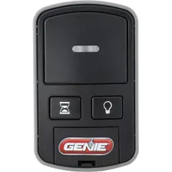
Iftheopenerhasagroupofswitcheswith3positionsperswitch(TRINARY):
SwitchintheUP(+)position=pressbutton1
SwitchintheMIDDLE(0)position=pressbutton2
SwitchintheDOWN(‐)position=pressbutton3
Inthisexample,thecodewouldbe:
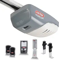
Iftheopenerhasagroupofswitcheswith2positionsperswitch(BINARY):
SwitchintheUP(+)position=pressbutton1
SwitchintheDOWN(‐)position=pressbutton3
Inthisexample,thecodewouldbe:
Step1:RecordSwitchPositions
Eachshadedboxbelowrepresentsaswitchposition.Intheseboxes,writeinthenumber1,2or3as
itcorrespondstothe+,0,or–switchpositionshownontheremote,openerorreceiver.Ifyouhave
lessthan12switches,onlyfillinwhatyouhave.YouwillreferencethissectioninSTEP3.5below.
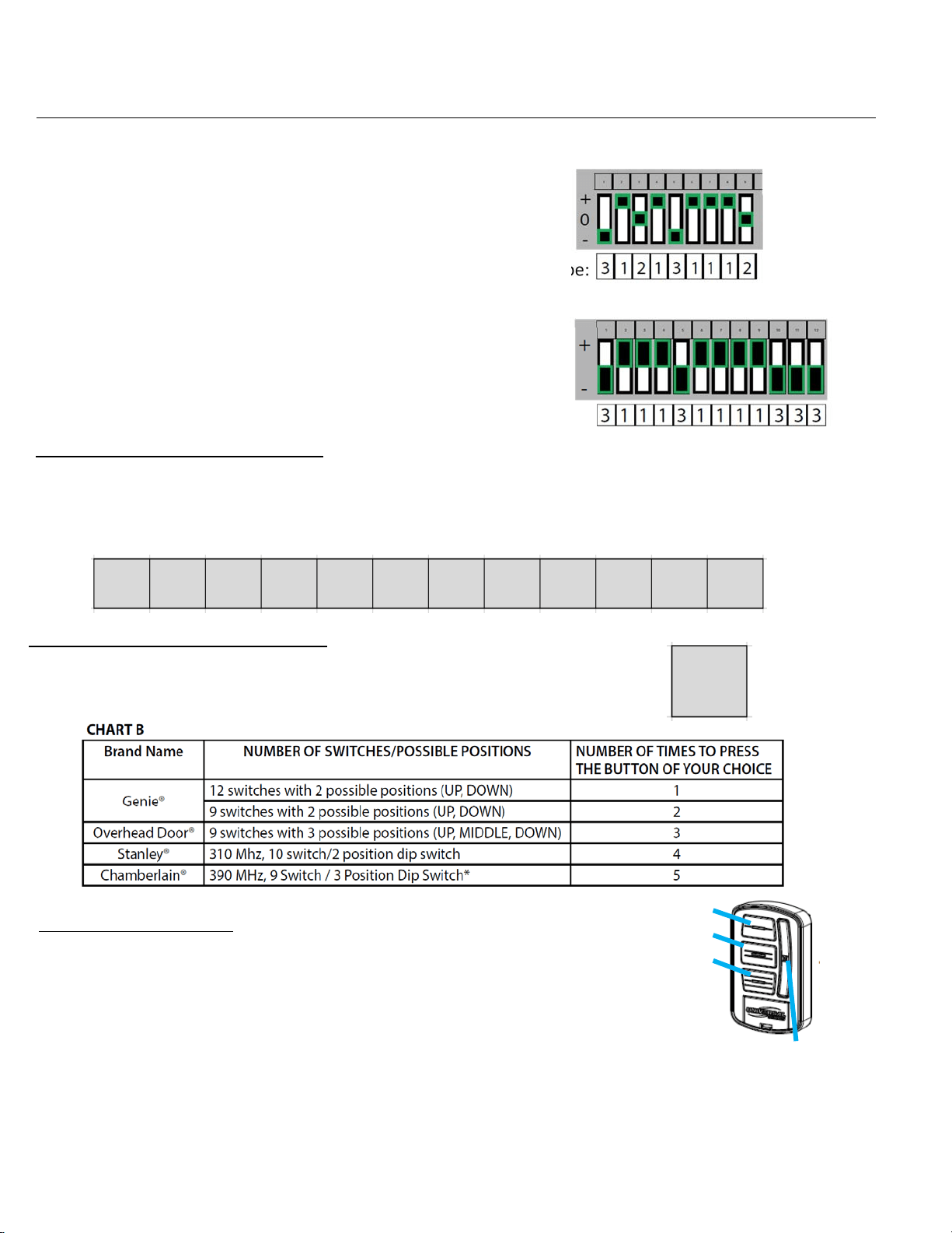
Step2:DetermineSpecifications
FindyourspecificationfromCHARTBbelowandrecordthenumberhere:
Thisboxshouldsa
y
1
,
2
,
3
,
4or5.YouwillreferencethisinSTEP3.3below.
Step3:Programming
1. Removeactivationtabfrominsidebatterycompartment.
2. PressandholddowntheDELAYbuttonfor@10secondsuntilonlyagreenLED
lightsonthetopbutton‐thenrelease.ThegreenLEDwillcontinueflashing.
3. PressyourDOORbuttonofchoicetherequirednumberoftimesthatcorresponds
withyouropenerfromChartBabove(recordedanswerfromSTEP2).
4. PresstheDELAYbuttononetimetosignaltheentryiscomplete.ThegreenLEDwillblinkrapidlyindicatingitis
readytoreceivetherecordedswitchpositionsfromSTEP1.
5. EntertheswitchpositionsthatyoudeterminedinSTEP1above(aseriesofDOORbuttonpresses–1,2or3).
6. Afteryouhaveenteredthefinalswitchposition,pressandreleasetheDELAYbuttonONEtimetosignalthe
entryiscomplete.
7. Testthebutton–thenextDOORbuttonpressshouldactivatetheopener.
DOORButtons:1
2
3
DELAYButton
FIGA