
Owner's Manual
ICRRFTSMRN°I
20.0 HP
ELECTRIC START
48" MOWER
AUTOMATIC
LAWN TRACTOR
Model No.
917.272240
• Safety
• Assembly
• Operation
• Maintenance
• Repair Parts
CAUTION:
Read and follow all
Safety Rules and Instructions
before operating this equip-
ment.
For answers to your questions
about this product, Call:
1-800-659-5917
Sears Craftsman Help Line
5 am - 5 pro, Mon- Sat
Sears, Roebuck and Co., Hoffman Estates, IL 60179
Visit our Craftsman website: www.sears.condcraftsman
Warranty ............................................... 2
Safety Rules ......................................... 3
Product Specifications .......................... 6
Assembly .............................................. 8
Operation ............................................ 12
Maintenance Schedule ...................... 18
Maintenance ....................................... 18
Service and Adjustments.................... 22
Storage ............................................... 29
Troubleshooting ................................. 30
Repair Parts........................................ 34
Parts Ordedng ..................... Back Cover
LIMITED TWo YEAR WARRANTY ON CRAFTSMAN RIDING EQUIPMENT PARTS
For two (2) years from the date of purchase, if this Craftsman Riding Equipment is
maintained, lubricated and tuned up according to the instructions in the owner's
manual, Sears will repair or replace, free of charge, any parts found to be defective in
material or workmanship. Warranty se_ice is available free of charge by returning
your Craftsman riding equipment to yoLa"nearest Sears Service Center. In-home
warranty service is available but a tdp charge will apply. This warranty applies only
while this product is in the United States.
This Warranty does not cover:
• Expendable items which become worn dudng normal use, such as blades, spark
plugs, air cleaners, belts and oil filters.
• Tire replacement or repair caused by punctures from outside objects, such as nails,
thorns, stumps,or glass.
• Repairs necessary because of operator abuse, includingbut not limited to, damage
caused by towing objects beyond the capability of the dding equipment, impacting
objects that bend the frame or crankshaft, or over speeding the engine.
• Repairs necessary because of operator negligence, including but not limitedto,
electrical and mechanical damage caused by improper storage, failure to use the
proper grade and amount of engine oil, failure to keep the deck clear offlammable
debds, or the failure to maintain the equipment according to the instructions
contained in the owner's manual.
• Engine (fuel system) cleaning or repairscaused by fuel determined to be contami-
nated or oxidized (stale). In general, fuel should be used within thirty(30) days of its
pumhase date.
• Riding equipment used for commercial or rental purposes. A product is =usedfor
commercial purpose" if is used for any purpose other than single family household
dwellings or in usage where profit is made.
LIMITED 90 DAY WARRANTY ON BATTERY
For ninety (90) days from date of purchase, if any battery included with this dding
equipment proves defective in matedal or workmanship and our testing determines
the battery will not hold a charge, Sears will replace the battery at no charge. War-
ranty service is available free of charge by returning your Craftsman dding equipment
to your nearest Sears Service Center. In-home warranty service is available but a trip
charge will apply. This warranty applies only while this product is in the United States.
TO LOCATE THE NEAREST SEARS SERVICE CENTER OR TO SCHEDULE IN-
HOME WARRANTY SERVICE, SIMPLY CONTACT SEARS AT 1-800-4-MY-HOME
This Warranty gives you specific legal rights, and you may also have other dghts
which may vary from state to state.
Seam, Roebuck and Co., D/817 WA, Hoffman Estates, IL 60179
IMPORTANT:Thiscuttingmachineiscapableofamputatinghandsand feet and
throwingobjects, Failure to observe the following safety instructionscould result in
serious injury or death.
I.GENERAL OPERATION
• Read, understand, and follow all
instructionsin the manual and on the
machine beforestarting.
• Only allow responsibleadults, who are
familiar with the instructions,to operate
the machine.
• Clear the area of objects suchas rocks,
toys, Wire,etc., which couldbe picked
up and thrown by the blade.
• Be sure the area is cleer ofother people
before mowing. Stop machine ifanyone
enters the area.
• Never carry passengers.
• Do notmow in reverseunless absolutely
necessary. Always lookdown and
behind before and while backing.
• Be aware of the mower discharge
directionand do notpointitat anyone.
Do not operate the mower withouteither
the entiregrasscatcher or the guardin
place.
• Slow down before turning.
• Never leave a running machine
unattended. Always turnoff blades, set
perking brake, stopengine, and remove
keys before dismounting.
• Turn off blades when notmowing.
• Stop engine before removinggrass
catcheror uncloggingchute.
• Mow only in daylightor good artificial
light.
• 0o not operate the machine while under
the influenceof alcoholor drugs.
• Watch for trafilcwhen operatingnear or
crossing roadways.
• Use extra care when loading or unload-
ingthe machine intoa trailer or truck.
• Data indicatesthat operators, age 60
years and above, are involved in a large
percentage of riding mower#elated
injuries. These operators should
evaluate their ability to operate the riding
mower safely enough to protect them-
salves and othersfrom serious injury.
• Keep machine free of grass, leaves or
other debris build-up which can touch
hot exhaust / engine parts and bum, Do
not allow the mower deck to plow leaves
or other debris which can cause build-
up to occur. Clean any oil orfuel
spillage before operating or storingthe
machine. Allow machineto cool before
storage.
II. SLOPE OPERATION
SIopee are a ma_orfactor related to toss--of-
controland tipover accidents,which can re-
suil in severe Injury or death. All slopes
require extra caution. Ifyou cannotback up
the slope or if you feel uneasy on it, do not
mow it.
DO:
• Mow up and down dopes, not across.
• Remove obstaclessuchas rocks,tree
limbs,etc.
Watch for holes, ruts,orbumps. Uneven
terraincould overturn the machine. Ta//
grass can hide obstac/es.
Use slowspeed. Choose a low gear so
that you willnothave tostopor shift
while on the slope.
Follow the manufacturer's recommenda-
tionsfor wheel weightsor counter-
weights to improvestability.
Use extra care withgrass catchersor
other attachments. These can change
the stabilityof the machine.
Keep all movement on the dopes stow
and gradual. Do not make sudden
changes in speed or direction.
Avoid sta_ng or stoppingon a slope. If
tires lose traction, disengage the blades
and proceed slowlystraightdown the
slope.
DO NOT:
• Do not turnon slopes unlessnecessary,
and then, turnslewiy and gradually
downhill,if possible.
• Do notmow near drepoffs, ditches,or
embankments. The mower coule
suddenly turnover If a wheal is over the
edge of a cliffor ditch,or ifan edge
caves _.
• DO notmow on wet grass.Reduced
tractioncould cause sliding.
• Oo net try to stabilizethe machiee by
putting your foot on the ground.
• Do notuse grass catcher on steep
slopes.
III.CHILDREN
Tragicaccidentscanoccuriftheoperator
isnotalerttothepresenceofchildren.
Childrenareoftenattractedtothe
reachine and the mowing activity. Never
assume that children will remain where
you last saw there.
• Keep children out of the mowing area
and under the watchful care of another
responsible adult.
• Be alert and turn machine off if children
enter the area.
• Before and when backing, look behind
and down for small children.
• Never carry children. They may fall off
and be seriously injured or interfere
with safe machine operation.
• Never allow children to operate the
machine.
• Use extra care when approaching blind
comers, shrubs, trees, or other objects
that may obscure vision.
IV. SERVICE
• Use extra care in handling gasoline
and other fuels. They are flammable
and vapors are explosive,
-Use only an approved container.
-Never remove gas cap or add fuel
with the engine running. Allow
engine to cool before refueling. Do
notsmoke.
-Never refuel the reachioe |ndenrs.
- Never store the machine or fuel
container inside where there is an
open flame, such as a water heater,
• Never run a machine inside a clo=
area.
• Keep nuts and bolts, especially bl
attachment bolts, tight and keep
equipment in good condition.
• Never tamper with safety devices.
Check their proper operation reg_
• Keep machine tree of grass, leave
other debds build-up. Clean oil or
spillage. Allow machine to cool b*
stodag.
• Stop and Inspect the equipment if
strike an object. Repair, if eecess=
before restarting.
• Never make adjustments or repair
with the engine running.
• Grass catcher components are sul
to wear, damage, and detedoratio_
which could expose moving parts
allow objects to be thrown. Frequ
check components and replace wi
manufacturer's recorereended par
when necessary.
• Mower blades are sharp and can
Wrap the blade(s) or wear gloves,
use extra caution when servicing
• Check brake operation frequently
Adjust and service as required.
• Be sure the area is clear of other
people before mowing. Stop machine if
anyone enters the area.
• Never carry passengers or children
even with the blades off.
• Do not mow in reverse unless abso-
lutely necessary. Always look down
and behind before and while backing.
• Never cam/children. They may fall off
and be seriously injured or interfere
with safe machine operation.
• Keep children out of the mowing area
and under the watchful care of another
responsible adult.
• Be alert and turn machine off if ch
enter the area.
• Before and when backing, lookb*
and dawn for sreall children.
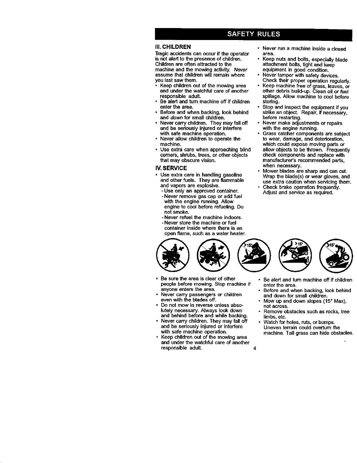
• Mow up and down slopes (15° Ms
notacross.
• Remove obstacles such as rocks,
limbs, etc.
• Watch for holes, ruts, or bumps.
Uneven terrain could overtum the
reachine. Tall grass can hide obsl

• Useslowspeed.Choosealowgearso
thatyouwillnothavetostoporshift
whileontheslope.
• Avoidstartingorstoppingonaslope.If
tireslosetraction,disengagethe
bladesandproceedslowlystraight
downtheslope.
• Ifmachinestopswhilegoinguphill,
disengageblades,shiftintoreverse
and back down slowly.
• Do not turn on slopes unless neces-
sary, and then, tum slowlyand gradu-
ally downhill, if possible.
_l_Look forthis symbolto pointout
important safety precautions. It means
CAUTIONIII BECOMEALERTIII YOUR
SAFETY IS INVOLVED.
_CAUTION: In order to prevent
accidental starting when setting up,
transporting, adjusting or making repairs,
always disconnect spark plug wire and
place wire where it cannot contact spark
plug.
_CAUTION: Do not coast down a hillin
neutral, you may lose controlof the
tractor.
_:_CAUTION: Tow onlythe attachments
that are recommandedby and comply
with specificationsof the manufacturer of
your tractor. Use common sense when
towing. Operate only at the lowest
possiblespeed when on a slope. Too
heavy of a load, while on a slope, is
dangerous. Tires can lose traction with
the ground and cause you to lose control
of your tractor.
_:_WARNING: Engine exhaust, some of
its constituents, and certain vehicle
components contain or emit chemicals
known to the State of Californiato cause
cancer and birthdefects or other repro-
ductive harm.
_:_WARNING: Battery pests, terminals
and related accessodes contain lead and
lead compounds, chemicals known to the
State of California to cause cancer and
birth defects or other reproductiveharm.
Wash hands after handling.
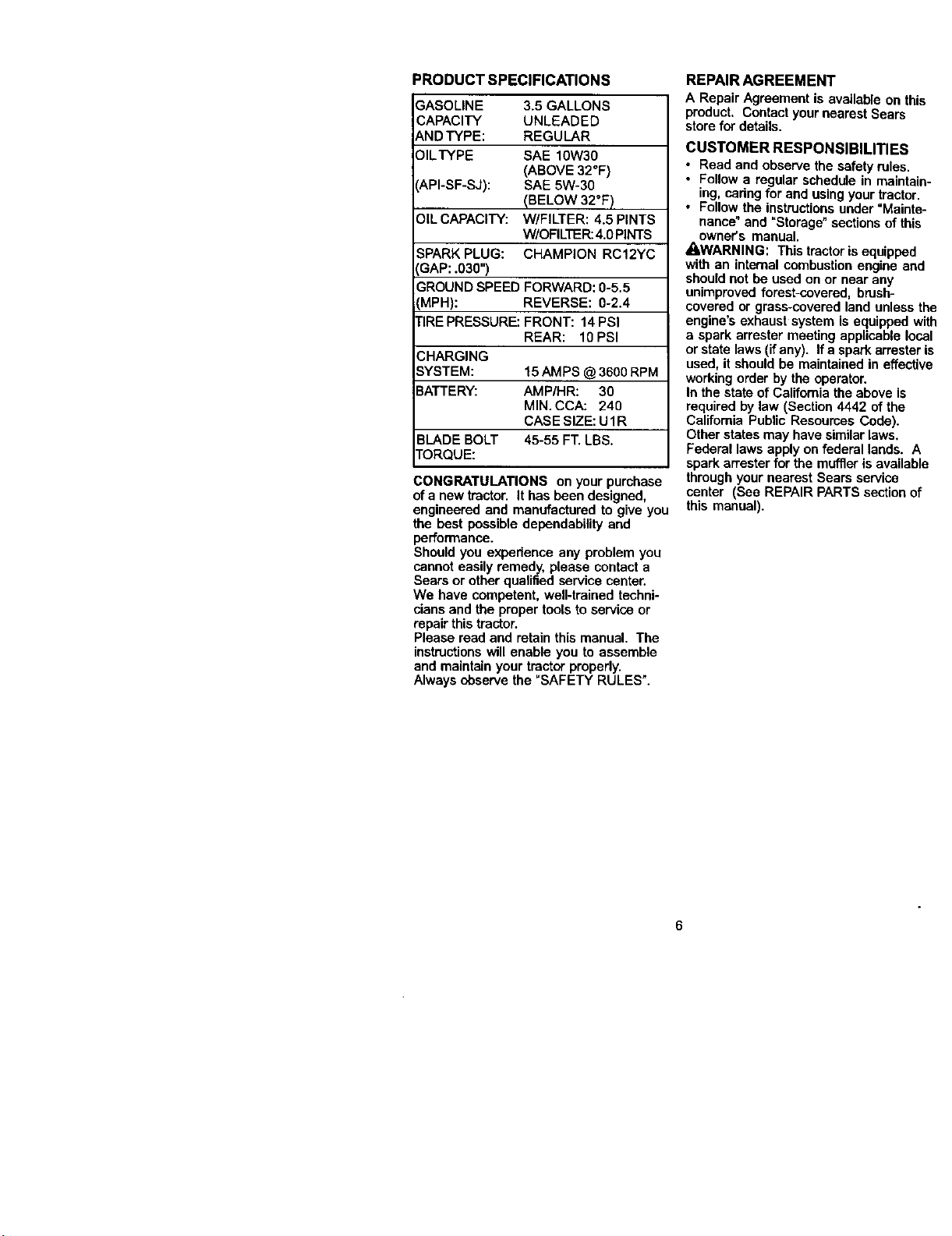
PRODUCT SPECIFICATIONS
3ASOLINE
CAPACITY
_,NDTYPE:
31LTYPE
API-SF-SJ):
91LCAPACITY:
3.5 GALLONS
UNLEADED
REGULAR
SAE 10W30
(ABOVE 32°F)
SAE 5W-30
(BELOW 32°F)
W/FILTER: 4.5 PINTS
W/OFILTER:4.0 PINTS
SPARK PLUG: CHAMPION RC12YC
3AP: .030")
GROUND SPEED FORWARD: 0-5.5
[MPH): REVERSE: 0-2.4
rlRE PRESSURE: FRONT: 14 PSI
REAR: 10 PSI
CHARGING
SYSTEM: 15 AMPS @ 3600 RPM
3A'R'ERY: AMP/HR: 30
MIN. CCA: 240
CASE SIZE: U1R
BLADE BOLT 45-55 FT. LBS.
FORQUE:
CONGRATULATIONS on your purchase
of a new tractor. It has been designed,
engineered and manufactured to give you
the best possible dependability and
performance.
Should you experience any problem you
cannot easily remedy, please contact a
Sears or other qualified service center.
We have competent, well-trained techni-
cians and the proper tools to service or
repair this tractor.
Please read end retain this manual. The
instructionswill enable you to assemble
end maintain your tractor properly,
Always observe the "SAFETY RULES".
REPAIR AGREEMENT
A Repair Agreement is available on this
product, Contact your nearest Sears
store for details.
CUSTOMER RESPONSIBILITIES
• Read and observe the safety roles.
• Follow a regular schedule in maintain-
ing, cadng for and using your tractor.
• Follow the instructionsunder "Mainte-
nance" and "Storage" sectionsof this
owner's manual.
_QI,WARNING: This tractoris equipped
with an internal combustionengine and
should not be used on or near any
unimproved forest-covered, brush-
covered or grass-covered land unless the
engine's exhaust system is equipped with
a spark arrester meeting applicable local
or state laws (ifany). If a spark arresteris
used, it should be maintained in effective
working order by the operator.
In the state of California the above is
required by law (Section 4442 of the
California Public Resources Code).
Other states may have similarlaws.
Federal laws apply on federal lands. A
spark an'ester for the muffleris available
through your nearest Sears service
center (See REPAIR PARTS sectionof
this manual).
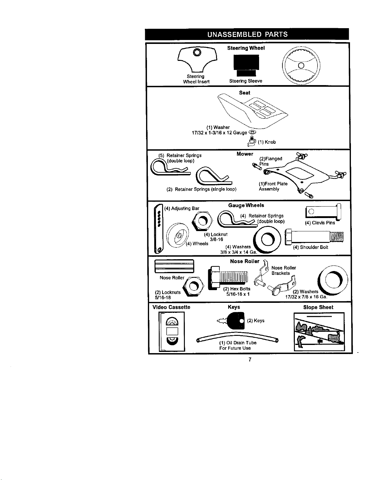
Steenng
Wheel Insert
Steering Wheel
Steering Sleeve
Seat
(1) Washer
17/32 x 1-3/16 x 12 Gauge _B)
_(1) Knob
(5) Retainer Spdngs
(2) Retainer Springs (single loop)
Mower (2)Flanged
(1)Front Plate _ "
(4) Adjusting Bar Gauge Wheels i(_ _
_--_ (4) Retainer Springs (_
LJ Y (doub,e,oop)
_,. _/(4) Wheels 14)Washers _%J_ L-] (4) Shoulder Bolt
3/5 x 3/4 x 14 Ga_""
I j Nose Roller_
_//0_ Nose Roller
_llt Brackets
Nose Rolle_ __ (_)
(2) Locknuts . s _ (2) Washers __.//
5116-18 5/16 18xl _ 17/32 x7/5 x 16 GaY
Video Cassette Keys
€ (2) Keys
Slope Sheet
Yournewtractorhasbeenassembledatthefactorywithexceptionofthosepartsleft
unassembledfor shipping purposes. To ensure safe and proper operation of your
tractor all parts and hardware you assemble must be tightened securely. Use the
correct tools as necessary to insure propertightness. Review the video cassette before
you begin.
TOOLS REQUIRED FOR ASSEMBLY
A socket wrench set will make assembly
easier. Standard wrench sizes you need
are listed below.
(1) 9/16" wrench (1) 314"Socket w/
(1) 112"wrench drive ratchet
(1) Utility knife (1) Pliers
(1) Tire pressure gauge
When dght or left hand ismentioned in
this manual, it means, from your pointof
view, when you are in the operating
position (seated behind the steering
wheel).
TO REMOVETRACTOR FROM
CARTON
UNPACK CARTON
1. Remove all accessible loose parts
and parts cartons from carton.
2. Cut, from top to bottom, along lines on
all four comers of carton, and lay
panels fiat.
3. Remove mower and packing materi-
als.
4. Check for any additional loose parts
or cartons and remove.
BEFORE REMOVING TRACTOR
FROM SKID
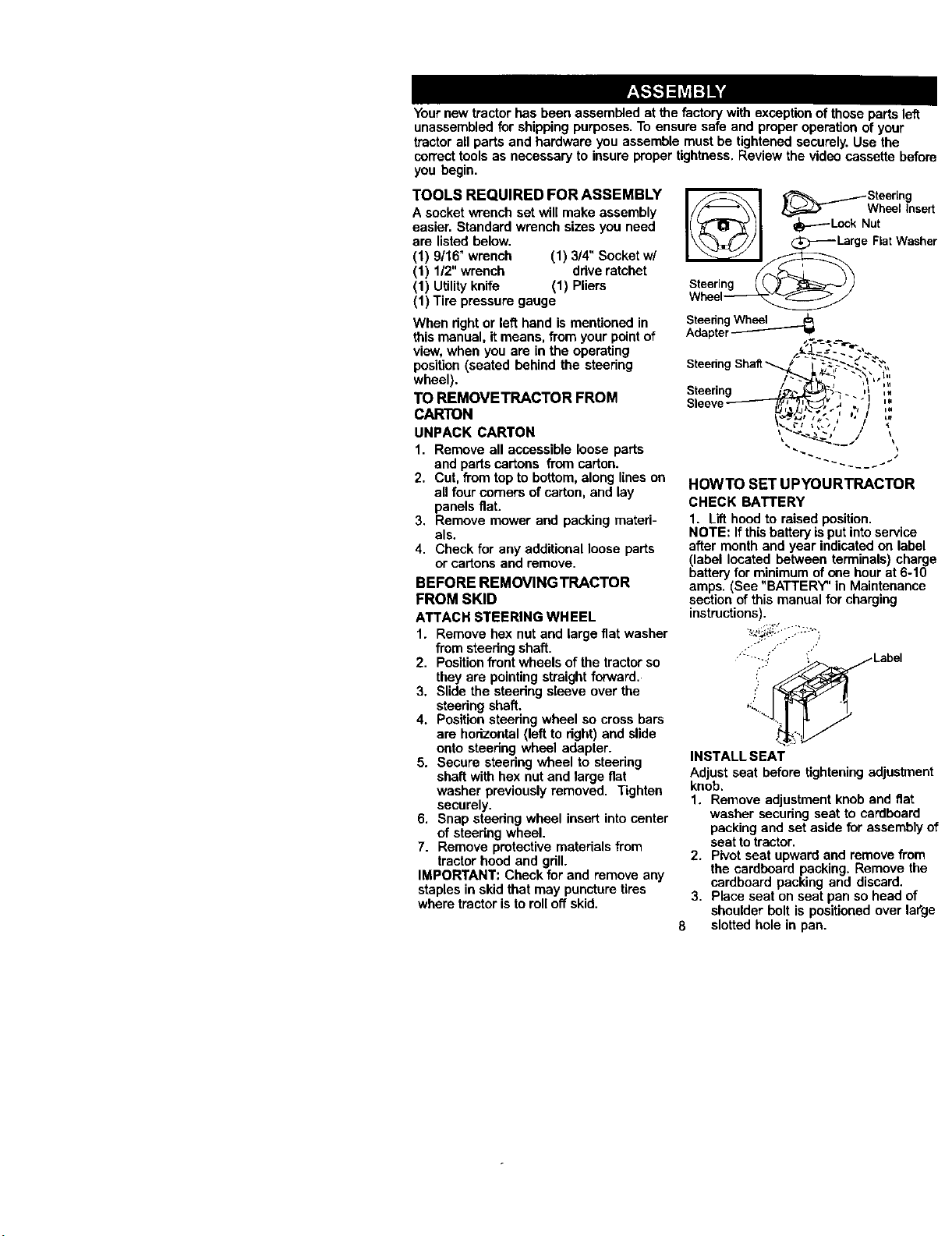
ATTACH STEERING WHEEL
1. Remove hex nut and large fiat washer
from steering shaft,
2, Positionfront wheels of the tractor so
they are pointingstraight forward.
3. Slide the steering sleeve over the
steering shaft.
4, Positionsteering wheel so cross bars
are horizontal (left to dght) and slide
onto steering wheel adapter.
5. Secure steering wheel to ateerieg
shaft with hex nut and large fiat
washer previously removed, Tighten
securely.
6. Snap steedng wheel insert into center
of steering wheel.
7. Remove protective materials from
tractor hood and grill.
IMPORTANT: Check for and remove any
staples in skid that may puncture tires
where tractor isto roll off skid,
_ ___--_-Steering
Wh linsert
I_ I_ge FiatWasher
Steering __ _/ _/
Wheel_
SteenngWheel ___
Adapter_
j:
SteeringShaft
Steering
.s _ i,a
);',---'I ',:
"" i I_ II _,f
-;' / I
HOWTO SET UPYOURTRACTOR
CHECK BATTERY
1. Lift hood to raised position.
NOTE: Ifthis battery isput intoservice
after monthand year indicated on label
blabellocated between terminals) charge
attery for minimum of one hour at 6-10
amps. (See "BATTERY' in Maintenance
section of this manual for charging
instructions).
'_., " ...----:,
Label
INSTALL SEAT
Adjust seat before tighteningadjustment
knob.
1. Remove adjustment knob and flat
washer securing seat to cardboard
packing and set aside for assembly of
seat to tractor.
2. Pivot seat upward and remove from
the cardboard packing, Remove the
cardboard packing and discard.
3, Place seat on seat pan so head of
shoulder bolt is positioned over large
6 slotted hole in pan.
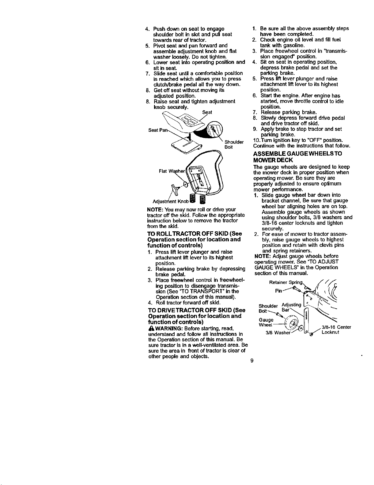
4. Push down on seat to engage
shoulder belt in slot and pull seat
towardsrear oftractor.
5. Pivot seat end pan forward and
assemble adjustment knob and fiat
washer loosely. Do not tighten.
6. Lower seat into operating position and
sit in seat.
7. Slide seat untila comfortable position
is reached which allows you to press
clutch/brake pedal all the way down.
8, Get off seat withoutmovingits
adjusted position.
8. Raise seat and tighten adjustment
knob securely.
Seat
Shoulder
Bo_t
NOTE: You may now rollor drive your
tractor off the skid. Follow the appropriate
instructionbelow to remove the tractor
fromthe skid.
TO ROLLTRACTOR OFF SKID (See
Operation section for location and
function of controls)
1. Press lift lever plunger end raise
attachment liftlever to its highest
position.
2. Release parking brake by depressing
brake pedal.
3. Place freewheel control in freewheel-
ing position to disengage transmis-
sion(See _TOTRANSPORT" in the
Operation section of this manual).
4. Roll tractorforward off skid.
TO DRIVETRACTOR OFF SKID (See
Operation section for location and
function of controls)
_WARNING: Beforestarting,read,
understand and follow all instructionsin
the Operation sectionof this manual. Be
sure tractoris in a well-ventilated area. Be
sure the area in front of tractor isclear of
other people and objects.
1. Be sure all the above assembly steps
have been completed.
2. Check engine oil level and fill fuel
tank with gasoline.
3. Place freewheel control in "transmis-
sion engaged" position.
4. Sit on seat in operating position,
depress brake pedal and set the
parking brake.
5. Press liftlever plunger and raise
attachment lift leverto its highest
position.
6. Start the engine. After engine has
started, move throttlecontrolto idle
position.
7. Release parking brake.
8. Slowly depress forward drive pedal
and drive tractor off skid.
9. Apply brake to stop tractorand set
parking brake.
10.Turn ignitionkey to "OFF" position.
Continue with the instructionsthat follow.
ASSEMBLE GAUGEWHEELSTO
MOWER DECK
The gauge wheels era designed to keep
the mower deck in proper position when
operatingmower. Be sure they are
propedy adjusted to ensure optimum
mower performance.
1. Slide gauge wheel bar down into
bracket channel, Be sure that gauge
wheel bar aligning holes ere on top.
Assemble gauge wheels as shown
using shoulder bolts, 3/8 washers and
3/8-16 center Iocknutsand tighten
securely.
2. For ease of mower to tractor assem-
bly, raise gauge wheels to highest
positionand retain with clevis pins
and spring retainers.
NOTE: Adjust gauge wheels before
operating mower. See =TOADJUST
GAUGE WHEELS" in the Operation
section of this manual.
RetainerSpring.. //_/r.
Shoulder A(_justing_K_" "_'_
Gauge _'/,'<_3 IL'!
Wheel 3/8-16 Center
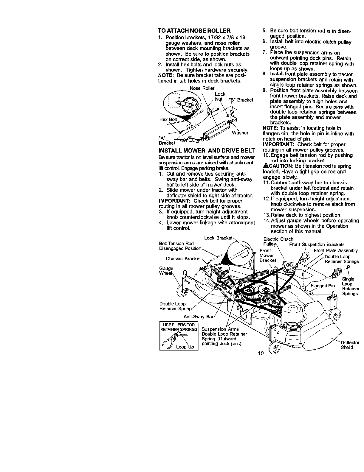
TOA'rrACHNOSEROLLER
1. Positionbrackets,17/32x7/8x16
gaugewashers,andnoseroller
betweendeckmounting brackets as
shown. Be sure to position brackets
on correct side, as shown.
2. Install hex boltsand lock nuts as
shown. Tighten hardware securely.
NOTE'. Be sure bracket tabs are posi-
tioned in tab holes in deck brackets.
Nose Roller
Lock
ut "B" Bracket
_sher
INSTALL MOWER AND DRIVE BELT
Be suretractorisoo levelsurfaceand mover
suspensionarms are raisedwithattachment
liftconlrel. Engage parking brake.
1. Cut and remove ties securing anti-
sway bar and belts. Swing anti-sway
bar to left side of mower deck.
2. Slide mower under tractor with
deflector shield to rightside of tractor.
IMPORTANT: Check belt for proper
routingin all mower pulley grooves.
3. If equipped, turn height adjustment
knob counterclockwise until it stops.
4. Lower mower linkage with attachment
liftcontrol•
Lock Bracket
Belt Tension Rod
Chassis Bracket,
Gauge
Wheel
Double Loop
Retainer Spring
Anti-Sway
USEPLIERSFOR
RETAINERSPRINGS Suspension Arms
Double Loop Retainer
Spring (Outward
Up pointing deck pins)
5. Be sure belt tension rodis in disen-
gaged position.
6. Install belt into electric clutch pulley
groove.
7. Place the suspension arms on
outward pointing deck pins. Retain
with double loop retainer spdng with
loops up as shown.
8. Install front plate assembly to tractor
suspension brackets and retain with
single loop retainer springs as shown.
9. Position front plate assembly between
front mower brackets, Raise deck and
plate assembly to align holes and
insert flanged pins. Secure pins with
double loop retainer spdngs between
the plate assembly and mower
brackets.
NOTE: Toassist in locating hole in
flanged pin, the hole in pin is inline with
notch on head of pin.
IMPORTANT: Check belt for proper
routing in all mower pulley grooves.
10.Engage belt tension rod by pushing
rod into locking bracket.
ACAUTION: Belt tension rod is spring
loaded. Have a tight grip on rod and
engage slowly.
11,Connect anti-sway bar to chassis
bracket under left footrest and retain
with double loop retainer spdng.
12.If equipped, turn height adjustment
knob clockwise to remove slack from
mower suspension.
13. Raise deck to highest position.
14.Adjust gauge wheels before operating
mower as shown in the Operation
section of this manual•
Electric Clutch
Pulley\ Front Suspention Brackets
Front \ Front Plate Assembly
Mower _ _DoubleLoop
Bracket Retainer Springs
Single
Loop
Retainer
Springs
10
CHECKTIRE PRESSURE
The tires on your tractor were ovednflated
at the factory for shipping purposes.
Correct tirepressure is importantfor best
cutting performance.
• Reduce tire pressure to PSI shown in
=PRODUCT SPECIFICATIONS" section
of this manual.
CHECK DECK LEVELNESS
For best cuttingresults, mower housing
should be propedy leveled. See =TO
LEVEL MOWER HOUSING" in the
Service and Adjustments section of this
manual.
CHECK FOR PROPER POSITION OF
ALL BELTS
See the figures that are shown for
replacing motion and mower blade drive
belts in the Service and Adjustments
section ofthis manual. Verify that the
belts are routed correctly.
CHECK BRAKE SYSTEM
After you learn how to operate your
tractor,check tosee that the brake is
propedyadjusted. See "TO ADJUST
BRAKE" in the Service and Adjustments
section of this manual.
I/CHECKLIST
BEFOREYOU OPERATE AND ENJOY
YOUR NEW TRACTOR, WE WISH TO
ASSURE THATYOU RECEIVE THE BEST
PERFORMANCE AND SATISFACTION
FROM THIS QUALITY PRODUCT.
PLEASE REVIEWTHE FOLLOWING
CHECKLIST:
/' All assembly instructionshave been
completed.
,,/No remaining loose parts in carton.
#" Battery is properly prepared and
charged. (Minimum 1 hour at 6 amps).
•/ Seat is adjusted comfortably and
tightened securely.
/ All tires are properly inflated. (For
shipping purposes, the tires were
overinflated at the factory).
/" Be sure mower deck is properly leveled
side-to-sido/front-to-rear for best cutting
results. (Tires must be properly inflated
for leveling).
4" Check mower and drive belts. Be sure
they are routed propedy around pulleys
and inside all belt keepers.
/ Check wiring. See that all connections
are still secure and wires are properly
clamped.
/" Before driving tractor, be sure free-
wheel control is in drive position.
WHILE LEARNING HOWTO USEYOUR
TRACTOR, PAYEXTRA ATTENTION TO
THE FOLLOWING IMPORTANT ITEMS:
/ Engine oil is at proper level.
/' Fuel tank is filledwith fresh, clean,
regular unleaded gasoline.
,/Become familiar with all controls - their
location and function. Operate them
before you start the engine.
/ Be sure brake system is in safe
operating condition.
•/ It is importantto purge the transmission
before operating your tractor for the first
time. Follow proper starting and
transmission purging instructions (See
"TO START ENGINE" and "PURGE
TRANSMISSION" in the Operation
section of this manual).
11
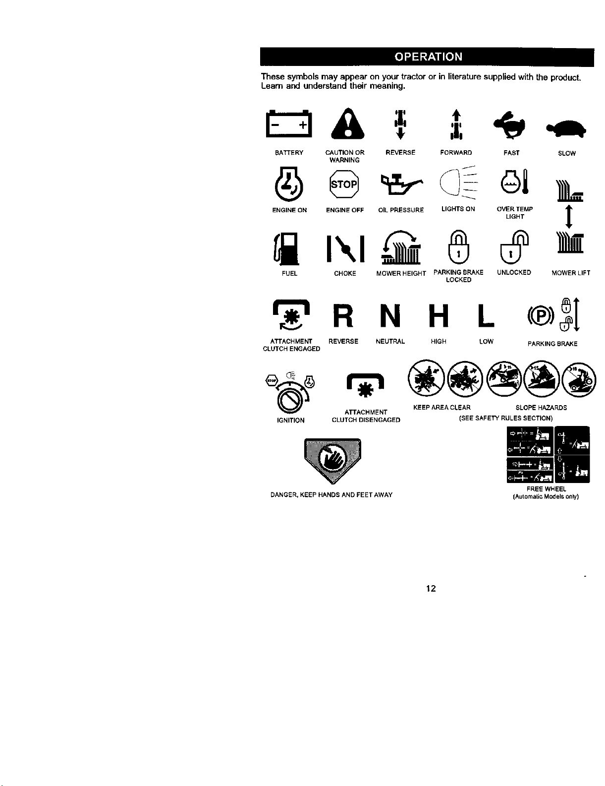
These symbols may appear on your tractor or in literature suppliedwith the product,
Learn and understand their meaning.
A =,
BATTERY CAUTION OR REVERSE FORWARD FAST SLOW
WARNING
ENGINE ON ENGINE OFF OIL PRESSURE LIGHTS ON OVER TEMP
LIGHT
FUEL CHOKE MOWER HEIGHT PARKING BRAKE UNLOCKED
LOCKED
!
MOWER LIFT
_r_RN H L
ATTACHMENT REVERSE NEUTRAL HIGH LOW
CLUTCH ENGAGED
®3I
PARKING BRAKE
e_(_ ATTACHMENT KEEP AREA CLEAR SLOPE HAZARDS
IGNITION CLUTCH DISENGAGED
DANGER, KEEP HANDS AND FEET AWAY
(SEE SAFETY RULES SECTION)
FREE WHEEL
(Automatic Modelsonly)
12
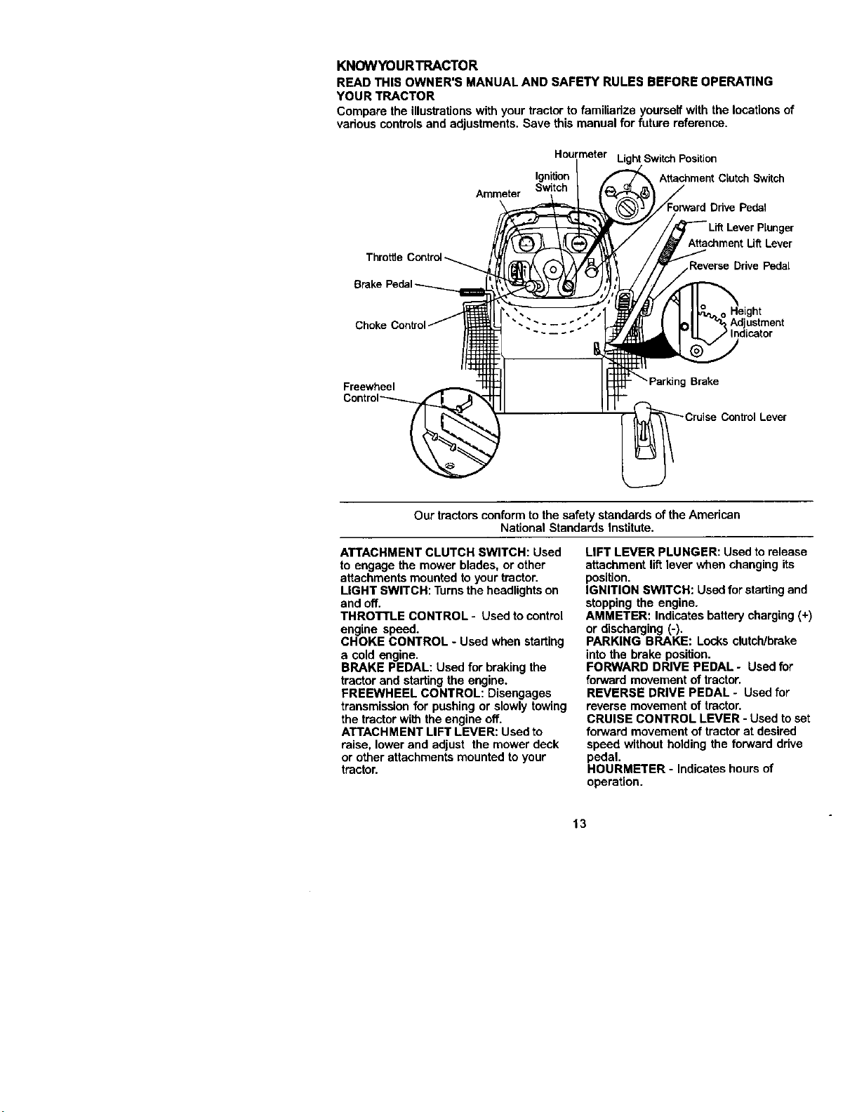
KNOWYOURTRACTOR
READTHISOWNER'SMANUALANDSAFETYRULESBEFOREOPERATING
YOURTRACTOR
Comparetheillustrationswithyourtractortofamiliarizeyourselfwiththelocationsof
variouscontrolsandadjustments.Savethismanualforfuturereference.
Brak
Ammeter
Hourmeter Light Switch Position
Ignition Attachment Clutch Switch
Pedal
Plunger
Attachment Ult Lever
Reverse Drive Pedal
Chok Adjustment
Indicator
Freewheel
Brake
Lever
Our tractors conformto the safety standards of the American
National Standards Institute.
ATTACHMENT CLUTCH SWITCH: Used
to engage the mower blades, or other
attachments mounted to your tractor.
LIGHT SWITCH: Turnsthe headlights on
and off.
THROTTLE CONTROL - Used to control
engine speed.
CHOKE CONTROL - Used when starting
a cold engine.
BRAKE PEDAL: Used for braking the
tractor and starting the engine.
FREEWHEEL CONTROL: Disengages
transmissionfor pushing or slowly towing
the tractorwith the engine off.
ATTACHMENT LIFT LEVER: Used to
raise, lower and adjust the mower deck
or other attachments mounted toyour
tractor.
LIFT LEVER PLUNGER: Used to release
attachment lift lever when changing its
position.
IGNITION SWITCH: Used for startingand
stopping the engine.
AMMETER: Indicates batterycharging (+)
or discharging (-).
PARKING BRAKE: Locks clutch/breke
into the brake position.
FORWARD DRIVE PEDAL - Usedfor
forward movement of tractor.
REVERSE DRIVE PEDAL - Used for
reverse movement of tractor.
CRUISE CONTROL LEVER - Used to set
forward movement of tractor at desired
speed without holding the forward drive
pedal.
HOURMETER - Indicates hours of
operation.
13
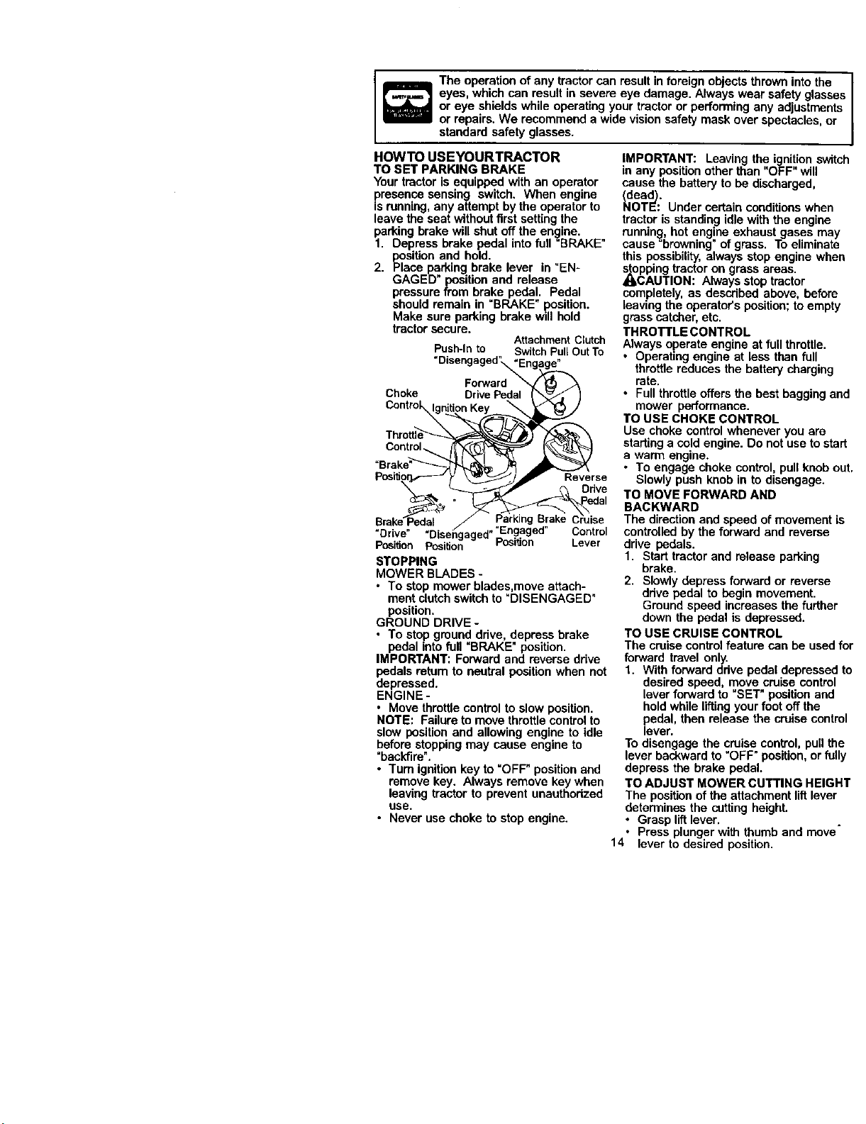
Theoperationofanytractorcanresultinforeign objects thrown into the /
eyes, which can result in severe eye damage. Always wear safety glasses
1
or eye shields while operating your tractor or performing any ad ustments
or repairs. We recommend a w de v s on safety mask over spectacles, or
standard safety glasses.
HOWTO USEYOURTRACTOR
TO SET PARKING BRAKE
Your tractor is equipped with an operator
presen.ce sensing switch. When engine
Is running, any attempt by the operator to
leave the seat withoutfirst setting the
parking brake will shut off the engine.
1. Depress brake pedal into full "BRAKE _
position and hold.
2. Place parking brake lever in "EN-
GAGED" position and release
pressure from brake pedal. Pedal
should remain in "BRAKE" position.
Make sure parking brake will hold
tractor secure.
AttachmentClutch
Push-Into SwitchPullOutTo
"Disengaged_,_En le.
Throttle_,_( _.
o ° al
= rive" Disengaged ..
Position PGsition PosdJon Lever
STOPPING
MOWER BLADES -
• To stop mower blades,move attach-
ment clutchswitchto _DISENGAGED"
position,
GROUND DRIVE -
• To stop ground ddve, depress brake
pedal into full =BRAKE" position.
IMPORTANT: Forward and reverse drive
pedals retum to neutral position when not
depressed.
ENGINE -
• Move throttle control to slow position.
NOTE: Failure tomove throttle controlto
slow positionand allowing engine to idle
before stopping may cause engine to
_beckfire'.
• Turn ignitionkey to =OFF"position and
remove key. Always remove key when
leaving tractor to prevent unauthorized
use.
• Never use choke to stop engine.
IMPORTANT: Leaving the ignitionswitch
in any positionother than "OFF" will
cause the battery to be discharged,
: Under certain conditionswhen
tractor is standing idle with the engine
running, hot engine exhaust gases may
cause=browning" of grass. To eliminate
this possibility,always stop engine when
_Ocpping tractor on grass areas.
AUTION: Always stop tractor
completely, as described above, before
leaving the operator's position;to empty
grass catcher, etc.
THROTTLE CONTROL
Always operate engine at full throttle.
• Operating engine at less than full
throttle reduces the battery charging
rate.
• Full throttleoffers the best bagging and
mower performance.
TO USE CHOKE CONTROL
Use choke control whenever you ere
starting a cold engine. Do not use to start
a warm engine.
• To engage choke control, pull knob out.
Slowly push knob in to disengage.
TO MOVE FORWARD AND
BACKWARD
The directionand speed of movement is
controlled by the forward and reverse
drive pedals.
1. Start tractor and release parking
brake,
2. Slowlydepress forward or reverse
drive pedal to begin movement.
Ground speed increases the further
down the pedal is depressed.
TO USE CRUISE CONTROL
The cruise controlfeature can be used for
forward travel only.
1. With forward drive pedal depressed to
desired speed, move cruise control
lever forward to "SET" position and
hold while liftingyourfoot off the
pedal, then release the cruise control
lever.
To disengage the cruise control, pull the
lever backward to "OFF" position, or fully
depress the brake pedal.
TO ADJUST MOWER CUTTING HEIGHT
The positionof the attachment liftlever
determines the cutting height.
• Grasp liftlever.
• Press plunger with thumb and move
14 lever to desired position.
Thecuttingheightrangeisapproxi-
mately1-1/2to4".Theheightsare
measuredfrom the ground to the blade
tip with the engine not running. These
heightsare approximate and may vary
depending upon soil conditions,height of
grass andtypes of grass being mowed.
The average lawn should be cut to
approximately 2-1/2 inches during the
coolseason and to over 3 inches
dudnghot months. For healthier and
better looking lawns, mow often and
after moderate growth.
• For best cutting performance, grass
over 6 inches in height should be
mowed twice. Make the firstcut
relatively high; the second to desired
height.
TO ADJUST GAUGE WHEELS
Gauge wheels are propedy adjusted
when they are slightlyoff the ground
when mower is at the desired cutting
height in operating position. Gauge
wheels then keep the deck in proper
positionto help prevent scalpingin most
terrain conditions.
NOTE: Be sure tractoris ona fiat level
surface.
1. Lower mower and adjust mower to
desired cutting height.
2. Remove retainer springand clevis pin
which secure each gauge wheel bar.
3. Lower gauge wheels to ground. Raise
igaugewheels slightlyto align holes in
racket and gauge wheel bar and
insert clevis pin. Gauge wheels
should be slightly offthe ground.
4. Replace retainer spdng into clevis pin.
5. Be sure all gauge wheels are in the
same setting.
IMPORTANT: Be sure to readjust gauge
wheels if you change the cutting height
of the mower deck.
Retainer
Sprin!
Clevis Pin
TO OPERATE MOWER
Your tractor is equipped with an operator
presence sensing switch. Any attempt by
the operator to leave the seat with the
engine running and the attachment clutch
engaged will shut off the engine.
1. Select desired height of cut.
2. Start mower blades by engaging
attachment clutchcontrol.
15
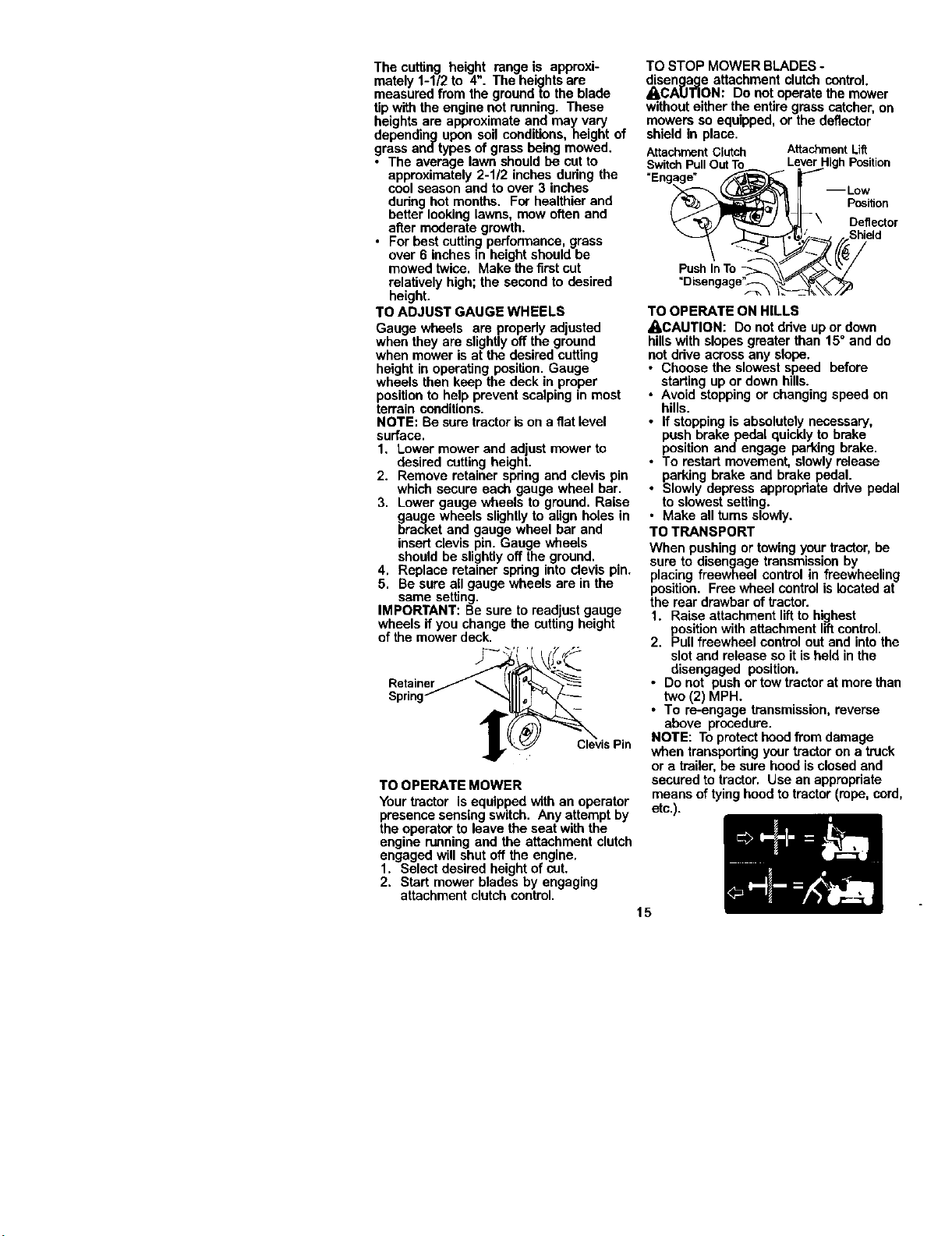
TO STOP MOWER BLADES -
disengage attachment clutch control
A,CA[J'I3ON: Do not operate the mower
withouteither the entire grass catcher,on
mowers so equipped, or the deflector
shield in place.
AttachmentClutch AttachmentLift
SwitchPullOutTo LeverI Position
Deflector
Push In To
=Disengage"_
TO OPERATE ON HILLS
_,CAUTION: Do not drive upor down
hills with slopes greater than 15° and do
not ddve acrossany slope.
• Choose the slowest speed before
starting up or down hills.
• Avoid stoppingor changing speed on
hills.
• If stopping isabsolutely necessary,
push brake pedal quicklyto brake
position and engage parking brake.
• To restart movement, slowly release
parking brake and brake pedal.
• Slowly depress appropriate ddve pedal
to slowest setting.
• Make all turns slowly.
TO TRANSPORT
When pushing or towing yourtractor,be
sure to disengage transmission by
placing freewheel control in freewheeling
position. Free wheel controlis located at
the rear drawbar oftractor.
1. Raise attachment liftto highest
positionwith attachment liftcontrol.
2. Pull freewheel control out and intothe
slot and release so it is held in the
disengaged position.
• Do not push or tow tractorat more than
two (2) MPH.
• To re-engage transmission,reverse
above procedure.
NOTE: Toprotect hoodfrom damage
when transportingyour tractor on a truck
or a trailer, be sure hood is closed and
secured to tractor. Use an appropriate
means of tying hoodto tractor (rope, cord,
etc.).
TOWINGCARTSANDOTHERATTACH-
MENTS
Towonlytheattachmentsthatare
recommendedbyendcomplywith
specificationsofthemanufacturerofyour
tractor.Usecommonsensewhentowing.
Toeheavyofaloud,whileonaslope,is
dangerous.Tirescanlosetractionwith
thegroundendcauseyoutolosecontrol
ofyourtractor.
BEFORESTARTINGTHEENGINE
CHECKENGINEOILLEVEL
Theengineinyourtractorhasbeen
shipped,fromthefactory,alreadyfilled
withsummerweightoil.
1. Checkengineoilwithtractoronlevel
ground.
2. Unthreadandremoveoilfill cap/
dipstick;wipe oil off. Reinsert the
dipstickinto the tube and rest oil fill
cap on the tube. Do not thread the
cap onto the tube. Remove and read
oil level. If necessary, add oil until
=FULL" mark on dipstick is reached.
Do not overfill.
• For cold weather operation you should
change oilfor easier starting (See "OIL
VISCOSITY CHART" inthe Mainte-
nance sectionof this manual).
• To change engine oil, see the Mainte-
nance section in this manual.
ADD GASOLINE
• Fillfuel tank. Use fresh, clean, regular
unleaded gasoline with a minimum of
87 octane. (Use of leaded gasoline will
increase carbon and lead oxide
deposits and reduce valve life). De not
mix oil with gasoline. Purchase fuel in
quantities that can be used within 30
days to assure fuel freshness.
IMPORTANT: When operating in tem-
peratures below 320F(0°C), use fresh,
clean winter grade gasoline to help
insure good cold weather starting.
•,WARNING: Experience indicates that
alcohol blended fuels (called gasehol or
using ethanol or methanol) can attract
moisture which leads to separation and
formation of acids during storage. Acidic
gas can damage the fuel system of an
engine while in storage. To avoid engine
problems, the fuel system should be
emptied before storage of 30 days or
longer. Drain the gas tank, start the
engine and let it run untilthe fuel lines
and carburetor are empty. Use fresh fuel
next season. See Storage Instructionsfor
additional information. Never use engine
or carburetor cleaner products in the fuel
tank or permanent damage may occur.
_CAUTION: Fillto bottom ofgas tank
fillerneck. Do not overfill.Wipe off any
spilled oil or fuel. Do notstore, spill or use
gasoline near an open flame,
TO START ENGINE
When starting the engine for the first time
or if the engine has run out offuel, it will
take extra crankingtime to move fuel from
the tank to the engine.
1. Be sure freewheel controlis in the
transmission engaged position.
2. Sit on seat in operating position,
depress brake pedal and set parking
brake.
3. Move attachment clutchto "DISEN-
GAGED" position.
4. Move throttle control tofast position
5. Pullchoke controlout fora cold
engine start attempt. For a warm
engine start attempt the choke control
may not be needed.
NOTE: Before starting, read the warm and
cold starting procedures below.
6. Insert key intoignitionand turn key
clockwiseto =START" positionand
release key as soon as engine starts.
Do not run starter continuouslyfor
more than fifteen seconds per minute.
ifthe engine does not start after
several attempts, push choke control
in, wait a few minutes and tryagain. If
engine stilldoes net start, pull the
choke control outand retry.
WARM WEATHER STARTING (50° F and
above)
7. When engine starts, slowlypush
choke control in until the engine
begins to runsmoothly. If the engine
startsto run roughly,pullthe choke
controlout slightlyfor a few seconds
and then continue to push the control
in slowly.
• The attachments and ground drive can
now be used. If the engine does not
accept the load, restart the engine and
allow it to warm upfor one minute
using the choke as described above.
COLD WEATHER STARTING (50+ F and
below)
7. When engine starts, slowly push
choke control in untilthe engine
begins to run smoothly. CenUnueto
push the choke control in small steps
allowing the engine to accept small
changes in speed and load, untilthe
choke control isfully in. If the engine
starts to run roughly,pull the choke
control outslightlyfor a few seconds
and then contl'nueto push the control
in slowly.This may require an engine
warm-up pedod from several seconds
to several minutes, depending on the
16 temperature.
AUTOMATICTRANSMISSIONWARMUP
Beforedrivingtheunitincoldweather
thetransmssionshouldbewarmedupas
follows:
1. Be sure the tractoris on levelground.
2. Release the parkingbrake and let the
brake slowly retum to operating
position.
3. Allow one minute for transmissionto
warm up. This can be done during the
engine warm up period.
• The attachments can be used during
the engine warm-up period after the
transmissionhas been warmed up and
may require the choke control be
pulled out slightly.
NOTE: ff at a high altitude (above 3000
feet) or in cold temperatures (below 32 F)
the carburetorfuel mixture may need to
be adjustedfor best engine performance.
See TO ADJUST CARBURETOR" in the
Service and Adjustments section ofthis
manual.
PURGETRANSMISSION
_,CAUTION: Never engage or disengage
free.wheellever while the engine is
running.
To ensure proper operationand perfor-
manse, it is recommendedthatthe
transmissionbe purged before operating
tractorfor the firsttime.This procedurewill
removeany trapped air insidethe trans-
mission which may have developed during
shippingofyourtractor.
IMPORTANT: Should your transmission
requireremovalfor service or replacement,
it shouldbe purged after reinstallation
before operatingthe tractor.
1. Place tractor safely on level surface
with engine off and parking brake set.
2. Disengage transmission by placing
freewheel control in freewheeling
position(See =TO TRANSPORT" in
thissection of manual).
3. Sittingin the tractor seat, start engine,
After the engine is running, move
throttlecontrol to slow position.
Disengage parking brake.
4. Depress forward drive pedal to full
forward positionand holdfor five (5)
seconds and release pedal. Depress
reverse ddve pedal to full reverse
positionand hold for five (5) seconds
and release pedal. Repeat this
procedure three (3) times.
NOTE: Duringthisprocedurethere will be
no movementofdrivewheels. The air is
being removed from hydraulicdrive
system.
5. Shut- off engine and set parking
brake.
17
6. Engage transmissionby placing
freewheel control in drivingposition
(See "TO TRANSPORT in thissection
of manual).
7. Sitting in the tractor seat, start engine.
After the engine is running, move
throttlecontrol to haft (1/2) speed.
Disengage parking brake.
8. Drive tractor forward for approximately
five feet then backwardsfor five feet.
Repeat this drivingprocedure three
times.
Your tractor is now purged and now ready
for normal operation.
MOWlNGTIPS
• Mower should be propedy leveled for
best mowing performance. See "TO
LEVEL MOWER HOUSING" in the
Service and Adjustments section of this
manual.
• The left hand side of mower should be
used for trimming.
• Drive so that clippingsare discharged
onto the area that has been cut. Have
the cut area to the right of the tractor.
Thiswill resultin e more even distribu-
tion of clippingsand more uniform
cutting.
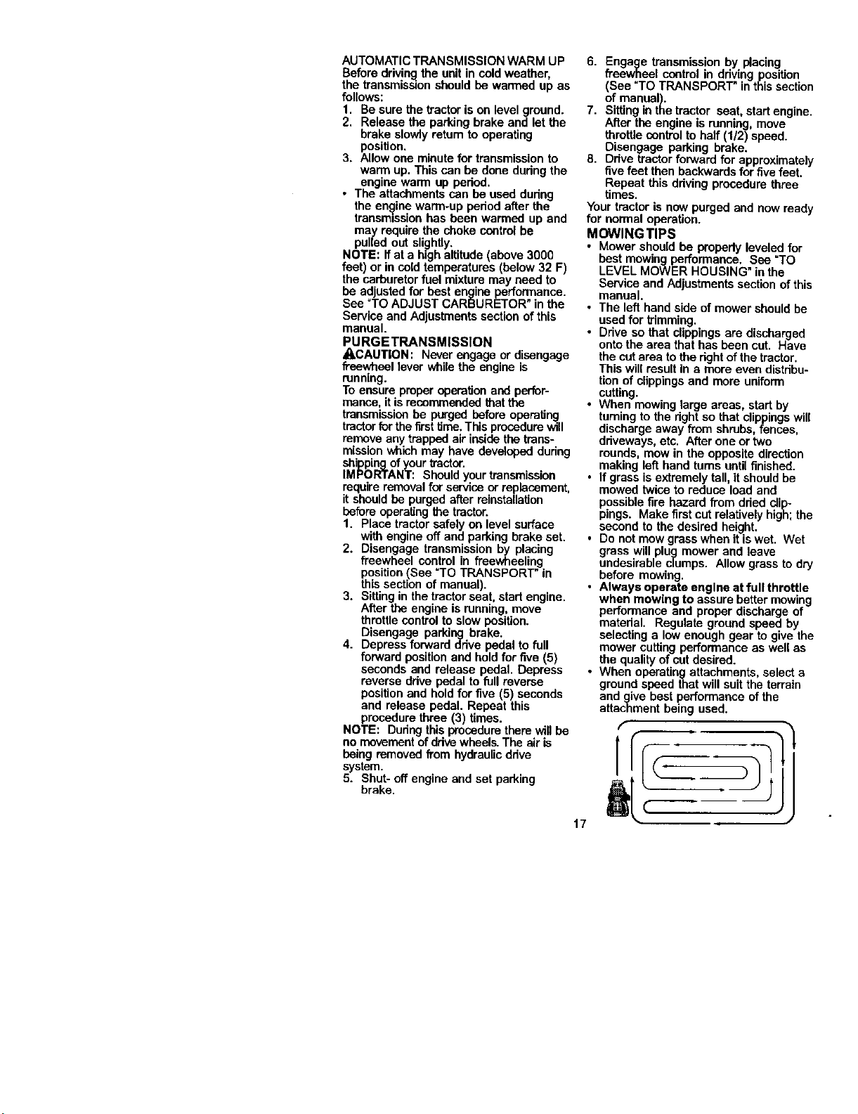
• When mowing large areas, start by
turningto the rightso that clippingswill
discharge away from shrubs, fences,
driveways, etc. After one or two
rounds, mow in the opposite direction
making left hand turns until finished.
• If grass is extremely tall, itshould be
mowed twice to reduce load and
possiblefire hazard from dried dip-
pings. Make first cut relativelyhigh;the
second to the desired height.
• Do not mow grass when it iswet. Wet
grass will plug mower and leave
undesirable clumps. Allow grass to dry
before mowing.
• Atways operate engine at full throttle
when mowing to assure better mowing
performance and proper discharge of
material. Regulate ground speed by
selecting e low enough gear to give the
mower cuttingperformance as well as
the qualityof cut desired.
• When operating attachments, select a
ground speed that will suit the terrain
and give best performance of the
attachment being used.
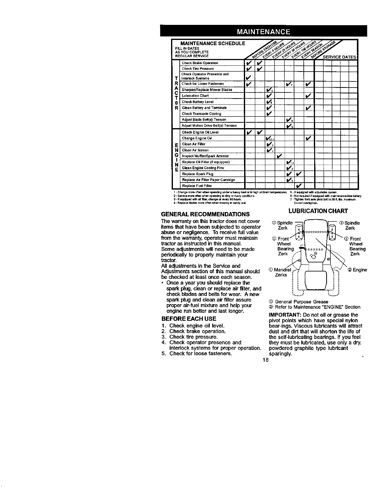
MAINTENANCESCHEDULE .,,,,_._/'_.__._',,_-_//,_,_//_'_'_/,'_/_/
CheckBrakeOpefat_oe 11## ip/
CheckTireP_essure _
Check Operator PreSence and
T Intedock SYStems 11_
R Check lot Lol_e Fasteners I_ ItS7
cA Sharpen/Replace Mowe_ Btades 1=/4
T Lul_ication Chad I1_ f_
0 Check Battery Level
R Clean8attee/andTelTninals t_ I##
Check Transaxle COOling
Adjust Blade Belt(s) Tension _5
Adjust Mot_n Drive Belt(s) Tension _
Check Engine Oil Level I_ /
Change Engine O_ 1_12.3 t# /
E Clean Ak"Filter _
N CleanAirS_een I_
i_ Inspecl Muffler/Spark An'ester I_
Replace Oil Filter (If equipped} i _,2
N Glee n Engifle Cooling Fins V_2
Replace Spsrk Plug {1_ V /
Repla_ Ak Filter Pap_"Ca,tr=dge _
Replac_ Fuel Filter
I . Change mo*_ ofie_ wh_l o_,ng _d_- e ht,_'_y k_d o_In Ngh _ _t t e_t _. 5. ffIq_l_p_ "_lflhad_st_b_ sys_m_.
2..S_v_e mo_eo_ _ o_r=_ I_ ditty ot dusty ¢O_dli_r]s 6. No( mq_i_d if equipped w_h m_t _,P_r_e4r** bat_
3. If e_JIpp_ wilh =il _t_. ch=ngt ca _ 50 houm 7. TI0hkm _ _xle pl_o_b0_tto 35 fl.Jbs, m._r_um
4. Replace Idad_ _ oft_*_wh*m mc_g In _ndy soa Do no1ov_ght_.
GENERAL RECOMMENDATIONS
The warrantyon this b'ectordoes not cover
items that have been subjected to operator
abuse or negligence. To receive full value
from the warranty,operatormust maintain
_'actor as instructedin this manual.
Some adjustmentswillneed to be made
periodically to propedy maintain your
tractor.
All adjustmentsin the Service and
Adjustmentssection of this manual should
be checked at least once each season,
• Once a year you shouldreplace the
spark plug, clean or replace air filter, and
check blades and beltsfor wear. A new
spark plug and clean air filter assure
preper air-fuelmixture and help your
engine run better and last longer.
BEFORE EACH USE
1. Check engine oil level.
2. Check brake operation.
3. Check tire pressure,
4. Check operator presence and
interlock systems for proper operation.
5. Check for loose fasteners.
LUBRICATION CHART
q_Spindle "
Zerk Zerk
Wheel
Bearing
Zerk
Front
Wheel
Bearing
Zerk
Zerks
, _.I I.....,
(_ General Purpose Grease
Refer to Maintenance "ENGINE" Section
IMPORTANT: Do not oil or grease the
pivot points which have special nylon
bear-ings. Viscous lubricants will attract
dust and dirt that will shorten the life of
the self-lubdcatieg bearings. If you feel
theymust be lubricated, use only a dry,
powdered graphite type lubdcant
sparingly.
18
TRACTOR
Alwaysobservesafetyruleswhen
performinganymaintenance.
BRAKEOPERATION
Iftractorrequiresmorethansix(6)feet
stopping distance at high speed in
highest gear, then brake must be ad-
justed. (See "TO ADJUST BRAKE" in the
Service and Adjustments section ofthis
manual).
TIRES
• Maintain proper air pressure in all tires
(See "PRODUCT SPECIFICATIONS"
section of this manual).
• Keep tires free of gasoline, oil, or insect
control chemicals which can harm
rubber.
• Avoid stumps,stones, deep ruts, sharp
objects and other hazards that may
cause tire damage,
NOTE: To seal tire punctures and p_event
fiat tires due to slow leaks, tire sealant
may be purchased from your local parts
dealer. Tire sealant also prevents tire dry
rot and corrosion.
OPERATOR PRESENCE SYSTEM
Be sure that operator presence and
intedocksystems are working properly. If
your tractor does not functionas de-
scribedbelow, repair the problem
immediately.
• The engine should not start unless the
brake pedal is fully depressed and
attachment clutch controlis in the
disengaged position.
• When the engine is running, any
attempt by the operator to leave the
seat withoutfirst setting the parking
brake should shut off the engine.
• When the engine is running and the
attachment dutch is engaged, any
attempt by the operator to leave the
seat should shut off the engine.
• The attachment clutch should never
operate unless the operator is in the
seat.
BLADE CARE
For best results mower blades must be
kept sharp, Replace bent or damaged
blades.
BLADE REMOVAL
1, Raise mower to highest positionto
allow access to blades,
2. Remove hex bolt, lock washer and fiat
washer secudng blade,
3. Install new or resharpened blade with
trailingedge up towards deck as
shown.
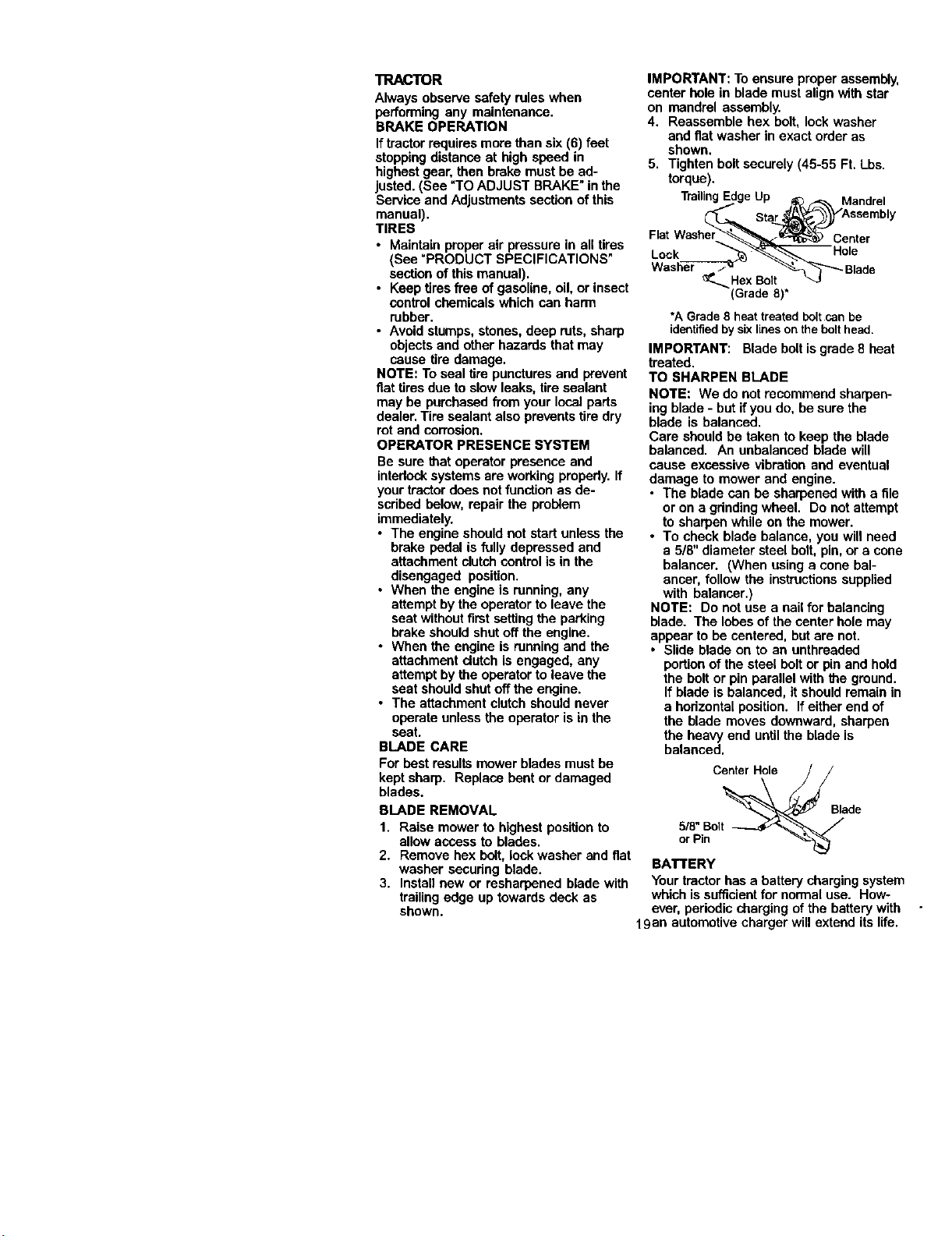
IMPORTANT: To ensure proper assembly,
center hole in blade must align with star
on mandrel assembly.
4. Reassemble hex bolt, lock washer
and fiat washer in exact order as
shown.
5. Tighten boltsecurely (45-55 Ft. Lbs.
torque),
TrailingEdgeUp j_ _, MandreI
_,_ Sta_Assembly
Flat Washer__Cente r
Lock ""_>_'__ Hole
Washer J_ _-_ _-T"_- Blade
_,, HexBolt _3
(Grade 8)*
*A Grade8heat treatedbolt can be
identifiedby sixlinesonthe bolt head.
IMPORTANT: Blade belt is grade 8 heat
treated.
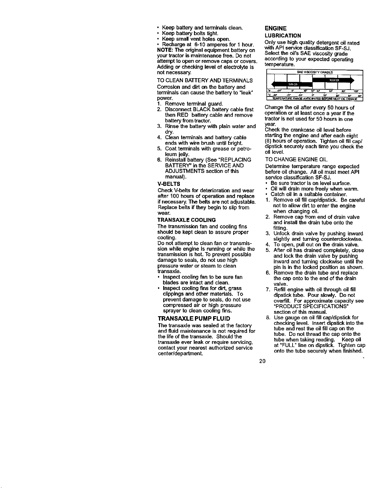
TO SHARPEN BLADE
NOTE: We do not recommend sharpen-
ing blade - but ifyou do, be sure the
blade is balanced.
Care should be taken to keep the blade
balanced. An unbalanced blade will
cause excessive vibration and eventual
damage to mower and engine.
• The blade can be sharpened with a file
or on a gdnding wheel. Do not attempt
to sharpen while on the mower.
• To check blade balance, you will need
a 5/8" diameter steel belt, pin, or a cone
balancer. (When using a cone bal-
ancer, follow the instructionssupplied
with balancer.)
NOTE: Do not use a nail for balancing
blade. The lobes of the center hole may
appear to be centered, but are not.
• Slide blade on to an unthreeded
portionof the steel boltor pin and hold
the belt or pin parallel with the ground.
If blade is balanced, it should remain in
a hedzontal position. If either end of
the blade moves downward, sharpen
the heavy end untilthe blade is
balanced.
Center Hole
" Blade
orPin -_
BATTERY
Your tractor has a battery charging system
which is sufficientfor normaluse. How-
ever, periodic charging of the batterywith
19an automotive charger will extend its life.
• Keep battery and terminals clean.
• Keep battery boltstight.
• Keep small vent holes open.
• Recharge at 6-10 amperes for 1 hour.
NOTE: The originalequipment battery on
your tractor ismaintenance free. Do not
attempt toopen or remove caps or covers.
Adding or checking level of electrolyte is
not necessary.
TO CLEAN BATTERY AND TERMINALS
Corrosion and dirt on the battery and
terminals can cause the battery to "leak"
power.
1. Remove terminal guard.
2. Disconnect BLACK battery cable first
then RED battery cable and remove
batteryfrom tractor.
3. Rinse the batterywith plain water and
dry.
4. Clean terminals and battery cable
ends with wire brush until bright.
5. Coat terminals with grease or petro-
leum jelly.
6. Reinstall battery (See =REPLACING
BATTERY" in the SERVICE AND
ADJUSTMENTS section of this
manual).
V-BELTS
Check V-belts for deterioration and wear
after 100 hours of operation and replace
ifnecessary. The belts are not adjustable.
Replace belts if they begin to slip from
wear.
TRANSAXLE COOLING
The transmissionfan and coolingfins
should be kept clean to assure proper
cooling,
Do not attempt to clean fan or transmis-
sion while engine is running or while the
transmission is hot.To prevent possible
damage to seals, do not use high
pressure water or steam to clean
transaxle.
• Inspect coolingfan to be sure fan
blades are intact and clean.
• Inspect coolingfins for dirt, grass
clippingsand other materials. To
prevent damage to seals, do not use
compressed air or high pressure
sprayer to clean cooling fins.
TRANSAXLE PUMP FLUID
The transaxle was sealed at the factory
and fluid maintenance is not required for
the life of the transaxle. Should the
transaxle ever leak or require servicing,
contact your nearest authorized service
center/department.
ENGINE
LUBRICATION
Only use high qualitydetergent oil rated
with API service classificationSF-SJ.
Select the oil'sSAE viscositygrade
according to your expected operating
temperature.
Change the oil after every 50 hours of
operation or at least once a year if the
tractor is not used for 50 hours in one
year.
Check the crankcase oil level before
starting the engine and after each eight
(8) hoursof operation. Tighten oilfillcap/
dipstick securely each time you check the
oil level.
TO CHANGE ENGINE OIL
Determine temperature range expected
before oilchange. All oil must meat API
service classification SF-SJ.
• Be sure tractor is on level surface.
• Oil will drain more freely when warm.
• Catch oil in a suitable container.
1. Remove oil fill cap/dipstick. Be careful
not to allow dirt to enter the engine
when changing oil.
2. Remove cap from end of drain valve
and install the drain tube onto the
fitting.
3. Unlock drain valve by pushing inward
slightly and turning counterclockwise.
4. To open, pull out on the drain valve.
5. After oil has drained completely, dose
and lock the drain valve by pushing
inward and turning clockwise until the
pin is in the locked position as shown.
6. Remove the drain tube and replace
the cap onto to the end of the drain
valve.
7. Refill engine with oilthrough oil fill
dipstick tube. Pour slowly. Do not
overfill. For approximate capacity see
"PRODUCT SPECIFICATIONS"
section of this manual.
8. Use gauge on oil fill cap/dipstick for
checking level. Insert dipstick into the
tube and rest the oil fill cap on the
tube. Do not thread the cap onto the
tube when taking reading. Keep oil
at "FULL" line on dipstick. Tighten cap
onto the tube securely when finished.
2O

Closed
and
Locked
Position
Cap
Oil DrainValve
Drain Tube
NOTE: Do not wash the paper cartridge
or use pressurized air, as this will
damage the cartddge.
6. Remove nut and cartridge plate.
7. Reinstall the pro-cleaner (cleaned
and oiled) over the paper cartridge.
8. Check rubber seal for damage and
proper positionaround stud. Replace
if necessary.
9. Reassemble air cleaner, cartridge
plate, and nut.
10. Reinstall air cleaner cover and secure
by tightening knob.
CLEAN AIR SCREEN
Air screen must be kept free of dirtand
chaff to prevent engine damage from
overheating. Clean with a wire brush or
compressed air toremove dirt and
stubbem dded gum fibers.
CLEAN AIR INTAKE/COOLING AREAS
To insure proper cooling, make sure the
grass screen, coolingfins, and other
external surfaces of the engine are kept
clean at all times.
Every 100 hours of operation (more often
under extremely dusty,dirtyconditions),
remove the blower housing and other
coolingshrouds. Clean the cooliog fins
and external surfaces as necessary. Make
sure the cooling shrouds are reinstalled.
NOTE: Operating the engine with a
blocked grass screen, dirty or plugged
coolingfins, and/or coolingshrouds
removed will cause engine damage due
to overheating.
AIR FILTER
Your engine will not run properly using a
dirty airfilter. Clean the foam we-cleaner
after every 25 hours of operation or every
season. Service paper cartridge every
100 hours of operation or every season,
whichever occurs first.
Service air cleaner more often under
dusty conditions.
1. Loosen knob and remove cover.
TO SERVICE PRE-CLEANER
2. Slide foam pre-cleaner off cartridge.
3. Wash it in liquid detergent and water.
4. Squeeze it dry in a clean cloth. Allow
it to dry.
5. Saturate it in engine oil. Wrap it in
clean, absorbent cloth and squeeze to
remove excess oil.
TO SERVICE CARTRIDGE
• Replace a dirty,bent, or damaged
cartridge.
ENGINE OIL FILTER
Replace the engine oil filter every season
or every other oilchange if the tractoris
used more than 100 hours in one year.
MUFFLER
Inspect and replace corroded muffler and
spark arrester (if equipped) as it could
create a fire hazard and/or damage.
SPARK PLUGS
Replace spark plugs at the beginning of
each mowing season or after every 100
hours of operation, whichever occurs first.
Spark plug type and gap setting are
shown in "PRODUCT SPECIFICATIONS"
section of this manual.
IN-LINE FUEL FILTER
The fuel filter should be replaced once
each season. Iffuel filter becomes
clogged, obstructingfuel flow to carbure-
tor, replacement is required.
1. With engine cool, remove filter and
plug fuel line sections.
2. Place new fuel filterin positionin fuel
line with arrow pointingtowards
carburetor.
3. Be sure there are no fuel line leaks
and damps are properly positioned.
4. Immediately wipe up any spilled
gasoline.
Clamp
Clamp
FuelFilt_
Cartridge
Foam
Pre-Cleaner
Rubber
Seal
21
CLEANING
• Clean engine, battery, seat, finish, etc.
of all foreign matter.
• Keep finished surfaces and wheels free
of all gasoline, oil,etc.
• Protect painted surfaces with automo-
tive typewax.
We do not recommend using a garden
hoseto clean your tractor unless the
electdcal system, muffler, airfilter and
carburetor are covered to keep water out.
Water in engine can result in a shortened
engine life.
,_CAUTION: BEFORE PERFORMING ANY SERVICE OR ADJUSTMENTS:
1. Depress brake pedal fully and set parking brake.
2. Place attachment clutch in "DISENGAGED" position•
3. Turn ignitionkey =OFF" and remove key.
4. Make sure the blades and all moving parts have completely stopped.
5. Disconnect spark plug wire from spark plug and place wire where itcannot
come in contact with plug.
TRACTOR
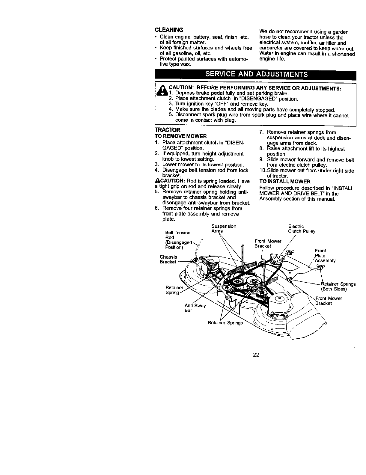
TO REMOVE MOWER
1. Place attachment clutch in "DISEN-
GAGED" position.
2. If equipped, tum height adjustment
knob to lowest setting.
3. Lower mower to its lowest position.
4. Disengage belt tension rod from lock
bracket.
_CAUTION: Rod is spdng loaded. Have
a tight gdp on rod and release slowly.
5. Remove retainer spdng holding anti-
swaybar to chassis bracket and
disengage anti-swaybar from bracket.
6. Remove four retainer springsfrom
front plate assembly and remove
plate•
Suspension
BeltTension Arms
Rod
(Disengaged_,;,
Position) _
Chassis
7. Remove retainer spdngsfrom
suspensionarms at deck and disen-
gage arms from deck.
8. Raise attachment liftto its highest
position.
9. Slide mower forward and remove belt
from electric clutchpulley.
10. Slide mower out from under rightside
oftractor.
TO INSTALL MOWER
Follow procedure described in "INSTALL
MOWER AND DRIVE BELT"in the
Assembly sectionof this manual.
Electric
Clutch Pulley
Front Mower
Bracket
Front
Plate
Bracket
Retainer
Anti-Sway
Bar
_r Springs
Springs
(Both Sides)
Mower
Bracket
22
TOLEVELMOWERHOUSING
Adjustthemowerwhiletractorisparked
onlevelgroundordriveway.Makesure
tiresareproperlyinflated(See=PROD-
UCT SPECIFICATIONS" section ofthis
manual). If tires are over or
under'inflated,you will not propedy adjust
your mower.
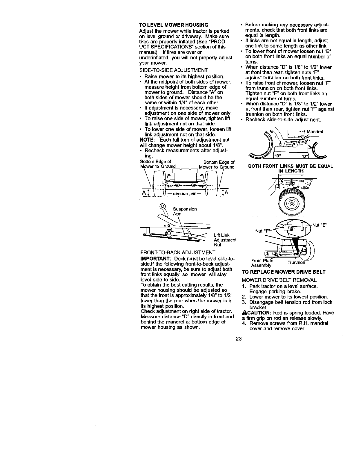
SIDE-TO-SIDE ADJUSTMENT
• Raise mower to its highest position.
• At the midpointof both sides of mower,
measure height from bottom edge of
mower to ground. Distance "A"on
both sides of mower should be the
same or within 1/4" of each other.
• If adjustment is necessary, make
adjustment on one side of mower only.
• To raise one side of mower, tighten lift
linkadjustment nut on that side.
• To lower one side of mower, loosen lift
link adjustment nut on that side.
NOTE: Each full turn ofadjustment nut
will change mower height about 1/8".
• Recheck measurements after adjust-
ing.
BottomEdgeof BottomEdgeof
Mowerto Ground Mowerto Ground
\ /
A_SUspensi°n
LiftLink
Adjustment
Nut
FRONT-TO-BACK ADJUSTMENT
IMPORTANT: Deck must be levelside-to-
side.If the following front-to-back adjust-
ment isnecessary, be sure to adjustboth
front linksequally so mower willstay
level side-to-side.
To obtain the best cutting results,the
mower housing should he adjusted so
that the front is approximately 1/8" to 1/2"
lower than the rear when the mower is in
its highest position.
Check adjustment on rightside of tractor.
Measure distance "D" directly in front and
behind the mandrel at bottom edge of
mower housing as shown.
• Before making any necessary adjust-
ments, check that both front links are
equal in length.
• If links are not equal in length, adjust
one linkto same length as other link.
• To lower front of mower loosen nut "E"
on both front links an equal number of
turns.
• When distance "D"is 1/8" to 1/2" lower
at front than rear, tighten nuts "F"
against trunnion on both front links.
• To raise front of mower, loosen nut =F"
from trunnionon both front links.
Tighten nut"E" on bothfront linksan
equal number of turns.
• When distance "D" is 1/8" to 1/2" lower
at front than rear, tighten nut "F" against
trunnionon both front links.
• Recheck side-to-side adjustment.
== oo Mandrel
BOTH FRONT LINKS MUST BE EQUAL
IN LENGTH
Nut "E"
Nut
Front Plate Trunnion
Assembly
TO REPLACE MOWER DRIVE BELT
MOWER DRIVE BELT REMOVAL
1. Park tractor on a level surface.
Engage parking brake.
2. Lower mower to its lowest position.
3. Disengage belt tension rod from lock
bracket.
• LCAUTION: Rod is spring loaded. Have
a firm grip on rod an release slowly.
4. Remove screws from R.H. mandrel
cover and remove cover.
23
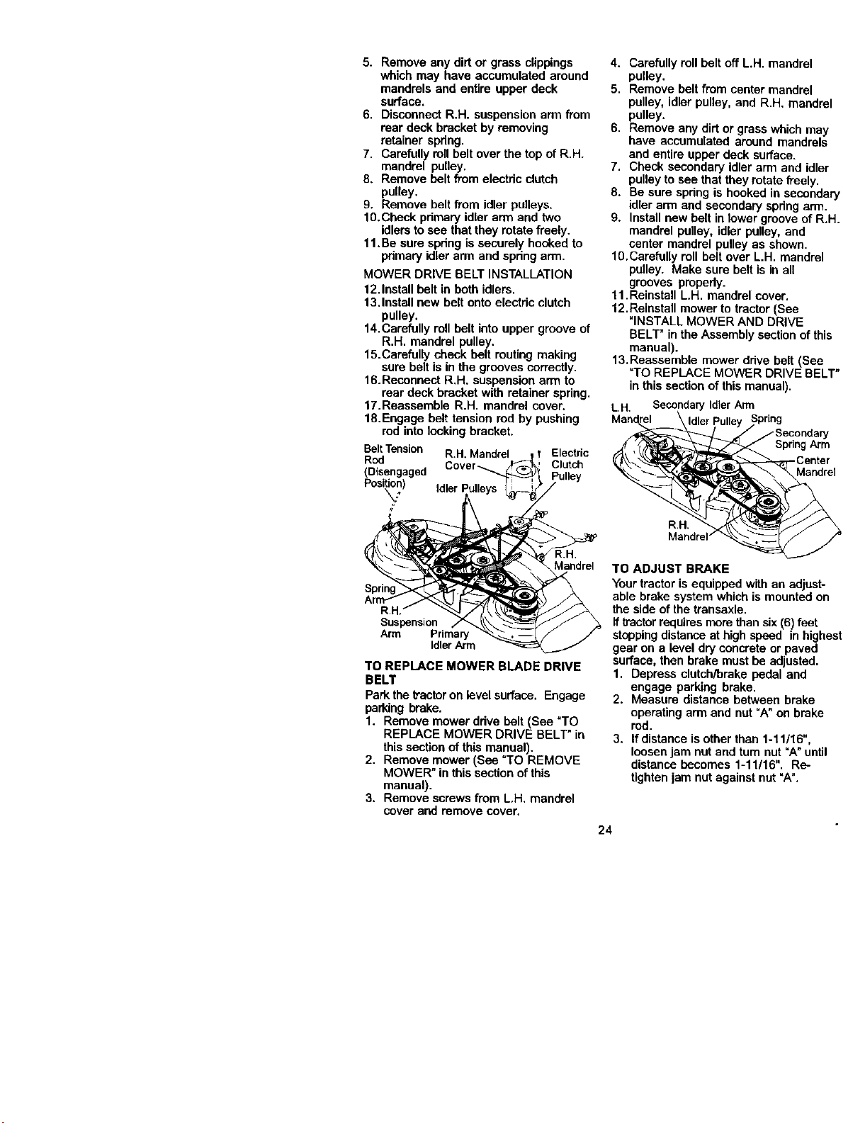
5. Removeanydirtorgrassclippings
whichmayhaveaccumulatedaround
mandrelsandentireupperdeck
surface.
6. DisconnectR.H.suspensionarmfi'om
reardeckbracketbyremoving
retainerspdng.
7. CarefullyrollbeltoverthetopofR.H.
mandrel pulley.
8. Remove belt from electdc clutch
pulley.
9. Remove belt from idler pulleys.
10.Cbeck pdmary idler arm and two
idlersto see that they rotate freely.
11.Be sure spdng is securely hooked to
pdmary idler arm and spdng arm.
MOWER DRIVE BELT INSTALLATION
12.Install belt in both idlers.
13.Install new belt onto electric clutch
pulley.
14.Carefully roll belt into upper groove of
R.H. mandrel pulley.
15.Carefully check belt routing making
sure belt is in the grooves correctly.
16.Reconnect R.H. suspension arm to
rear deck bracket with retainer spring.
17.Reassemble R.H. mandrel cover.
18.Engage belt tension red by pushing
rod into locking bracket.
BeltTension R.H,Mandrel Electric
Rod
(Disengaged Cover_ Clutch
Posi_n) Idler
R.H.
Mandrel
Suspension
Arm Primary
Idler Arm
TO REPLACE MOWER BLADE DRIVE
BELT
Park the tractoron levelsurface. Engage
parking brake.
1. Remove mower ddve belt (See "TO
REPLACE MOWER DRIVE BELT* in
this section of this manual).
2. Remove mower (See "TO REMOVE
MOWER" in this section ofthis
manual).
3. Remove screws from L.H. mandrel
cover and remove cover.
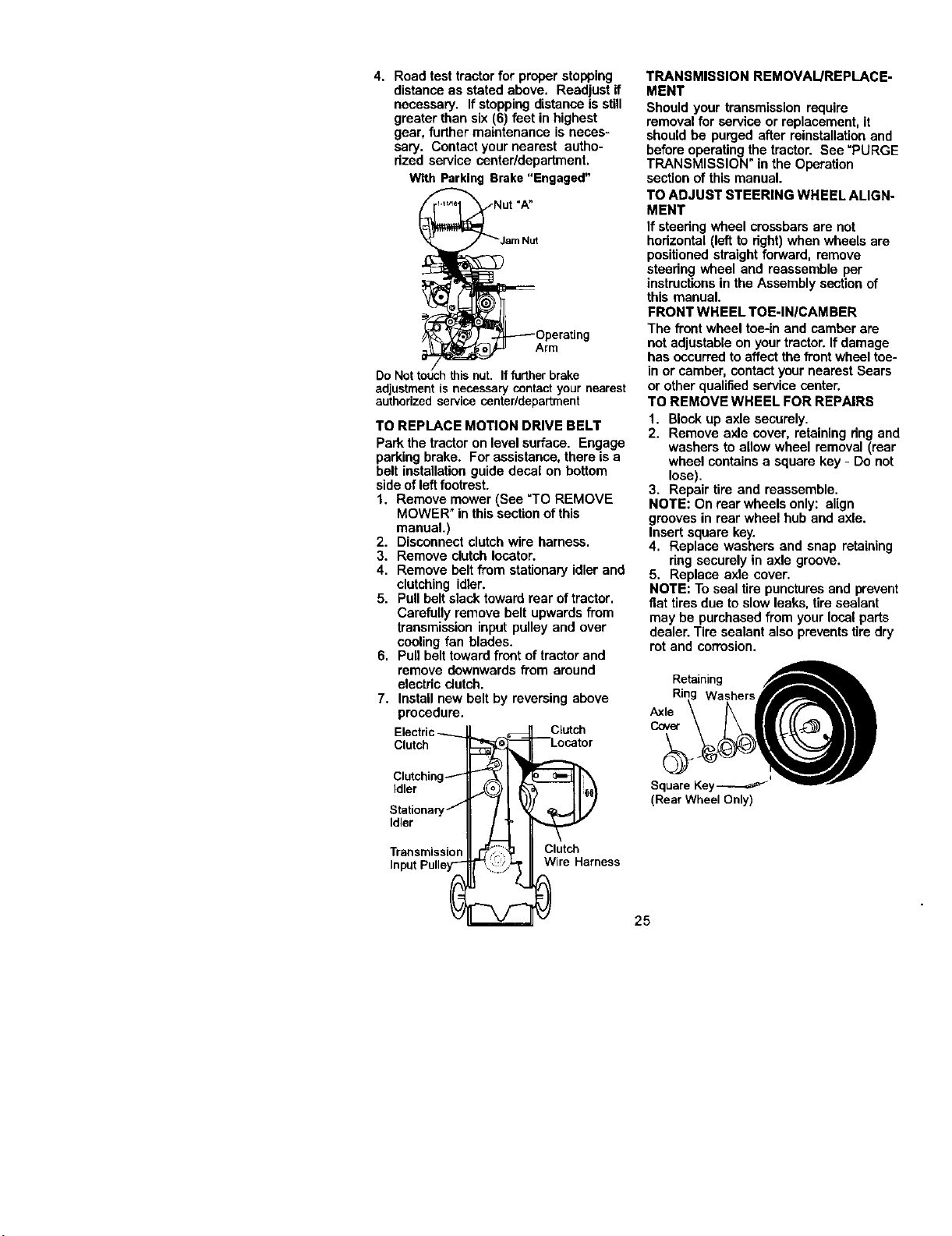
4. Carefully roll belt off L.H. mandrel
pulley.
5. Remove belt from center mandrel
pulley, idler pulley, and R.H. mandrel
pulley.
6. Remove any dirt or grass which may
have accumulated around mandrels
and entire upper deck surface.
7. Check secondary idler arm and idler
pulley to see thatthey rotate freely.
8. Be sure spring is hookedin secondary
idler arm and secondary spring arm.
9. Install new belt in lower groove of R.H.
mandrel pulley, idler pulley, and
center mandrel pulley as shown.
10.Carefully roll belt over L.H. mandrel
pulley. Make sure belt is in all
grooves pmpedy.
11.Reinstall L.H. mandrel cover.
12.Reinstall mower to tractor (See
"INSTALL MOWER AND DRIVE
BELT" in the Assembly section of this
manual).
13.Reassemble mower drive belt (See
"TO REPLACE MOWER DRIVE BELT"
in this section of this manual).
L.H. SecondaryIdlerArm
Mandrel
SpdngArm
Mandrel
R.H.
Mandrel/
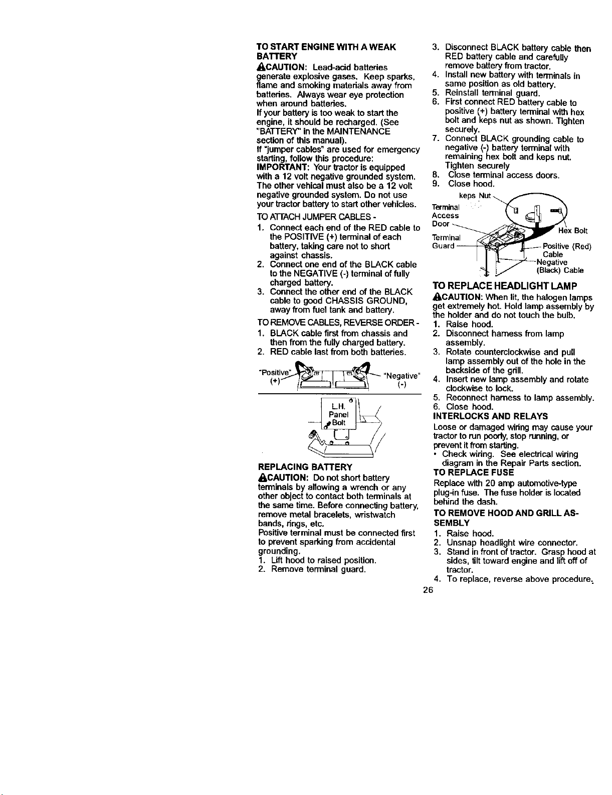
TO ADJUST BRAKE
Yourtractor is equipped with an adjust-
able brake system which is mounted on
the side of the transaxle.
ff tractor requiresmorethan six(6) feet
stoppingdistance at high speed in highest
gear on a level dry concrete or paved
surface, then brake must be adjusted.
1. Depress clutch/brake pedal and
engage parking brake.
2. Measure distance between brake
operating arm and nut "A" on brake
rod.
3. Ifdistance is other than 1-11/16",
loosen jam nut and tam nut "A" until
distance becomes 1-11/16". Re-
tightenjam nut against nut "A".
24
4. Roadtesttractorforproperstopping
distanceasstatedabove.Readjustif
necessary.Ifstoppingdistanceisstill
greaterthansix(6)feetinhighest
gear,furthermaintenanceisneces-
sary.Contactyournearestautho-
rized service center/department.
With Parking Brake "Engaged"
Arm
Do Not b h this nut. If further brake
adjustment is necessary contact your nearest
authorized service center/department
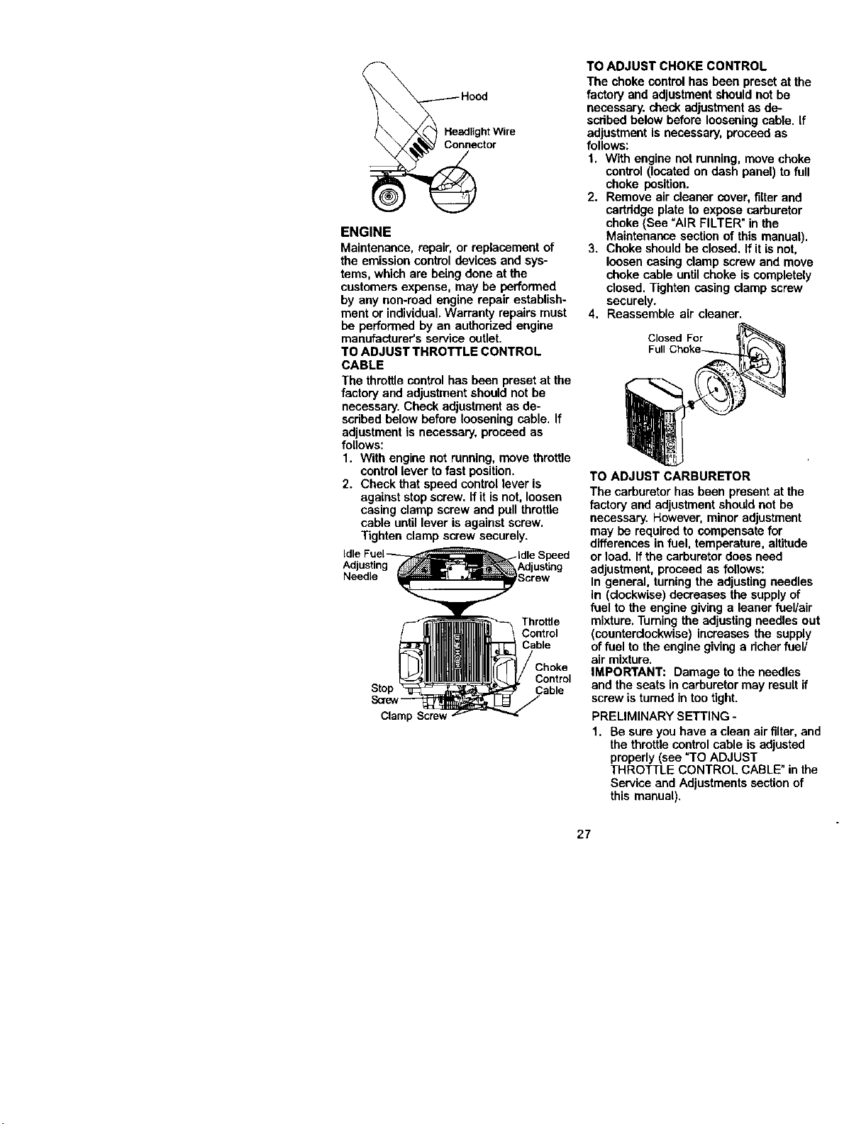
TO REPLACE MOTION DRIVE BELT
Park the tractoron level surface. Engage
parking brake. For assistance, there is a
belt installation guide decal on bottom
side ofleft footrest.
1, Remove mower (See "TO REMOVE
MOWER" in this section of this
manual.)
2. Disconnect clutch wire harness.
3. Remove clutch Iocetor.
4. Remove belt from stationary idler and
clutching idler.
5. Pullbelt slack toward rear of tractor.
Carefully remove belt upwards from
transmission input pulley and over
cooling fan blades.
6. Pull belt toward front of tractor and
TRANSMISSION REMOVAL/REPLACE-
MENT
Should your transmission require
removal for service or replacement, it
should be purged after reinstallation and
before operatingthe tractor. See =PURGE
TRANSMISSION" in the Operation
section of this manual.
TO ADJUST STEERING WHEEL ALIGN-
MENT
If steering wheel crossbars are not
hodzontal (left to dght) when wheels are
positionedstraight forward, remove
steedng wheel and reassemble per
instructionsin the Assembly section of
this manual.
FRONT WHEEL TOE-IN/CAMBER
The front wheel toe-in and camber are
not adjustableon yourtractor. If damage
has occurred toaffect the front wheel tee-
in or camber, contact your nearest Sears
or other qualifiedservice canter.
TO REMOVE WHEEL FOR REPAIRS
1. Blockup axle securely.
2. Remove axle cover, retaining dng and
washers to allow wheel removal (rear
wheel containsa square key - Do not
lose).
3. Repair tire and reassemble.
NOTE: On rear wheels only: align
grooves in rear wheel hub and axle.
Insert square key.
4. Replace washers and snap retaining
dng securely in axle groove.
5. Replace axle cover.
NOTE: To seal tire punctures and prevent
fiat tires due to slow leaks, tire sealant
may be purchased from your local parts
dealer. Tire sealant also prevents tire dry
rot and corrosion.
remove downwards from around ZZ_g_g _
electric dutch.
7. Install new belt by reversing above
procedure.
Electric Clutch
Clutch Locator
Clutchin_
Idler (Rear Wheel Only)
TransrniStati°naldlerssion I _ _ 25Square Key_
Input Pulle_ Wire Harness
TO START ENGINE WITH A WEAK
BATTERY
_CAUTION: Lead-acid batteries
generate explosive gases. Keep sparks,
flame and smoking matedals away from
batteries. Always wear eye protection
when around battedes.
If yourbattery istooweak to start the
engine, it should be recharged. (See
"BATTERY" in the MAINTENANCE
section of this manual).
If "jumper cables" are used for emergency
starting,follow this procedure:
IMPORTANT: Yourtractor is equipped
with a 12 volt negative grounded system.
The other vehical must also be a 12 volt
negative grounded system. Do not use
your tractor batteryto start other vehicles.
TO ATTACHJUMPER CABLES-
1. Connect each end of the RED cable to
the POSITIVE (+) terminal of each
battery, takingcare not toshort
against chassis.
2. Connect one end of the BLACK cable
tothe NEGATIVE (-) terminal offully
charged battery.
3. Connect the other end of the BLACK
cable to good CHASSIS GROUND,
away from fuel tank and battery.
TO REMOVECABLES, REVERSE ORDER -
1. BLACK cable first from chassis and
then from the fully charged battery.
2. RED cable last from both batteries.
"Positive" . • .
Negative
(*) (.)
REPLACING BATTERY
_-CAUTION: Do notshort battery
terminals by allowing a wrench or any
other objectto contact both temlinals at
the same time. Before connecting battery,
remove metal bracelets, wristwatch
bands, degs, etc.
Positiveterminal must be connected first
to prevent sparking from accidental
grounding.
1. Lift hood to raised position.
2. Remove terminal guard.
3. Disconnect BLACK battery cab|e then
RED battery cable and carefully
remove battery from tractor.
4. Install new battery with terminals in
same position as old battery.
5. Reinstall terminal guard.
6. First connect RED battery cable to
positive (+) battery terminal with hex
bolt and keps nut as shown. "[]ghten
securely.
7. Connect BLACK grounding cable to
negative (-) battery terminal with
remaining box bolt and keps nut.
Tighten securely
8. Close terminal access doors.
9. Close hood.
keps Nut
Terminal
Acces_
Door x Bolt
Terminal
Guarc__Positive (Red)
Cable
I
_; I/ (Black)Cable
TO REPLACE HEADLIGHT LAMP
ACAUTION: When lit, the halogen lamps
get extremely hot. Hold lamp assembly by
the holder and do not touch the bulb.
1. Raise hood.
2. Disconnect harness from lamp
assembly.
3. Rotate counterclockwise and pull
lamp assembly out of the hole in the
backside of the gdll.
4. Insert new lamp assembly and rotate
clockwise to lock.
5. Reconnect harness to lamp assembly.
6. Close hood.
INTERLOCKS AND RELAYS
Looseor damaged widng may cause your
tractortorun poorly,stoprunning, or
preventitfrom starting.
• Check wiring. See electrical wiring
diagram in the Repair Parts section.
TO REPLACE FUSE
Replace with 20 amp automotive-typo
plng4n fuse. The fuse holderislocated
behind the dash.
TO REMOVE HOOD AND GRILL AS-
SEMBLY
1. Raise hood.
2. Unsnap headlight wire connector.
3. Stand in front of tractor. Grasp hood at
sides, tilt toward engine and liftoff of
tractor.
4. To replace, reverse above procedure:
26
_e_g H°°d
'oWl'e
ENGINE
Maintenance, repair, or replacement of
the emissioncontrol devices and sys-
tems, which are being done at the
customersexpense, may be performed
by any non-road engine repair establish-
ment or individual.Warranty repairs must
be performed by an authorized engine
manufacturer's service outlet.
TO ADJUST THROTTLE CONTROL
CABLE
The throttlecontrol has been preset at the
factory and adjustment should not be
necessary. Check adjustment as de-
scdbed below before looseningcable. If
adjustment is necessary, proceed as
follows:
1. With engine not running, move throttle
controllever to fast position.
2. Check that speed controllever is
against stop screw. If it isnot, loosen
casing clamp screw and pull throttle
cable until lever is against screw.
Tighten clamp screw securely.
Adjusting
Needle
Throttle
Control
Control
Stop Cable
Clamp Screw
TO ADJUST CHOKE CONTROL
The choke control has been preset at the
factory and adjustment should not be
necessary, check adjustment as de-
scdbed below before loosening cable. If
adjustment is necessary, proceed as
follows:
1. With engine not running, move choke
control (located on dash panel) to full
choke position.
2. Remove air cleaner cover, filter and
cartridge plate to expose carburetor
choke (See "AIR FILTER" in the
Maintenance section of this manual).
3. Choke shouldbe closed. If it isnot,
loosen casing clamp screw and move
choke cable untilchoke is completely
closed. Tighten casing clamp screw
securely.
4, Reassemble air cleaner.
Closed For
F_
TO ADJUST CARBURETOR
The carburetor has been present at the
factory and adjustment should not be
necessary. However, minor adjustment
may be required to compensate for
differences in fuel, temperature, altitude
or load. If the carburetor does need
adjustment, proceed as follows:
In general, turningthe adjusting needles
In (clockwise)decreases the supplyof
fuel to the engine givinga leaner fuel/air
mixture. Turningthe adjusting needles out
(counterclockwise) increases the supply
of fuel to the engine giving a dcherfuel/
air mixture.
IMPORTANT: Damage tothe needles
and the seats in carburetor may result if
screw isturned in tootight.
PRELIMINARY SETTING -
1. Be sure you have a clean air filter,and
the throttle controlcable is adjusted
properly (see "TO ADJUST
THROTTLE CONTROL CABLE" in the
Service and Adjustments section of
this manual).
27
2. With engine off turn idle fuel adjusting
needle in (clockwise) closing it finger
tight and then turn out (counterclock-
wise) 1tum.
FINAL SETTING -
1. Start engine and allow to warm for five
minutes. Make final adjustments with
engine running and shift/motion
control lever in neutral (N) position.
NOTE: The high idle is set at the factory
and cannot be adjusted.
2. Idle soeed settina - With throttle
control lever in slow position, engine
should idle at 1200 RPM. If engine
idles too slow or fast, turn idle speed
adjustingscrew in or out until correct
idle is attained.
3. Idle fuel needle settin9 - With throttle
control lever in slow position, turn idle
fuel adjusting needle in (clockwise)
until engine speed decreases and
then turn out (counterclockwise)
approximately 3/4 turnto obtain the
beat low speed performance.
4. Recheck idle speed. Readjust if
necessary,
ACCELERATION TEST -
5. Move throttle control leverfrom slow to
fast position. If engine hesitates or
dies, turn idle fuel adjusting needle
out (counterclockwise) 1/8 turn.
Repeat test and continue toadjust, if
necessary, until engine accelerates
smoothly.
High speed stop isfactory adjusted. Do
notadjust-damage may result.
IMPORTANT: Never tamper with the
engine governor,which is factory setfor
proper engine speed. Overspeeding the
engine above the factory high speed
settingcan be dangerous. If you think the
engine-governed high speed needs
adjusting, contact your nearest Sears or
other qualified service center, which has
proper equipment and expedence to
make any necessary adjustments.
28
Immediatelyprepareyourtractorfor
storage at the end of the season or if the
tractor willnot be used for 30 days or
more.
• I,CAUTION: Never storethe trectorwith
gasoline in the tank inside a building
where fumes may reach an open flame or
spark. Allow the engine to cool before
storing in any enclosure.
TRACTOR
Remove mower from tractor for winter
storage. When mower is to be storedfor
a period of time, clean it thoroughly,
remove all dirt, grease, leaves, etc. Store
in a clean, dry area.
1. Clean entire tractor (See "CLEANING"
in the Maintenance section of this
manual).
2. Inspect and replace belts, if necessary
(See belt replacement instructionsin
the Service and Adjustments section
of this manual).
3. Lubricate as shown in the Mainte-
nance section of this manual.
4. Be sure that all nuts, bolts and screws
are securelyfastened. Inspect moving
partsfor damage, breakage and wear.
Replace if necessary.
5. Touch up all rusted or chipped paint
surfaces; sand lightly before painting.
BA'n'ERY
• Fullycharge the batteryfor storage.
• After a periodof time in storage, battery
may require recharging.
• To help prevent corrosionand power
leakage during long periods of storage,
battery cables should be disconnected
and battery cleaned thoroughly (see
"TO CLEAN BATTERY AND TERMI-
NALS" in the Maintenance section of
this manual).
• After cleaning, leave cables discon-
nected and place cables where they
cannot come in contact with battery
terminals.
• If battery isremoved from tractorfor
storage, do not store battery directlyon
concrete or damp surfaces.
ENGINE
FUEL SYSTEM
IMPORTANT: It isimportantto prevent
gum deposites from forming in essential
fuel system parts such as carburetor, fuel
hose, or tank during storage. Also,
expedance indicates that alcohol
blended fuels (called gasohol or using
ethanol or methanol) can attract moisture
which leads to separation and formation
of acids dudng storage. Acidic gas can
damage the fuel system of and engine
while in storage.
1. Drainthe fuel tank.
2. Start the engine and let it run untilthe
fuel lines and carburetor are empty.
• Never use engine or carburetor cleaner
products in the fuel tank or permanent
damage may occur.
• Use fresh fuel next season.
NOTE: Fuel stabilizer is an acceptable
alternative in minimizingthe formation of
fuel gum deposits during storage. Add
stabilizer to gasoline in fuel tank or
storage container. Alwaysfollowthe mix
ratio found on stabilizer container. Run
engine at least 10 minutes after adding
stabilizerto allow the stabilizer to reach
the carburetor. Do not drain the gas tank
and carburetor if using fuel stabilizer.
ENGINE OIL
Drain oil (with engine warm) and replace
with clean engine oil. (See =ENGINE" in
the Maintenance section of this manual).
CYLINDER(S)
1. Remove spark plug(s).
2. Pour one ounce of oil through spark
plug hole(s) into cylinder(s).
3. Turn ignitionkey to =START" position
for a few seconds to distributeoil.
4. Replace with new spark plug(s).
OTHER
• Do not store gasoline from one season
to another.
• Replace your gasoline can if your can
startsto rust. Rust aed/or dirtin your
gasoline will cause problems.
• If possible, store your tractorindoors
and cover it to give protectionfromdust
and dirt.
• Cover your tractorwith a suitable
protective cover that does not retain
moisture. Do not use plastic. Plastic
cannot breathe which allows conden-
sation to form and will cause your
tractorto rust.
IMPORTANT: Never cover tractorwhile
engine and exhaust areas are stillwarm.
29

TROUBLESHOO_NGCHART
PROBLEM
Will notstart
Plardto start
Enginewill not
turn over
Engine clicks but
will not start
Loseofpower
CAUSE
1. Out offuel.
2. Engine not "CHOKED"
properly.
3. Engine flooded.
4. Bad spark plug.
5. Dirty air filter.
6. Dirty fuel filter.
7. Water in fuel.
8. Loose or damaged wiring.
9. Carburetorout ofadjustment.
10.Engine valves out of
adjustment.
1. Dirty air filter.
i2. Bad spark plug.
3. Weak or dead battery.
4. Dirty fuel filter.
5. Stale or dirty fuel.
6. Loose or damaged widng.
7. Carburetoroutof adjustment.
8. Engine valves out of
adjustment.
1. Brake pedal not depressed.
2. Attachment clutchis
engaged.
3. Weak or dead battery.
4. Blown fuse.
5. Corroded battery terminals.
6. Loose or damaged widng.
7. Faulty ignition switch.
8. Faulty solenoid or starter.
9. Faulty operator presence
switch(es).
1. Weak or dead battery.
2. Corroded battery terminals.
3. Loose or damaged widng.
4. Faultysolenoid or starter.
1. Cutting too much grass/too
fast.
2. Throttle in "CHOKE"
position.
CORRECTION
1. Fillfuel tank.
2. See "TO START ENGINE"
in Operation section.
3. Wait several minutes before
attempting tostart.
4. Replace spark plug.
5. Clean/replace air filter.
6. Replace fuel filter.
7. Drain fuel tank and carbure-
tor,refilltankwith fresh
gasoline and replace fuel
filter.
8. Check all widng.
9. See "To Adjust Carburetor"
in Service Adjustments
section.
10.Contact a Sears or other
qualified service center.
1. Clean/replace air filter.
2. Replace spark plug.
3. Recharge or replace battery.
4. Replace fuel filter.
5. Drainfuel tank and reflUwith
fresh gasoline.
6. Check all wiring.
7. See =ToAdjust Carburetor"in
Service Adjustments
section.
8. Contact a Sears or other
qualified service center.
1. Depress brake pedal.
2. Disengage attachment
clutch.
3. Recharge or replace battery.
4. Replace fuse.
5. Clean battery terminals.
6. Check all wiring.
7. Check/replace ignition
switch.
8. Check/replace solenoid or
starter.
9. Contact a Sears or other
qualified service center.
1. Recharge or replace battery.
2. Clean battery terminals.
3. Check all widng.
4. Check/replace solenoid o_
starter.
1. Set in =Higher Cut" position/
reduce speed.
2. Adjust throttlecontrol.
3O
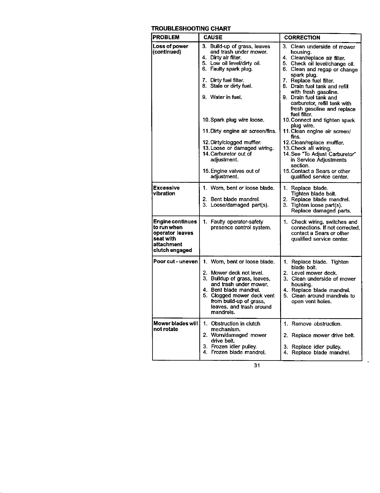
TROUBLESHOOTING CHART
CAUSE CORRECTIONPROBLEM
Loss of power
continued)
Excessive
vibration
Engine continues
to run when
operator leaves
seat with
attachment
;lutch engaged
Poorcut-uneven
Mower blades will
not rotate
3. Build-upof grass, leaves
and trash under mower.
4. Dirty airfilter,
5. Low oil level/dirty oil.
6. Faultyspark plug.
7. Dirtyfuel filter.
8. Stale or dirtyfuel.
9. Water in fuel,
10.Spark plug wire loose.
11. Dirty engine air screen/fins.
12. Dirty/clogged mufflen
13,Loose or damaged widng.
14,Carburetor out of
adjustment.
15.Engine valves out of
adjustment.
1. Worn, bent or loose blade.
2. Bent blade mandrel.
3. Loose/damaged part(s).
1. Faulty operator-safety
presence control system.
1. Worn, bent or loose blade.
2. Mower deck not level.
3. Buildupof grass, leaves,
and trash under mower,
4. Bent blade mandrel.
5. Clogged mower deck vent
from build-upof grass,
leaves, and trash around
mandrels.
1. Obstruction in clutch
mechanism.
2. Worn/damaged mower
drive belt.
3. Frozen idler pulley.
4. Frozen blade mandrel.
3. Clean underside of mower
housing.
4. Clean/replace air filter.
5. Check oil level/change oil.
6. Clean and regap or change
spark plug.
7. Replace fuel filter.
8. Drain fuel tank and refill
with fresh gasoline.
9. Drain fuel tank and
carburetor, refilltank with
fresh gasoline and replace
fuel filter.
10.Connect and tighten spark
plug wire.
11.Clean engine air screen/
fins.
12.Clean/raplace muffler.
13.Check all widng.
14.See "ToAdjust Carburetor"
in Service Adjustments
section.
15. Contact a Sears or other
qualified service center.
1. Replace blade.
Tighten blade bolt.
2. Replace blade mandrel.
3. Tighten loose part(s).
Replace damaged parts.
1. Check wiring, switches and
connections. If notcorrected
contacta Sears or other
qualified service center.
1. Replace blade. Tighten
blade bolt.
2. Level mower deck.
3. Clean underside of mower
housing.
4. Replace blade mandrel.
5. Clean around mandrels to
open vent holes.
1. Remove obstruction.
2. Replace mower drive belt.
3. Replace idler pulley.
4. Replace blade mandrel.
31
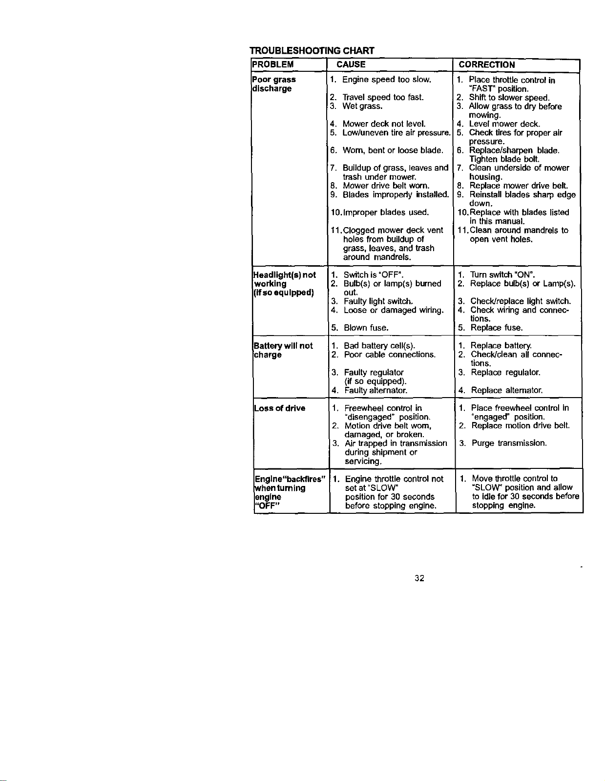
TROUBLESHOOTING
PROBLEM
Poorg_ss
discha_e
Headlight(s)not
working
ifso equipped)
3attery will not
:harge
_OSSof drive
CHART
CAUSE
1. Engine speed too slow,
2. Travelspeed too fast.
3, Wet grass,
4. Mower deck not level.
5. Low/uneven tire air pressure,
6. Worn, bent or loose blade,
7, Buildupof grass, leavesand
trash under mower,
8, Mower drive belt worn.
9. Blades impropody installed.
10.Improper blades used.
11,Clogged mower deck vent
holes from buildup of
grass, leaves, and trash
around mandrels,
1. Switch is "OFF".
2. Bulb(s) or lamp(s) burned
out.
3. Faulty light switch,
4. Loose or damaged wiring.
5. Blown fuse.
1. Bad battery cell(s).
2. Poor cable connections,
13. Faulty regulator
(if so equipped).
4. Faulty alternator.
1. Freewheel control in
"disengaged" position.
2, Motion drive belt worn,
damaged, or broken.
3. Air trapped in transmission
during shipment or
servicing.
CORRECTION
1. Place throttlecontrol in
"FAST" position.
2. Shift to slower speed.
3. Allow grass to dry before
mowing.
4. Level mower deck.
5. Check tires for proper air
pressure.
6. Replace/sharpen blade.
Tighten blade bolt.
7. Clean underside of mower
housing.
8. Replace mower drive belt.
9, Reinstall blades sharp edge
down.
10,Replace with blades listed
in this manual.
11.Clean around mandrels to
open vent holes,
1. Turn switch"ON".
2. Replace bulb(s) or Lamp(s).
3. Checldreplace light switch.
4. Check wiring and connec-
tions.
5. Replace fuse,
1. Replace battery.
2. Check/clean all connec-
tions.
3. Replace regulator.
4. Replace alternator.
1. Place freewheel control in
"engaged" position.
2. Replace motiondrive belt.
3. Purge transmission.
Engine"backfires" 1. Engine throttle control not 1. Move throttlecontrolto
_henturning set at "SLOW" "SLOVV_ position and allow
engine position for 30 seconds to idlefor 30 seconds before
"OFF" before stopping engine, stopping engine.
32
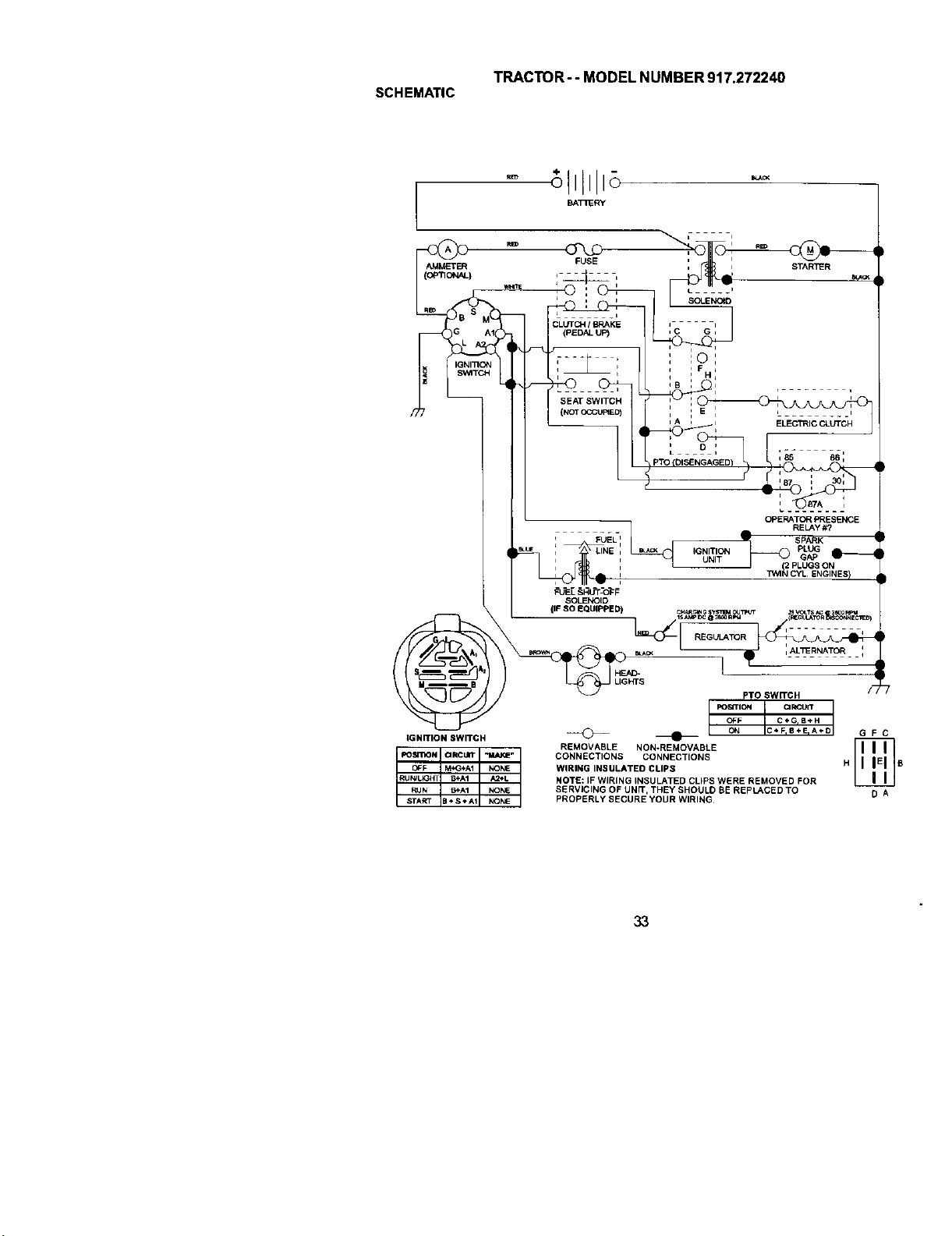
TRACTOR-- MODEL NUMBER 917.272240
SCHEMATIC
AMMETER
(OP_ON_L)
O_3
FUSE
CLUTO-I I BRAKE J .... i
(PEDAL UP) , C G ,
I i(_ I
STARTER
SEATSWITCH
(i_T OCCUP=EO)
IGNITION SWITCH
OPERATOR PRESENCE
_ _ RELAy#?
SPARK ;
IGNITION _ PLUG
i UNIT GAP _
i _1_ PLUGS ON
CYL ENGINES !
FUEL SHUT-OFF
SOLENOID
(IF SO EQUIPPED)
• ,_._ ;_%,%_ _o ,%_o)
UGHTS
F
PTO SWffCH
FOE4TIQN ClRCUR
OFF C÷GrB+H
REMOVABLE NON-REMOVABLE
CONNECTIONS CONNECTIONS
WIRING INSULATED CLIPS H
NOTE: IF WIRING INSULATED CLIPS WERE REMOVED FOR
SERVICING OF UNIT, THEY SHOULD BE REPLACED TO
PROPERLY SECURE YOUR WIRING
GFC
BA
:3,3
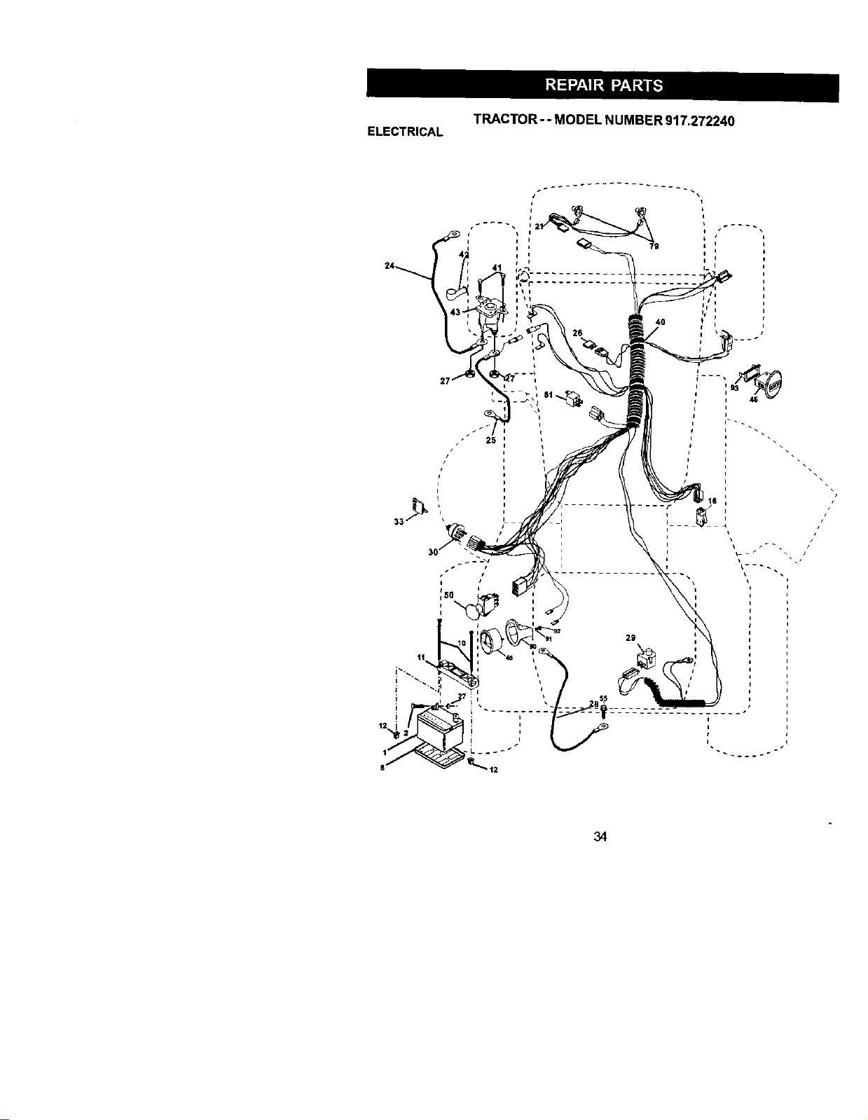
TRACTOR - - MODEL NUMBER 917.272240
ELECTRICAL
jl
12
8-
11
i
34
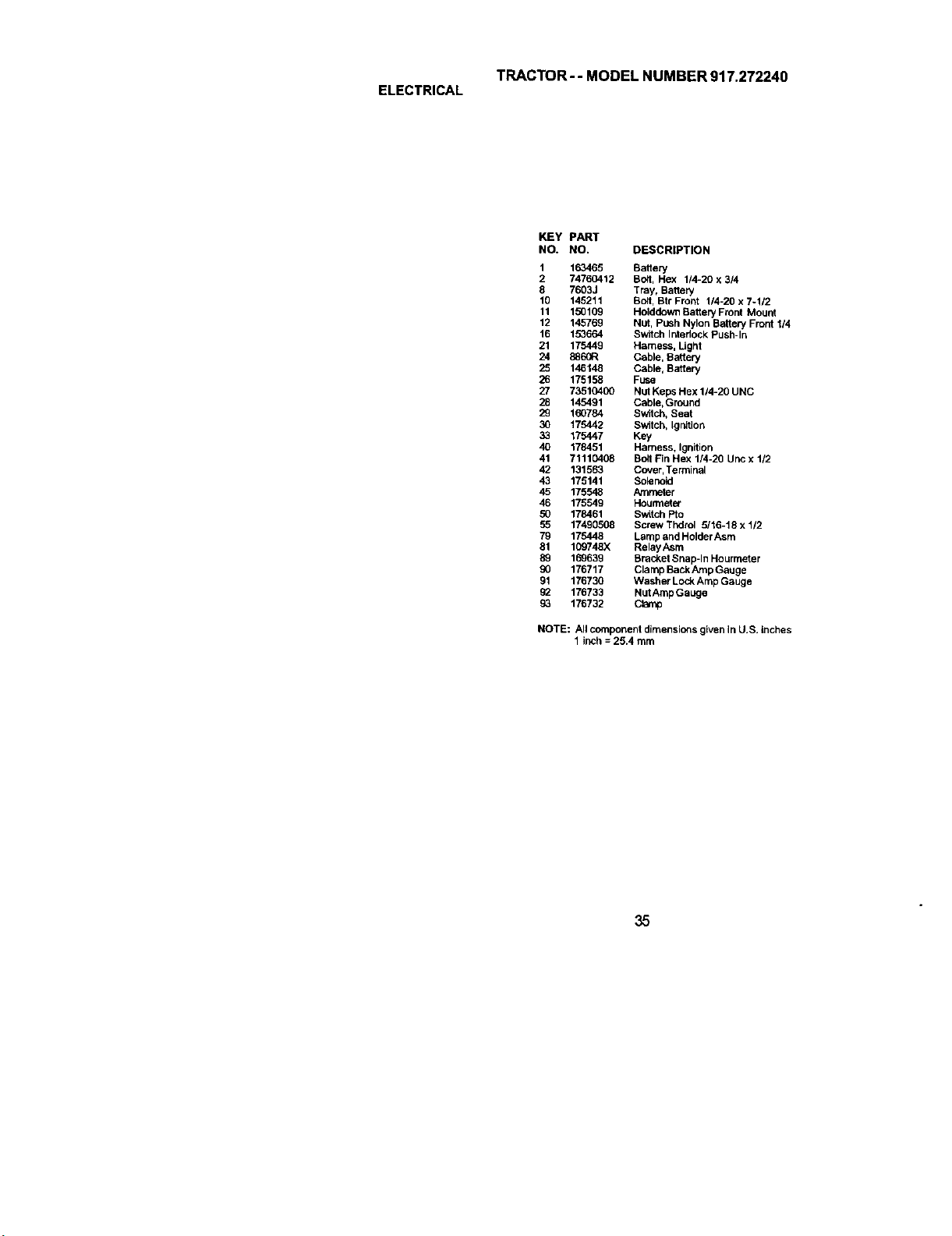
TRACTOR-- MODEL NUMBER 917.272240
ELECTRICAL
KEY PART
NO. NO. DESCRIPTION
1 163465 Battery
2 74760412 Bott, Hex 1/4-20 x 3/4
8 7603J Tray, Battery
10 145211 Bolt, Btr Front 1/4-20 x 7_1/2
11 150109 Holddown Battery Front Mount
12 145769 Nut, Push Nylon Bakery Front 1/4
16 153664 Switch Interlock Push-In
21 175449 Harness, Light
24 886GR Cable, Battery
25 146148 Cable, Battery
26 175158 Fuse
27 73510400 NUt Keps Hex 1/4-20 UNC
28 145491 Cable,Ground
29 160784 Switch, Seat
30 175442 Switch, Ignition
33 175447 Key
40 178451 Harness, Ignition
41 71110408 Bcll Fin Hex 1/4-20 Unc x 1/2
42 131563 Cover,Terminal
43 175141 Solenoid
45 175548 Arnrnnter
46 175549 Hourmeter
50 178461 Switch Pto
55 17490568 Screw Thdrol 5/16-18 x 1/2
79 175448 Lamp and Holder Asm
81 109748X RelayAsrn
89 169639 Bracket Snap-In Hourmeter
176717 Clamp BackAmp Gauge
91 176730 Washer LockAmp Gauge
93 176733 NutAmp Gauge
93 176732 Clamp
NOTE: Allcomponent dimensions given in U.S. inches
1 inch = 25.4 mm
35
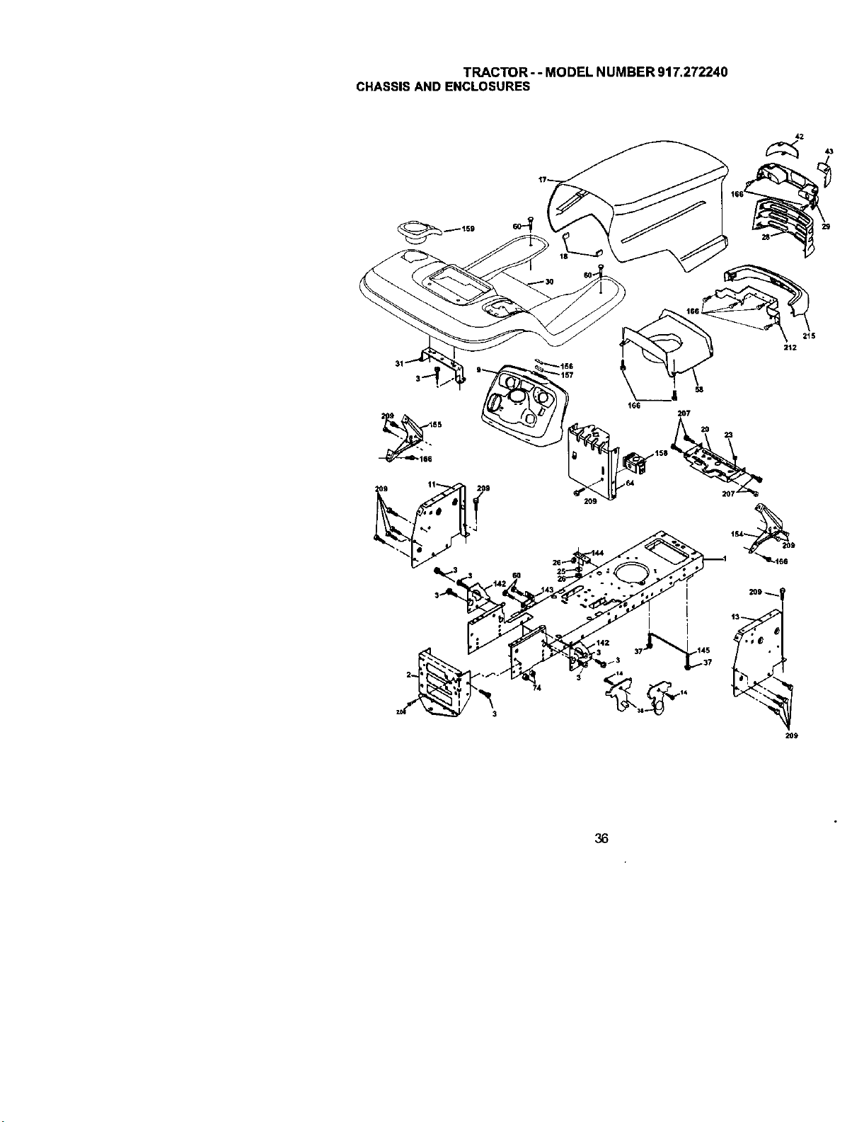
TRACTOR--MODELNUMBER917.272240
CHASSISANDENCLOSURES
36

TRACTOR - - MODEL NUMBER 9t7.272240
CHASSISAND ENCLOSURES
KEY PART
NO. NO. DESCRIPTION
1 174619 Chassis
2 176554
3 17060612 Screw, 3/8-16 x 314
9 172542)(418 Dash
10 STD533710 Bolt, Carriage 3/8-16 x 1
11 174996 Panel, Dash, LH
13 175256)(010 Panel, Dash, RH
14 17490608 Screw Thdrol 3/8-16 x 1/2
17 172540)(615 Hood Assembly
18 126938X BumperHood
20 156437 Plate Batter,/
23 124028X BushingSnap
29 19131312 Washer 13138x 13116 x 12 Gauge
26 STD541437 Locknut, Hex, with Insert 3/8-16 UNC
28 174948)(418 Grille
29 t74944X4t8 Lightbox Dust
30 175692X615 Fender/Footrest
31 139976 Bracket, Fender/Support
37 1749(}508 Screw, Thdrol. 5116-18 x 1/2 TYT
38 175710 Bracket Asrn Pivot Mower Rear
42 172549X999 Lens Lh
43 172544X999 Lens Rh
58 174993 Duct Hood
59 110436X Bushing, Snap, Split
60 STD533707 Bolt Rdhd Sqnk 318-16 UNC x 3/4
64 174997 Dash Lower
74 ST0541437 NutCmwnlock 3/_-16 UNC
142 175702 Plate Reinforcement
143 154966 Bracket Swaybar Chassis
144 176582 Bracket Footrest
145 156524 Rod Pivot Chassis/Hood
154 174679 Bracket Dash Rh
155 174680 Bracket Dash Lh
156 163806 Striker Plate
157 163806 MagnetYTGT
198 162037 parking Brake Bkrt
159 199123)(418 Cupholder Sit BIk
166 164863 HWHDH:-Lo.#13-16 x 3/4
206 170169 Bolt Shoulder 6/16-19
207 17670508 Screw Thdrol 5/16-18 x 1/2
209 17000612 Scraw Hexwsh Thdr 3/8o16 x 3/4
212 174988 Bracket Pivot Hood
215 172543X616 Bumper
NOTE: All component dimensions given in U.S. inches
1 inch = 26.4 rnm
37
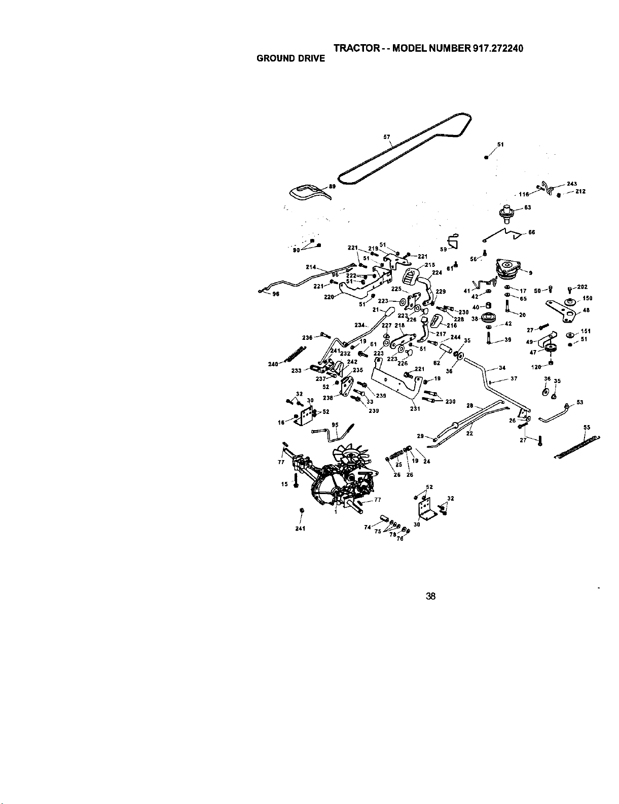
TRACTOR-- MODEL NUMBER 917.272240
GROUNDDRIVE
51
./
38
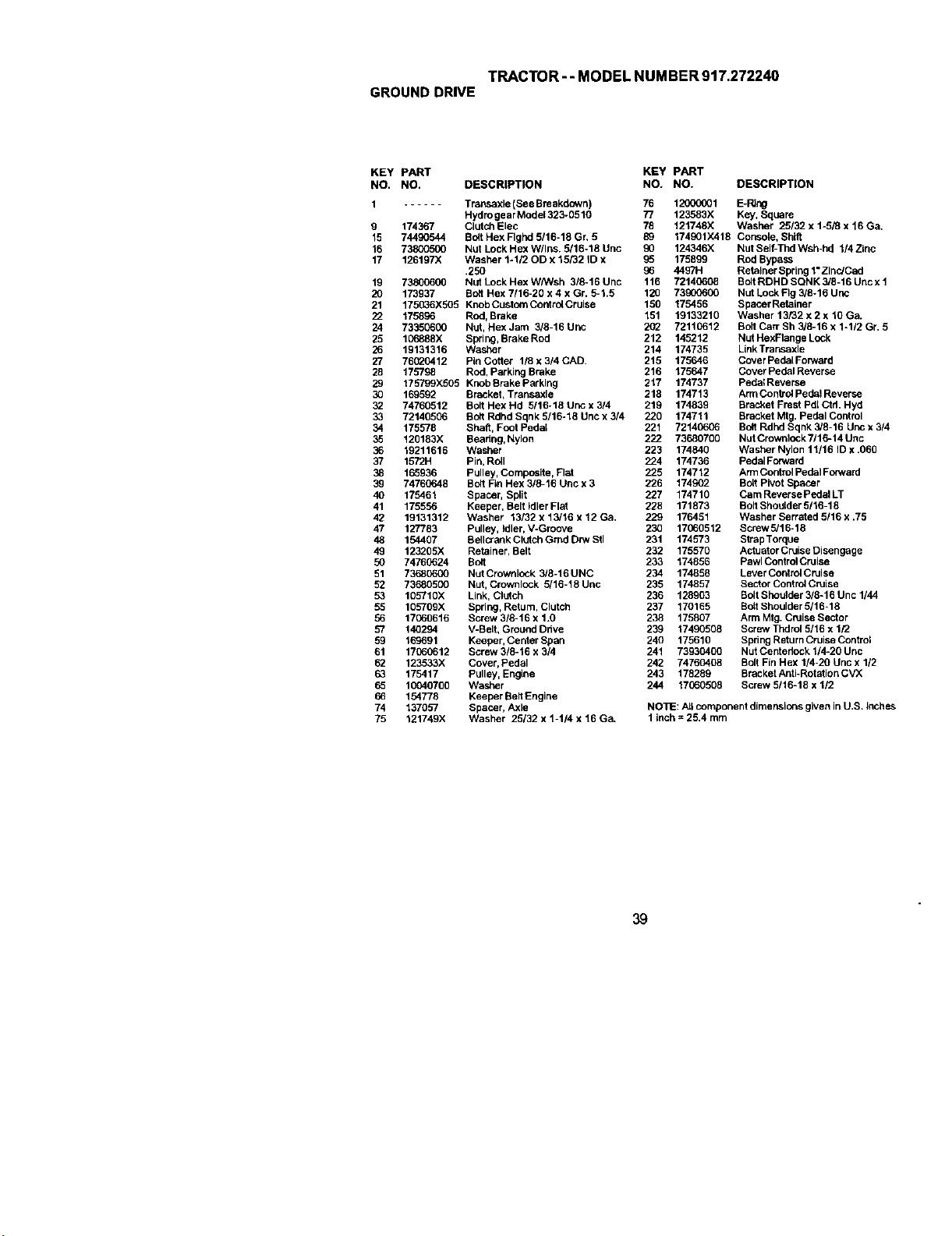
TRACTOR- - MODEL NUMBER 917.272240
GROUNDDRIVE
KEY PART KEY PART
NO. NO. DESCRIPTION NO. NO. DESCRIPTION
1 ...... Transaxle (See Breakdown) 76 120(_001 B-PJng
Hydro gear Model 323-0510 77 123583X Key, Square
9 174367 Clutch Elec 76 121748X Washer 25/32 x 1-5/3 x 16 Ga,
15 74490544 BoltHexFIghd5116-18Gr, 5 89 174901X416 Console, Shtlt
16 73800500 Nut LockHex W/Ins. 5/16-18 Unc 90 124346X NutSelf-Thd Wsh-hd 1/4 Zinc
17 126197X Washer 1-1/20D x 15/32 ID x 95 175899 Rod Bypass
.250 90 4497H Retather Spring 1"ZincJCad
19 73800690 NutLockHexWhNsh 318-16Unc 116 72149008 BoltRDHDSQNK3/8-16Uncx1
90 173937 Batt Hex 7/16-20 x 4 x Gr, 5-1.5 120 73900600 Nut Lock Fig 3/8-16 Unc
21 175036X505 KnobCutaomCorrirolCruise 150 175456 SpacerRatatner
22 175896 Rod, Brake 151 19133210 Washer 13/32 x 2 x 10 Ga.
24 73350600 Nut, HexJam 3/8-16Unc 202 72110612 BoltCmrSh3/8-16x1*l12Gr, 5
25 106888X Spring, Brake ROd 212 145212 Nut HexFtange Lock
26 19131316 Washer 214 174735 LinkTrar'_axle
27 76(_0412 PLnCotter I/8x3/4CAD. 215 175646 CoverPedalForward
28 175798 Rod, Parking Brake 216 175647 Cover Pedat Reverse
29 175799X505 Knob Brake Parking 217 174737 Pedol Reverse
30 169592 BrackeL Transaxle 218 174713 Arm Control Pedat Reverse
32 74760512 Bolt Hex Hd 5/16-18 uric x 3/4 219 174839 Bracket Frest Pdl Ctd. Hyd
33 72140506 Bolt Rdhd Sqnk 5/16-18 Uric x 3/4 220 174711 Bracket Mtg. Pedal Control
34 175578 Shaft, Foot Pedal 221 72140606 Bolt Rdhd Sqnk 3/8-16 Unc x 3/4
35 120183X Bearing, Nylon 222 73680790 NutCrownlock 7/16-14 Unc
36 19211616 Washer 223 174840 Washer Nylon 11/16 ID x .060
37 1572H Pin, Roll 224 174736 PedalForward
38 165936 Pulley, Composite, Flat 225 174712 ArmControl PedalForward
39 74760648 Bolt Fin Hex 3/8-16 Uric x 3 226 174902 Bolt Pivot Spacer
40 175461 Spacer, Split 227 174710 CarnReversePedalLT
41 175556 Keeper, Belt idler Flat 228 171873 Bolt Shoolder 5/16-18
42 19131312 Washer 13/32 x 13/16 x 12 Ga. 229 176451 Washer Serrated 5116 x .75
47 127783 Pulley, Idler, V-Groove 230 17060512 ScrewS/16-18
48 154467 Bellcrank Clutch Grad Dtw Stl 231 174573 Strap Torque
49 123205X Retainer, Belt 232 175570 Actuator Cruise Disengage
50 74760624 Bo4t 233 174856 Pawl ControlCruise
51 73680600 NutCrownlock 3/8-16 UNC 234 174858 Lever Control Cruise
52 73680500 Nut, Crowolock 5/16-18Unc 235 174857 SectorControlCruise
53 105710X Link, Clutch 236 128903 Bolt Sheolder 3/8-16 Unc 1/44
55 105709X Spring, Return, Clutch 237 170165 BattShoulder 5/16-18
56 17060616 Screw 3/8-16 x 1.0 238 175807 Arm Mtg. Cruise Sector
57 140294 V-Belt, Ground Drive 239 17490508 Screw Thdrol 5/16 x 1/2
59 169691 Keeper, Center Span 240 175610 Spring RaturnCruise Contrat
61 17900612 Screw 3/8-16 x 314 241 73930400 Nut Centedock 1/4-20 Unc
62 123533X Cover, Pedal 242 74760408 Bolt Fin Hex 1/4-20 Uric x 1/2
63 175417 Pulley, Engine 243 178289 BracketAn6-RotationCVX
65 10040700 Washer 244 17900508 Screw 5/16-18 x 112
66 154778 Keeper BeltEngine
74 137057 Spacer, Axle NOTE: Atl component dimensions given in U.S. lnche_
75 121749X Washer 25/32 x 1-1/4 x 16 Ga. 1 Lnch= 25.4 mm
39
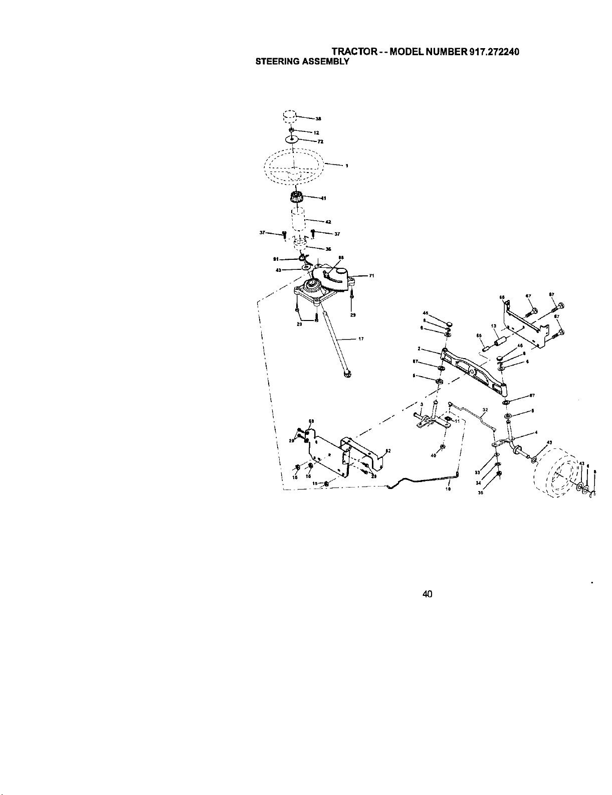
TRACTOR-- MODEL NUMBER 917.272240
STEERINGASSEMBLY
43_
29
Zg
4O
6T ST
/S
j$
40
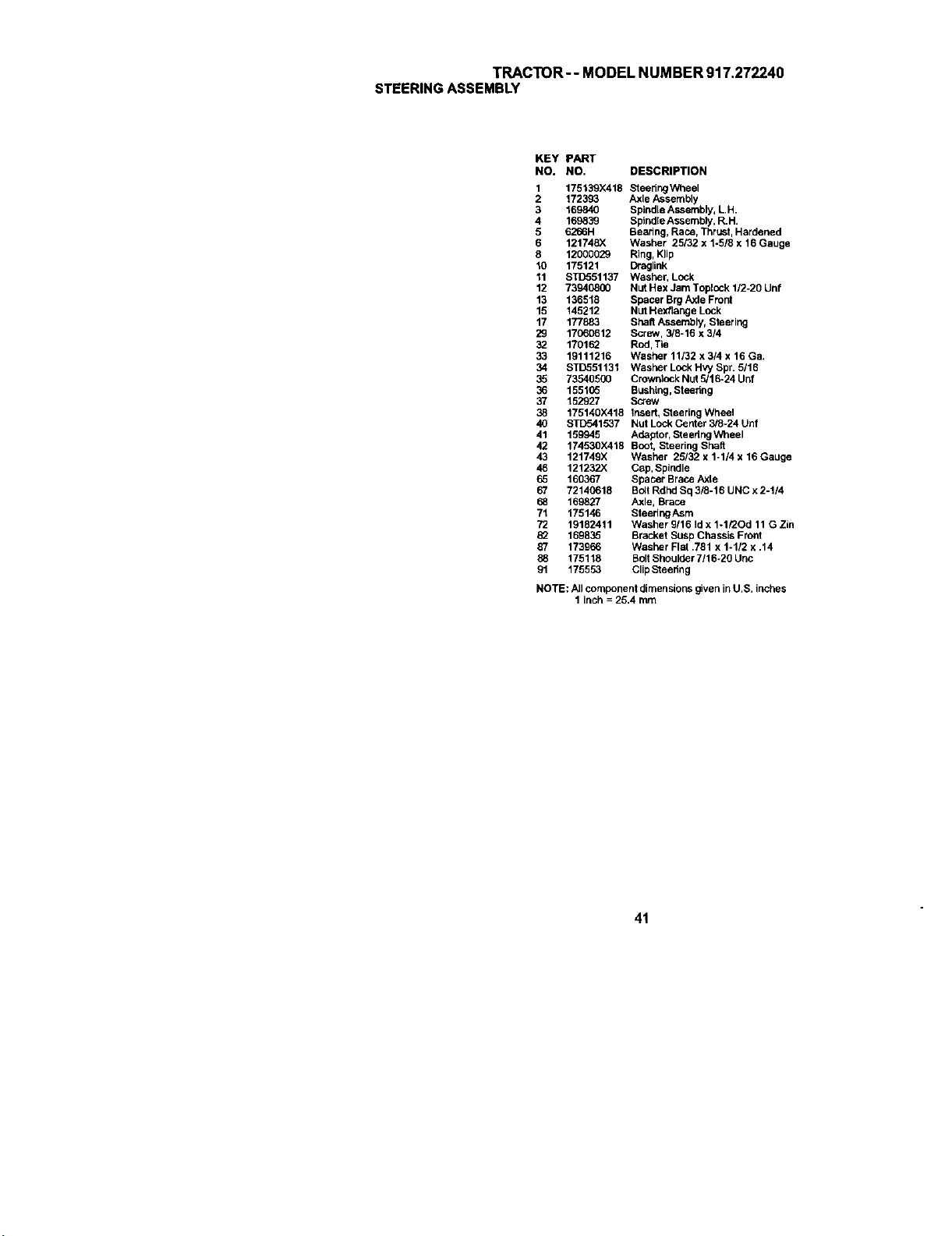
TRACTOR-- MODEL NUMBER 917.272240
STEERINGASSEMBLY
KEY PART
NO. NO. DESCRIPTION
1
2
3
4
5
6
8
10
11
12
13
15
17
29
32
33
34
35
36
37
38
4O
41
42
43
46
65
67
68
71
72
87
88
91
175139X418 Steering Wheel
172393 Axle Assembly
169840 Spindle Assembly, L.H.
169839 Sptnd[eAssembly, R.H.
6266H Bearing, Race, Thrust, Hardened
121748X Washer 25132 x 1-5/6 x 16 Gauge
12000029 Ring, Klip
175121 Draglink
STD551137 Washer, Lock
73940800 Nut Hex Jam Toplock 1/2-20 Unf
136518 Spacer Brg Axle Frout
145212 Nut Hexflange Lock
177883 Shaft Assembly, Steering
17060612 Screw, 3/8-16 X 3/4
1701_ Rod, Tie
19111216 Washer 11/32 x 314 x 16 Ga.
STD551131 Washer Lock Hvy Spr. 5/16
73540500 Crownlock Nut 5/16-24 Unf
155105 Bushing, Steedng
152927 Screw
175140X418 Insed, Steerlng Wheel
STD541537 Nut Lock Center 3/8/24 Unf
159945 Adaptor, Steedng Wheel
174530X41B Boot, Steering shaft
121749X Washer 25/32 x 1-1/4 x 16 Gauge
121232)( Cap, Spindle
160367 Spacer Brace AxLe
72140618 Bo4tRdhd Sq 3/8-16 UNC x 2-1/4
169827 Axle, Brace
175146 SteeringAsm
19182411 Washer 9/16 Jdx 1-1/30d 11 G Zin
169835 Bracket Susp Chassis Front
173966 Washer Flat ,781 x 1-1/2 x ,14
175118 Bolt Shoulpor 7116-20 Unc
175553 ClipSteering
NOTE: AJIcomponent dimensions given in U.S. inches
1 inch = 25.4 mm
41
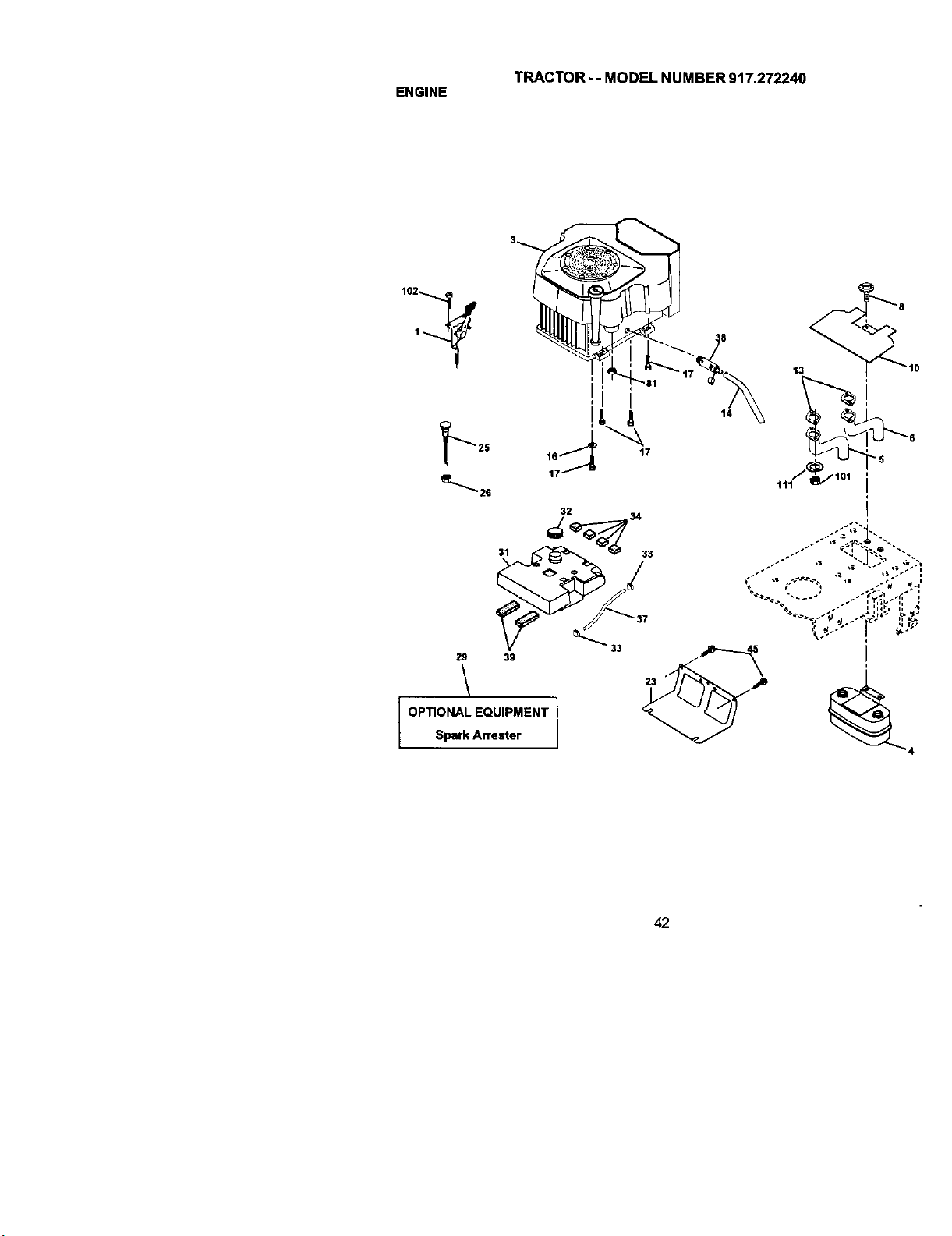
TRACTOR- - MODEL NUMBER 917.272240
ENGINE
14
32
29/ 39 _._
OPTIONAL EQUIPMENT
Spark Arrester
42
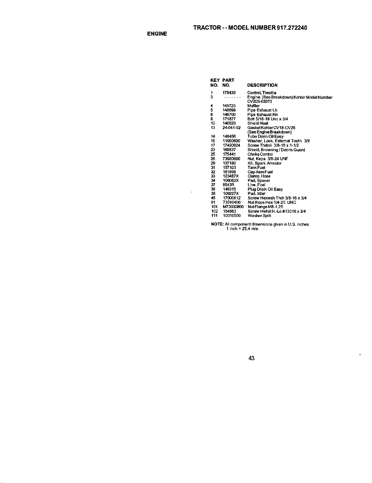
TRACTOR - - MODEL NUMBER 917.272240
ENGINE
KEY PART
NO. NO, DESCRIPTION
1 175439 Control,Throttle
3 Engine, (See Breakdown) KohlerModel Number
CV20S-65570
4 149723 Muffler
5 146699 Pipe Exhaust Lh
6 146700 Pipe Exhaust Rh
8 171877 Bolt 5116-18 Unc x 3/4
10 146629 ShieldHeat
13 24-041-02 Gasket KohlerCV18-CV26
(See Engine Breakdown)
14 148456 Tube Drain Oil Easy
16 11050600 Washer, Lock, External TOOth 3/8
17 17490624 Scow Thdrol 3/8-16 x 1-1/2
23 169837 Shield, Browning / Debris Guard
25 175441 CbekeControl
26 73920600 NUt, Keps 3/8-24 UNF
29 137180 Kff, Spark Arrestor
31 157103 Tank Fuel
32 161696 CapAsm Fuel
33 123487X Clamp,Hose
34 106082X Pad, Spacer
37 8543R Line, Fuel
38 148315 Plug Drain Oil Easy
39 109227X Pad, Idler
45 17(X)0612 Screw Hexwsh Thdr 3/8-16 x 3/4
81 73510400 Nut Keps Hex 114-20 UNC
101 M73030800 Nut Flange M8-1,25
102 164863 Screw Hwhd H.-Lo #13016 x 3/4
111 10010500 Wasber Split
NOTE: Allcomponent dimensions given in U.S. inches
1 inch = 25.4 mm
43
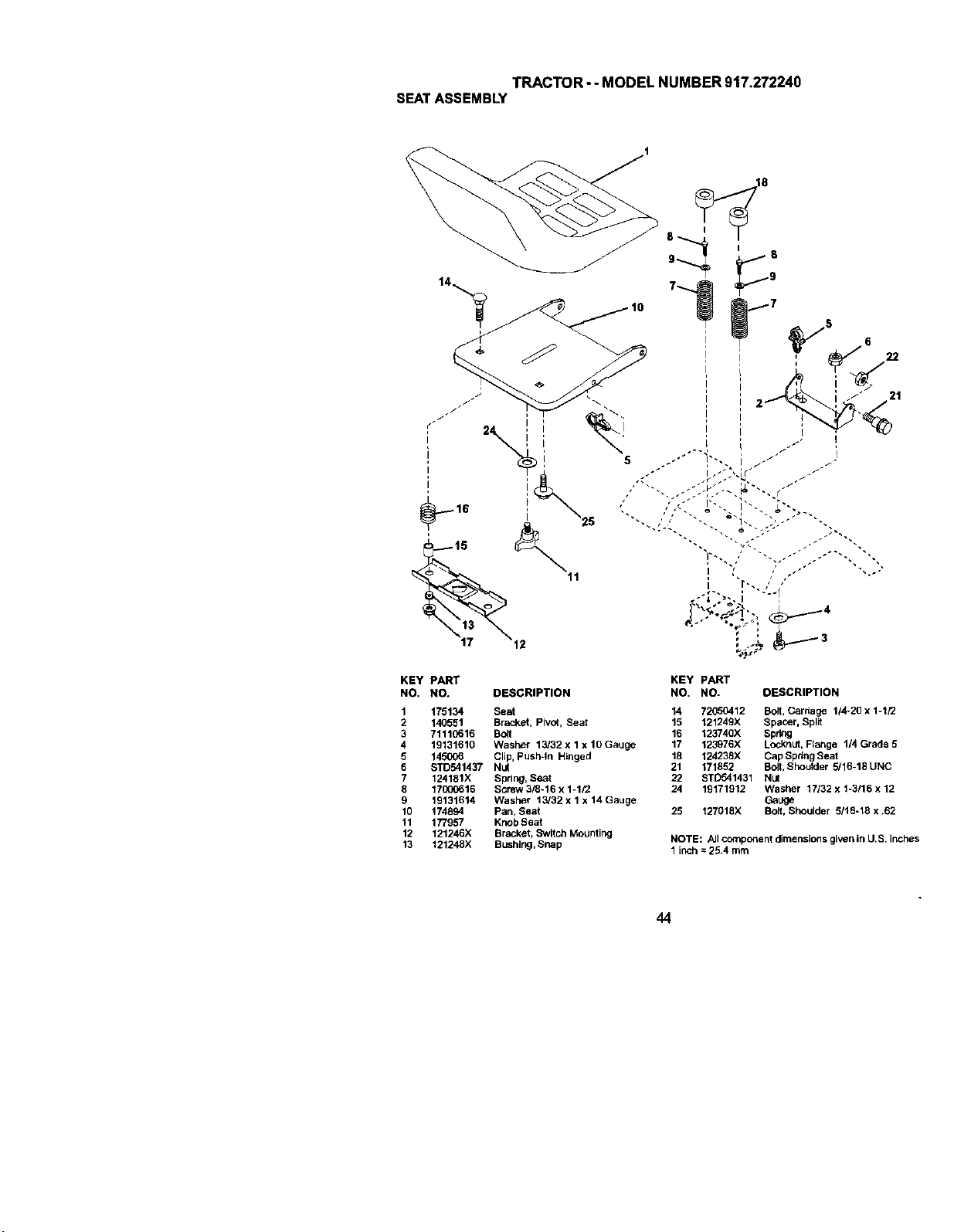
TRACTOR- - MODEL NUMBER 917.272240
SEATASSEMBLY
KEY PART
NO. NO. DESCRIPTION
1 175134 Seat
2 140551 Bracket, Pivot, Seat
3 71110616 Bolt
4 19131610 Washer 13/32 x lx 10 Gauge
5 145006 Clip, Push-in Hinged
6 STD541437 Nut
7 124181X Spring, Seat
8 17000616 Screw 318-16 x 1-1/2
9 19131614 Washer 13/32 x 1 x 14 Gauge
10 174894 Pan, Seat
11 177957 KnobSeat
12 121246X Bracket, Switch Mounting
13 121248X Bushing,Snap
KEY PART
NO. NO. DESCRIPTION
14 72050412 Bolt, Cardage 1/4-20 x 1-1/2
15 121249X Spacer, Split
16 123740X Spltt_g
17 123976X Locknut, Ftange 1/4 Grade 5
18 124238X Cap Spdng Seat
21 171852 Bolt, Sheulder 5J16-18 UNC
22 STD541431 Nut
24 19171912 Washer 17132 x t-3116 x 12
Gauge
25 127018X Bolt, Shoulder 5/16-18 x .62
NOTE: All component dimensions given in U.S. inches
1 inch = 25.4 mrn
44
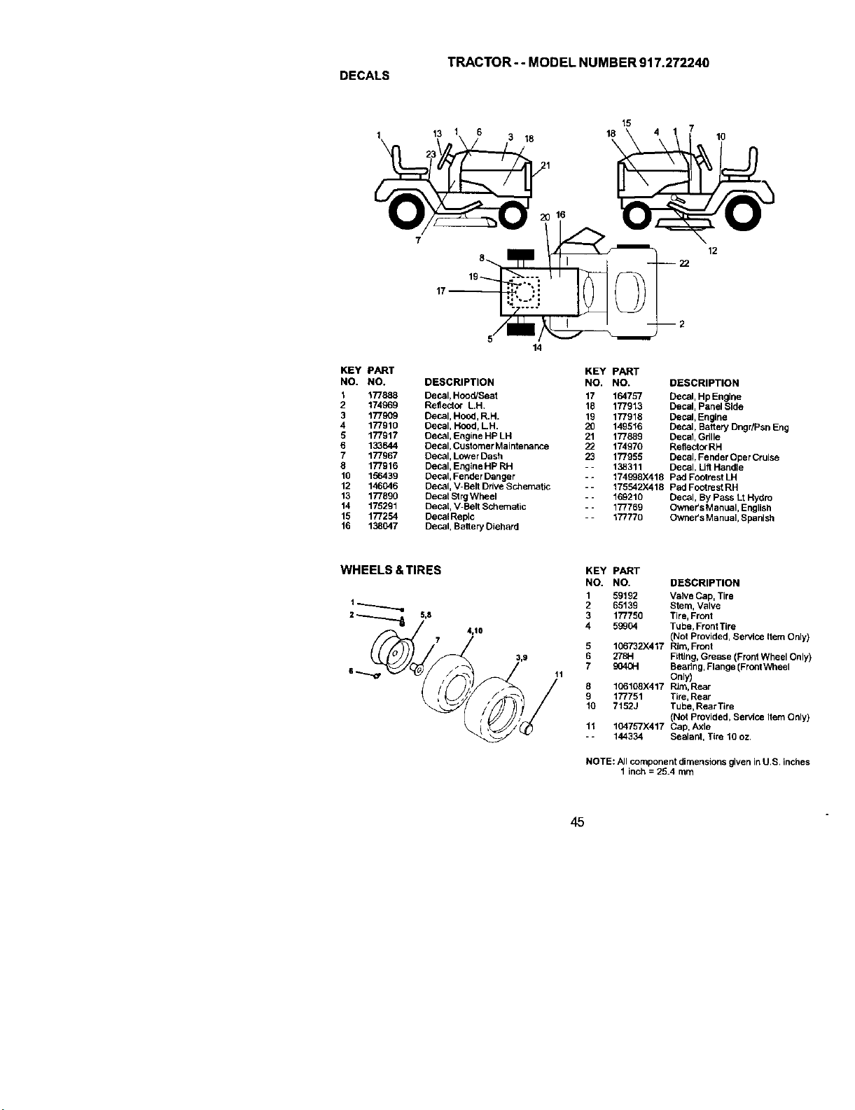
TRACTOR- - MODEL NUMBER 917.272240
DECALS
13
18
15
18
\
10
12
KEY PART
NO. NO.
1 177888
2 174969
3 177909
4 177910
5 177917
6 133644
7 177967
8 177916
16 156439
12 146046
13 177890
14 175291
15 177254
16 138047
14
DESCRIPTION
Decal, Hood/Seat
Reflector LH.
Decal, Hood, R.H.
Decal, Hood, LH.
Decal, Engine HP LH
Decal, Customer Maintenance
Decal, Lower Dash
Decal, EngineHP RH
Decal, Fender Danger
Decal, V-Belt Drive Schematic
Decal StrgWheel
Decal, V-Belt Schematic
DecalReplc
Decal, Battery Diehard
KEY PART
NO. NO. DESCRIPTION
17 164757 Decal, Hp Engine
18 177913 Decal, Panel Side
19 177916 Decal,Engine
20 149516 Decal, Battery Dngr/Psn Eng
21 177689 Decal, Grille
22 174970 Reflector RH
23 177955 Decal, Fender Oper Cruise
- - 138311 Decal, LiftHandle
- - 174998X418 Pad Footrest LH
-- 175542)(416 Pad Footrest RH
- - 169210 Decal, By Pass Lt Hydro
- - 177769 Owner's Manual, English
-- 177770 Owner's Manual, Spanish
4,10
11
KEY
NO.
1
2
3
4
8
9
10
11
PART
NO. DESCRIPTION
59192 Valve Cap, Tire
65139 Stem, Valve
177756 Tire, Front
59904 Tube, FrordTire
(Not Provided, Service Item Only)
106732)(417 Rim, Front
2781-1 Fitting, Grease (Front Wheel Only)
904(_ Bearing, Flange (Front Wheel
Only)
106108)(417 Rim, Rear
177751 Tire, Rear
7152J Tube, Rear Tire
(Not Provided, Service Item Only)
104757X417 Cap, Axle
144334 Sealant, Tire 10 oz.
NOTE: All component dimensions given inU,S. inches
1 inch = 25.4 mm
45
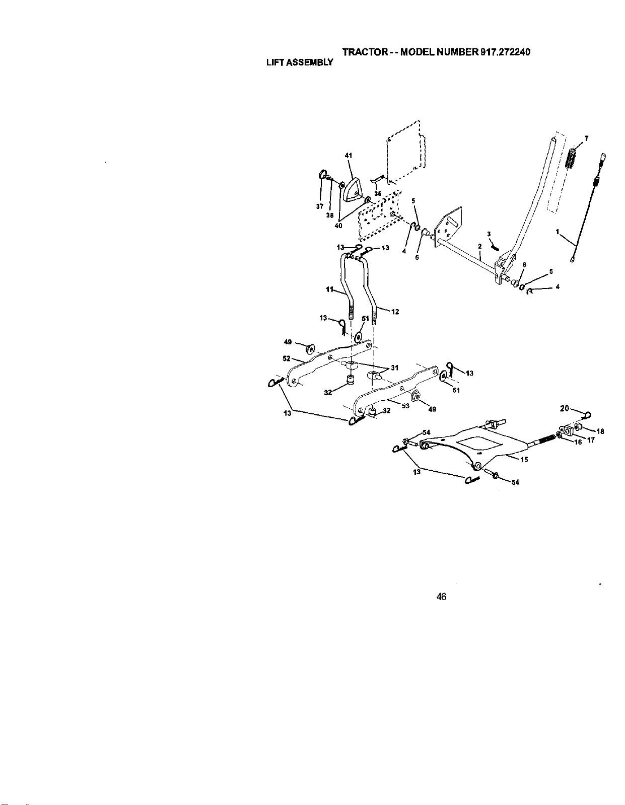
TRACTOR - - MODEL NUMBER 917.272240
LIFTASSEMBLY
54
46

TRACTOR-- MODEL NUMBER 917.272240
LIFTASSEMBLY
KEY PART
NO. NO. DESCRIPTION
1 176263 PlungerAssembly
2 159476 Shaft Assembly, Uft
3 138284 Pin, Groove
4 12000002 E-Ring
5 19211621 Washer 21/32 x 1 x 21 Gauge
6 120183X Bearing,Nylon
7 175830 Grip, Handle, Fluted
11 175370 Link, LJft, L.H.
12 175371 Link, Lift, R.H.
13 4939M RetainerSpdng
15 175562 Plate Asm Suspension Front
16 73350800 NutJam Hex 1/2-13 Unc
17 175689 Trunnion FrontSusp,
18 73800800 Nut Lock wfWsh 1/2-13 Unc
20 163552 Retainer Spring
31 176205 Trunion SLIps.Arm.
32 175994 Nut Uft Link 7/16-20
36 155097 pointer Height Indicat or
37 123935X Plug Hole
38 17066516 Screw 5/16-18 x 1
40 19112410 Washer 11132 x 1-1/2 x 10 Ga
41 155098 Indicator Height Silt
49 145212 Nut Hex/Large Lock
51 19171416 Washer 17/32 x 7/8 x 16 Ga.
52 175378 Arm Suspension Rear LH
53 175802 Arm Suspension Rear RH
54 175560 PInFlange
NOTE: All component dimensions given in U.S. inches
1 inch = 25.4 mm
47
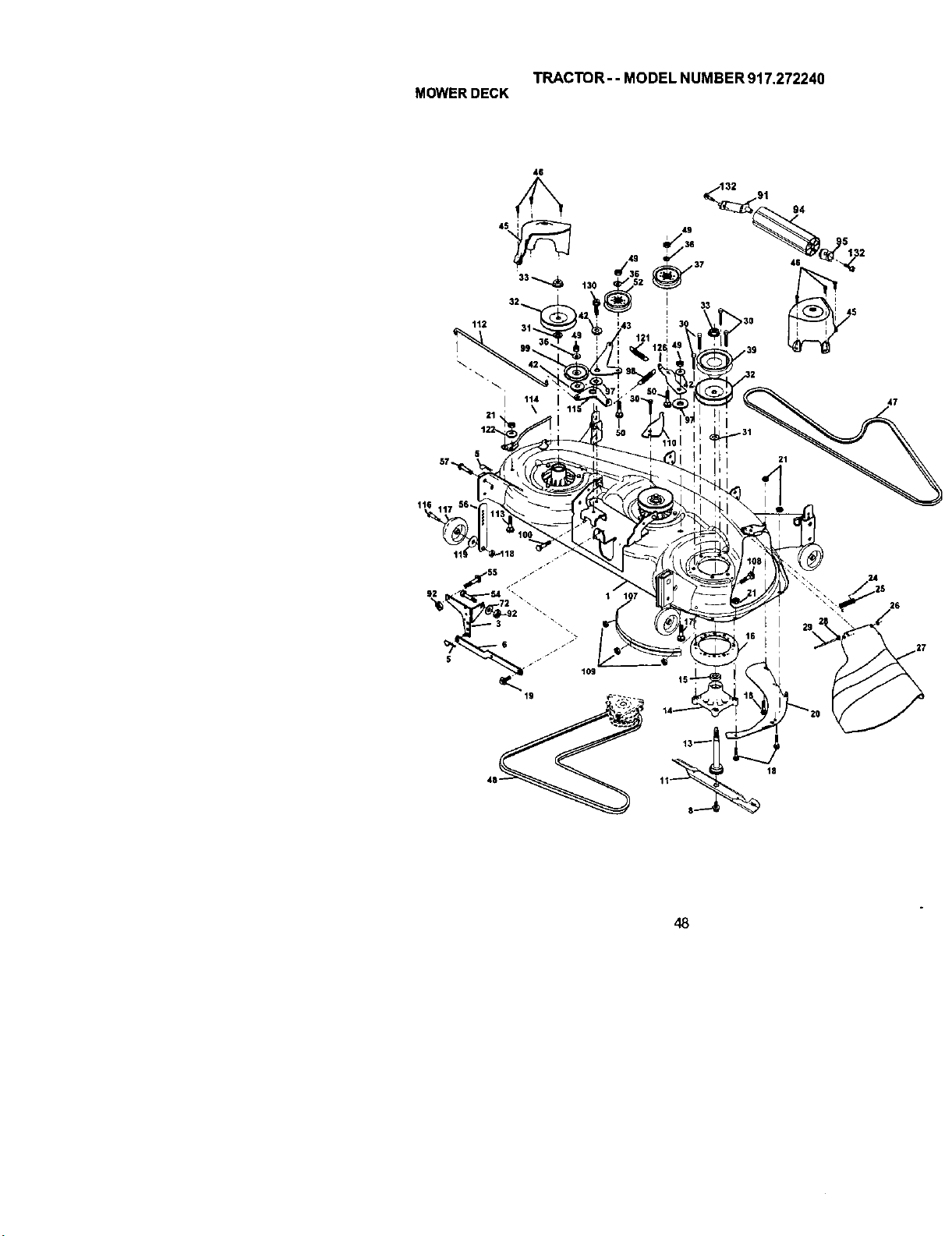
TRACTOR-- MODEL NUMBER 917.272240
MOWERDECK
46
112
47
1t6
18
26
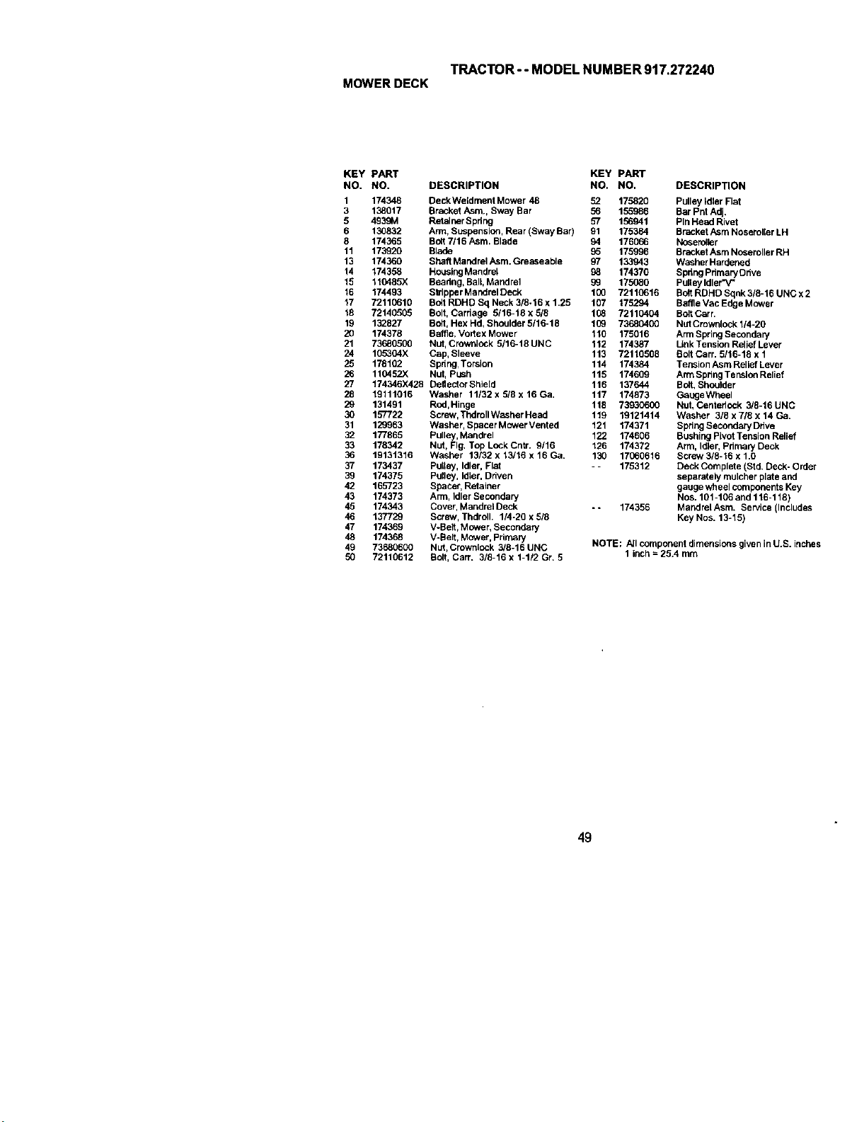
TRACTOR - - MODEL NUMBER 917.272240
MOWERDECK
KEY PART KEY PART
NO. NO. DESCRIPTION NO. NO. DESCRIPTION
1 174348 DeckWeldment Mower 48 52 175820 Pulley _dler Flat
3 138017 Bracket Asm., Sway Bar 56 155986 Bar Pnt Adj,
5 4939M Retainer Spdng 57 156941 Pin Head Rivet
6 130832 Arm, Suspension, Rear (Sway Bar) 91 175384 Bracket Asm Noseroller LH
8 174365 Bo6 7116 Asm. Blade 94 176066 Noseroller
11 173920 Blade 96 175996 Bracket Asm Noseroller RH
13 174360 Shelf Mandrel Asm. Greaseable 97 133943 Washer Hardened
14 174358 HousingMandrel 98 174370 Spdng PdmaryDdve
15 116485X Beadng, Ball Mandrel 99 175080 Pulley Idler'V'
16 174493 Stripper Mandrel Deck 100 72110616 Bolt RDHD Sqnk 3/8-16 UNC x 2
17 72110610 Bolt RDHD Sq Neck 3/8o16 x 1.25 107 175294 BaffleVac Edge Mower
18 72140505 Bolt, Carriage 5116-18 x 5/8 108 72110404 Bolt Cart,
19 132827 Bolt, Hex Hd, Shc_Jlder5/16-18 109 73680400 NutCrownlock 1/4-20
20 174378 Baffle, Vortex Mower 110 175016 Arm SpringSecondary
21 73680500 Nut, Crownlock 5/16-18UNC 112 174387 UnkTensionReliefLever
24 105304X Cap, Sleeve 113 72110508 Bolt Carr. 5/16-18 x 1
25 178102 Spdng, Torslon 114 174384 Tension Asm Relief Lever
26 110452X Nut, push 115 174609 ArmSpringTensionRelief
27 174346X428 DellectorShie[d 116 137644 Bolt, Shoulder
28 19111016 Washer 11132 x 518 x 16 Ga. 117 174873 GaugeWheel
29 131491 Rod,Hinge 118 73930600 Nut, Cerderlock 3/8-16UNC
30 157722 Screw, ThdmllWasher Head 119 19121414 Washer 3/8 x 7/8 x 14 Ga.
31 129963 Washer, Spacer Mower Ventad 121 174371 Spring Secondary Ddve
32 177865 Pulley, Mandrel 122 174606 Bushing Pivot Tension Relief
33 178342 Nut, Fig, Top Lock Cntr. 9/16 126 174372 Arm, Idler, Pdrnary Deck
36 19131316 Washer 13/32 x 13/16 x 16 Ga. 130 17(;60616 Screw 3/8-16 x 1.0
37 173437 PuLtey,Idler, Flat - - 175312 Deck Complete (S/d, Deck- Order
39 174375 Pulley, IdLer,Driven separately mulcher plate and
42 165723 Spacer, Retainer gauge wheel comgenents Key
43 174373 Arm, Idler Secondary Nos. 101-106 and 116-118)
45 174343 Cover, Mandrel Deck - - 174356 Mandrel Asm, Service (Includes
46 137729 Screw, Fhdroll, 1/4-20 x 5/8 Key Nos. 13-15)
47 174369 V-Belt, Mower, Secondary
48 174368 V-Belt, Mower, Primary
49 73680600 Nut_Crownlock 3/8-16 UNC NOTE; A!lcomponent dimensions given in U.S. inches
50 72110612 Bolt, Cart. 3/8-16 x 1-112 Gr. 5 1 inch = 25A mm
49
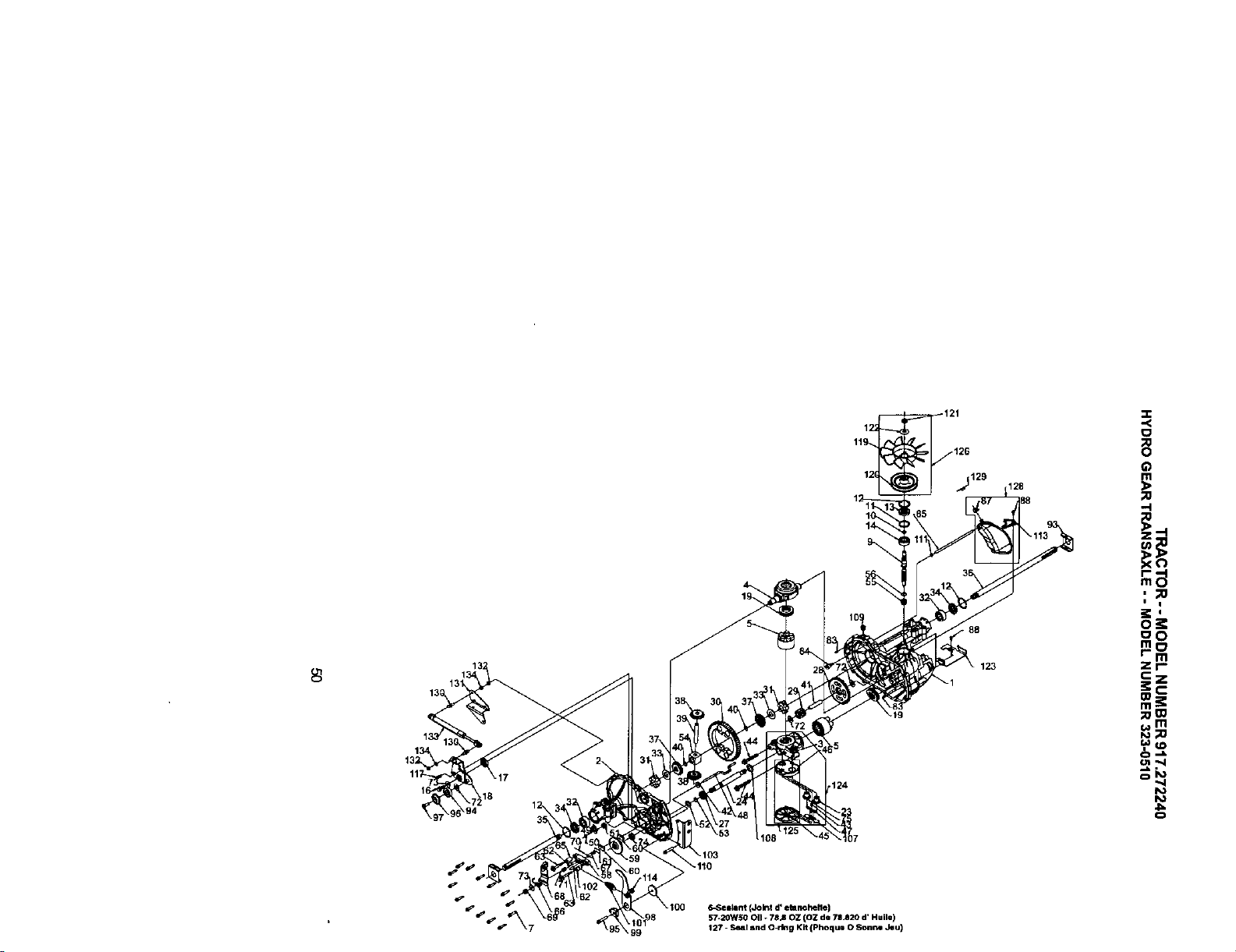
8
x.19
124
_129
88
123
128
,.<
0
m
-4
,,;oe
o:e
oo
mo
r- m
zr-
cZ
m_
m
_m
0,,,_
"4
0
6-Selllant (Join! d' etlnchefle)
57-20W50 OU - 7SJ OZ (OZ de 78J20 d' Huile)
127 - Seal and O_mg Kit (Phoquo 0 So.he Jeu)
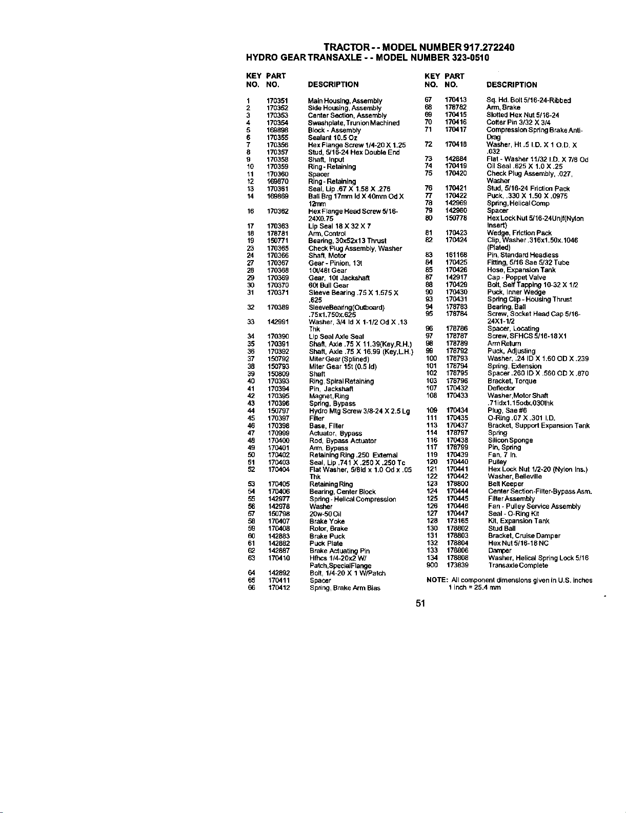
TRACTOR-- MODEL NUMBER 917.272240
HYDROGEARTRANSAXLE- - MODELNUMBER323-0510
KEY PART KEY PART
NO, NO, DESCRIPTION NO. NO. DESCRIPTION
1 170351 Main Housiug, Assembly 67 170413 Sq, Hd. Bolt 5!16-24-Ribbed
2 170352 Side Housing, Assembly 68 178782 Arm, Brake
3 170353 Center Section, Assembly 69 170415 Slotted Hex Hut 9/16-24
4 170354 Swashplate,Trunion Machined 70 170416 CoSer Pin 3/32 X 314
9 150896 Block * Assembly 71 170417 Compression Spring Brake Anti-
6 170399 Sealant 10,50z Drag
7 170356 Hex Flange Screw 1/4-20 X 1.25 72 170418 Washer, Ht .5 I.D. X 10.D, X
8 170357 Stud, 5/16-24 Hex Double End ,032
9 170358 Shaft, Input 73 142884 Flat - Washer 11132 I.D. X 718Od
10 170359 Ring- Retaining 74 170419 Oil Seal .625 X 1,0 X .25
11 170360 Spacer 76 170420 Check Plug Assembly, .027,
12 169870 Ring - Retaining Washer
13 170361 Seal, Lip .67 X 1,58 X .276 76 170421 Stud, 5/16o24 Fdction Pack
14 169869 Bat[ Brg 17ram Id X 40ram Od X 77 170422 puck, .330 X 1.50 X .0975
12ram 76 142969 Spdng,HeUcalComp
16 170362 Hex Flauge Head Screw 5/16- 79 142980 Spacer
24)(0.75 80 150778 Hex Lock Nut 5/16*24Unjf(Nylon
17 170363 Lip Seal 18 X 32 X 7 insert)
18 178781 Arm, Control 81 170423 Wedge, Fdction pBx_k
19 150771 Beadng, 30x92x13 Thruat 82 170424 Clip,Washer .316x1.50x.1046
23 170365 Check Plug Assembly, Washer (Plated)
24 170366 Shaft, Motor 83 161166 Pin, Standerd HeadLess
27 170367 Gear - Pinion, 13t 84 170425 Fitting, 5/16 Sae 5132 Tube
28 170368 10t/48t Gear 85 170426 Hose, Expansion Tank
29 170369 Gear, 1OtJackshaft 87 142917 Cap - Poppet Valve
30 170370 60t Bull Gear 50 170429 Bolt, Self Tapping 10-32 X 1/2
31 170371 Sleeve Bearing .75 X 1.575 X 90 176430 Puck, Inner Wedge
.625 93 170431 Spring CUp- HousingThrust
32 170389 SleeveBeadug(Octboard) 94 178783 Beadng, Ball
.75xl.750x.625 95 178784 Screw, Socket Head Cap 5/16-
33 142991 Washer, 3/4 Id X 1-1/2 Od X .13 24X1-1/2
Thk 96 178786 Spacer, Locating
34 170390 LipSeal Axle Seol 97 178787 Screw, SFHCS 5/16-18 X1
35 170391 Shaft, Axle .75 X 11.39(Key,R,H.) 98 178789 ArmReturn
36 170392 Shaft, Axle .75 X 16.99 (Key,LH.) 50 178792 Puck, Adjusting
37 150792 MiterGear(Spfined) 100 178793 Washer, .24 ID X 1.60 OD X .239
50 150793 Miter Gear 15t (0.5 Id) 101 178794 Spdng, Extension
39 150809 Shall 102 178795 Spacer .260 ID X .560 OD X .870
40 170393 Ring, SpiralRetainlng 103 178796 Bracket, Torque
41 170394 Pin, Jackshafl 107 170432 Deflector
42 170395 Magnet,Ring 108 170433 Washer,Motor Shaft
43 170396 Spring, Bypass .71idx1.19od_.O30thk
44 150797 Hydro Mtg Screw 3/8-24 X 2.5 Lg 109 170434 Plug, Sae #6
45 170397 Filter 111 170435 O-Ring .07 X .301 I.D.
46 170398 Base, Filter 113 170437 Bracket, Support Expansion Tank
47 170999 Actuator, Byp_s 114 178797 Spnng
48 170400 Rod, Bypass Actuator 116 170438 SiliconSponge
49 170401 An*n,Bypass 117 178799 Pin,Spdng
50 170402 Retaining Ring .250 External 119 170439 Fan, 7 In.
51 170403 Seal, Lip .741 X .290 X .250 Tc 120 170440 Pufley
52 170404 Flat Washer, 5181dx 1.OOd x .05 121 170441 Hex Lock Nut 1/2-20 (Nylon Ins,)
Thk 122 170442 Washer, Belleville
53 170405 ReutiolngRing 123 178800 Belt Keeper
54 170406 Beadng, Center Block 124 170444 Center Section-Filter-Bypass Asm.
55 142977 Spring*Helical Compression 125 170449 Filtar Assembly
56 142978 Washer 126 170446 Fan - Pulley Service Assembly
57 150798 20w-50Oil 127 170447 Seal - O-Riug Kit
50 170497 Brake Yoke 128 173165 Kit, Expansion Tank
59 170408 Rotor, Brake 130 178802 Stud Ball
60 142883 Brake Puck 131 178803 Bracket, Cruise Damper
61 142882 Puck plate 132 178804 HexNut 5/16-18 NC
I_ 142887 Brake Actuating Pin 133 176806 Damper
63 170410 Hthcs 114-20:<2W/ 134 178808 Washer, Helical Spring Lock 5/16
Patch,SpecialFlauge 900 173839 Transaxle Completa
64 142892 Bolt, 1/4-20 X 1 W/Patch
65 170411 Spacer NOTE: AJlcomponent dimensions given in U.S. inches
66 170412 Spnng, Brake Arm Bias t inch = 25.4 mm
51
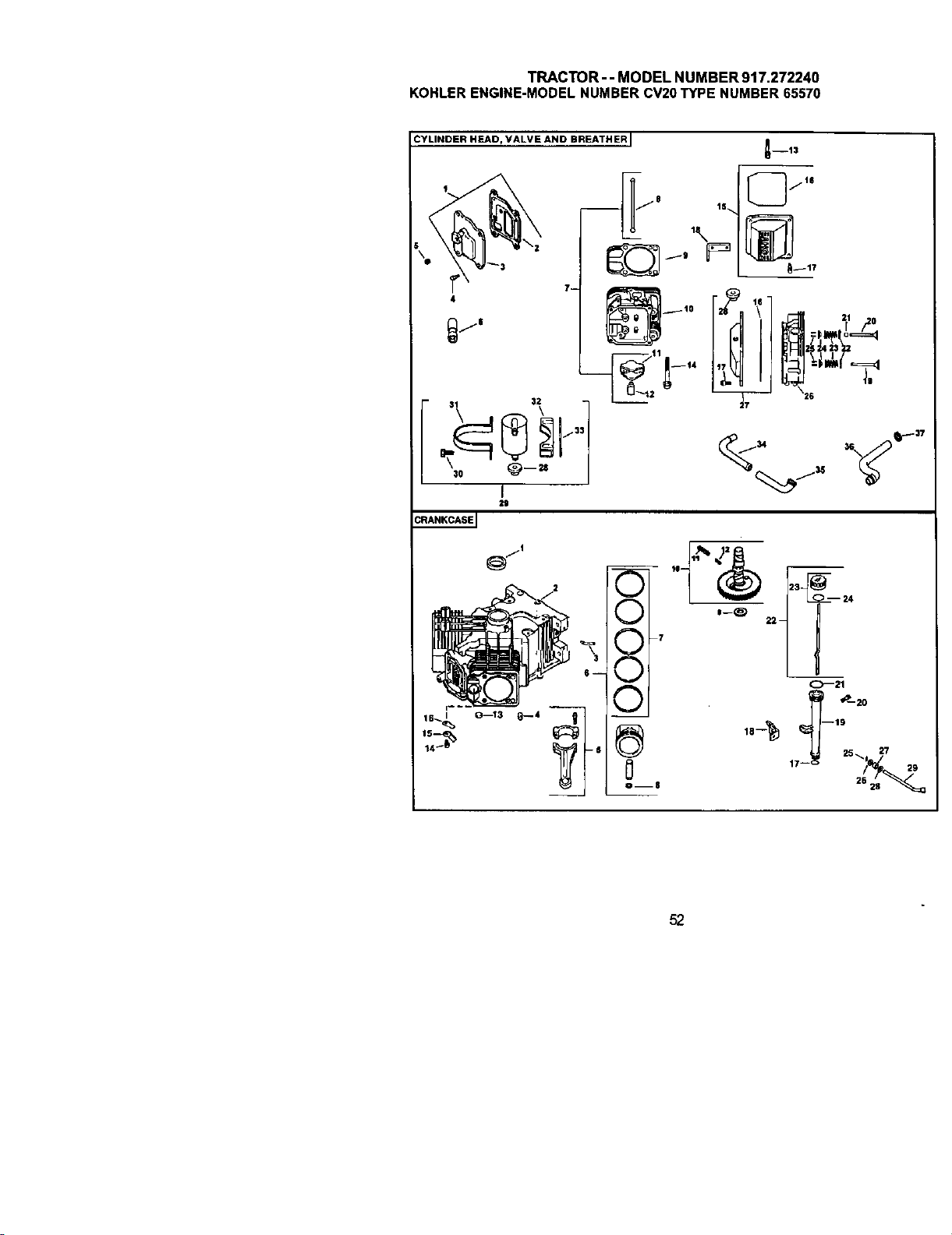
TRACTOR--MODELNUMBER917.272240
KOHLERENGINE-MODELNUMBERCV20TYPENUMBER65570
CYLINDER HEAD, VALVE AND BREATHER I
_--13
14 _&
t-ft I7-
3 24
I--_ 22 --
T
I o--21
25 _ 27
52
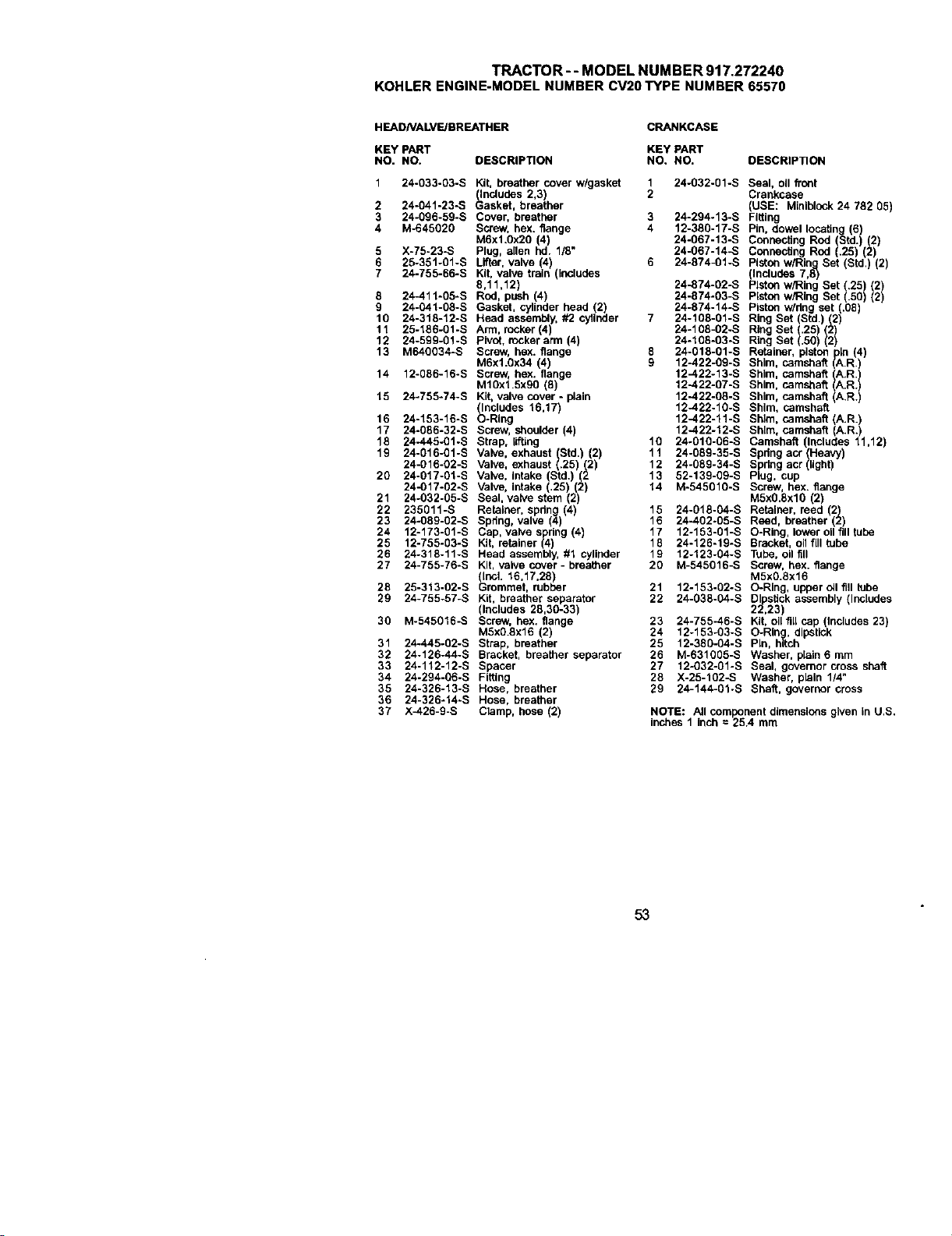
TRACTOR - - MODEL NUMBER 917.272240
KOHLERENGINE-MODELNUMBERCV2OTYPE NUMBER65570
HEADNALVE/BREATHER CRANKCASE
KEY PART KEY PART
NO. NO. DESCRIPTION NO. NO. DESCRIP_ON
1 24-033-03-S Kit, breather cover w/gasket 1 24-032-01-S Seal, oil front
(includes 2,3) 2 Crankcase
2 24-041-23-S Gasket, breather (USE: Miniblcck 24 782 05)
3 24-096-59-S Cover, breather 3 24-294.13-S Fitting
4 M-645020 Screw, hex. flange 4 12-380-17-S Pin, dowel locating (6)
M6xl.Ox20 (4) 24-g67-13-S Connecting Rod (Std.) (2)
5 X-75-23-S Plug, allen hd. 1/8" 24-067-14-S Connecting Rod (.25) (2)
6 25-351-gl-S Lifter, valve 4 6 24-874-01-S Piston w/Ring Set (Std,) (2)
7 24-755-66-S Kt, vave ran ndudes (includes 7,8)
8,11,12) 24-874-02-S Piston w/Ring Set (.25 (2)
8 24-411-05-S Rod, push (4) 24-874-03-S Pston w/Rng Set .50 2
9 24-041-08-S Gasket, cylinder head (2) 24-874-14-S Piston w/dng set (.08)
10 24-318-12-S Head assembly, #2 cyflnder 7 24-108-01-S Ring Set (Std,) (2)
11 25-186-gl-S Arm, rocker(4) 24-108-02-S Ring Set (,28) (2)
12 24-599-01-S Pivot. rocker arm (4) 24-108-03-S Ring Set (.5g) (2)
13 M64g034-S Screw, hex. flange 8 24-018-01-S Retainer, piston p_n (4)
M6x1.Ox34 (4) 9 12-422-0g-s Shim, camshaft (A,R,)
14 12-086-16-S Screw, hex. flange 12-422-13-S Shim, camshaft (A.R)
Mlgxl,5xgg (8) 12-422-07-S Shim, camshaft ()A.R.
15 24-755-74-S Kit, valve cover - plain 12-422-08-S Shim, camshaft (A.R.)
(Includes 16,17) 12-422-10-S Shim, camshaft
16 24-153-16-S O-Ring 12--422-11-S Shim, camshaft (A.R.)
17 24-g86-32-S Screw, shoulder (4) 12-422-12-S Shim, camshaft (A.R.)
18 24-445-01-S Strap, lifting 10 24-010-06-S Camshaft (Includes 11,12)
19 24-016-01-S Valve, exhaust (Std. 2 11 24-089-35-S Spring act (Heavy)
24-016-02-S Valve, exhaust (.25) (2 12 24-089-34-S Spdng acr (_ight)
20 24-017-01-S Valve, Intake (Std.) (2 13 52-139-g9-s Plug, cup
24-017-02-S Valve, intake ,25) (2) 14 M-545010-S Screw, hex. flange
21 24-032-05-S Seal, valve stem 2) M5xO.8xl0 (2)
22 235011-S Retainer, spdng (4) 15 24-018-04-S Retainer, reed 2)
23 24-089-02-S Spdeg, valve (4) 16 24-402-05-S Reed, breather 2
24 12-173-01-S Cap, valve spring (4) 17 12-153-01-S O-Ring, lower oil fill tube
25 12-755-03-S Kit, retainer (4) 18 24-126-19-S Bracket, oil fill tube
26 24-318-11-S Head assembly, #1 cylinder 19 12-123-04-S Tube, oil fill
27 24-755-76-S Kit, valve cover- breather 20 M-545016-S Screw, hex. flange
(Incl. 16,17,28) M5xg.8x16
28 25-313-02-S Grommet, rubber 21 12-153-02-S O-Ring, upper _1 fig tube
DI stick assembly (Includes
29 24-755-57-S Kit,(includesbreather28,30.33)separator22 24-g38-04-S 21P23)2,
30 M-545016-S Screw, hex. flange 23 24-755-46-S Kit, oil fill cap (Includes 23)
MSxO.8x16 (2) 24 12-153-g3-s O-Ring, dipstick
31 24-445-02-S Strap, breather 25 12-38g-o4-s Pin, hitch
32 24-126-44-S Bracket, breather separator 26 M-631005-S Washer, plain 6 mm
33 24-112-12-S Spacer 27 12-032-01-S Seal, governor cross shaft
34 24-294-g6-s Fitting 28 X-25-102-S Washer, plain 1/4"
35 24-326-13-S Hose, breather 29 24-144-01-S Shaft, governor cross
38 24-326-14-S Hose, breather
37 X_26-9-S Clamp, hose (2) NOTE: All component dimensions given in U,S.
inches 1 inch = 25.4 mm
53
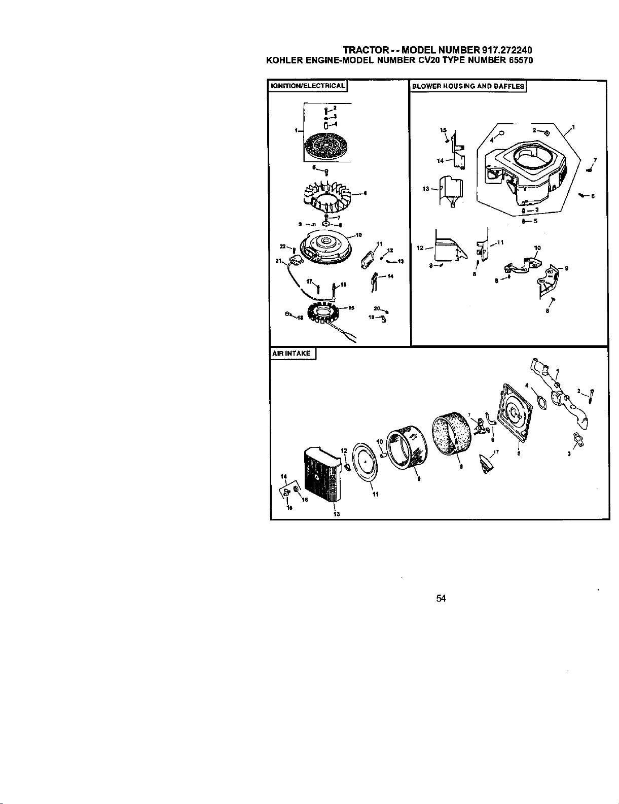
TRACTOR--MODELNUMBER917.272240
KOHLERENGINE-MODELNUMBERCV20TYPENUMBER65570
IGNITtONIELECTRICAL
AIR INTAKE J
BLOWER HOUSING AND BAFFLES I
14 j
13_
O---S
_fll 10
8
/.1
\
_1 11 g
13
54
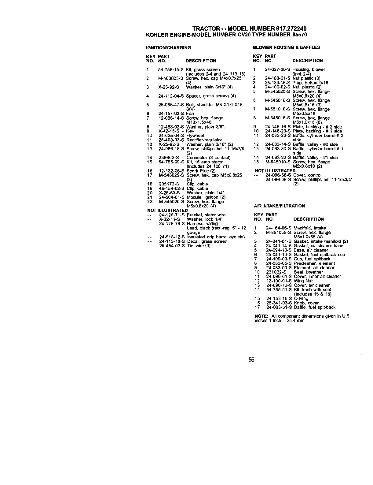
TRACTOR- - MODEL NUMBER 917.272240
KOHLERENGINE-MODELNUMBERCV20TYPE NUMBER65570
IGNITIONICHARGING
BLOWER HOUSING & BAFFLES
KEY PART KEY PART
NO. NO, DESCRIPTION NO, NO, DESCRIPTION
1 54-755-15-S Kit, grass screen 1 24-027-20-S Housing, blower
(Includes 2-4,and 24 113 18) Incl. 2-4)
2 M-403925-S Screw, hex. cap M4x0 7x26 2 24-100-01-S Nut plaslJc 3
(4) 3 25-139-16-S Plug, button 9116
3 X-25-92-S Washer, plain 5/16" (4) 4 24-109-02-S Nut, plastic (2)
5 M-545029-S Screw, hex. flange
4 24-112-04-S Spacer, grass screen (4) M5x0.Sx20 (4)
6 M-545016-S Screw, hex. flange
5 25-086-47-S Bolt, shoulder M6 XI.0 X16 M5xO.8x16 (3)
S(4) 7 M-551016-S Screw, hex. flange
6 24-157-03-S Fan M5x0.8x16
7 12-086-14-S Screw, hex. flange 8 M-646616-S Screw, hex. flange
M10x1.5x46 M6x1.0x16 (6)
8 12-468-03-S Washer, plala 3/8". 9 24-146-16-S Plate, backing - # 2 side
9 X-42-15-S - Key 10 24-146-20-S Plate, backing - # 1 side
10 24-025-04-S Flywheel 11 24-063-20-S Baffle, cylinder barrel-# 2
11 25-403-03-S Rectifier.regulator side
12 X-25-92-S Washer. plain 3/16" (2) 12 24-063-14-S Baffle, valley - #2 side
13 24-086-18-S Screw, phtilip_ hd. 11-16x7/9 13 24-063-30-S Baffle, cylinder barreh# 1
(2) side
14 236692-S Connector (3 contact) 14 24-063-23-S Baffle, valley - #1 side
16 54-766-09-S Kit, 16 amlp stator 15 M-545010-S Screw, hex. flange
(Includes 24 126 71) MSxO.6xlO (2)
16 f2-f32-06-S Sl:_rk Plug (2) NOT ILLUSTRATED
17 M-548025-S Screw. hex. cap M5x0.flx25 -- 24-096-66-S Cover, control
(2) -- 24-086-06-S Screw, phillips hd. 11-16x3/4"
16 235173-S Clip, cable (2)
19 48-154-02-S Ctlp, cable
20 X-25-63-S Washer, plain 114"
21 24-584-01-S Module. Ignition (2)
22 M-546020-S Screw, hex. flange
M5xO.8x20 (4) AIR INTAKE/FILTRATION
NOT ILLUSTRATED
-- 24-126-71-S Bracket, stator wire KEY PART
-- X-22-11-S Washer, lock 1/4" NO. NO. DESCRIPTION
-- 24-176-79-S Harness, wiring
Lead, black (rect.-reg. 5" - 12 1 24-164-06-S Manifold, Intake
gauge 2 M-651055-S Screw, hex. flange
-- 24-518-12-S Insulated grip barrel eyelets) M6x1.0x55 (4)
-- 24-113-18-S Decal. grass screen 3 24-041-01-S Gasket, intake manifold (2)
-- 25-454-03-S Tie, wire (3) 4 24-041-14-S Gasket, air cleaner base
5 24-094-18-S Base, air cleaner
6 24-041-13-S Gasket, fuel spitback cup
7 24-169-09-S Cup, fuel spifback
8 24-083-05-B Precleaner, element
9 24-083-03-S Element, air cleaner
10 231032-S Seal, breather
11 24-096-01-S Cover, inner air c_eaner
12 12-100-01-S Wing Nut
13 24-096-73-S Cover, air cleaner
14 54-755-01-S Kit, knob with seal
(Includes 15 & 16)
15 24-153-15-S O-Ring
16 25-341-03-S Knob, cover
17 24-063-51-S Baffle, fuel spit-back
NOTE: All component dimensions given in U,S.
inches 1 inch = 25,4 mm
55
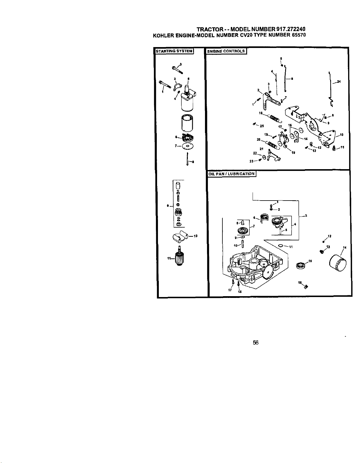
TRACTOR-- MODEL NUMBER 917.272240
KOHLERENGINE-MODELNUMBERCV20TYPE NUMBER65570
STARTING SYSTEM I
2 6
T-Q
0
!
S-- Q
oo
ENGINE CONTROLS
S
I
Qi
4 !
3 124
t6_ ills
01L PAN / LUBRICATION I
Q--2
56
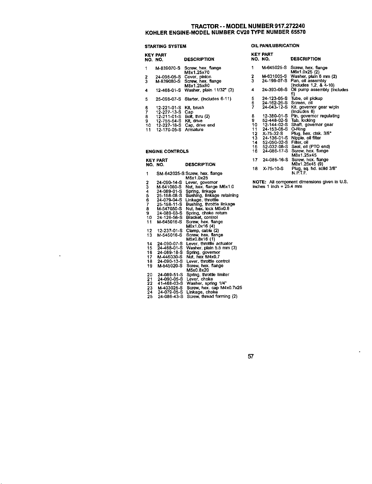
TRACTOR- - MODEL NUMBER 917.272240
KOHLERENGINE-MODELNUMBERCV20TYPE NUMBER65570
STARTING SYSTEM
OIL PAN/LUBRICATION
KEY PART KEY PART
NO, NO. DESCRIPTION NO. NO. DESCRIPTION
1 M-83go70-S Screw, hex. flange 1 M-645025-S Screw, hex. flange
MSx1.25X70 M6x1.0x25 (2)
2 24-096-05-S Cover, pinion 2 M-631005-S Washer, plain 6 mm (2)
3 M-839080-S Screw, hex. flange 3 24-199-07-S Pan, oil assembly
MSx1.25XS0 (Includes 1,2, & 4-10)
4 12-468-01-S Washer, plain 11132" (3) 4 24-393-08-S Oil pump assembly (Includes
5)
5 25-098-07-S Starter, (Includes 6-11) 5 24-123-05-S Tube, oil plokup
6 24-162-26-B Screen, oil
6 12-221-01-S Kit, brush 7 24-043-12-S Kit, governor gear wlpin
7 12-227-13-S Cap (Includes 8)
8 12-211-01-S Bolt, thru (2) 8 12-380-01-S Pin, governor regulating
9 12-755-54-S Kit, drive g 52-448-02-S Tab, locking
10 12-227-18-S Cap, drive end 10 12-144-02-S Shaft, governor gear
11 12-170-05-S Armature 11 24-153-08-S O-Rthg
12 X-75-32-S Plug, hex. ctsk. 3/8"
13 24-136-01-S Nipple, oil filter
14 52-050-02-S Filter, oil
15 52-032-08-S Seal, oll (PTO end)
ENGINE CONTROLS 16 24-086-17-S Screw, hex. flange
MSx1.25x45
KEY PART 17 24-086-16-S Screw, hex. flange
NO. NO. DESCRIPTION MSx1.25x45 (9)
18 X-75-10-S Plug, sq. hd. solid 3/8"
1 SM-642025-S Screw, hex. flange N.P.T.R
M6x1.0x25
2 24-090-14-S Lever. governor NOTE: An component dimensions given in U,S.
3 M-641060-S Nut, hex. flange M6xl.0 inches 1 inch = 25.4 mm
4 24-089-01-S Spring, linkage
5 25-158-08-S Bushing, linkage retaining
6 24-079-O4-S Linkage, throttle
7 25-158-11÷S Bushing, throttle linkage
8 M-547050-S Nut, hex. lock M5x0.8
9 24-089-03-S Spdng, choke return
10 24-126-56-S Bracket, control
11 M-645016-S Screw, hex. flange
M6x1.0x16 (4)
12 12-237-01-S Clamp, cable (2)
13 M-545016-S Screw, hex. flange
M5xO.Sx16 (1)
14 24-090-07-S Lever, throttle actuator
15 24-468-01-S Washer, plain 5.5 mm (3)
16 24-089-18-S Spring, governor
17 M-446030-S Nut, hex M4x0.7
18 24-090-13-S Lever, throttle control
19 M-545020-S Screw, hex. flange
MSx0,8x2O
20 24-089-51-S Spdng, throifla limiter
21 24-090-05-S Lever, choke
22 41-468-03-S Washer, spdng 1/4"
23 M-403025-S Screw, hex. cap M4xO,Tx25
24 24-079-05-S Linkage, choke
25 24-086_3-S Screw, thread forming (2)
57
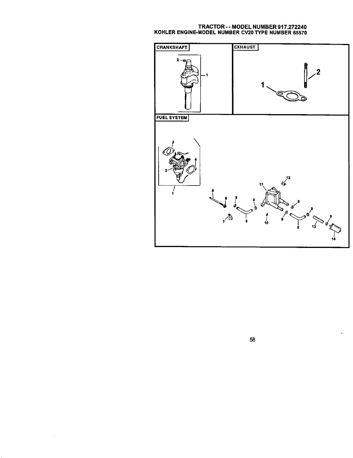
TRACTOR- - MODEL NUMBER 917.272240
KOHLERENGINE-MODELNUMBERCV20TYPE NUMBER65570
CRANKSHAFT J
2--_ --1
EXHAUSTJ
1
_j2
FUEL SYSTEM I
/
F
t4
58
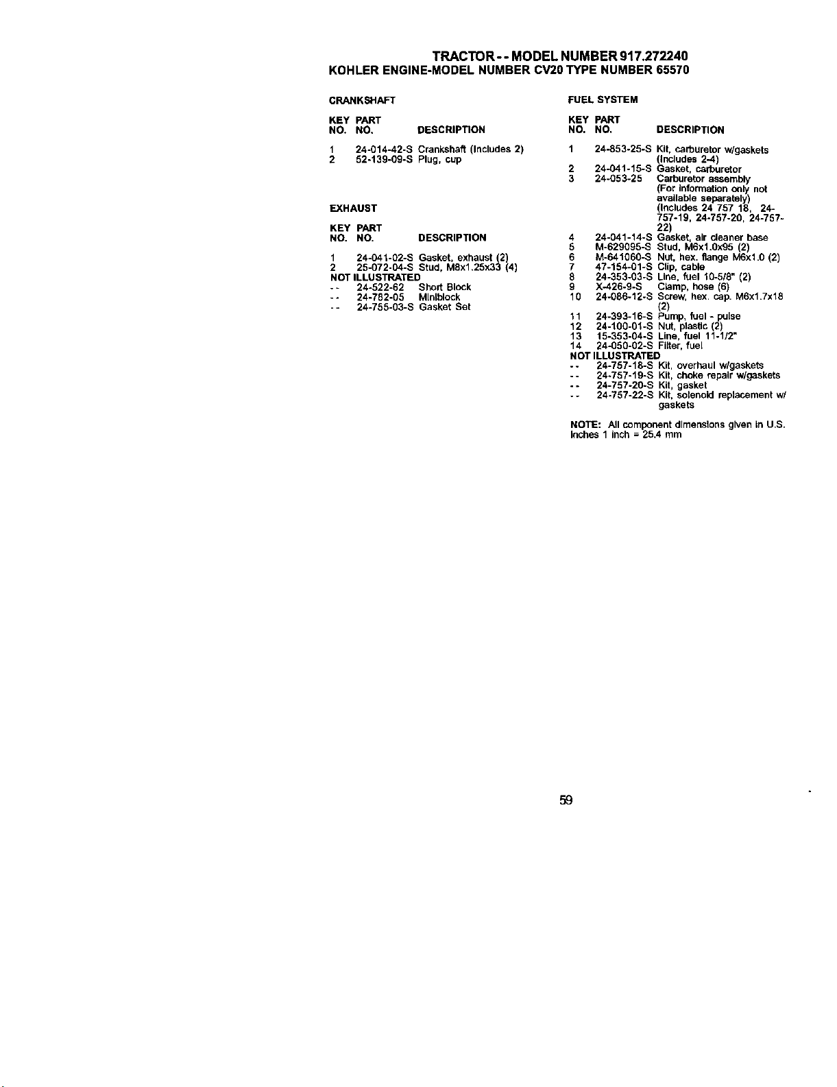
TRACTOR--MODELNUMBER917.272240
KOHLERENGINE-MODELNUMBERCV20TYPENUMBER65570
CRANKSHAFT FUEL SYSTEM
KEY PART KEY PART
NO. NO. DESCRIPTION NO, NO,
1 24-014-42-S Crankshaft (Includes 2) 1 24-853-25-S
2 52-139-69-S Plug, cup
2 24-041-15-S
3 24-053-25
EXHAUST
KEY PART
NO. NO. DESCRIPTION
1 24-041-02-S Gasket, exhaust (2)
2 25-072-04-S Stud, M8x1.25x33 (4)
NOT ILLUSTRATED
-= 24-522-62 Short Block
- - 24-782-65 MInIblock
-- 24-755-63-S Gasket Set
DESCRIPTION
Kit, carburetor w/gaskets
(InCludes 2-4)
Gasket, carburetor
Carburetor assembly
(For information o_ly not
available separately)
(Includes 24 757 18, 24-
757-19, 24-757-20, 24-757-
22)
4 24-041-14-S Gasket, air cleaner base
5 M-629695-S Stud, M6x1.Ox95 (2)
6 M-641060-S Nut, hex. flange M6x1.0 (2)
7 47-154_01-S Clip, cable
8 24-353-03-S Line, fuel 10-518" (2)
9 X-426-9-S Cbmp, hose (6)
10 24-086-12-S Screw, hex, cap. MSx1.7x18
(2)
11 24-393-16-S Pump, fuel - pulse
12 24-100-01-S Nut, plasBc (2)
13 15-353-04-S Line, fuel 11-1/2"
14 24-050-02-S Fi_ter, fuel
NOT ILLUSTRATED
-- 24-757-16-S Kit, overhaul wlgaskets
-- 24-757-19-S Kit, choke repair w/gaskets
-- 24-757-20-S Kit, gasket
- - 24-757-22-S Kit, solenoid replacement w/
gaskets
NOTE: All component dimensions given In U,S.
Inches 1 Inch = 25.4 mm
59


61

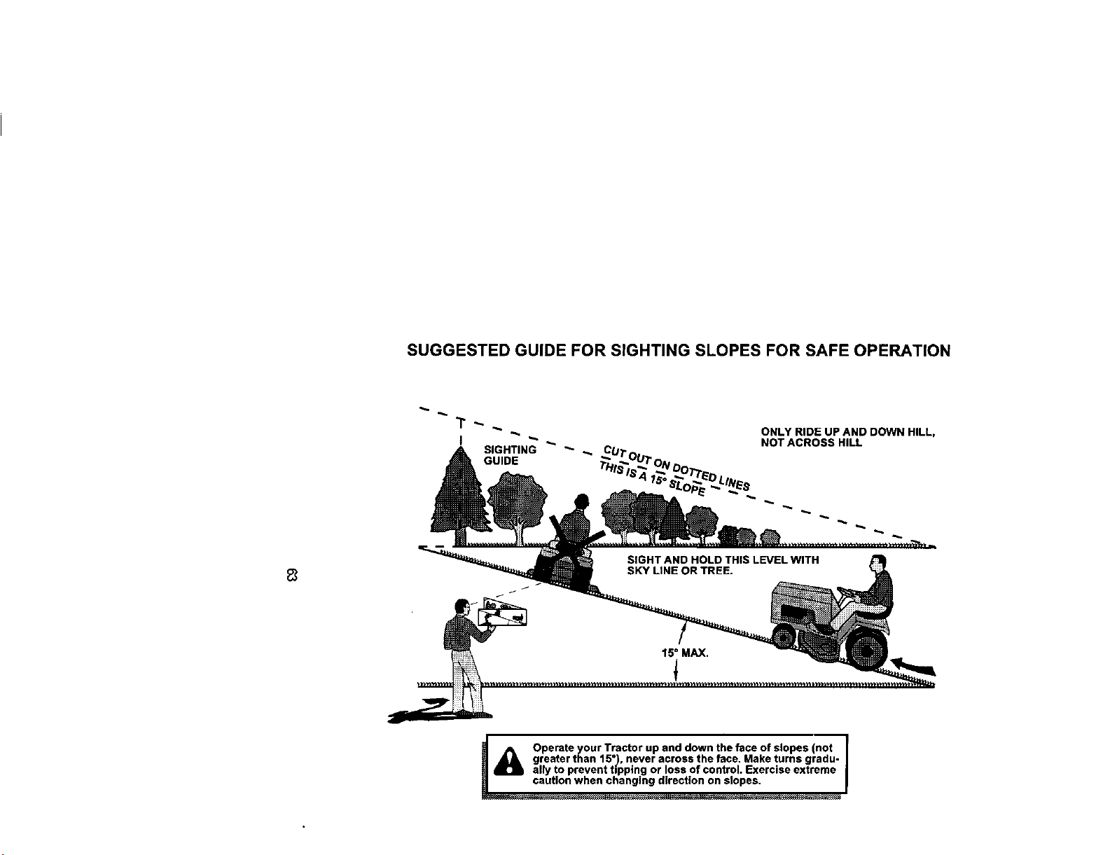
SUGGESTED GUIDE FOR SIGHTING SLOPES FOR SAFE OPERATION
SIGHTING _ _ _.CUT"I
GUIDE
ONLY RIDE UP AND DOWN HILL,
NOT ACROSS HILL
_/_ erate your Tractor up and down the face of slopes (not
greater than 15°), never across the face. Make turns gradu-
ally to prevent tipping or loss of control. Exercise extrame
Forrepairofmajorbrandappliancesin yourown home...
nomatterwhomadeit,no matterwhosoldit!
For repairofcarry-inproductslikevacuums,lawnequipment,and
electronics,callforthenearestSearsPartsand RepairCenter.
1-800-488-1222 Any'a_e,dayor_ght(U.S.A.ody)
I_aNw.sear_,o0rn
Forthereplacementparts,accessoriesandowner'smanuals
thatyouneedtodo-it-yourself,callSearsPartsDirectSM!
1-800-366-PART
(1-800-366-7278)
6a.m.-11p.m.,7daysaweek
(u.s,_ m_,}
w_irect
To purchaseorinquireabouta SearsServiceAgreement
orSearsMaintenanceAgreement:
1-800-827-6655 (u.s._)
1-800-361-6665 (Canada)
7 &m. - 5p.m.,CST,MorL- SaL 9a.m.- 8 p.m.EST, M- F,4p.m.SaL
Patapedrserviciode mparacidna AuCanadapourser_ceenfrar_
derniclo,ypareordenarpieza_ 1.8(X).LE.FOYERUC
1"888-SU'HQGAR_ (14Y)0-&33-693_
_, (14_-784-6427) wry,sears.ca
H°meCer l®J
® Registered Trademark I "n_Trademark I sMService Mark of Sears, Roebuck and Co.
® Marca Regtstrada / "r_Marca de Fdbdca / s_ Mama de Servicio de Sears, Roebuck and Co.
MCMarque de commerce / M_Marque ddposfJede Seam, Roebuck and Co.
o
177769 Rev.1 2.16.01 TR PdntedinU.S.A.


