
Loading ...
Loading ...
Loading ...
23
Owner’s Manual
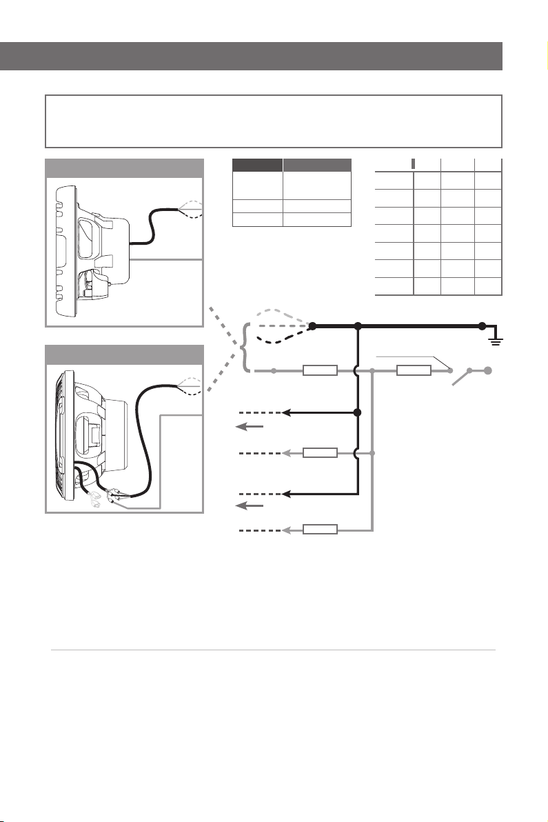
FUSE
FUSE
FUSE
FUSE
RED
RED
RED
GREEN
GREEN
GREEN
BLUE
BLUE
BLUE
YELLOW
(+ 12 V)
YELLOW
(+ 12 V)
YELLOW
(+ 12 V)
+ 12 Vdc
Switched +12V
GND
2 Speakers
HMS 12 series
HMX 6.5 / HMX 8 / HMS 10 series
1 Speaker
N Speakers
COLOR RED GREEN BLUE
WHITE X X X
RED X
GREEN X
BLUE X
YELLOW X X
PURPLE X X
CYAN X X
SERIES FUSE VALUE
HMX 6.5
HMX 8
100 mA
HMS 10
250 mA
HMS 12
250 mA
COLLEGAMENTO DEL CIRCUITO LED
- La tensione fornita al LED non deve superare i 12,5 Vdc riferiti a massa (GND).
- La tensione fornita al LED dovrebbe essere controllata da un circuito di attivazione (+12V Switched) per accendere il LED solo
quando necessario e spegnerlo quando l’imbarcazione non viene utilizzata o rimessa.
- Proteggere con un fusibile da 100mA il cavo YELLOW (+12V), poi connettere insieme i cavi YELLOW (+12V) di tutti gli speaker al circuito
di attivazione (+12V Switched).
- Proteggere con un fusibile la tensione fornita dal circuito di attivazione (+12V Switched), il valore del fusibile deve essere calcolato
con la formula 100mA o 250 mA x N Speaker con il risultato approssimato al valore di fusibile standard più vicino. Esempio 6 speaker
(3 coppie) in parallelo richiedono 100mA x 6 = 600mA per il quale il valore standard più vicino è 630mA.
- Collegare i cavi R(Red), G(Green), B(Blue) dallo speaker al sistema di massa (GND) seguendo la tabella sotto in funzione del colore
desiderato tra i 7 disponibili.
HMX 6.5-LD / HMX 6.5-LD-C / HMX 6.5-LD-TC / HMX 6.5-LD-TW / HMX 6.5 S-LD / HMX 8-LD /
HMX 8-LD-C / HMX 8-LD-TC / HMX 8-LD-TW / HMX 8 S-LD / HMS 10 S-LD-G / HMS 10 S2-LD-G
/
HMS 12 B2-LD-W / HMS 12 B4-LD-W / HMS 12 B2-LD-C / HMS 12 B4-LD-C / HMS 12 S4-LD-G /
HMS 12 S2-LD-G LED direct wiring
*Fuse value
per N Speaker
*Fuse value
per N Speaker
OR
*Fuse value
per N Speaker
*Fuse value
per N Speaker
LED CIRCUIT WIRING
- Voltage provided to the LED circuit must not exceed +12,5 Vdc referred to the system ground (GND).
- Voltage provided to the LED circuit should be switched by an activation circuit in order to turn-on the LED lighting only when
required and turn it off when vessel is not used or put into storage.
- Protect the YELLOW (+12V) wire with a 100mA fuse, then connect the YELLOW (+12V) wires from all the speakers together to the
main Switched +12 Vdc.
- Fuse the Switched +12 Vdc according to the total number of speakers connected
in parallel. We suggest for the fuse value to be as close
as possible to the standard
value corresponding to 100mA or 250 mA x N speakers rounded in excess. I.e. 6 speakers (3 pairs) in parallel
requires 100mA x 6 = 600mA, for which the closest standard fuse value rounded in excess would be 630mA.
- Connect the R(Red), G(Green), B(Blue) wires from the speaker to the system ground (GND) referring to the below table according
to the color desired among the 7 available options.
Loading ...
Loading ...
Loading ...