perator's
I:RnFrSMRN°
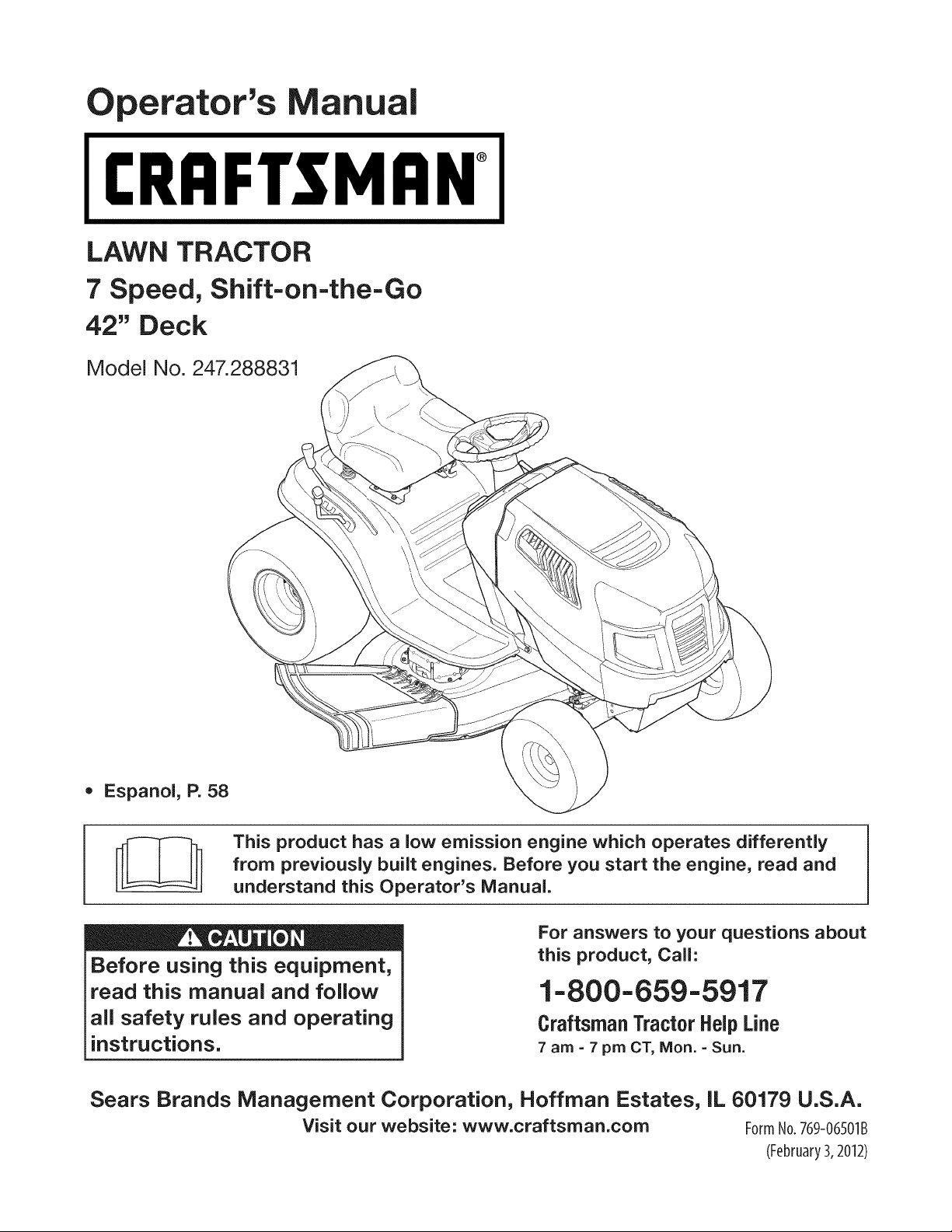
LAWN TRACTOR
7 Speed, Shift-on=the=Go
42" Deck
Model No. 247.288831
•Espanol, P. 58
This product has a low emission engine which operates differently
from previously built engines. Before you start the engine, read and
understand this Operator's Manual.
Before using this equipment,
read this manual and follow
all safety rules and operating
instructions.
For answers to your questions about
this product, Call:
1-800=659=5917
Craftsman Tractor Help Line
7am = 7 pm CT, Mort. =Sun.
Sears Brands Management Corporation, Hoffman Estates, IL 60179 U.S.A.
Visit our website: www.craftsman.com FormNo.769-06501B
(February3,2012)
Warranty Statement .......................................................... 2
Safety Instructions ............................................................ 3
Slope Gauge ..................................................................... 8
Assembly ........................................................................... 9
Operation ........................................................................ 11
Service and Maintenance .............................................. 17
Off-Season Storage ........................................................ 26
Trou bleshooting .............................................................. 27
Labels ............................................................................. 28
Parts List ......................................................................... 30
Espa_ol ............................................................................ 58
Service Numbers ............................................. Back Cover
CRAFTSMAN FULL WARRANTY
FORTWOYEARSfromthe dateof purchase,allnon-expendablepartsof this ridingequipmentarewarrantedagainstany defectsin material
orworkmanship.Adefectivenon-expendablepartwill receivefree in-homerepairor replacementif repairis impossible.
FORFiVEYEARSfromthedate of purchase,the frameof this ridingequipmentiswarrantedagainstany defectsin materialor workmanship.
A defectiveframewill receivefree in-homerepairor replacementif repairis impossible.
FORTENYEARSfromthe dateof purchase,thefrontaxle of this riding equipmentis warrantedagainstany defectsin materialor workman-
ship.A defectivefrontaxle will receivefree in-homerepairor replacementif repairis impossible.
FOR90 DAYSfromthe dateof purchase,the battery(anexpendablepart)of this ridingequipmentis warrantedagainstany defectsin material
orworkmanship(ourtestingprovesthat it will not hold a charge). A defectivebatterywill receivefree in-homereplacement.
ADDITIONALLIFETIMELIMITEDWARRANTYon CASTIRONFRONTAXLE(if equipped)
FORAS LONGAS ITIS USEDbythe originalownerafterthe tenthyearfromthe dateof purchase,thecast ironfrontaxle (ifequipped)of
this ridingequipmentiswarrantedagainstanydefectsinmaterialor workmanship.Withproofof purchase,a defectivecastironfrontaxlewill
receivefreein-homereplacement.
WARRANTYSERVICE
Forwarrantycoveragedetailsto obtainfree repairor replacement,call 1-800-659-5917or visitthe web site:www.craftsman.corn
In allcasesabove,if part repairor replacementis impossible,the ridingequipmentwill be replacedfreeof chargewiththe sameor an
equivalentmodel.
Allof theabovewarrantycoverageisvoidif thisridingequipmentis everusedwhileprovidingcommercialservicesor if rentedto anotherperson.
This warranty covers ONLYdefects in material andworkmanship. Warranty coverage does NOT include:
• Expendableparts(exceptbattery)thatcanwear outfromnormalusewithinthe warrantyperiod,includingbut not limitedto blades,
sparkplugs,aircleaners,belts,and oil filters.
• Standardmaintenanceservicing,oilchanges,or tune-ups.
• Tire replacementor repaircausedby puncturesfrom outsideobjects,such as nails,thorns,stumps,or glass.
• Tireor wheelreplacementor repairresultingfromnormalwear,accident,or improperoperationor maintenance.
• Repairsnecessarybecauseof operatorabuse,includingbutnot limitedto damagecausedbytowingobjectsbeyondthe capabilityof
the ridingequipment,impactingobjectsthatbendtheframe,axle assemblyorcrankshaft,or over-speedingthe engine.
• Repairsnecessarybecauseof operatornegligence,includingbutnot limitedto,electricaland mechanicaldamagecausedby
improperstorage,failureto usethe propergradeandamountof engineoil,failureto keepthe deckclearof flammabledebris,or
failureto maintainthe ridingequipmentaccordingto the instructionscontainedin the operator'smanual.
• Engine(fuel system)cleaningorrepairscausedbyfuel determinedto becontaminatedor oxidized(stale). Ingeneral,fuel shouldbe
usedwithin30 daysof its purchasedate.
• Normaldeteriorationandwearof the exteriorfinishes,or productlabel replacement.
Thiswarrantygivesyou specificlegalrights,andyoumay alsohaveother rightswhichvaryfrom stateto state.
Sears Brands ManagementCorporation, Hoffman Estates, IL 60179
EngineOil: SAE30
Fuel: UnleadedGasoline
SparkPlug: Champion®RC12YC
Engine: Briggs& StrattonI/C®
Model Number:
Serial Number:
Dateof Purchase:
Recordthe modelnumber,serialnumber,
anddateof purchaseabove.
© KCD IR LLC 2
Thissymbolpointsout importantsafetyinstructionswhich,if not
followed,couldendangerthepersonalsafetyand/orpropertyof
yourselfandothers. Readand followall instructionsin thismanual
beforeattemptingto operatethismachine.Failureto complywith
theseinstructionsmayresultin personalinjury.Whenyou seethis
symbol,HEEDITSWARNING!
CALIFORNIA PROPOSITION 65
EngineExhaust,someof its constituents,andcertainvehicle
componentscontainoremit chemicalsknownto Stateof California
to causecancerand birthdefects or other reproductiveharm.
Batteryposts,terminals,and relatedaccessoriescontainleadand
leadcompounds,chemicalsknownto the Stateof Californiato
causecancerand reproductiveharm.Washhandsafterhandling.
Thismachinewasbuiltto beoperatedaccordingto the safeopera-
tion practicesinthis manual.As with anytype of powerequipment,
carelessnessorerroron the partof the operatorcan resultin serious
injury.Thismachineis capableof amputatingfingers,hands,toes
andfeet and throwingdebris.Failureto observethe followingsafety
instructionscouldresultin seriousinjuryor death.
Your Responsibility--Restrict the useof thispowermachineto
personswho read,understandandfollow thewarningsand instruc-
tionsin this manualand on the machine.
SAVE THESE INSTRUCTIONS!
GENERAL OPERATION
•Read,understand,andfollowall instructionson the machineand
in themanual(s)beforeattemptingto assembleandoperate.
Keepthis manualina safe placefor futureand regularreference
andfor orderingreplacementparts.
• Befamiliarwithall controlsandtheir properoperation.Knowhow
to stopthe machineanddisengagethemquickly.
• Neverallowchildrenunder14yearsoldto operatethis machine.
Children14yearsoldand over shouldreadand understandthe
operationinstructionsandsafetyrulesinthismanualandshould
betrainedandsupervisedbya parent.
• Neverallowadultsto operatethis machinewithoutproper
instruction.
• Tohelpavoidbladecontactor a thrownobjectinjury,keep
bystanders,helpers,childrenandpetsat least75feet fromthe
machinewhile it is in operation.Stopmachineif anyoneenters
the area.
• Thoroughlyinspectthe areawherethe equipmentis to be used.
Removeallstones,sticks,wire,bones,toys,and otherforeign
objectswhichcouldbe pickedupand thrownby the blade(s).
Thrownobjectscan causeseriouspersonalinjury.
• Planyour mowingpatternto avoiddischargeof materialtoward
roads,sidewalks,bystandersandthe like.Also,avoiddischarg-
ingmaterialagainstawall or obstructionwhich maycause
dischargedmaterialto ricochetbacktowardthe operator.
• Alwayswear safetyglassesor safetygogglesduringoperation
andwhile performingan adjustmentor repairto protectyoureyes.
Thrownobjectswhichricochetcancauseseriousinjuryto the
eyes.
• Wearsturdy,rough-soledworkshoesandclose-fittingslacksand
shirts.Loosefittingclothesandjewelrycanbe caughtin movable
parts.Neveroperatethismachineinbare feet or sandals.
• Beawareof the mowerandattachmentdischargedirectionand
do not pointit at anyone.Donot operatethe mowerwithoutthe
dischargecoveror entiregrass catcherin its properplace.
Donot put handsor feetnearrotatingpartsor underthe cutting
deck. Contactwiththe blade(s)can amputatehandsandfeet.
A missingor damageddischargecovercan causebladecontact
or thrownobjectinjuries.
• Stoptheblade(s)whencrossinggraveldrives,walks,or roads
andwhile notcuttinggrass.
• Watchfor trafficwhenoperatingnearorcrossingroadways.This
machineis not intendedfor useonany public roadway.
• Donot operatethe machinewhile underthe influenceof alcohol
or drugs.
• Mowonly indaylightorgoodartificiallight.
Nevercarrypassengers.
• Disengageblade(s)beforeshiftinginto reverse.Backup slowly.
Alwayslookdownandbehindbeforeandwhile backingto avoida
back-overaccident.
3
• Slowdownbeforeturning.Operatethe machinesmoothly.Avoid
erraticoperationandexcessivespeed.
Disengageblade(s),setparkingbrake,stopengine and wait until
the blade(s)cometo a completestopbeforeremovinggrass
catcher,emptyinggrass,uncloggingchute,removinganygrassor
debris,or makinganyadjustments.
Neverleavea runningmachineunattended.Alwaysturnoff
blade(s),setparkingbrake,stopengineand removekey before
dismounting.
Useextracare whenloadingorunloadingthe machineintoa
trailerortruck.Thismachineshouldnot bedrivenupor down
ramp(s),becausethe machinecouldtip over,causingserious
personalinjury.The machinemustbe pushedmanuallyon
ramp(s)to loador unloadproperly.
Mufflerandenginebecomehotand can causea burn.Do not
touch.
Checkoverheadclearancescarefullybeforedrivingunderlow
hangingtree branches,wires,dooropeningsetc., wherethe
operatormaybe struckor pulledfromthe machine,whichcould
resultinseriousinjury.
Disengageallattachmentclutchesand depressthe brakepedal
completelybeforeattemptingto start engine.
Yourmachineisdesignedto cutnormalresidentialgrassof a
heightnomorethan 10".Do not attemptto mowthroughunusually
tall,dry grass(e.g.,pasture)or piles of dry leaves.Dry grass or
leavesmaycontactthe engineexhaustand/or buildup on the
mowerdeckpresentinga potentialfire hazard.
Useonlyaccessoriesandattachmentsapprovedfor this machine
by the machinemanufacturer.Read,understandandfollowall
instructionsprovidedwiththe approvedaccessoryor attachment.
Fora list of approvedaccessoriesandattachments,call 1-800-
659-5917.
Dataindicatesthatoperators,age60 years and above,are
involvedin a largepercentageof riding mower-relatedinjuries.
Theseoperatorsshouldevaluatetheirabilityto operatethe riding
mowersafelyenoughto protectthemselvesandothersfrom
seriousinjury.
If situationsoccurwhichare not coveredin this manual,usecare
andgoodjudgment.Contact1-800-659-5917for informationand
assistance.
SLOPE OPERATION
Slopesarea majorfactorrelatedto lossof controlandtip-over
accidentswhichcan resultin severeinjuryor death.All slopes require
extracaution.Ifyoucannotback up the slopeor if youfeel uneasyon
it, do not mowit.
Foryoursafety,use the SlopeGuideincludedas partof this manual
to measureslopesbeforeoperatingthis machineona slopedor hilly
area. Ifthe slopeis greaterthan15degreesas shownonthe Slope
Guide,do notoperatethis machineonthatarea or seriousinjurycould
result.
Do:
oMowupand down slopes,not across.Exerciseextremecaution
whenchangingdirectionon slopes.
• Watchfor holes,ruts,bumps,rocks,or other hiddenobjects.
Uneventerraincouldoverturnthe machine.Tallgrasscan hide
obstacles.
Useslowspeed.Choosea lowenoughspeedsettingso that
you will nothaveto stopor shiftwhileon the slope.Tiresmay
lose tractionon slopeseventhoughthe brakesarefunctioning
properly.Alwayskeepmachinein gearwhen goingdownslopes
to takeadvantageof enginebrakingaction.
• Followthe manufacturer'srecommendationsfor wheelweights
or counterweightsto improvestability.Forrecommendations,call
1-800-659-5917.
• Useextracarewithgrasscatchersor otherattachments.These
can changethe stabilityof the machine.
Keepallmovementon the slopes slowand gradual.Do not make
suddenchangesinspeedor direction.Rapidengagementor
brakingcouldcausethe frontof the machineto lift andrapidlyflip
overbackwardswhichcouldcauseseriousinjury.
• Avoidstartingorstoppingona slope.Iftireslosetraction,disen-
gagethe blade(s)andproceedslowlystraightdownthe slope.
DoNot:
• Donot turnon slopesunlessnecessary;then,turnslowlyand
graduallydownhill,if possible.
• Donot mowneardrop-offs,ditchesor embankments.The mower
could suddenlyturnover if a wheelis overthe edgeof a cliff,
ditch,or if an edgecavesin.
• Donot try to stabilizethe machineby puttingyourfooton the
ground.
• Donot usea grasscatcheron steepslopes.
• Donot mowon wetgrass.Reducedtractioncouldcausesliding.
• Donot attemptto coastdownhill.Over-speedingmaycausethe
operatorto lose controlof the machineresultingin seriousinjury
or death.
• Donot towheavypull behindattachments(e.g.loadeddumpcart,
lawn roller,etc.)on slopesgreaterthan5 degrees.Whengoing
down hill,the extraweighttendsto pushthe tractorandmay
causeyou to loosecontrol(e.g.tractormayspeedup, brakingand
steeringabilityare reduced,attachmentmayjack-knifeand cause
tractorto overturn).
4
CHILDREN
Tragicaccidentscanoccurifthe operatoris notalert to the presence
of children.Childrenareoftenattractedto the machineandthe mowing
activity.Theydo notunderstandthe dangers.Neverassumethat
childrenwill remainwhereyou lastsawthem.
• Keepchildrenout of the mowingareaand inwatchfulcare of a
responsibleadultotherthanthe operator.
• Bealert andturnmachineoff ifa childentersthe area.
• Beforeandwhilebacking,lookbehindanddownfor small
children.
Nevercarrychildren,evenwiththe blade(s)shutoff.Theymay
fall offand be seriouslyinjuredorinterferewithsafemachine
operation.
• Useextremecarewhenapproachingblindcorners,doorways,
shrubs,treesor otherobjectsthatmay block yourvisionof a child
whomayrunintothe machine.
Toavoidback-overaccidents,alwaysdisengagethe cutting
blade(s)beforeshiftingintoReverse.Ifequipped,the "Reverse
CautionMode"(bladesoperatewhilemachineridesinreverse)
shouldnotbe usedwhenchildrenor othersarearound.
Keepchildrenawayfrom hotor runningengines.They cansuffer
burnsfroma hotmuffler.
• Removekeywhenmachineisunattendedto preventunauthorized
operation.
Neverallowchildrenunder14yearsof age to operatethis machine.
Children14andovershouldreadandunderstandthe instructionsand
safeoperationpracticesinthis manualand on the machineand should
betrainedandsupervisedbyan adult.
TOWING
Towonlywitha machinethathasa hitchdesignedfor towing.Do
not attachtowedequipmentexceptat the hitchpoint.
Followthe manufacturersrecommendationforweightlimitsfor
towedequipmentandtowingon slopes.For recommendations,
call 1-800-659-5917.
Neverallowchildrenor othersinoron towedequipment.
Onslopes,theweightof thetowedequipmentmaycauselossof
tractionandloss of control.
Alwaysuseextracautionwhentowingwitha machinecapableof
makingtightturns (e.g."zero-turn"ride-onmower). Makewide
turnsto avoidjack-knifing.
Travelslowlyandallowextradistanceto stop.
Do notcoastdownhill.
SERVICE
SafeHandlingof Gasoline
Toavoidpersonalinjuryorpropertydamageuse extremecarein
handlinggasoline.Gasolineisextremelyflammableandthe vaporsare
explosive.Seriouspersonalinjurycanoccurwhengasolineis spilled
on yourselforyour clotheswhichcan ignite.Washyourskinand
changeclothesimmediately.
• Useonly anapprovedgasolinecontainer.
Neverfill containersinsidea vehicleoron a truckor trailer bed
witha plasticliner.Alwaysplacecontainerson the groundaway
fromyourvehiclebeforefilling.
Whenpractical,removegas-poweredequipmentfrom the truck
or trailerandrefueliton theground.Ifthis isnot possible,then
refuelsuchequipmenton a trailerwith a portablecontainer,rather
than froma gasolinedispensernozzle.
Keepthe nozzleincontactwiththe rim of the fueltank or
containeropeningat all timesuntilfuelingiscomplete.Donot use
a nozzlelock-opendevice.
Extinguishall cigarettes,cigars,pipesandothersourcesof
ignition.
• Neverfuel machineindoors.
Neverremovegascap or addfuelwhilethe engineis hotor run-
ning.Allowengineto coolat least two minutesbeforerefueling.
Neveroverfill fuel tank. Filltankto no morethan 1/2inchbelow
bottomof filler neckto allowspaceforfuel expansion.
• Replacegasolinecap andtightensecurely.
• Ifgasolineis spilled,wipeitoff the engineandequipment.Move
machineto anotherarea.Wait5 minutesbeforestartingthe
engine.
• To reducefire hazards,keepmachinefree of grass,leaves,or
otherdebrisbuild-up.Cleanup oilor fuel spillageandremoveany
fuel soakeddebris.
• Neverstorethe machineor fuelcontainerinsidewherethere isan
openflame,sparkor pilotlight as ona waterheater,spaceheater,
furnace,clothesdryeror othergasappliances.
Allowa machineto coolat least five minutesbeforestoring.
GeneralService
• Neverrunanengineindoorsorinapoorlyventilatedarea.Engine
exhaustcontainscarbonmonoxide,anodorless,anddeadlygas.
• Beforecleaning,repairing,orinspecting,makecertainthe
blade(s)andallmovingpartshavestopped.Disconnectthespark
plugwireandgroundagainsttheenginetopreventunintended
starting.
• Periodicallychecktomakesurethebladescometocomplete
stopwithinapproximately(5)fivesecondsafteroperatingthe
bladedisengagementcontrol.Ifthebladesdonotstopwithinthe
thistimeframe,yourmachineshouldbeservicedprofessionally
byaSearsorotherqualifiedservicedealer.
• Checkbrakeoperationfrequentlyasitissubjectedtowearduring
normaloperation.Adjustandserviceasrequired.
• Checktheblade(s)andenginemountingboltsatfrequent
intervalsforpropertightness.Also,visuallyinspectblade(s)
fordamage(e.g.,excessivewear,bent,cracked).Replacethe
blade(s)withtheoriginalequipmentmanufacturer's(O.E.M.)
blade(s)only,listedinthismanual.Useofpartswhichdonot
meettheoriginalequipmentspecificationsmayleadtoimproper
performanceandcompromisesafety!
• Mowerbladesaresharp.Wrapthebladeorweargloves,anduse
extracautionwhenservicingthem.
• Keepallnuts,bolts,andscrewstighttobesuretheequipmentis
insafeworkingcondition.
• Nevertamperwiththe safetyinterlocksystemor othersafety
devices.Checktheir properoperationregularly.
• Afterstrikinga foreignobject,stopthe engine,disconnectthe
sparkplugwire(s)and groundagainstthe engine.Thoroughly
inspectthe machinefor anydamage.Repairthe damagebefore
startingandoperating.
• Neverattemptto makeadjustmentsor repairsto the machine
whilethe engineis running.
• Grasscatchercomponentsandthe dischargecoverare subject
to wearanddamagewhichcouldexposemovingpartsor allow
objectsto bethrown.Forsafetyprotection,frequentlycheck
componentsand replaceimmediatelywith originalequipment
manufacturer's(O.E.M.)partsonly,listedinthis manual.Useof
partswhichdo not meetthe originalequipmentspecificationsmay
leadto improperperformanceandcompromisesafety!
• Donot changethe enginegovernorsettingsorover-speedthe
engine.The governorcontrolsthe maximumsafeoperatingspeed
of the engine.
Maintainor replacesafetyand instructionlabels,as necessary.
• Observeproperdisposallawsandregulationsfor gas,oil, etc.to
protecttheenvironment.
• Accordingto the ConsumerProductsSafetyCommission(CPSC)
andthe U.S.EnvironmentalProtectionAgency(EPA),this product
has anAverageUsefulLifeof seven(7)years,or 270hours
of operation.At the endof the AverageUsefulLife,buy a new
machineor havethe machineinspectedannuallybya Searsor
otherqualifiedservicedealerto ensurethat all mechanicaland
safetysystemsare workingproperlyand not wornexcessively.
Failureto doso can resultinaccidents,injuriesor death.
DO NOT MODIFY ENGINE
Toavoid seriousinjuryor death,do notmodifyengineinanyway.
Tamperingwiththe governorsettingcanlead to a runawayengineand
causeit to operateat unsafespeeds.Nevertamperwithfactorysetting
of enginegovernor.
NOTICE REGARDING EMISSIONS
Engineswhicharecertifiedto complywithCaliforniaandfederal
EPAemissionregulationsfor SORE(SmallOffRoadEquipment)are
certifiedto operateon regularunleadedgasoline,and may include
the followingemissioncontrolsystems:EngineModification(EM)and
ThreeWayCatalyst(TWO)if so equipped.
SPARK ARRESTOR
Thismachineis equippedwith an internalcombustionengineand
shouldnotbe usedonor nearanyunimprovedforest-covered,
brushcoveredorgrass-coveredlandunlessthe engine'sexhaust
systemisequippedwitha sparkarrestormeetingapplicablelocalor
statelaws(if any).
Ifa sparkarrestoris used,it shouldbe maintainedin effectiveworking
orderby the operator.Inthe Stateof Californiatheaboveis required
by law (Section4442of the CaliforniaPublicResourcesCode).Other
statesmayhavesimilarlaws.Federallawsapplyonfederallands.
A sparkarrestorfor the muffleris availablethroughyournearestSears
PartsandRepairServiceCenter.
6
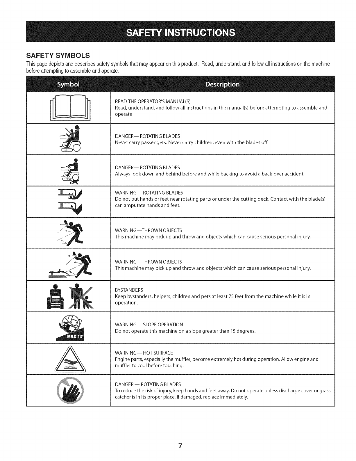
SAFETY SYMBOLS
Thispagedepictsanddescribessafety symbolsthat may appearon this product. Read,understand,and follow all instructionson the machine
beforeattemptingto assembleandoperate.
0
A
READ THE OPERATOR'S MANUAL(S)
Read, understand, and follow all instructions in the manual(s) before attempting to assemble and
operate
DANGER-- ROTATING BLADES
Never carry passengers. Never carry children, even with the blades off.
DANGER-- ROTATING BLADES
Always look down and behind before and while backing to avoid a back-over accident.
WARNING-- ROTATING BLADES
Do not put hands or feet near rotating parts or under the cutting deck. Contact with the blade(s)
can amputate hands and feet.
WARNING--THROWN OBJECTS
This machine may pick up and throw and objects which can cause serious personal injury.
WARNING--THROWN OBJECTS
This machine may pick up and throw and objects which can cause serious personal injury.
BYSTANDERS
Keep bystanders, helpers, children and pets at least 75 feet from the machine while it is in
operation.
WARNING-- SLOPE OPERATION
Do not operate this machine on a slope greater than 15 degrees.
WARNING-- HOT SURFACE
Engine parts, especially the muffler, become extremely hot during operation. Allow engine and
muffler to cool before touching.
DANGER-- ROTATING BLADES
To reduce the risk of injury, keep hands and feet away. Do not operate unless discharge cover or grass
catcher is in its proper place. If damaged, replace immediately.
7
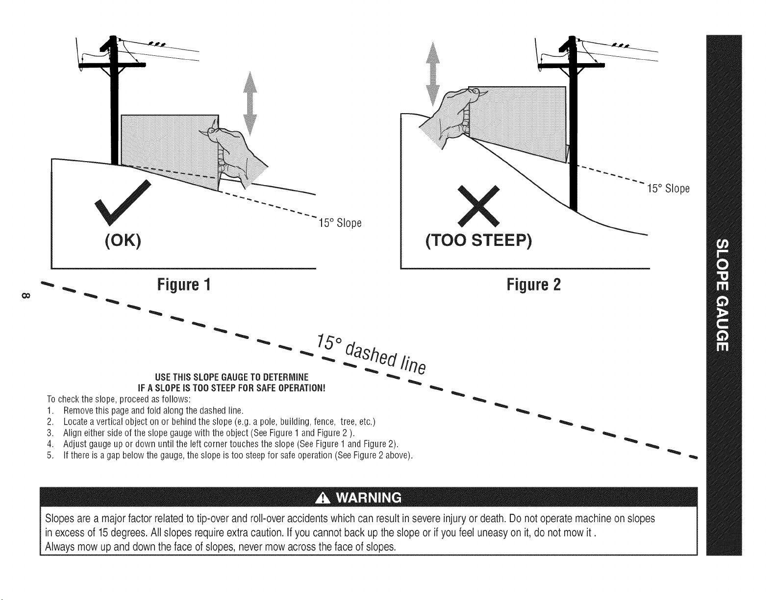
(OK)
15° Slope X
(TOO STEEP)
15° Slope
'_. _ Figure1
USETHISSLOPEGAUGETODETERMINE
IFA SLOPEIS TOOSTEEPFORSAFEOPERATION!
To checkthe slope,proceedas follows:
1. Removethis pageand fold along the dashedline.
2. Locatea verticalobject on or behindthe slope (e.g. a pole, building,fence, tree, etc.)
3. Align eitherside of the slope gaugewith the object (See Figure1 and Figure2 ).
4. Adjust gaugeup or down until the left cornertouchesthe slope (SeeFigure1and Figure2).
5.
15°
dashed line
If there is agap belowthe gauge,the slope is too steepfor safeoperation(SeeFigure2 above).
Figure2
Slopes are a majorfactor related to tip-over and roll-over accidents which can result in severe injury or death. Do not operate machine on slopes
in excess of 15 degrees. All slopes require extra caution. If you cannot back up the slope or if you feel uneasy on it, do not mow it.
Always mow up and down the face of slopes, never mow across the face of slopes.
IMPORTANT:Yourtractoris shippedwithmotoroil in theengine.
However,you MUSTcheckthe oil levelbeforeoperating.Referto the
Service& Maintenancesectionfor instructionson checkingtheoil
level.
Attaching the Battery Cables
CALIFORNIA PROPOSITION 65
Batteryposts,terminals,andrelatedaccessoriescontainleadand
leadcompounds,chemicalsknownto the Stateof Californiato
causecancerand reproductiveharm.Washhandsafter handling.
Whenattachingbatterycables,alwaysconnectthe POSITIVE(Red)
wireto its terminalfirst,followedby the NEGATIVE(Black)wire.
Forshippingreasons,bothbatterycablesonyourequipmentmay
havebeenleftdisconnectedfrom the terminalsat the factory.To
connectthe batterycables,proceedasfollows:
NOTE:Thepositivebatteryterminalis markedPos.(+).The negative
batteryterminalis markedNeg.(-).
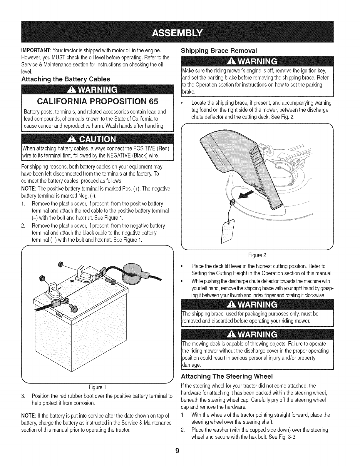
1. Removethe plasticcover,if present,fromthe positivebattery
terminaland attachthe redcableto the positivebatteryterminal
(+)withthe bolt andhexnut.See Figure1.
2. Removethe plasticcover,if present,fromthe negativebattery
terminaland attachthe black cableto the negativebattery
terminal(-) withthe bolt andhex nut. See Figure1.
f
J
Figure1
3. Positionthe redrubber boot over the positivebatteryterminal to
helpprotectit fromcorrosion.
NOTE:If thebatteryis put into serviceafterthe dateshownon topof
battery,chargethe batteryas instructedinthe Service& Maintenance
sectionof this manualpriorto operatingthe tractor.
Shipping Brace Removal
Makesurethe ridingmower'sengineis off, removetheignitionkey,
andset the parkingbrakebeforeremovingthe shippingbrace.Refer
Itothe Operationsectionfor instructionson howto setthe parking
lbrake.
• Locatethe shippingbrace,if present,andaccompanyingwarning
tag foundonthe rightsideof the mower,betweenthe discharge
chutedeflectorand the cuttingdeck. See Fig. 2.
//
Figure2
Placethe decklift leverinthe highestcuttingposition.Referto
SettingtheCuttingHeightin the Operationsectionof thismanual.
Whilepushingthedischargechuteddlectortowardsthemachinewith
yourlefthand,removetheshippingbracewithyourrighthandbygrasp-
ingitbetweenyourthumbandindexfingerandrotatingitclockwise.
The shippingbrace,usedfor packagingpurposesonly, mustbe
removedand discardedbeforeoperatingyour ridingmower.
The mowingdeck iscapableof throwingobjects.Failureto operate
the ridingmowerwithoutthe dischargecoverin the properoperating
Ipositioncould resultin seriouspersonalinjuryand/orproperty
ldamage.
Attaching The Steering Wheel
Ifthe steeringwheelfor yourtractordid notcomeattached,the
hardwarefor attachingit has beenpackedwithinthe steeringwheel,
beneaththe steeringwheelcap.Carefullypry off the steeringwheel
cap andremovethe hardware.
1. With the wheelsof the tractorpointingstraightforward,placethe
steeringwheeloverthe steeringshaft.
2. Placethe washer(withthe cuppedsidedown)overthe steering
wheeland securewiththe hex bolt.See Fig.3-3.
9
f
\
Figure3
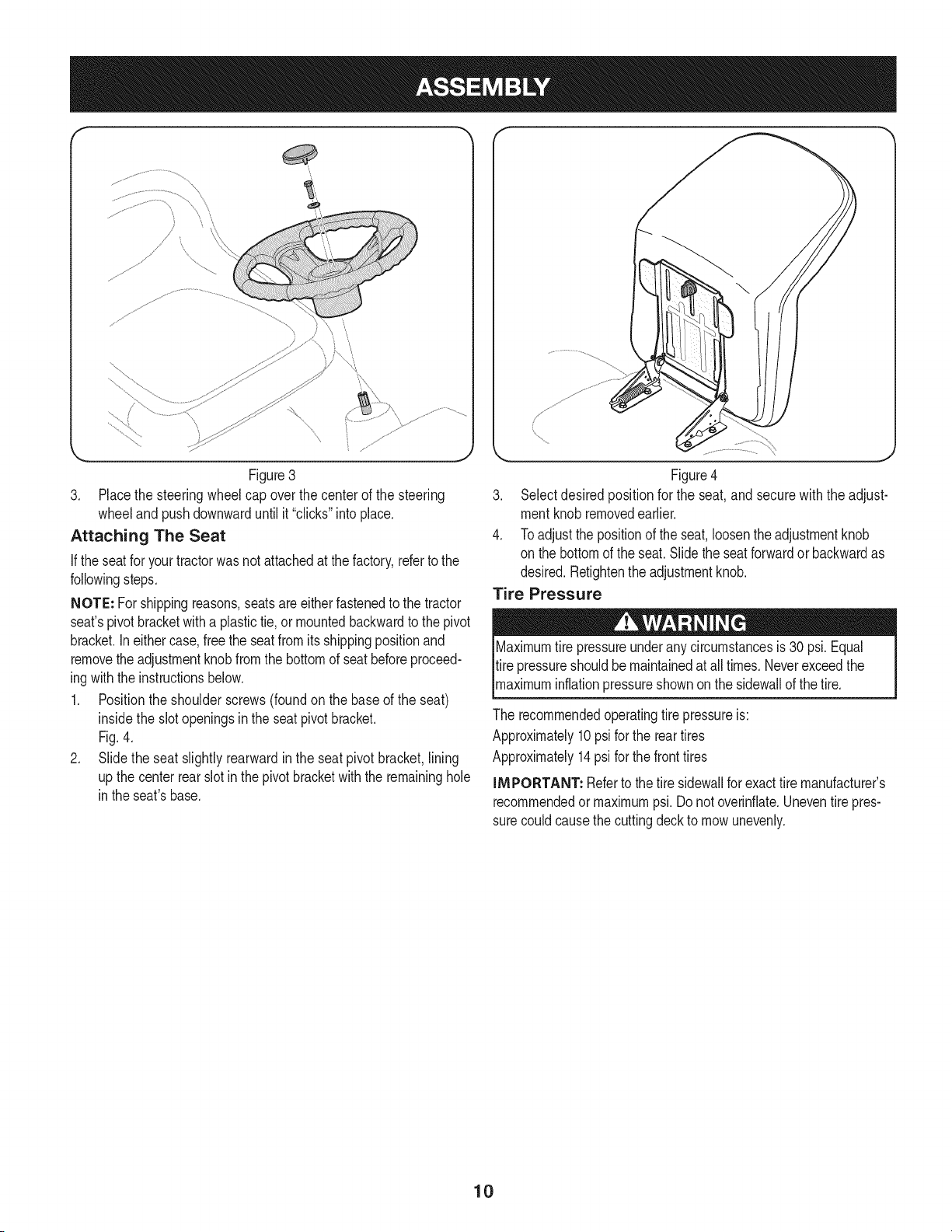
3. Placethe steeringwheelcap overthe center of the steering
wheeland pushdownwarduntilit "clicks"intoplace.
Attaching The Seat
If the seatfor yourtractorwasnotattachedat thefactory,refertothe
followingsteps.
NOTE: Forshippingreasons,seatsareeitherfastenedto the tractor
seat'spivotbracketwitha plastictie,or mountedbackwardto the pivot
bracket.Ineithercase,free the seatfromits shippingpositionand
removethe adjustmentknobfromthe bottomof seatbeforeproceed-
ingwiththe instructionsbelow.
1. Positionthe shoulderscrews(foundon the baseof the seat)
insidethe slot openingsinthe seatpivotbracket.
Fig.4.
2. Slide the seat slightlyrearwardin the seat pivot bracket,lining
up the centerrearslot in thepivot bracketwith the remaininghole
in theseat'sbase.
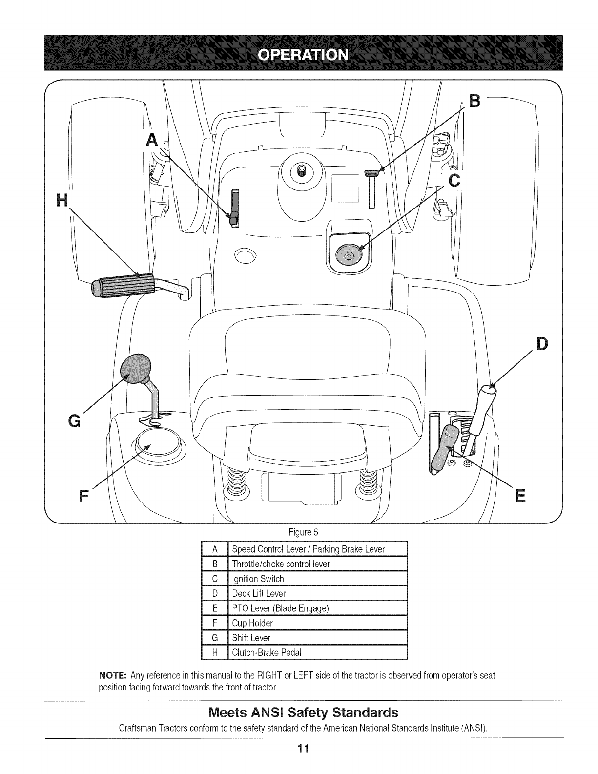
Figure4
3. Selectdesired positionfor the seat,and secure with the adjust-
mentknobremovedearlier.
4. Toadjust the positionof the seat,loosenthe adjustmentknob
on the bottomof the seat.Slidethe seatforwardor backwardas
desired.Retightenthe adjustmentknob.
Tire Pressure
X
Maximumtire pressureunderany circumstancesis 30 psi.Equal
tire pressureshouldbe maintainedat all times. Neverexceedthe
_maxmum nfat onpressureshownon the s dewa of thet re.
The recommendedoperatingtire pressureis:
Approximately10psi forthe reartires
Approximately14psi forthe fronttires
IMPORTANT: Referto the tire sidewallfor exacttire manufacturer's
recommendedormaximumpsi.Donot overinfiate.Uneventirepres-
surecouldcausethe cuttingdeckto mowunevenly.
10
A
C
G
D
F
Figure5
A SpeedControlLever/ParkingBrakeLever
B Throttle/chokecontrollever
C IgnitionSwitch
D DeckLiftLever
E PTOLever(BladeEngage)
F Cup Holder
G Shift Lever
H Clutch-BrakePedal
NOTE: Any referenceinthis manualto the RIGHTor LEFT sideof the tractoris observedfromoperator'sseat
positionfacingforwardtowardsthe frontof tractor.
Meets ANS! Safety Standards
CraftsmanTractorsconformto the safetystandardof theAmericanNationalStandardsInstitute(ANSI).
11
E
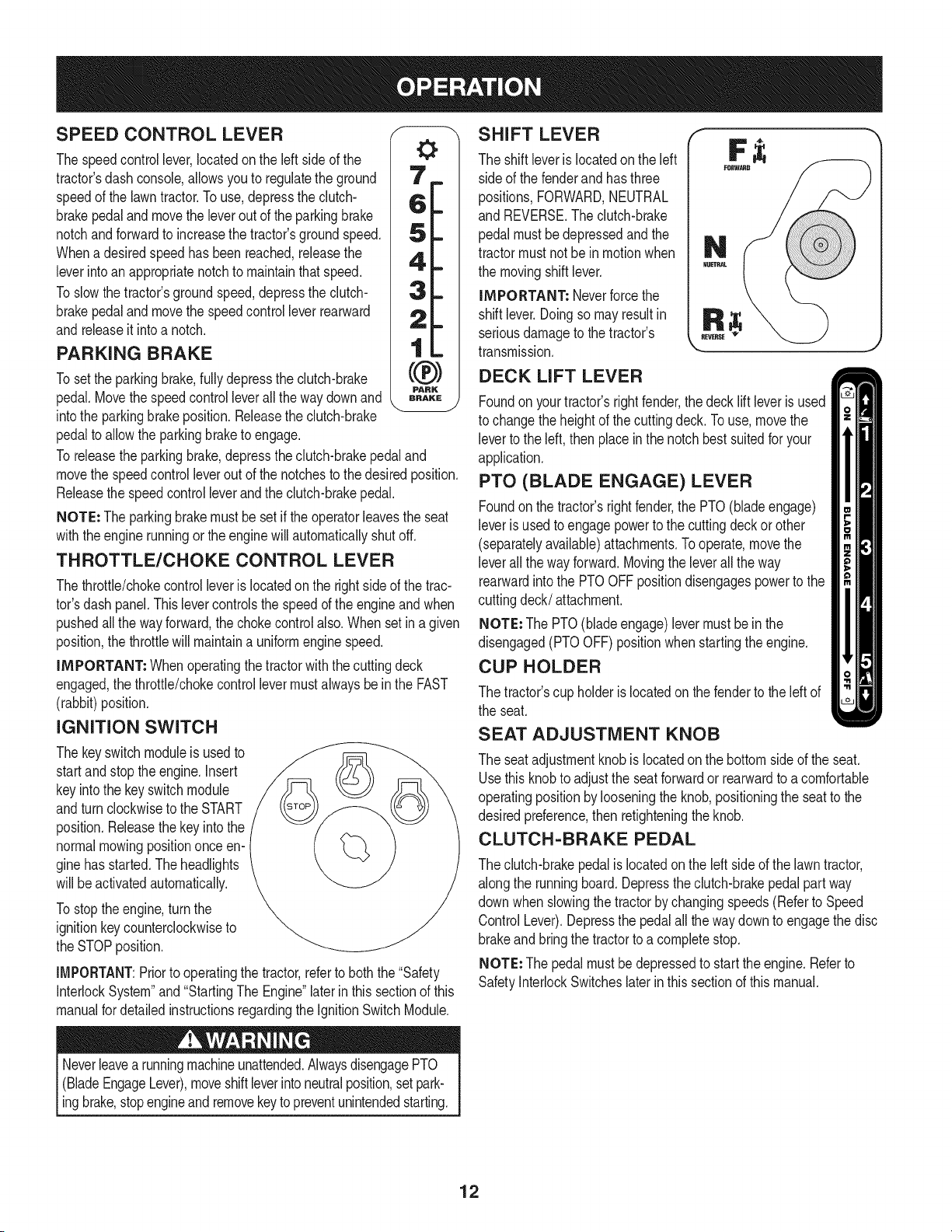
SPEED CONTROL LEVER
The speedcontrollever,locatedonthe left sideof the
tractor'sdash console,allows youto regulatethe ground
speedof the lawntractor.To use,depressthe clutch-
brakepedalandmovethe leverout of the parkingbrake
notchandforwardto increasethe tractor'sgroundspeed.
Whenadesiredspeedhas beenreached,releasethe
leverintoan appropriatenotchto maintainthatspeed.
Toslowthetractor'sgroundspeed,depressthe clutch-
brakepedalandmovethe speedcontrolleverrearward
andreleaseit intoa notch.
PARKING BRAKE
Tosetthe parkingbrake,fullydepressthe clutch-brake
pedal.Movethe speedcontrolleverall the waydownand
intothe parkingbrakeposition.Releasethe clutch-brake
pedalto allowthe parkingbraketo engage.
To releasethe parkingbrake,depressthe clutch-brakepedaland
movethe speedcontrolleveroutof thenotchesto thedesiredposition.
Releasethe speedcontrolleverandthe clutch-brakepedal.
NOTE: The parkingbrakemustbe set if the operatorleavesthe seat
withtheenginerunningor the enginewill automaticallyshutoff.
THROTTLE/CHOKE CONTROL LEVER
Thethrottle/chokecontrolleveris locatedon the rightsideof the trac-
tor'sdash panel.Thislevercontrolsthespeedof the engineandwhen
pushedall the wayforward,the chokecontrol also.Whenset in a given
position,the throttlewill maintaina uniformenginespeed.
IMPORTANT: Whenoperatingthetractorwiththe cuttingdeck
engaged,the throttle/chokecontrollevermustalwaysbeinthe FAST
(rabbit)position.
IGNITION SWITCH
The keyswitchmoduleis usedto
startand stopthe engine.Insert
keyintothe keyswitchmodule
andturnclockwiseto the START
position.Releasethekeyinto the
normalmowingpositiononceen-
ginehas started.The headlights
will beactivatedautomatically.
Tostoptheengine,turnthe
ignitionkeycounterclockwiseto
the STOPposition.
IMPORTANT:Priorto operatingthe tractor,referto boththe "Safety
InterlockSystem"and"StartingThe Engine"laterin this sectionof this
manualfor detailedinstructionsregardingthe IgnitionSwitchModule.
Neverleavea runningmachineunattended.AlwaysdisengagePTO
(BladeEngageLever),moveshiftleverinto neutralposition,setpark-
ingbrake,stopengineand removekey topreventunintendedstarting.
SHIFT LEVER
The shift leveris locatedon the left
side of the fenderand hasthree
positions,FORWARD,NEUTRAL
and REVERSE.The clutch-brake
pedalmustbedepressedand the
tractormustnot bein motionwhen
the movingshift lever.
IMPORTANT: Neverforcethe
shift lever.Doingso mayresultin
seriousdamageto thetractor's
transmission.
DECK LIFT LEVER
Foundonyourtractor'srightfender,the decklift leveris used
to changethe heightof thecuttingdeck.To use, movethe
leverto the left, thenplace inthe notchbestsuitedfor your
application.
PTO (BLADE ENGAGE) LEVER
Foundonthe tractor'srightfender,the PTO(blade engage)
leveris usedto engagepowerto the cuttingdeck or other
(separatelyavailable)attachments.Tooperate,movethe
leverall thewayforward.Movingthe leverallthe way
rearwardinto the PTOOFFpositiondisengagespowerto the
cuttingdeck/attachment.
NOTE: The PTO(bladeengage)levermustbe in the
disengaged(PTOOFF)positionwhenstartingtheengine.
CUP HOLDER
The tractor'scup holderis locatedon the fenderto the left of
the seat.
SEAT ADJUSTMENT KNOB
The seatadjustmentknob is locatedon the bottomsideof the seat.
Usethis knobto adjustthe seatforwardor rearwardto a comfortable
operatingpositionby looseningthe knob,positioningthe seatto the
desiredpreference,then retighteningthe knob.
CLUTCH-BRAKE PEDAL
The clutch-brakepedalis locatedonthe left sideof the lawntractor,
alongthe runningboard.Depressthe clutch-brakepedalpart way
downwhen slowingthe tractorbychangingspeeds(Referto Speed
ControlLever).Depressthe pedalall the waydownto engagethe disc
brakeandbringthe tractorto a completestop.
NOTE: Thepedal mustbe depressedto startthe engine.Referto
SafetyInterlockSwitcheslaterin thissectionof thismanual.
12
Gas and Oil Fill=up
0il
iMPORTANT: Yourtractorisshippedwith motoroilinthe engine.
However,you MUSTcheckthe oil levelbeforeoperating.Be careful
not tooverfill.
For instructionson howto checkthe engineoil, referto CheckingThe
EngineOilin the Serviceand Maintenancesectionof this manual.
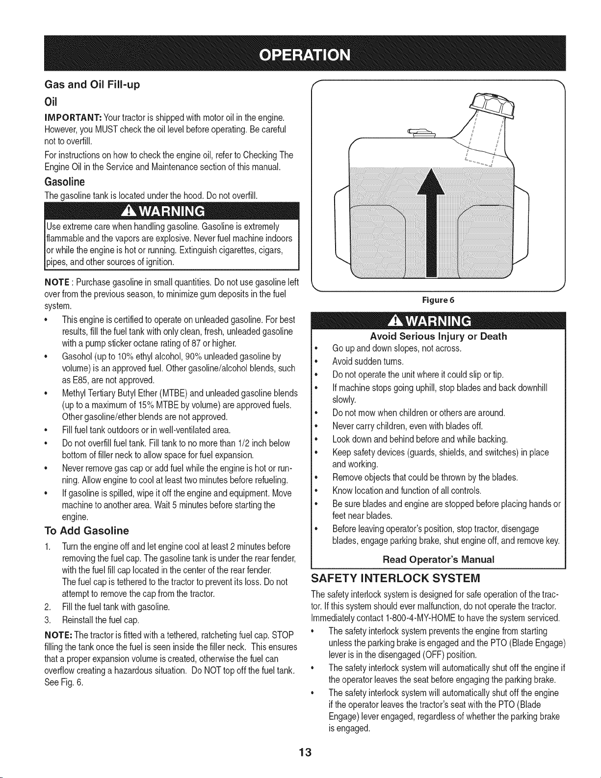
Gasoline
Thegasolinetank islocatedunderthe hood.Do notoverfill.
Useextremecarewhenhandlinggasoline.Gasolineis extremely
flammableandthe vaporsareexplosive.Neverfuel machineindoors
orwhile theengineishotor running.Extinguishcigarettes,cigars,
p pes,andothersourcesof gn t on.
NOTE : Purchasegasolineinsmallquantities.Do notuse gasolineleft
overfromthe previousseason,to minimizegumdepositsinthe fuel
system.
•Thisengineiscertifiedto operateonunleadedgasoline.For best
results,fill thefuel tankwithonlyclean,fresh,unleadedgasoline
witha pumpstickeroctaneratingof 87or higher.
•Gasohol(upto 10%ethylalcohol,90% unleadedgasolineby
volume)is anapprovedfuel. Othergasoline/alcoholblends,such
as E85,arenot approved.
•MethylTertiaryButylEther(MTBE)andunleadedgasolineblends
(upto a maximumof 15%MTBEby volume)areapprovedfuels.
Othergasoline/etherblendsarenotapproved.
•Fill fueltankoutdoorsorin well-ventilatedarea.
•Do notoverfillfuel tank. Filltankto no morethan 1/2inchbelow
bottomof fillerneck to allowspacefor fuel expansion.
•Neverremovegas cap oradd fuel whilethe engineishot or run-
ning.Allowengineto cool at leasttwo minutesbeforerefueling.
•If gasolineisspilled,wipe itoffthe engineandequipment.Move
machineto anotherarea.Wait5 minutesbeforestartingthe
engine.
To Add Gasoline
1. Turnthe engineoff and let enginecoolat least2 minutesbefore
removingthe fuelcap.Thegasolinetankisunderthe rearfender,
withthe fuelfill cap locatedinthecenterof the rearfender.
Thefuel cap is tetheredto the tractorto preventitsloss. Donot
attemptto removethe cap fromthetractor.
2. Fill thefuel tank with gasoline.
3. Reinstallthe fuelcap.
NOTE: The tractoris fittedwith a tethered,ratchetingfuel cap. STOP
fillingthe tankonce the fuelis seeninsidethefiller neck. Thisensures
thata properexpansionvolumeis created,otherwisethe fuel can
overflowcreatinga hazardoussituation. Do NOTtop off the fuel tank.
SeeFig. 6.
Figure 6
Avoid Serious injury or Death
•Go upand downslopes,notacross.
•Avoidsuddenturns.
•Donot operatethe unitwhereitcould slipor tip.
• Ifmachinestopsgoinguphill,stopbladesandbackdownhill
slowly.
•Donot mowwhenchildrenorothersarearound.
•Nevercarrychildren,evenwithbladesoff.
•Lookdownandbehindbeforeand whilebacking.
•Keepsafetydevices(guards,shields,and switches)in place
andworking.
•Removeobjectsthatcould bethrownby the blades.
•Knowlocationandfunctionof allcontrols.
•Besurebladesandenginearestoppedbeforeplacinghandsor
feetnear blades.
•Beforeleavingoperator'sposition,stoptractor,disengage
blades,engageparkingbrake,shutengineoff, and removekey.
Read Operator's Manual
SAFETY INTERLOCK SYSTEM
The safetyinterlocksystemisdesignedfor safeoperationof the trac-
tor.If this systemshouldevermalfunction,do notoperatethe tractor.
Immediatelycontact1-800-4-MY-HOMEto havethe systemserviced.
• The safetyinterlocksystempreventsthe enginefrom starting
unlessthe parkingbrakeis engagedandthe PTO(BladeEngage)
leveris in the disengaged(OFF) position.
• The safetyinterlocksystemwill automaticallyshutoff the engineif
the operatorleavesthe seatbeforeengagingthe parkingbrake.
• The safetyinterlocksystemwill automaticallyshutoff the engine
iftheoperatorleavesthe tractor'sseatwiththe PTO(Blade
Engage)leverengaged,regardlessof whetherthe parkingbrake
isengaged.
13
• Theenginewill automaticallyshut off if the PTO(BladeEngage)
leveris movedintothe engaged(ON)positionwiththe shift lever
in Reverse.
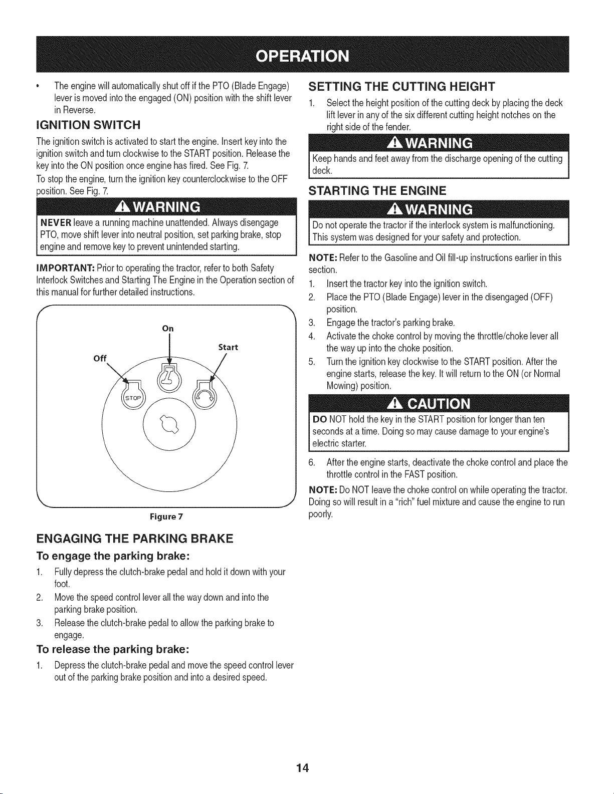
IGNITION SWITCH
The ignitionswitchis activatedto startthe engine.Insertkeyinto the
ignitionswitchandturnclockwiseto the STARTposition.Releasethe
keyintothe ON positiononceenginehasfired.SeeFig. 7.
Tostoptheengine,turnthe ignitionkeycounterclockwiseto the OFF
position.SeeFig. 7.
NEVER leavea runningmachineunattended.Alwaysdisengage
PTO,moveshift leverintoneutralposition,setparkingbrake,stop
_engne andremovekeyto preventunntendedstartng.
iMPORTANT: Priorto operatingthetractor,referto both Safety
InterlockSwitchesandStartingThe Enginein the Operationsectionof
thismanualfor furtherdetailedinstructions.
On
off
Start
Figure 7
SETTING THE CUTTING HEIGHT
1. Select the heightpositionof the cuttingdeck by placingthe deck
lift leverin anyof the sixdifferentcuttingheightnotcheson the
rightsideof the fender.
Keephandsandfeet awayfrom the dischargeopeningof the cutting
deck.
STARTING THE ENGINE
Donot operatethe tractorif the interlocksystemis malfunctioning.
Thissystemwasdesignedfor yoursafetyand protection.
NOTE: Referto the GasolineandOilfill-up instructionsearlierin this
section.
1. Insertthe tractorkey intothe ignitionswitch.
2. Placethe PTO(Blade Engage)leverin the disengaged(OFF)
position.
3. Engagethe tractor'sparkingbrake.
4. Activatethe chokecontrolby movingthethrottle/chokeleverall
the wayupinto thechokeposition.
5. Turnthe ignitionkey clockwiseto the STARTposition.Afterthe
enginestarts,releasethe key.Itwill returnto the ON(or Normal
Mowing)position.
DO NOT holdthe keyinthe STARTpositionfor longerthanten
secondsat atime. Doingso maycausedamageto yourengine's
electricstarter.
6. After the enginestarts,deactivatethe chokecontrolandplacethe
throttlecontrolin the FASTposition.
NOTE: Do NOTleavethe chokecontrolonwhileoperatingthe tractor.
Doingso will resultin a "rich"fuel mixtureand causetheengineto run
poorly.
ENGAGING THE PARKING BRAKE
To engage the parking brake:
1. Fullydepressthe clutch-brakepedaland holdit downwith your
foot.
2. Movethe speedcontrolleverall the way downand intothe
parkingbrakeposition.
3. Releasethe clutch-brakepedalto allowthe parkingbraketo
engage.
To release the parking brake:
1. Depressthe clutch-brakepedalandmovethe speedcontrollever
outof the parkingbrakepositionand intoa desiredspeed.
14
STOPPING THE ENGINE
Ifyou strikea foreignobject,stopthe engine,disconnectthe spark
plugwire(s)andgroundagainstthe engine.Thoroughlyinspectthe
machinefor anydamage.Repairthe damagebeforerestartingand
operating
If the bladesareengaged,placethe PTO(BladeEngage)leverin
the disengaged(OFF)position.
2. Turnthe ignitionkeycounterclockwiseto the STOPposition.
3. Removethekey from the ignitionswitchto preventunintended
starting.
DRIVING THE TRACTOR
Avoidsuddenstarts,excessivespeedandsuddenstops.
Do notleavethe seatof thetractorwithoutfirst placingthe PTO
(BladeEngage)leverin the disengaged(OFF) position,depressing
the brakepedaland engagingthe parkingbrake.If leavingthetractor
unattended,alsoturn the ignitionkeyoff andremovethe key.
Alwayslookdownandbehindbeforeandwhilebackingupto avoida
back-overaccident.
1. Depressthe clutch-brakepedalto releasethe parkingbrakeand
thenlet the pedalup.
2. Movethe throttleleverintothe FAST(rabbit) position.
3. Placethe shiftleverin eitherthe FORWARDor REVERSE
position.
IMPORTANT: DoNOTusethe shift leverto changethe directionof
travelwhenthe tractoris in motion.Alwaysusethe clutch-brakepedal
to bringthe tractorto a completestopbeforeshifting.
4. Releasethe parkingbrakebydepressingthe clutch-brakepedal
andpositioningthe speedcontrol leverin the desiredposition.
IMPORTANT: First-timeoperatorsshouldusespeedpositions1or
2. Becomecompletelyfamiliarwiththe tractor'soperationandcontrols
beforeoperatingthe tractorinhigherspeedpositions.
5. Releaseclutch-brakepedal slowlyto put unit intomotion.
6. Thelawntractorisbroughtto a stopbydepressingthe clutch-
brakepedal.
NOTE: Whenoperatingthe unitinitially,therewill be littledifference
betweenthe highesttwo speedsuntilafter the beltshaveseated
themselvesintothe pulleysduringthe break-inperiod.
WARNING!Beforeleavingthe operator'spositionfor any reason,
disengagethe blades,placethe shift leverinneutral,engagethe
parkingbrake,shutengineoff and removethe key.
1. Placethe shift leverin neutral,
2. Engagethe parkingbrake,
3. Shutengineoff and removethe key.Doingso will minimizethe
possibilityof havingyour lawn"browned"by hot exhaustfrom
yourtractor'srunningengine.
Ifunit stallswithspeedcontrolinhighspeed,or if unitwill not operate
with speedcontrolleverina low speedposition,proceedasfollows:
1. Placeshift leverin NEUTRAL.
2. Restartengine.
3. Placespeedcontrolleverinhighestspeedposition.
4. Releaseclutch-brakepedalfully.
5. Depressclutch-brakepedal.
6. Placespeedcontrolleverindesiredposition.
7. Placeshift leverin either FORWARDor REVERSE,andfollow
normaloperatingprocedures.
DRIVING ON SLOPES
Referto the SLOPEGAUGEinthe SafetyInstructionssectionof the
manualto helpdetermineslopeswhereyou mayoperatethis tractor
safely.
Donot mowon inclineswitha slopeinexcessof 15degrees(a rise
of approximately2-1/2feetevery 10feet).The tractorcouldoverturn
andcause seriousinjury.
•Mowupand down slopes,NEVERacross.
• Exerciseextremecautionwhenchangingdirectionon slopes.
Watchfor holes,ruts,bumps,rocks,or otherhiddenobjects.
Uneventerraincouldoverturnthe machine.Tallgrasscan hide
obstacles.
•Avoidturnswhendrivingon a slope.If a turnmustbe made,turn
downthe slope.Turningupa slopegreatlyincreasesthe chance
of a rollover.
•Avoidstoppingwhen drivingup a slope.If itis necessaryto stop
whiledrivingup a slope,start upsmoothlyandcarefullyto reduce
the possibilityof flippingthe tractoroverbackward.
ENGAGING THE BLADES
Engagingthe PTO(BladeEngage)transferspowerto the cuttingdeck
or other(separatelyavailable)attachments.Toengagethe blades,
proceedas follows:
1. Movethe throttle/chokecontrolleverto the FAST(rabbit)position.
2. Graspthe PTO(Blade Engage)leverand pivot it all the way
forwardinto theengaged(ON) position.
3. Keepthethrottleleverinthe FAST(rabbit)positionfor the most
efficientuseof the cuttingdeckor other(separatelyavailable)
attachments.
NOTE: Theenginewill automaticallyshutoff if the PTO(Blade
Engage)leveris movedintothe engaged(ON)positionwiththe shift
leverin Reverse.
IMPORTANT: Whenstoppingthe tractorfor any reasonwhileona
grasssurface,always:
15
MULCHING
A mulch kit is available as an attachment. Mulching is a process of
recirculating grass clippings repeatedly beneath the cutting deck.
The ultra-fine clippings are then forced back into the lawn where
they act as a natural fertilizer.
A mulchkitcan be purchased.See the ReplacementParts& Attach-
mentssectionof this manualfor moreinformation.
USING THE DECK LIFT LEVER
To raisethe cuttingdeck,movethe decklift leverto the left,then place
itin the notchbestsuitedfor yourapplication.Referto SettingThe
CuttingHeightearlierinthis Operationsection.
MOWING
Tohelpavoidbladecontactor a thrownobjectinjury,keepbystand-
ers,helpers,childrenandpets at least 75 feet fromthe machine
[wh e t s noperaton. Stop roachne f anyoneentersthearea.
Thefollowinginformationwill behelpfulwhen usingthecuttingdeck
withyourtractor:
Planyour mowingpatternto avoiddischargeof materialstoward
roads,sidewalks,bystandersandthe like.Also,avoiddischarging
materialagainsta wallor obstructionwhichmaycausedischarged
materialto ricochetbacktowardthe operator.
HEADLIGHTS
*The lampsareON wheneverthetractor'sengineis running.
o The lampsturn OFFwhenthe ignitionkeyismovedto the STOP
position.
Do not mowat highgroundspeed,especiallyifa mulchkit or
grasscollectorisinstalled.
Forbest resultsit isrecommendedthatthe firsttwo lapsbe cut
withthedischargethrowntowardsthe center.Afterthe first two
laps,reversethe directionto throwthe dischargeto the outside
for the balanceof cutting.Thiswillgive a betterappearanceto the
lawn.
Do notcut thegrasstoo short.Shortgrassinvitesweedgrowth
andyellowsquicklyindry weather.
Mowingshouldalwaysbe donewith the engineat full throttle.
• Underheavierconditionsitmaybenecessaryto go back overthe
cutareaa secondtime to geta cleancut.
• Do NOTattemptto mowheavybrushandweedsandextremely
tall grass.Yourtractorisdesignedto mowlawns,NOTclear
brush.
• Keepthe bladessharpand replacethe bladeswhenworn.Refer
to CuttingBladesinthe Servicesectionof thismanualfor proper
bladesharpeninginstructions.
16
MAINTENANCE SCHEDULE
Beforeperforminganytypeof maintenance/service,disengageall
controlsandstoptheengine.Waituntilallmovingpartshavecometo
acompletestop.Disconnectsparkplugwireandgrounditagainstthe
engineto preventunintendedstarting.Alwayswearsafetyglassesduring
operationorwhileperforminganyadjustmentsor repairs.
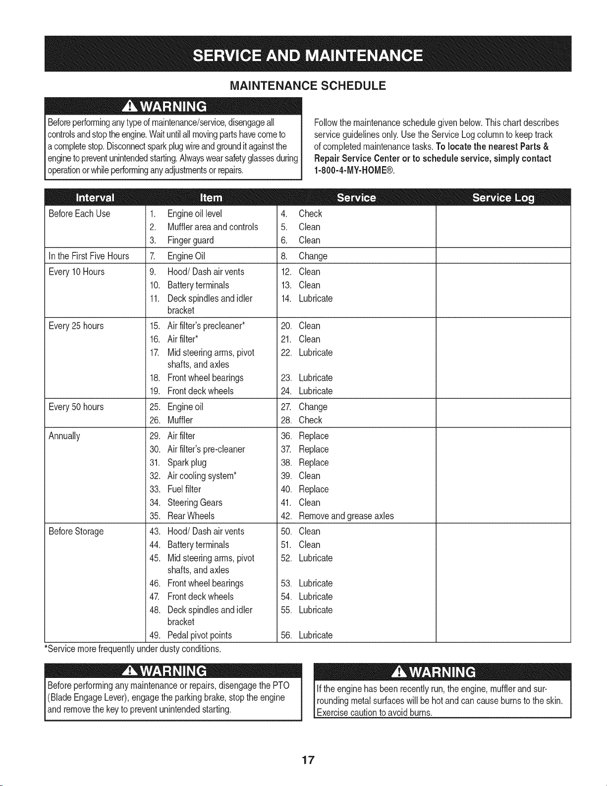
Followthe maintenanceschedulegivenbelow.Thischartdescribes
serviceguidelinesonly.Usethe ServiceLog columnto keeptrack
of completedmaintenancetasks.To locate the nearestParts&
Repair Service Centeror to scheduleservice,simplycontact
1-800-4-MY-HOME®.
BeforeEachUse
In the FirstFiveHours
Every10Hours
Every25 hours
Every50 hours
Annually
BeforeStorage
1. Engineoil level
2. Mufflerareaandcontrols
3. Fingerguard
7. EngineOil
9. Hood/Dashair vents
10. Batteryterminals
11. Deckspindlesand idler
bracket
15. Air filter'sprecleaner*
16. Air filter*
17. Midsteeringarms,pivot
shafts,andaxles
18. Frontwheelbearings
19. Frontdeckwheels
25. Engineoil
26. Muffler
29. Air filter
30. Air filter'spre-cleaner
31. Sparkplug
32. Air coolingsystem*
33. Fuelfilter
34. SteeringGears
35. RearWheels
43. Hood/Dashair vents
44. Batteryterminals
45. Midsteeringarms,pivot
shafts,andaxles
46. Frontwheelbearings
47. Frontdeckwheels
48. Deckspindlesand idler
bracket
49. Pedalpivotpoints
4. Check
5. Clean
6. Clean
8. Change
12. Clean
13. Clean
14. Lubricate
20. Clean
21. Clean
22. Lubricate
23. Lubricate
24. Lubricate
27. Change
28. Check
36. Replace
37. Replace
38. Replace
39. Clean
40. Replace
41. Clean
42. Removeandgreaseaxles
50. Clean
51. Clean
52. Lubricate
53. Lubricate
54. Lubricate
55. Lubricate
56. Lubricate
*Servicemorefrequentlyunderdustyconditions.
Beforeperformingany maintenanceor repairs,disengagethe PTO
(BladeEngageLever),engagethe parkingbrake,stopthe engine
andremovethe key to preventunintendedstarting.
If the enginehas beenrecentlyrun,the engine,mufflerandsur-
roundingmetalsurfaceswill behot and cancause burnsto the skin.
Exercisecautionto avoidburns.
17
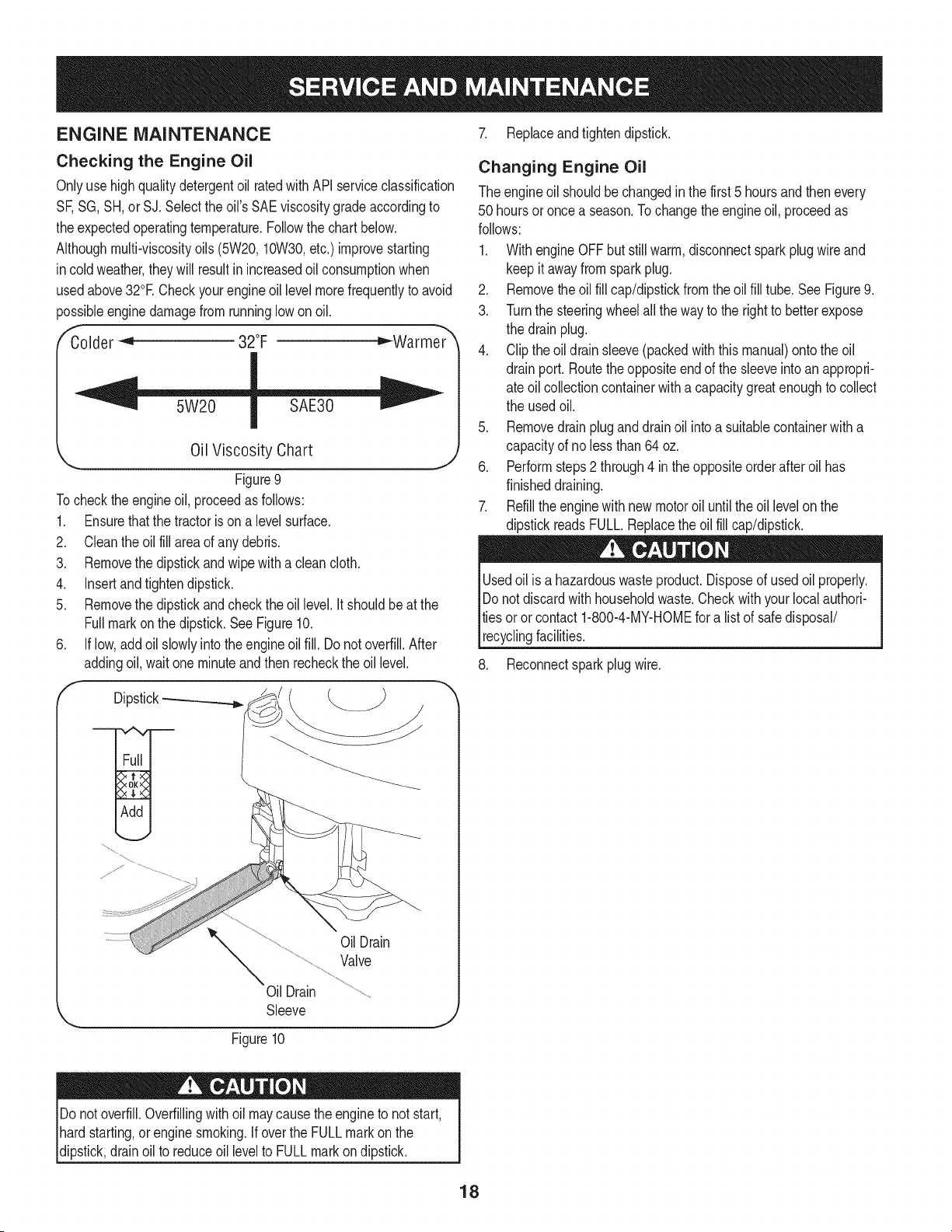
ENGINE MAINTENANCE
Checking the Engine Oil
Onlyuse highqualitydetergentoil ratedwith APIserviceclassification
SF,SG,SH,or SJ.Selectthe oil's SAEviscositygradeaccordingto
theexpectedoperatingtemperature.Followthe chartbelow.
Althoughmulti-viscosityoils (5W20,10W30,etc.)improvestarting
incold weather,theywill resultinincreasedoil consumptionwhen
usedabove32°E Checkyourengineoillevel morefrequentlyto avoid
possibleenginedamagefromrunninglowon oil.
fColder_ 32°F D"-Warmer
5W20
Oil Viscosity Chart
J
Figure9
Tocheckthe engineoil, proceedas follows:
1. Ensurethat the tractoris on a levelsurface.
2. Cleantheoil fill area of anydebris.
3. Removethe dipstickand wipe with a cleancloth.
4. Insertandtightendipstick.
5. Removethe dipstickand checkthe oil level.It shouldbe at the
Fullmarkonthe dipstick.SeeFigure10.
6. If low,add oil slowlyintothe engineoil fill. Do notoverfill.After
addingoil,wait oneminuteand thenrecheckthe oil level.
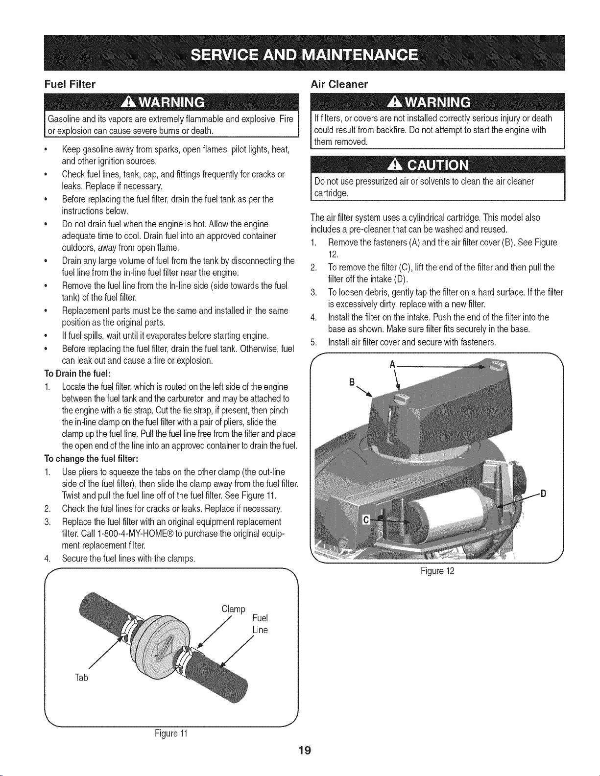
f
Dipstick_
7. Replaceandtightendipstick.
Changing Engine Oil
The engineoil shouldbe changedin the first 5 hoursand thenevery
50 hoursoronce a season.To changethe engineoil, proceedas
follows:
1. With engine OFFbut still warm,disconnectsparkplug wireand
keep it awayfromsparkplug.
2. Removethe oil fill cap/dipstickfrom theoil fill tube. See Figure9.
3. Turnthe steeringwheelall theway to the rightto betterexpose
the drainplug.
4. Clip theoil drain sleeve(packedwith this manual)ontothe oil
drainport. Routethe oppositeend of the sleeveintoan appropri-
ate oilcollectioncontainerwitha capacitygreatenoughto collect
the usedoil.
5. Removedrain plugand drainoil intoa suitablecontainerwith a
capacityof no lessthan64 oz.
6. Performsteps2 through4 in theoppositeorderafter oil has
finisheddraining.
7. Refillthe enginewith newmotoroil untilthe oil levelon the
dipstickreadsFULL.Replacethe oilfill cap/dipstick.
Usedoil is a hazardouswasteproduct.Disposeof usedoil properly.
Do notdiscardwithhouseholdwaste.Checkwithyour localauthori-
tiesoror contact 1-800-4-MY-HOMEfora listof safedisposal/
recyclingfacilities.
8. Reconnectsparkplug wire.
OilDrain
Valve
Oil Drain
Sleeve
Figure10
J
Do not overfill.Overfillingwithoil maycausetheengineto notstart,
hardstarting,or engine smoking.If overthe FULLmarkon the
dipstick,drainoil to reduceoil levelto FULLmarkon dipstick.
18
Fuel Filter Air Cleaner
Gasolineandits vaporsare extremelyflammableand explosive.Fire
or explosioncan causesevereburnsor death.
• Keepgasolineawayfromsparks,open flames,pilotlights,heat,
andotherignitionsources.
• Checkfuellines,tank,cap,andfittingsfrequentlyfor cracksor
leaks.Replaceif necessary.
• Beforereplacingthe fuel filter,drain the fueltank as per the
instructionsbelow.
• Do notdrainfuel whentheengineis hot.Allowtheengine
adequatetimeto cool. Drainfuel intoan approvedcontainer
outdoors,awayfromopenflame.
• Drainany largevolumeof fuelfromthe tankby disconnectingthe
fuellinefromthe in-linefuel filterneartheengine.
• Removethefuel linefromthe In-lineside (sidetowardsthe fuel
tank)of thefuel filter.
• Replacementpartsmustbe the sameandinstalledin the same
positionas the originalparts.
• If fuelspills,wait until it evaporatesbeforestartingengine.
• Beforereplacingthe fuel filter,drain the fueltank. Otherwise,fuel
can leakoutand causea fireor explosion.
To Drainthe fuel:
1. Locatethefuel filter,which isroutedonthe leftsideof theengine
betweenthefueltankandthecarburetor,and maybe attachedto
theenginewitha tie strap.Cutthetie strap,if present,thenpinch
thein-lineclamponthefuelfilterwitha pairof pliers,slidethe
clampupthefuelline. Pullthe fuellinefreefromthefilterandplace
theopenendof thelineintoanapprovedcontainerto drainthefuel.
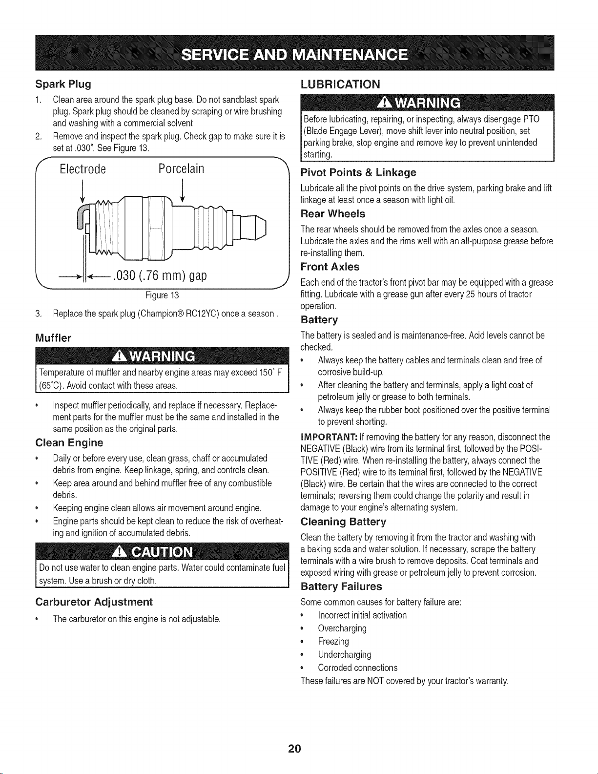
Tochangethe fuel filter:
1. Use pliersto squeezethe tabs on the otherclamp (theout-line
sidedthe fuel filter),thenslide theclampawayfromthefuel filter.
Twistandpull the fuelline off of the fuelfilter.SeeFigure11.
2. Checkthefuel linesfor cracksor leaks.Replaceif necessary.
3. Replacethefuel filter with an originalequipmentreplacement
filter.Call 1-800-4-MY-HOME®to purchasethe originalequip-
mentreplacementfilter.
Securethe fuel lineswiththe clamps.
.
f
Iffilters,or coversare notinstalledcorrectlyseriousinjury ordeath
could resultfrombackfire.Do not attemptto startthe enginewith
themremoved.
Donot use pressurizedair orsolventsto cleanthe aircleaner
cartridge.
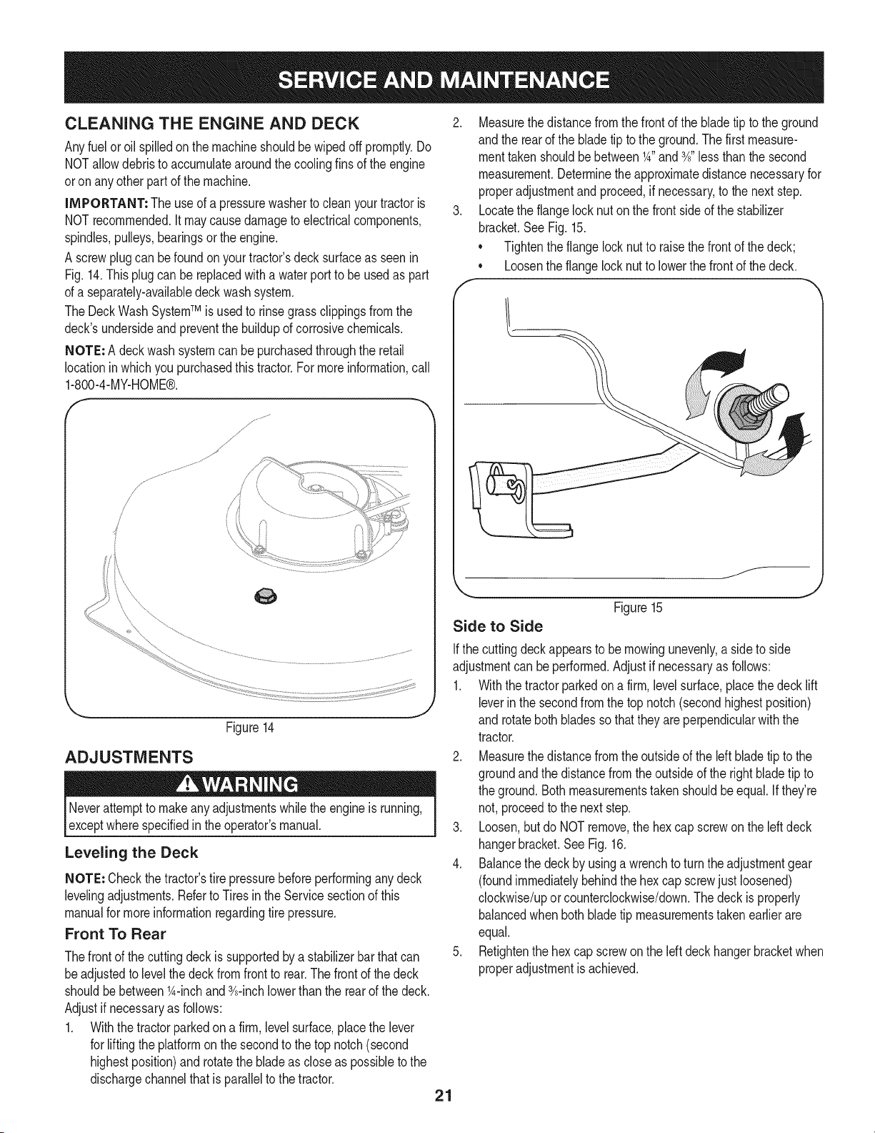
The airfiltersystemusesa cylindricalcartridge.This modelalso
includesa pre-cleanerthatcan bewashedand reused.
1. Removethe fasteners(A) and the air filtercover (B). See Figure
12.
2. To removethe filter (C), lift the end of the filterand thenpull the
filteroff the intake(D).
3. To loosendebris,gently tap thefilter on a hardsurface.If thefilter
isexcessivelydirty, replacewitha newfilter.
4. Installthe filter on the intake.Pushthe end of the filter intothe
baseas shown.Makesurefilter fits securelyin the base.
5. Installair filtercover and securewith fasteners.
A
B
Figure12
_J
Clamp Fuel
Line
Tab
Figure11
19
Spark Plug
1. Cleanareaaroundthe spark plug base.Do not sandblastspark
plug.Sparkplugshouldbecleanedby scrapingorwire brushing
andwashingwith a commercialsolvent
2. Removeand inspectthe sparkplug.Checkgapto makesureit is
setat .030".SeeFigure13.
Electrode Porcelain
.030 (.76 mm) gap
Figure13
J
3. Replacethe spark plug (Champion®RC12YC)oncea season.
Muffler
Temperatureof mufflerandnearbyengineareasmayexceed150° F
(65°0).Avoidcontact with theseareas.
• Inspectmufflerperiodically,and replaceif necessary.Replace-
mentpartsfor the mufflermustbethe sameand installedin the
samepositionas the originalparts.
Clean Engine
•Dailyor beforeeveryuse, cleangrass,chaffor accumulated
debrisfromengine.Keeplinkage,spring,andcontrolsclean.
• Keepareaaroundandbehindmufflerfreeof any combustible
debris.
• Keepingenginecleanallowsair movementaroundengine.
• Enginepartsshouldbe keptcleanto reducethe risk of overheat-
ingandignitionof accumulateddebris.
Do notuse waterto cleanengineparts.Watercouldcontaminatefuel
system.Usea brushordry cloth.
Carburetor Adjustment
• Thecarburetoronthis engineisnot adjustable.
LUBRICATION
Beforelubricating,repairing,or inspecting,alwaysdisengagePTO
(BladeEngageLever),move shiftleverinto neutralposition,set
parkingbrake,stopengineand removekeyto preventunintended
starting.
Pivot Points &Linkage
Lubricateall the pivot pointson the drivesystem,parkingbrakeand lift
linkageat leastoncea seasonwith lightoil.
Rear Wheels
The rearwheelsshouldberemovedfrom the axlesonce a season.
Lubricatethe axlesand the rims wellwith an all-purposegreasebefore
re-installingthem.
Front Axles
Eachendof thetractor'sfrontpivotbarmaybeequippedwitha grease
fitting.Lubricatewith a greasegunafter every 25 hoursof tractor
operation.
Battery
The batteryissealedand ismaintenance-free.Acidlevelscannotbe
checked.
• Alwayskeepthe batterycablesandterminalscleanandfree of
corrosivebuild-up.
Aftercleaningthe batteryandterminals,applya lightcoatof
petroleumjelly orgreaseto bothterminals.
• Alwayskeepthe rubberbootpositionedoverthe positiveterminal
to preventshorting.
iMPORTANT: If removingthe batteryfor any reason,disconnectthe
NEGATIVE(Black)wirefromitsterminalfirst,followedby the POSI-
TIVE(Red)wire.Whenre-installingthe battery,alwaysconnectthe
POSITIVE(Red)wireto its terminalfirst,followedbythe NEGATIVE
(Black)wire.Becertainthat the wiresare connectedto the correct
terminals;reversingthemcouldchangethe polarityandresult in
damageto your engine'salternatingsystem.
Cleaning Battery
Cleanthe batteryby removingitfromthe tractorandwashingwith
a bakingsodaandwatersolution.Ifnecessary,scrapethebattery
terminalswitha wirebrushto removedeposits.Coat terminalsand
exposedwiringwithgreaseor petroleumjellyto preventcorrosion.
Battery Failures
Somecommoncausesfor batteryfailureare:
Incorrectinitialactivation
• Overcharging
•Freezing
•Undercharging
•Corrodedconnections
Thesefailuresare NOTcoveredby yourtractor'swarranty.
20
CLEANING THE ENGINE AND DECK
Anyfuel oroil spilledonthe machineshouldbe wipedoffpromptly.Do
NOTallowdebristo accumulatearoundthecoolingfinsof the engine
oron anyotherpart of the machine.
IMPORTANT: The useof a pressurewasherto cleanyour tractoris
NOTrecommended.It maycausedamageto electricalcomponents,
spindles,pulleys,bearingsor theengine.
A screwplugcan befoundon yourtractor'sdecksurfaceas seenin
Fig.14.Thisplugcan be replacedwith a waterport to be usedas part
of a separately-availabledeckwash system.
The DeckWashSystemTM is used to rinsegrassclippingsfromthe
deck'sundersideand preventthe buildupof corrosivechemicals.
NOTE: A deckwash systemcan be purchasedthroughthe retail
locationinwhich you purchasedthis tractor.For moreinformation,call
1-800-4-MY-HOME®.
f
Figure14
ADJUSTMENTS
Neverattemptto makeanyadjustmentswhilethe engineis running,
exceptwherespecifiedin theoperator'smanual.
Leveling the Deck
NOTE: Checkthe tractor'stire pressurebeforeperforminganydeck
levelingadjustments.Referto Tiresin theService sectionof this
manualfor moreinformationregardingtire pressure.
Front To Rear
Thefrontof the cuttingdeckis supportedbya stabilizerbarthatcan
beadjustedto levelthe deckfrom front to rear.Thefront of the deck
shouldbebetween1A-inchand3A-inchlowerthanthe rearof the deck.
Adjustif necessaryas follows:
1. With thetractorparkedon a firm,levelsurface,placethe lever
for liftingthe platformon the secondto the top notch(second
highestposition)androtatethe bladeas close as possibleto the
dischargechannelthat is parallelto thetractor.
2. Measurethedistancefromthe front of the bladetip to theground
andthe rearof the bladetip tothe ground.Thefirst measure-
menttakenshouldbe between1A"and3A"less thanthe second
measurement.Determinetheapproximatedistancenecessaryfor
properadjustmentand proceed,if necessary,to the nextstep.
3. Locatethe flangelock nut on the front sideof the stabilizer
bracket.SeeFig. 15.
• Tightenthe flangelocknutto raisethe frontof the deck;
• Loosentheflangelock nutto lowerthe frontof thedeck.
Figure15
Side to Side
Ifthe cuttingdeckappearsto be mowingunevenly,a sideto side
adjustmentcan beperformed.Adjustif necessaryas follows:
1. With the tractorparkedon a firm, levelsurface,placethe deck lift
leverin the secondfromthe top notch(secondhighestposition)
and rotatebothbladesso thatthey are perpendicularwiththe
tractor.
2. Measurethedistancefromthe outsideof the left bladetip to the
groundandthe distancefrom the outsideof the rightblade tip to
the ground.Bothmeasurementstakenshouldbeequal.Ifthey're
not,proceedto the next step.
3. Loosen,but do NOTremove,the hex capscrewon the left deck
hangerbracket.SeeFig. 16.
4. Balancethe deck by usinga wrenchto turnthe adjustmentgear
(foundimmediatelybehindthe hex cap screwjustloosened)
clockwise/upor counterclockwise/down.Thedeck is properly
balancedwhenboth bladetip measurementstakenearlierare
equal.
5. Retightenthe hexcap screwon the left deck hangerbracketwhen
properadjustmentis achieved.
21
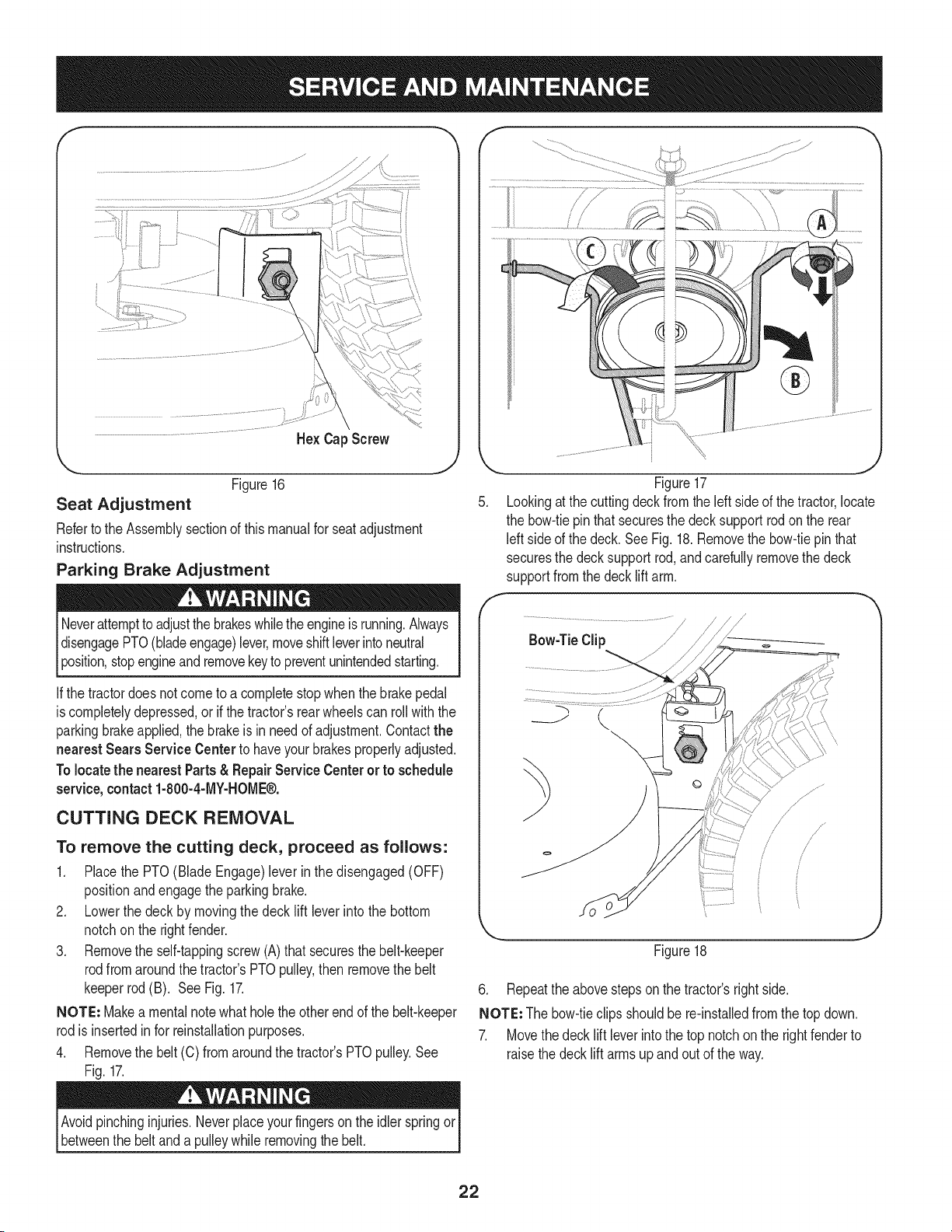
HexCap Screw
,J
Figure16
Seat Adjustment
Referto the Assemblysectionof thismanualfor seat adjustment
instructions.
Parking Brake Adjustment
Neverattemptto adjustthebrakeswhiletheengineis running.Always
disengagePTO(bladeengage)lever,moveshiftleverintoneutral
3osifion,stopengineandremovekeyto preventunintendedstarting.
the tractordoesnot cometo a completestopwhenthe brakepedal
is completelydepressed,or if the tractor'srearwheelscan rollwiththe
parkingbrakeapplied,the brakeis in needof adjustment.Contactthe
nearest Sears Service Center to haveyour brakesproperlyadjusted.
Tolocatethe nearest Parts& Repair Service Centeror to schedule
service,contact 1-800-4-MY-HOME®.
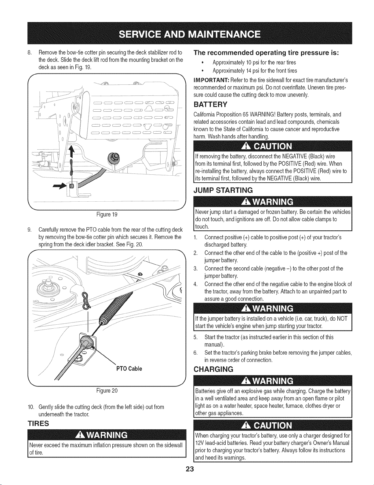
CUTTING DECK REMOVAL
To remove the cutting deck, proceed as follows:
1. Placethe PTO(Blade Engage) leverin the disengaged(OFF)
positionand engagetheparkingbrake.
2. Lowerthe deck by movingthe deck lift lever intothe bottom
notchon the rightfender.
3. Removethe self-tappingscrew(A)that securesthe belt-keeper
rodfromaroundthetractor's PTOpulley,then removethe belt
keeperrod(B). See Fig.17.
NOTE: Makea mentalnotewhat holethe otherend of the belt-keeper
rodis insertedin for reinstallationpurposes.
4. Removethe belt(C) fromaroundthe tractor'sPTOpulley.See
Fig. 17.
C
f
.J
Figure17
Lookingat thecuttingdeckfromthe leftside of thetractor,locate
the bow-tiepinthat securesthe deck support rod on the rear
left sideof the deck. SeeFig.18.Removethe bow-tiepinthat
securesthe decksupport rod,and carefullyremovethe deck
supportfromthe deck lift arm.
Bow-TieClip
/
/
/
//
Figure18
J
6. Repeatthe abovestepson the tractor'srightside.
NOTE: Thebow-tieclips shouldbe re-installedfromthe topdown.
7. Movethedeck lift leverintothe top notchon the rightfenderto
raisethedecklift armsupandout of the way.
Avoidpinchinginjuries.Neverplaceyour fingersonthe idler springor
betweenthe belt anda pulleywhile removingthe belt.
22
8. Removethebow-tiecotter pin securingthe deck stabilizerrod to
the deck.Slidethedecklift rodfromthe mountingbracketon the
deckas seenin Fig. 19.
f -,
........,j_!_ _;_ _ .....,
The recommended operating tire pressure is:
Approximately10psifor the reartires
Approximately14psi for thefronttires
IMPORTANT: Referto the tire sidewallfor exacttire manufacturer's
recommendedormaximumpsi.Donot overinfiate.Uneventirepres-
surecouldcausethe cuttingdeckto mowunevenly.
BATTERY
CaliforniaProposition65WARNING!Batteryposts,terminals,and
relatedaccessoriescontainleadandleadcompounds,chemicals
knownto the Stateof Californiato causecancerand reproductive
harm.Washhandsafterhandling.
If removingthe battery,disconnectthe NEGATIVE(Black)wire
fromitsterminalfirst,followedbythe POSFIVE(Red)wire.When
re-installingthe battery,alwaysconnectthe POSITIVE(Red)wireto
ts termna f rst,fo owedby the NEGATVE (Back)w re.
JUMP STARTING
.
Figure19
Carefullyremovethe PTOcablefromthe rearof the cuttingdeck
by removingthe bow-tiecotter pinwhich securesit. Removethe
springfromthe deckidlerbracket.SeeFig.20.
Neverjump starta damagedorfrozenbattery.Becertainthe vehicles
do nottouch,andignitionsare off. Do notallowcable clampsto
touch.
1. Connectpositive(+)cableto positivepost(+)of yourtractor's
dischargedbattery.
2. Connectthe otherend of the cableto the(positive+)postof the
jumperbattery.
3. Connectthe secondcable (negative-) to the otherpostof the
jumperbattery.
4. Connectthe otherend of the negativecableto the engineblockof
the tractor,awayfromthe battery.Attachto anunpaintedpartto
assurea goodconnection.
Figure20
10. Gentlyslidethe cuttingdeck(fromtheleft side)out from
underneaththe tractor.
TIRES
Neverexceedthemaximuminflationpressureshownonthe sidewall
of tire.
Ifthejumper batteryis installedon a vehicle (i.e.car, truck), do NOT
start the vehicle'senginewhenjump startingyourtractor.
5. Startthe tractor(as instructedearlierin this sectionof this
manual).
6. Setthe tractor'sparkingbrakebeforeremovingthejumpercables,
inreverseorderof connection.
CHARGING
Batteriesgive offan explosivegas whilecharging.Chargethe battery
in a wellventilatedareaand keepawayfroman openflameor pilot
light as ona waterheater,spaceheater,furnace,clothesdryeror
othergas appliances.
Whenchargingyourtractor'sbattery,useonlya chargerdesignedfor I
12Vlead-acidbatteries.Readyourbatterycharger_s Owner'sManualI
priorto chargingyourtractors battery.Alwaysfollowits instructions I
_andheed tswarnngs. J
23
Ifyour tractorhasnot beenputinto usefor anextendedperiodof time,
chargethe batteryas follows:
1. Setyour batterychargerto delivera max of 10amperes.
Ifyour batterychargeris automatic,chargethe batteryuntilthe
chargerindicatesthatchargingis complete.If the chargeris not
automatic,chargefor nofewerthaneight hours.
FUSE
One20 AMPfuseis installedin yourtractor'swiring harnessto protect
thetractor'selectricalsystemfromdamagecausedby excessive
amperage.
Ifthe electricalsystemdoesnot function,or yourtractor'senginewill
notcrank,first checkto becertainthatthe fusehasnot blown.It can
befoundat the rearof the unit, underneaththe fenderlocatedby the
battery.
Alwaysusea fusewiththe sameamperagecapacityfor replacement.
CUTTING BLADES
Shutthe engineoffand removeignitionkey beforeremovingthe
cuttingblade(s)for sharpeningor replacement.Protectyourhands
_byusng heavygoveswhengraspngthe bade.
Periodicallyinspectthe bladeand/or spindleforcracksor damage,
especiallyafter you'vestrucka foreignobject. Donot operatethe
machineuntil damagedcomponentsare replaced.
To removetheblades,proceedas follows.
1. Removethe deck from beneaththe tractor,(referto CuttingDeck
Removalearlierinthis section)thengentlyflip thedeckoverto
exposeitsunderside.
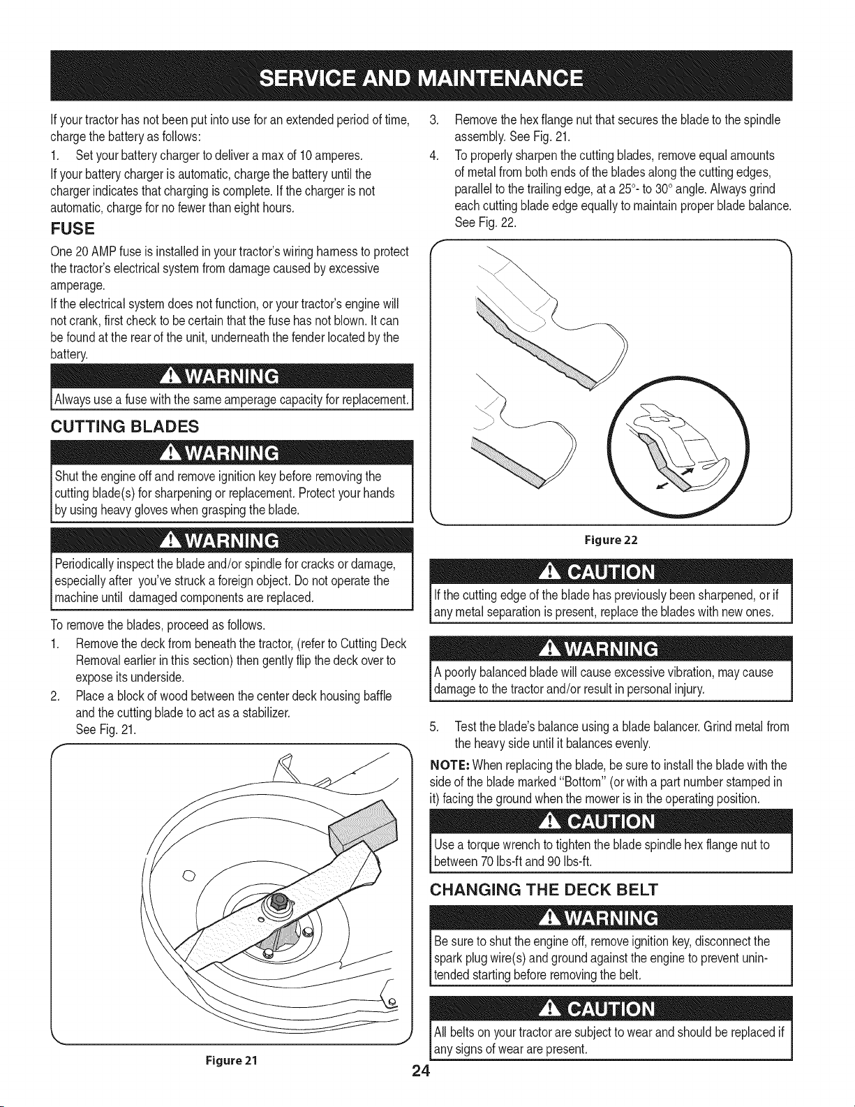
2. Placea blockof wood betweenthe centerdeck housingbaffle
andthe cuttingbladeto act asa stabilizer.
SeeFig. 21.
.
4.
Removethe hexflangenut thatsecuresthe bladeto the spindle
assembly.SeeFig.21.
To properlysharpenthecutting blades,removeequalamounts
of metalfrombothendsof the bladesalongthe cuttingedges,
parallelto the trailingedge,at a 250.to 300angle.Alwaysgrind
eachcuttingbladeedgeequallyto maintainproperblade balance.
See Fig.22.
Figure 22
Ifthe cuttingedgeof the bladehas previouslybeen sharpened,or if
any metalseparationis present,replacethe bladeswithnew ones.
A poorlybalancedbladewill causeexcessivevibration,maycause
damageto thetractorand/or resultin personalinjury.
5. Testthe blade'sbalanceusinga blade balancer.Grindmetalfrom
the heavysideuntil it balancesevenly.
NOTE: Whenreplacingthe blade,be sureto installthe bladewith the
side of the blademarked"Bottom" (orwitha partnumberstampedin
it) facingthe groundwhenthe moweris in the operatingposition.
Usea torquewrenchto tightenthe bladespindlehexflangenut to
between70Ibs-ft and 90 Ibs-ft.
CHANGING THE DECK BELT
Besureto shutthe engineoff, removeignitionkey,disconnectthe
sparkplugwire(s)and groundagainstthe engineto preventunin-
tendedstartingbeforeremovingthe belt.
All beltson yourtractoraresubjectto wearand shouldbereplacedif
Jany signsof wear arepresent.
Figure21 24
iMPORTANT: The V-beltfoundon yourtractoris speciallydesigned
to engageanddisengagesafely.A substitute(non-OEM)V-beltcan
bedangerousby notdisengagingcompletely.Fora properworking
machine,useidenticalequipmentbeltsas listedin the parts pagesof
thisOperator'sManual.
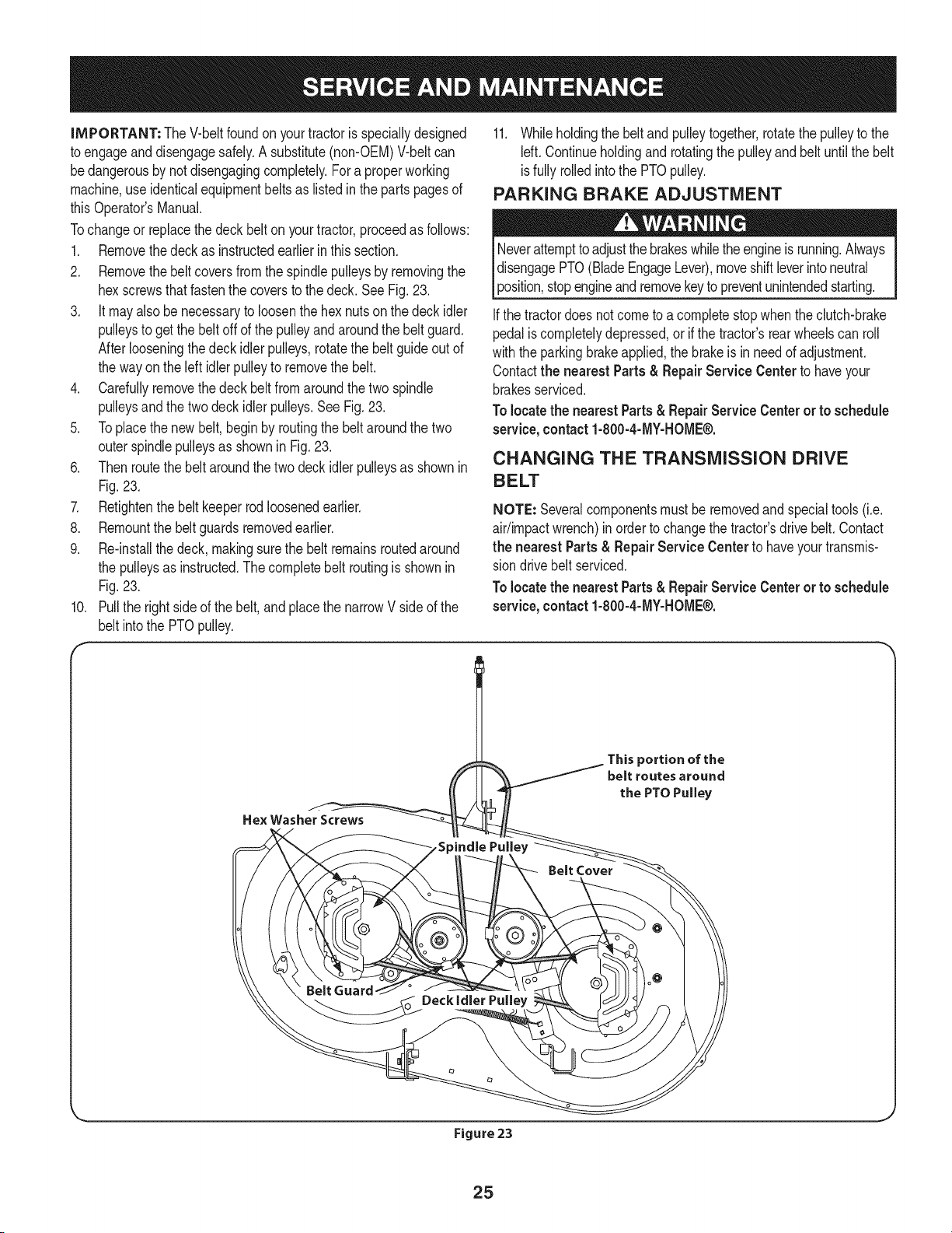
Tochangeor replacethedeckbelt onyourtractor,proceedas follows:
1. Removethedeck as instructedearlier in this section.
2. Removethebelt coversfrom the spindlepulleysby removingthe
hexscrewsthatfastenthe coversto the deck.SeeFig.23.
3. It mayalso benecessaryto loosenthe hex nutson thedeck idler
pulleysto getthe belt offof the pulleyand aroundthe belt guard.
Afterlooseningthe deckidlerpulleys,rotatethe belt guideout of
the wayon the left idlerpulleyto removethe belt.
4. Carefullyremovethe deck beltfrom aroundthe two spindle
pulleysand thetwo deckidlerpulleys.SeeFig.23.
5. Toplacethe newbelt, begin by routingthe beltaroundthe two
outerspindlepulleysas shownin Fig.23.
6. Thenroutethe beltaroundthe two deck idler pulleysas shownin
Fig.23.
7. Retightenthe belt keeperrod loosenedearlier.
8. Remountthebeltguardsremovedearlier.
9. Re-installthe deck,makingsurethe belt remainsroutedaround
the pulleysas instructed.Thecompletebelt routingis shownin
Fig.23.
Pullthe rightsideof thebelt, and placethe narrowV sideof the
belt intothe PTOpulley.
10.
F
11. Whileholdingthe belt andpulleytogether,rotatethe pulleyto the
Idt. Continueholdingand rotatingthe pulleyandbelt untilthe belt
isfully rolledintothe PTOpulley.
PARKING BRAKE ADJUSTMENT
Neverattempttoadjustthe brakeswhilethe engineis running.Always
disengagePTO(BladeEngageLever),moveshiftleverintoneutral
3osition,stopengineandremovekeyto preventunintendedstarting.
Ifthe tractordoesnotcometo a completestopwhentheclutch-brake
pedalis completelydepressed,or if the tractor'srearwheelscan roll
withthe parkingbrakeapplied,thebrakeis in need of adjustment.
Contactthe nearest Parts & Repair Service Center to haveyour
brakesserviced.
Tolocatethe nearestParts&RepairService Centeror to schedule
service,contact1-800-4-MY-HOME®.
CHANGING THE TRANSMISSION DRIVE
BELT
NOTE: Severalcomponentsmustbe removedandspecialtools(i.e.
air/impactwrench)in orderto changethetractor'sdrivebelt.Contact
the nearest Parts& Repair Service Centerto haveyourtransmis-
siondrivebelt serviced.
Tolocatethe nearestParts&RepairService Centeror to schedule
service,contact1-800-4-MY-HOME®.
This portion of the
belt routes around
the PTO Pulley
Figure 23
25
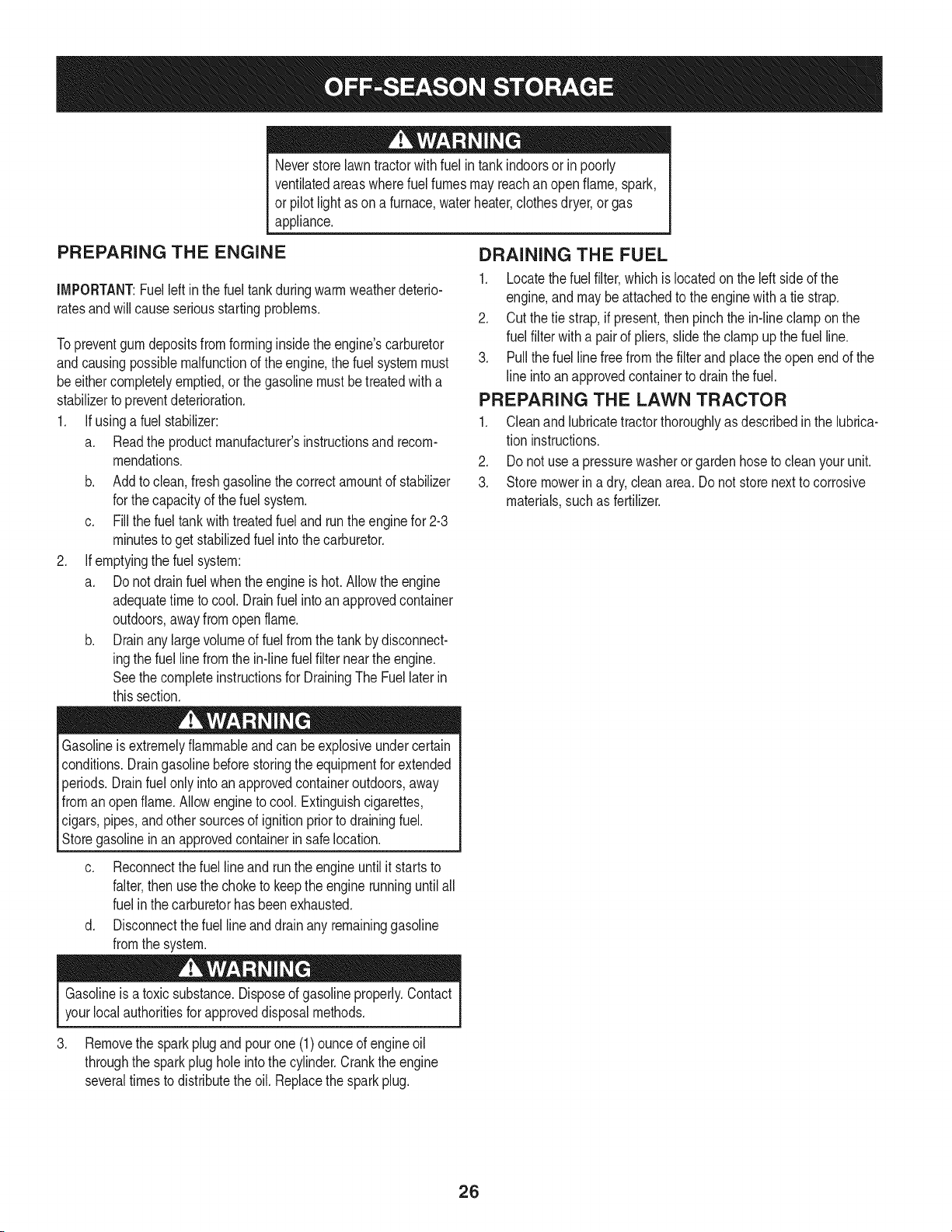
Neverstorelawntractorwithfuel intankindoorsor in poorly
ventilatedareaswherefuel fumesmayreachan openflame,spark,
or pilot lightas on a furnace,water heater,clothesdryer,or gas
appliance.
PREPARING THE ENGINE
IMPORTANT:Fuelleftinthe fueltankduringwarmweatherdeterio-
ratesandwillcauseseriousstartingproblems.
To preventgumdepositsfromforminginsidethe engine'scarburetor
andcausingpossiblemalfunctionof theengine,the fuelsystemmust
be eithercompletelyemptied,or the gasolinemustbetreatedwitha
stabilizerto preventdeterioration.
1. If usinga fuel stabilizer:
a. Readthe productmanufacturer'sinstructionsand recom-
mendations.
b. Add to clean, freshgasolinethe correctamountof stabilizer
for the capacityof the fuelsystem.
c. Fillthe fueltankwithtreatedfuel andrunthe enginefor 2-3
minutesto get stabilizedfuel intothe carburetor.
2. If emptyingthe fuel system:
a. Donot drainfuel whenthe engineis hot. Allowthe engine
adequatetimeto cool. Drainfuelinto anapprovedcontainer
outdoors,awayfromopen flame.
b. Drainany largevolumeof fuel from thetank by disconnect-
ingthe fuel linefrom the in-linefuel filternearthe engine.
Seethe completeinstructionsfor DrainingThe Fuellaterin
this section.
Gasolineis extremelyflammableandcan beexplosiveundercertain
conditions.Draingasolinebeforestoringthe equipmentfor extended
periods.Drainfuel onlyinto anapprovedcontaineroutdoors,away
froman openflame.Allowengineto cool.Extinguishcigarettes,
cigars,pipes,andothersourcesof ignitionpriorto drainingfuel.
Storegasolineinan approvedcontainerinsafelocation.
c. Reconnectthe fuel lineand run the engineuntilit startsto
falter,thenusethe choketo keepthe enginerunninguntilall
fuel inthe carburetorhas beenexhausted.
d. Disconnectthefuel line and drain any remaininggasoline
fromthe system.
DRAINING THE FUEL
1. Locatethe fuel filter,which is locatedon theleft sideof the
engine,and may be attachedto the enginewith a tie strap.
2. Cut the tie strap,if present,then pinchthe in-lineclamponthe
fuel filterwitha pairof pliers,slidethe clampupthe fuel line.
3. Pullthe fuel line freefrom the filterand placetheopen end of the
line intoanapprovedcontainerto drainthe fuel.
PREPARING THE LAWN TRACTOR
1. Cleanand lubricatetractorthoroughlyas describedin the lubrica-
tion instructions.
2. Donot usea pressurewasheror gardenhoseto cleanyour unit.
3. Store mowerin a dry,cleanarea. Do notstore nextto corrosive
materials,suchas fertilizer.
Gasolineis atoxic substance.Disposeof gasolineproperly.Contact
yourlocalauthoritiesforapproveddisposalmethods.
3. Removethe sparkplug and pour one (1) ounceof engineoil
throughthe sparkplugholeintothe cylinder.Crankthe engine
severaltimesto distributethe oil. Replacethe sparkplug.
26
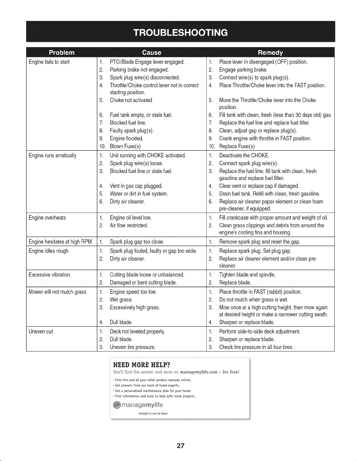
Enginefailsto start
Enginerunserratically
1. PTO/BladeEngageleverengaged.
2. Parkingbrakenotengaged.
3. Sparkplugwire(s)disconnected.
4. Throttle/Chokecontrollevernot in correct
startingposition.
5. Chokenotactivated
6. Fueltank empty,or stale fuel.
7. Blockedfuel line.
8. Faultysparkplug(s).
9. Engineflooded.
10. BlownFuse(s)
1. UnitrunningwithCHOKEactivated.
2. Sparkplugwire(s)loose.
3. Blockedfuel line or stalefuel.
4. Ventin gas cap plugged.
5. Wateror dirt in fuel system.
6. Dirtyair cleaner.
Engineoverheats 1. Engineoillevellow. 1.
2. Airflowrestricted. 2.
Enginehesitatesat high RPM 1. Sparkpluggaptoo close. 1.
Engineidles rough 1. Sparkplugfouled,faultyor gap too wide. 1.
2. Dirtyair cleaner. 2.
Excessivevibration
Mowerwill not mulchgrass
Unevencut
1. Cuttingblade looseor unbalanced.
2. Damagedor bent cuttingblade.
1. Enginespeedtoo low.
2. Wetgrass.
3. Excessivelyhighgrass.
4. Dullblade.
1. Decknot leveledproperly.
2. Dullblade.
3. Uneventire pressure.
1. Placeleverindisengaged(OFF)position.
2. Engageparkingbrake.
3. Connectwire(s) to sparkplug(s).
4. PlaceThrottle/Chokeleverintothe FASTposition.
5. MovetheThrottle/Chokeleverintothe Choke
position.
6. Filltank with clean,fresh (less than 30 days old) gas.
7. Replacethe fuel line and replacefuel filter.
8. Clean,adjustgap or replaceplug(s).
9. Crankenginewith throttlein FASTposition.
10. ReplaceFuse(s)
1. Deactivatethe CHOKE.
2. Connectsparkplugwire(s).
3. Replacethe fuel line;fill tank with clean,fresh
gasolineandreplacefuel filter.
4. Clearvent or replacecap if damaged.
5. Drainfuel tank. Refillwith clean,fresh gasoline.
6. Replaceair cleanerpaper elementor cleanfoam
pre-cleaner,if equipped.
Fillcrankcasewithproperamountandweightof oil.
Cleangrassclippingsanddebrisfrom aroundthe
engine'scoolingfinsandhousing.
Removesparkplugandresetthe gap.
Replacesparkplug.Set pluggap.
Replaceair cleanerelementand/orcleanpre-
cleaner.
1. Tightenbladeand spindle.
2. Replaceblade.
1. Placethrottlein FAST(rabbit)position.
2. Do notmulchwhen grassis wet.
3. Mowonceat a highcuttingheight,then mowagain
at desiredheightor makea narrowercuttingswath.
4. Sharpenor replaceblade.
1. Performside-to-sidedeckadjustment.
2. Sharpenor replaceblade.
3. Checktire pressurein all four tires.
NEED MORE HELP?
_m_[_ fhlJ lhe a:__wc_r_:md mo_e o_ m_agemy[_,f÷,,,cem - for h'ee[
Find this and aft your other product manuals online.
Get answers from our team of home experts.
Get a personalized maintenance ptan for your home.
I:ind information and toots to help with home projects.
27
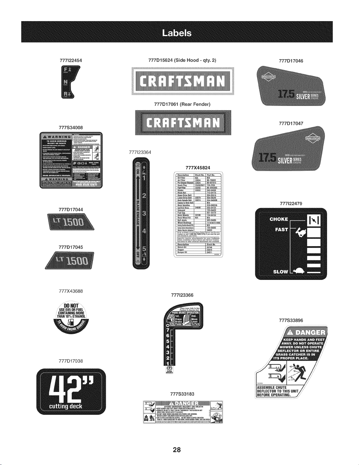
777122454 777D15624 (Side Hood -qty. 2) 777D17046
777D17061 (Rear Fender)
777S34008
777D17047
777123364
777D17044
777D17045
777X45824
777122479
777X43688
DOHOT...........
USE E85 UR FUEL
CO_TA|IIIHG _ORE
THAH 10% ETHANOL
W
777D17038
777123366
i(@)!
777S33183
_111!!11111111111_[_:___
......................N
777S33896
28

This page intentionally left blank. Use this page to make any notes regarding your tractor.
29
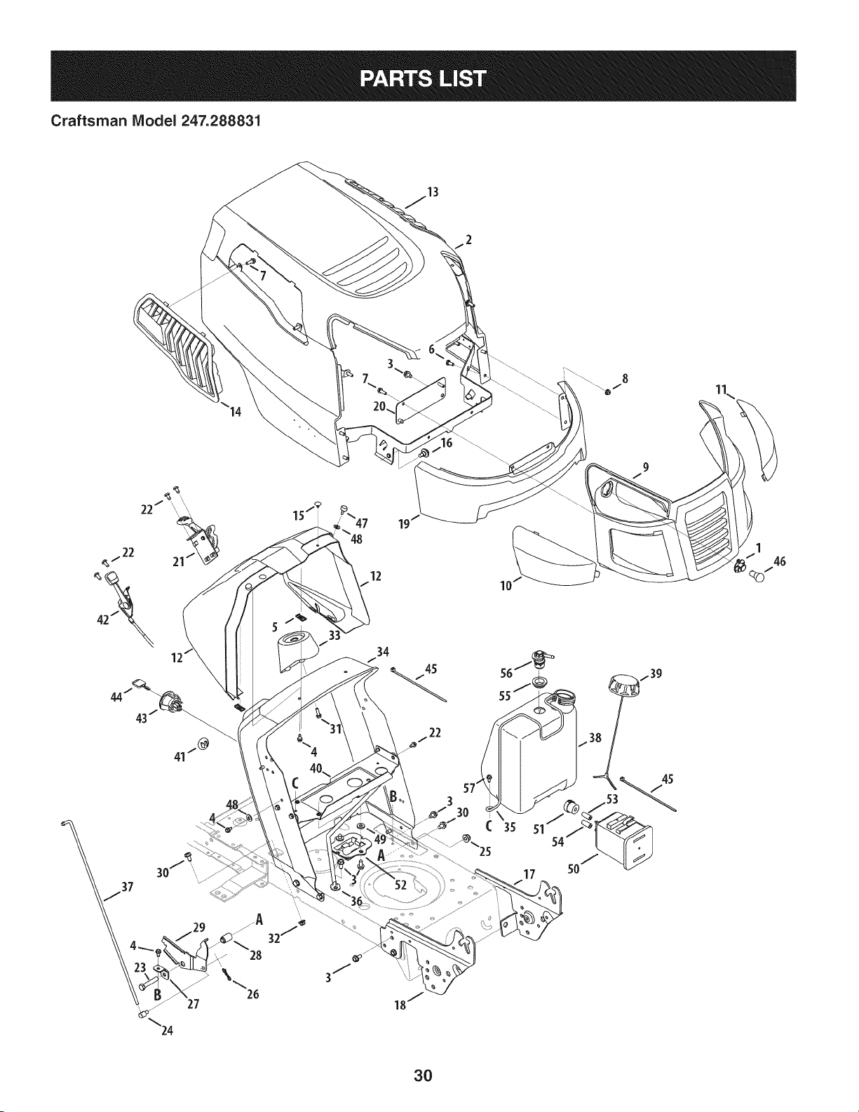
Craftsman IViodel 247.288831
19
10
35
54"
17
3O
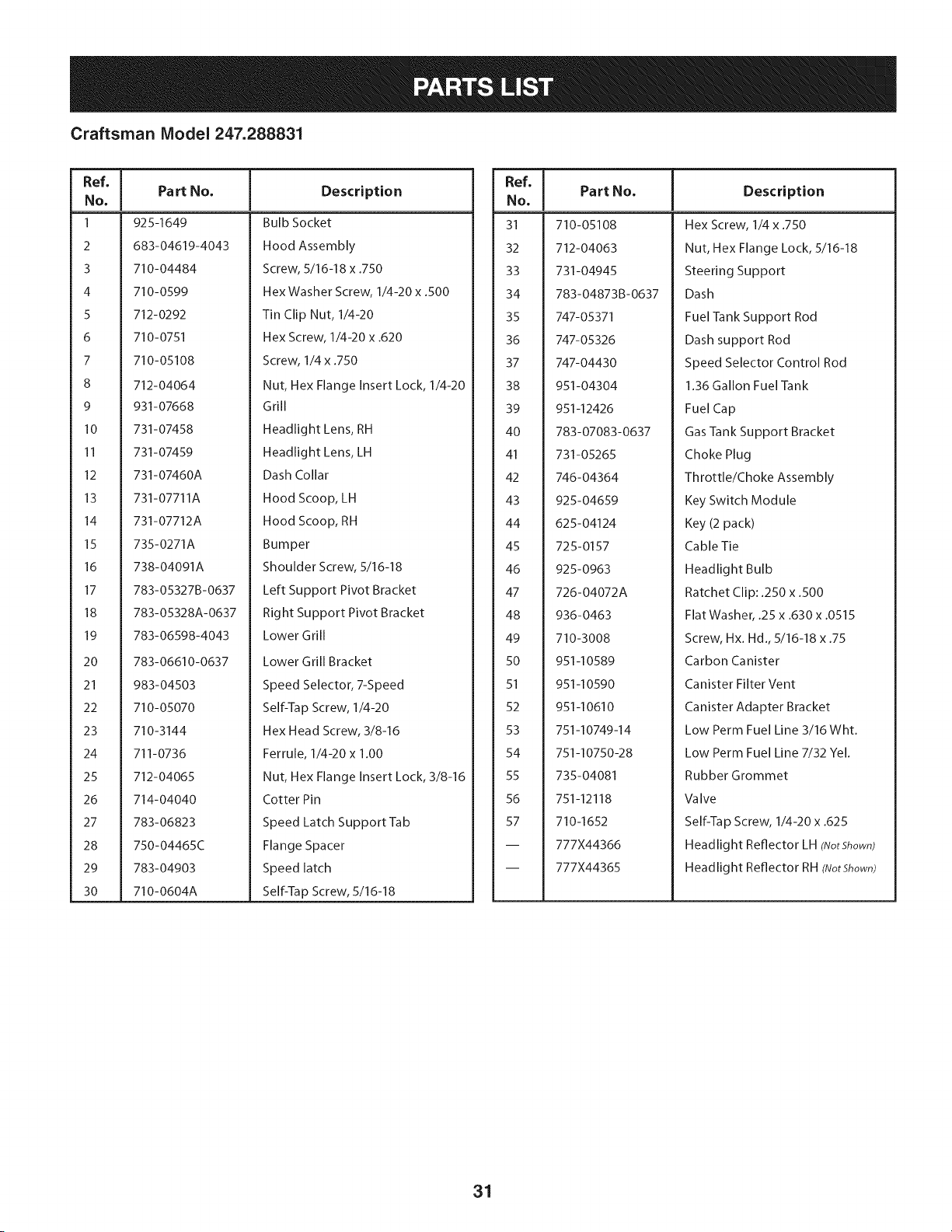
Craftsman IViodel 247.288831
Ref, I
No,
1 925-1649
2 683-04619-4043
3710-04484
4 710-0599
5 712-0292
6 710-0751
7 710-05108
8 712-04064
9 931-07668
I0 731-07458
11 731-07459
12 731-07460A
13 731-07711A
14 731-07712A
15 735-0271A
16 738-04091A
17 783-05327B-0637
18 783-05328A-0637
19 783-06598-4043
20 783-06610-0637
21 983-04503
22 710-05070
23 710-3144
24 711-0736
25 712-04065
26 714-04040
27 783-06823
28 750-04465C
29 783-04903
30 710-0604A
Part No, Description
Bulb Socket
Hood Assembly
Screw, 5/16-18 x .750
Hex Washer Screw, 1/4-20 x .500
Tin Clip Nut, 1/4-20
Hex Screw, 1/4-20 x .620
Screw, 1/4 x .750
Nut, Hex Flange Insert Lock, 1/4-20
Grill
Headlight Lens, RH
Headlight Lens, LH
Dash Collar
Hood Scoop, LH
Hood Scoop, RH
Bumper
Shoulder Screw, 5/16-18
Left Support Pivot Bracket
Right Support Pivot Bracket
Lower Grill
Lower Grill Bracket
Speed Selector, 7-Speed
Self-TapScrew, 1/4-20
Hex Head Screw, 3/8-16
Ferrule, 1/4-20 x 1.00
Nut, Hex Flange Insert Lock, 3/8-16
Cotter Pin
Speed Latch Support Tab
Flange Spacer
Speed latch
Self-TapScrew, 5/16-18
Ref, I
No,
31 710-05108
32 712-04063
33 731-04945
34 783-04873B-0637
35 747-05371
36 747-05326
37 747-04430
38 951-04304
39 951-12426
40 783-07083-0637
41 731-05265
42 746-04364
43 925-04659
44 625-04124
45 725-0157
46 925-0963
47 726-04072A
48 936-0463
49 710-3008
50 951-10589
51 951-10590
52 951-10610
53 751-10749-14
54 751-10750-28
55 735-04081
56 751-12118
57 710-1652
-- 777X44366
-- 777X44365
Part No, Description
Hex Screw, 1/4 x .750
Nut, Hex Flange Lock, 5/16-18
Steering Support
Dash
Fuel Tank Support Rod
Dash support Rod
Speed Selector Control Rod
1.36 Gallon Fuel Tank
Fuel Cap
Gas Tank Support Bracket
Choke Plug
Throttle/Choke Assembly
Key Switch Module
Key (2 pack)
Cable Tie
Headlight Bulb
Ratchet Clip: .250 x .500
Flat Washer, .25 x .630 x .0515
Screw, Hx. Hd., 5/16-18 x .75
Carbon Canister
Canister Filter Vent
Canister Adapter Bracket
Low Perm Fuel Line 3/16 Wht.
Low Perm Fuel Line 7/32 Yel.
Rubber Grommet
VaIve
Self-Tap Screw, 1/4-20 x .625
Headlight Reflector LH (IVotShown)
Headlight Reflector RH(IVotShown)
31
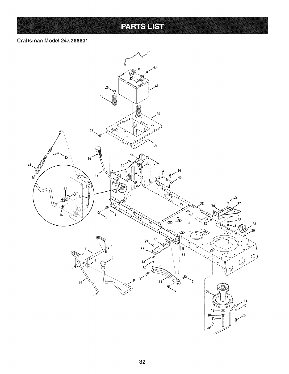
Craftsman Model 247.288831
36
22
21
14
12
39
3O
/29
27
38
2
32
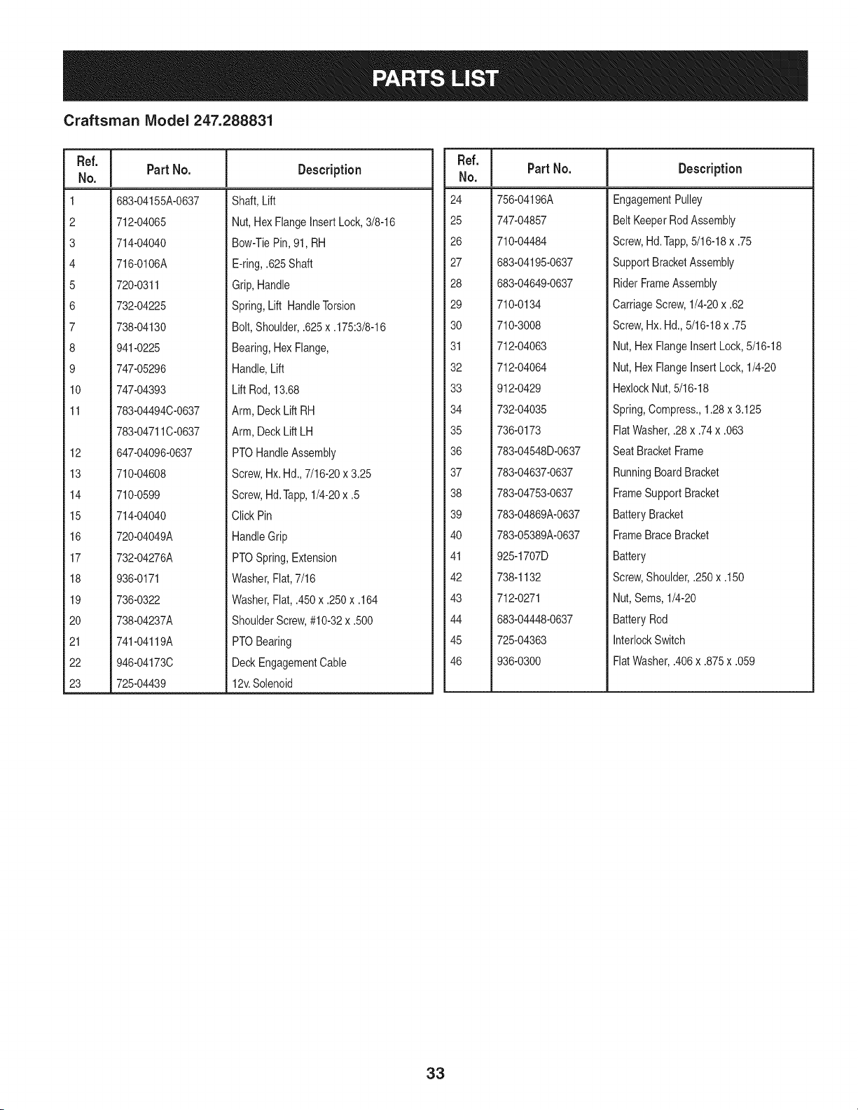
Craftsman IViodel 247.288831
Ref. I
No.
1 683-04155A-0637
2 712-04065
3 714-04040
4 716-0106A
5 720-0311
6 732-04225
7 738-04130
8 941-0225
9 747-05296
10 747-04393
11 783-04494C-0637
783-04711C-0637
12 647-04096-0637
13 710-04608
14 710-0599
15 714-04040
16 720-04049A
17 732-04276A
18 936-0171
19 736-0322
20 738-04237A
21 741-04119A
22 946-04173C
23 725-04439
Part No. Description
Shaft, Lift
Nut, HexFlangeInsertLock,3/8-16
Bow-TiePin,91, RH
E-ring,.625Shaft
Grip,Handle
Spring,Lift HandleTorsion
Bolt, Shoulder,.625x .175:3/8-16
Bearing,HexFlange,
Handle,Lift
Lift Rod,13.68
Arm, DeckLift RH
Arm, DeckLift LH
PTOHandleAssembly
Screw,Hx. Hd.,7/16-20x 3.25
Screw,Hd.Tapp,1/4-20x .5
Click Pin
HandleGrip
PTOSpring,Extension
Washer,Flat,7/16
Washer,Fiat, .450x .250x .164
ShoulderScrew,#10-32x .500
PTOBearing
DeckEngagementCable
12v.Solenoid
Ref. I
No.
24 756-04196A
25 747-04857
26 710-04484
27 683-04195-0637
28 683-04649-0637
29 710-0134
30 710-3008
31 712-04063
32 712-04064
33 912-0429
34 732-04035
35 736-0173
36 783-04548D-0637
37 783-04637-0637
38 783-04753-0637
39 783-04869A-0637
40 783-05389A-0637
41 925-1707D
42 738-1132
43 712-0271
44 683-04448-0637
45 725-04363
46 936-0300
Part No. Description
EngagementPulley
Belt KeeperRodAssembly
Screw,Hd.Tapp,5/16-18x .75
SupportBracketAssembly
RiderFrameAssembly
CarriageScrew,1/4-20x .62
Screw,Hx. Hd.,5/16-18x .75
Nut, HexFlangeInsert Lock,5/16-18
Nut, HexFlangeInsert Lock,1/4-20
HexlockNut,5/16-18
Spring,Compress.,1.28x 3.125
FlatWasher,.28x .74x .063
SeatBracketFrame
RunningBoardBracket
FrameSupportBracket
BatteryBracket
FrameBraceBracket
Battery
Screw,Shoulder,.250x .150
Nut,Sems, 1/4-20
BatteryRod
InterlockSwitch
FlatWasher,.406x .875x .059
33
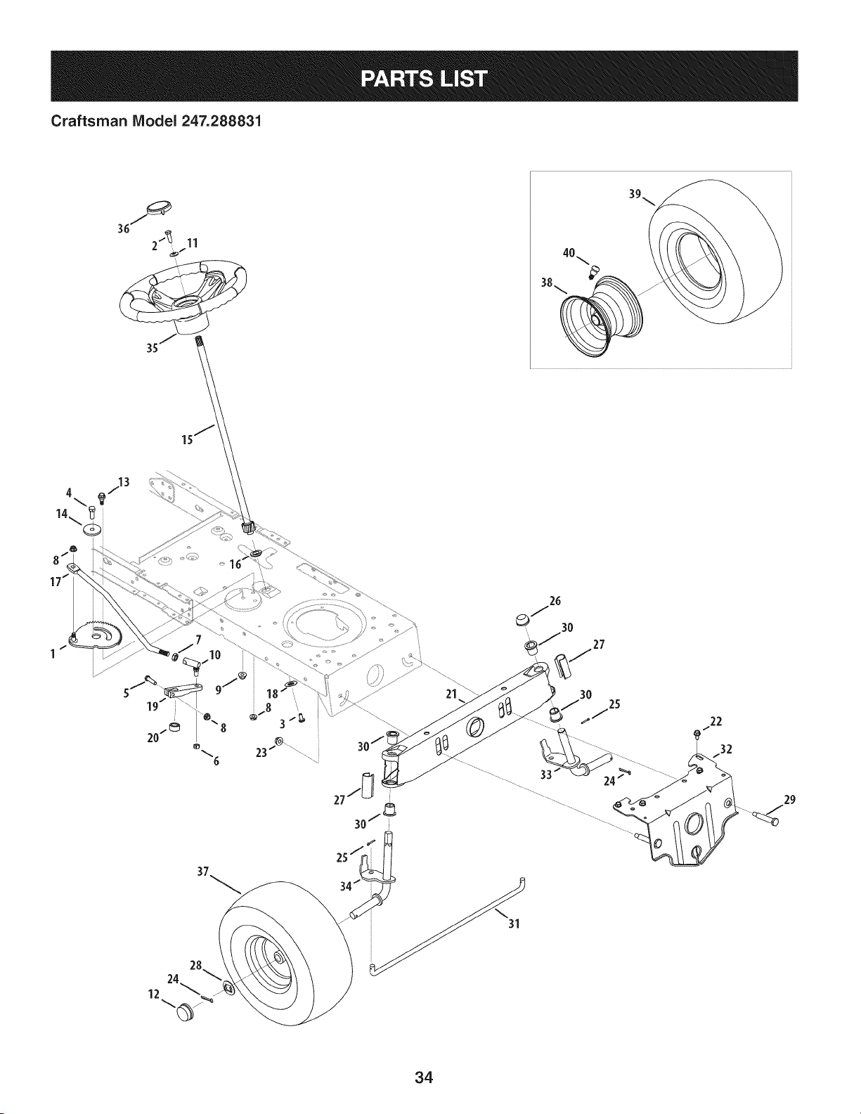
Craftsman Model 247.288831
21 3O 25
22
................ 33 / /_ ........................
34
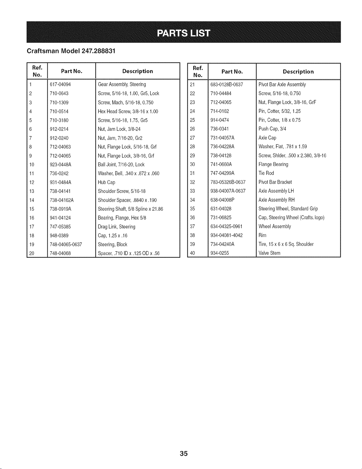
Craftsman IViodel 247.288831
Ref, I
No.
1 617-04094
2 710-0643
3 710-1309
4 710-0514
5 710-3180
6 912-0214
7 912-0240
8 712-04063
9 712-04065
10 923-0448A
11 736-0242
12 931-0484A
13 738-04141
14 738-04162A
15 738-0919A
16 941-04124
17 747-05385
18 948-0389
19 748-04065-0637
20 748-04068
Part No. Description
GearAssembly,Steering
Screw,5/16-18,1.00,Gr5,Lock
Screw,Mach,5/16-18,0.750
HexHeadScrew,3/8-16x 1.00
Screw,5/16-18,1.75,Gr5
Nut,JamLock,3/8-24
Nut,Jam,7/16-20,Gr2
Nut,FlangeLock,5/16-18,Grf
Nut,FlangeLock,3/8-16,Grf
BallJoint,7/16-20,Lock
Washer,Bell, .340x .872x .060
HubCap
ShoulderScrew,5/16-18
ShoulderSpacer,.8840x.190
SteeringShaft,5/8 Splinex 21.86
Bearing,Flange,Hex5/8
DragLink,Steering
Cap, 1.25x .16
Steering,Block
Spacer,.710ID x .125OD x .56
Ref, I
No.
21 683-0128B-0637
22 710-04484
23 712-04065
24 714-0162
25 914-0474
26 736-0341
27 731-04057A
28 736-04228A
29 738-04128
30 741-0660A
31 747-04299A
32 783-05326B-0637
33 938-04007A-0637
34 638-04008P
35 631-04028
36 731-06825
37 634-04325-0961
38 934-04081-4042
39 734-04240A
40 934-0255
Part No, Description
PivotBarAxle Assembly
Screw,5/16-18,0.750
Nut, FlangeLock,3/8-16,GrF
Pin, Cotter,5/32, 1.25
Pin, Cotter,1/8 x 0.75
PushCap,3/4
AxleCap
Washer,Flat,.781x 1.59
Screw,Shlder,.500x 2.380,3/8-16
FlangeBearing
Tie Rod
PivotBar Bracket
AxleAssemblyLH
AxleAssemblyRH
SteeringWheel,StandardGrip
Cap,SteeringWheel (Crafts.logo)
WheelAssembly
Rim
Tire, 15 x 6 x 6 Sq. Shoulder
ValveStem
35
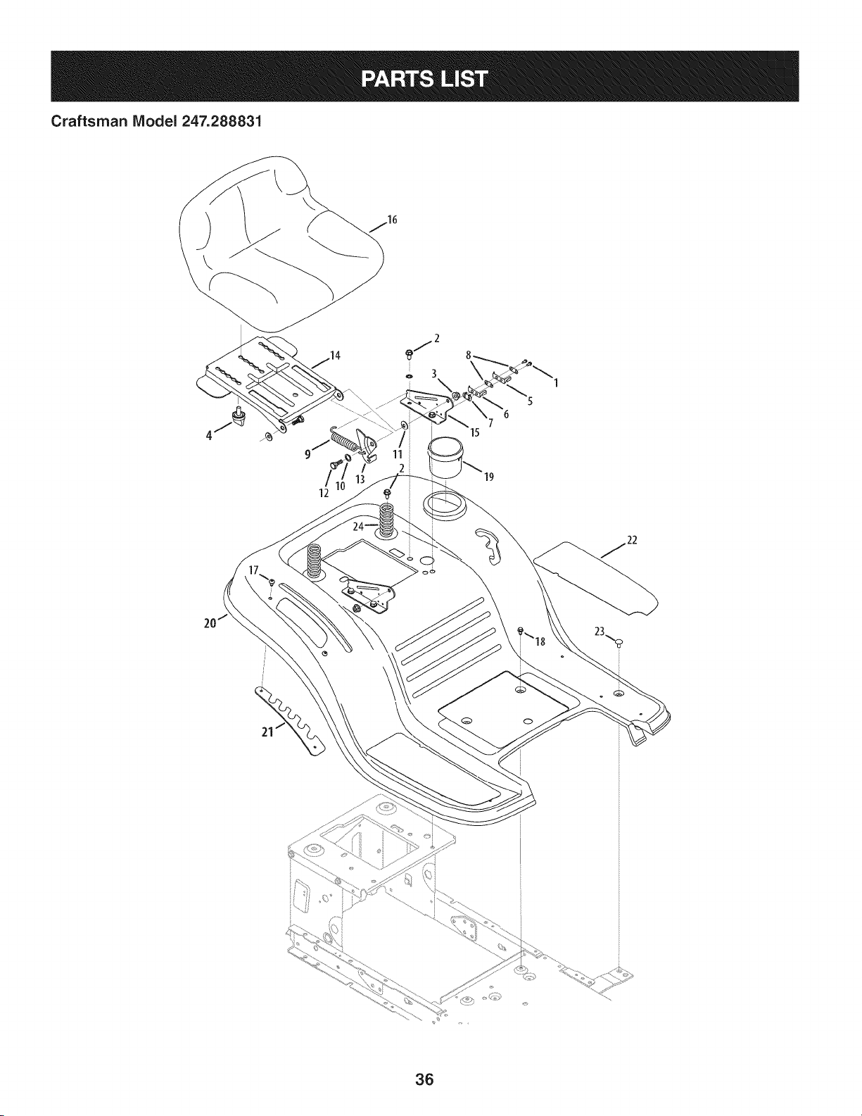
Craftsman IViodel 247.288831
\
36
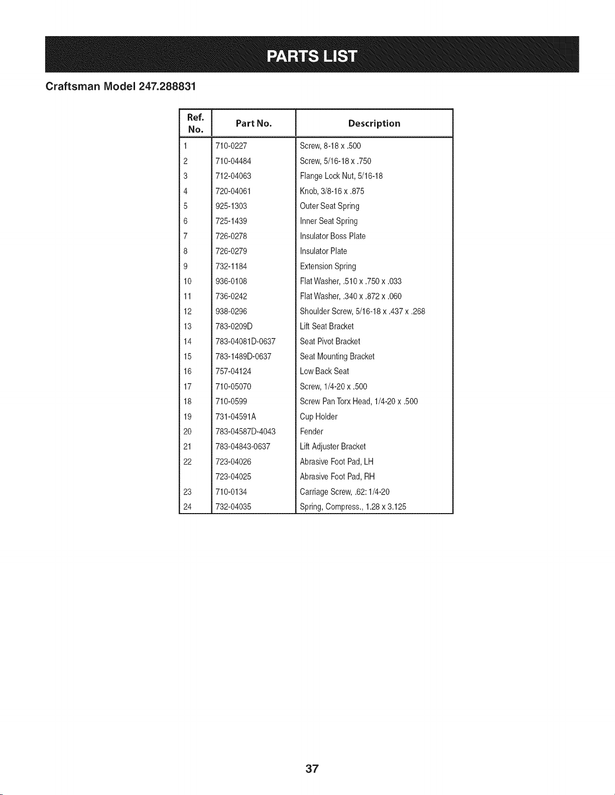
Craftsman IViodel 247.288831
Ref. I
No,
1 710-0227
2 710-04484
3 712-04063
4 720-04061
5 925-1303
6 725-1439
7 726-0278
8 726-0279
9 732-1184
10 936-0108
11 736-0242
12 938-0296
13 783-0209D
14 783-04081D-0637
15 783-1489D-0637
16 757-04124
17 710-05070
18 710-0599
19 731-04591A
20 783-04587D-4043
21 783-04843-0637
22 723-04026
723-04025
23 710-0134
24 732-04035
Part No. Description
Screw,8-18 x .500
Screw,5/16-18x .750
FlangeLockNut, 5/16-18
Knob,3/8-16x .875
OuterSeat Spring
InnerSeatSpring
InsulatorBossPlate
InsulatorPlate
ExtensionSpring
FiatWasher,.510x .750x .033
FlatWasher,.340x .872x .060
ShoulderScrew,5/16-18x .437x .268
Lift SeatBracket
Seat PivotBracket
Seat MountingBracket
Low BackSeat
Screw,1/4-20x .500
ScrewPanTorxHead,1/4-20x .500
Cup Holder
Fender
Lift AdjusterBracket
AbrasiveFoot Pad,LH
AbrasiveFoot Pad,RH
CarriageScrew,.62:1/4-20
Spring,Compress.,1.28x 3.125
37
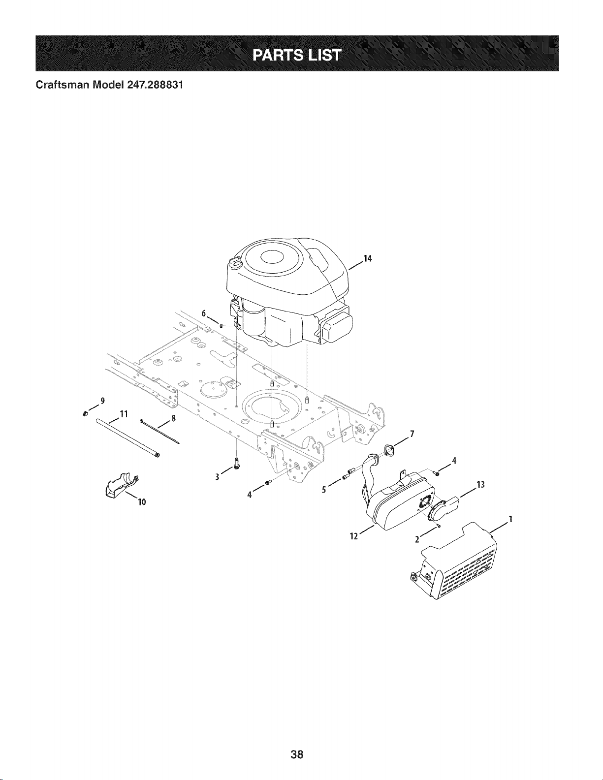
Craftsman IViodel 247.288831
38
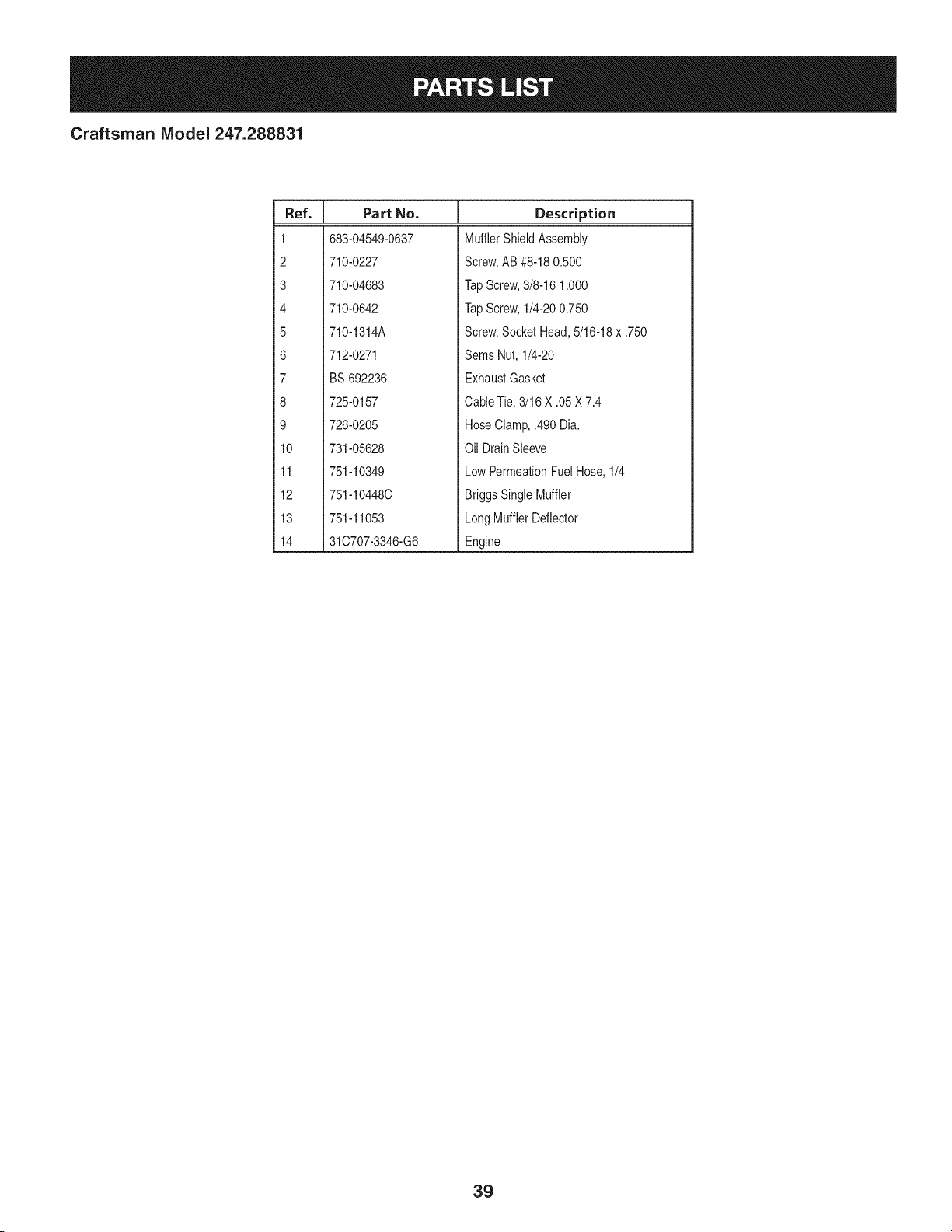
Craftsman IViodel 247.288831
I
Ref. I Part No.
1 683-04549-0637
2 710-0227
3 710-04683
4 710-0642
5 710-1314A
6 712-0271
7 BS-692236
8 725-0157
9 726-0205
10 731-05628
11 751-10349
12 751-10448C
13 751-11053
14 31C707-3346-G6
Description
MufflerShieldAssembly
Screw,AB #8-180.500
TapScrew,3/8-16 1.000
TapScrew,1/4-200.750
Screw,SocketHead,5/16-18x .750
Sems Nut, 1/4-20
ExhaustGasket
CableTie,3/16 X .05X 7.4
HoseClamp,.490 Dia.
Oil DrainSleeve
LowPermeationFuelHose,1/4
BriggsSingleMuffler
LongMufflerDeflector
Engine
39
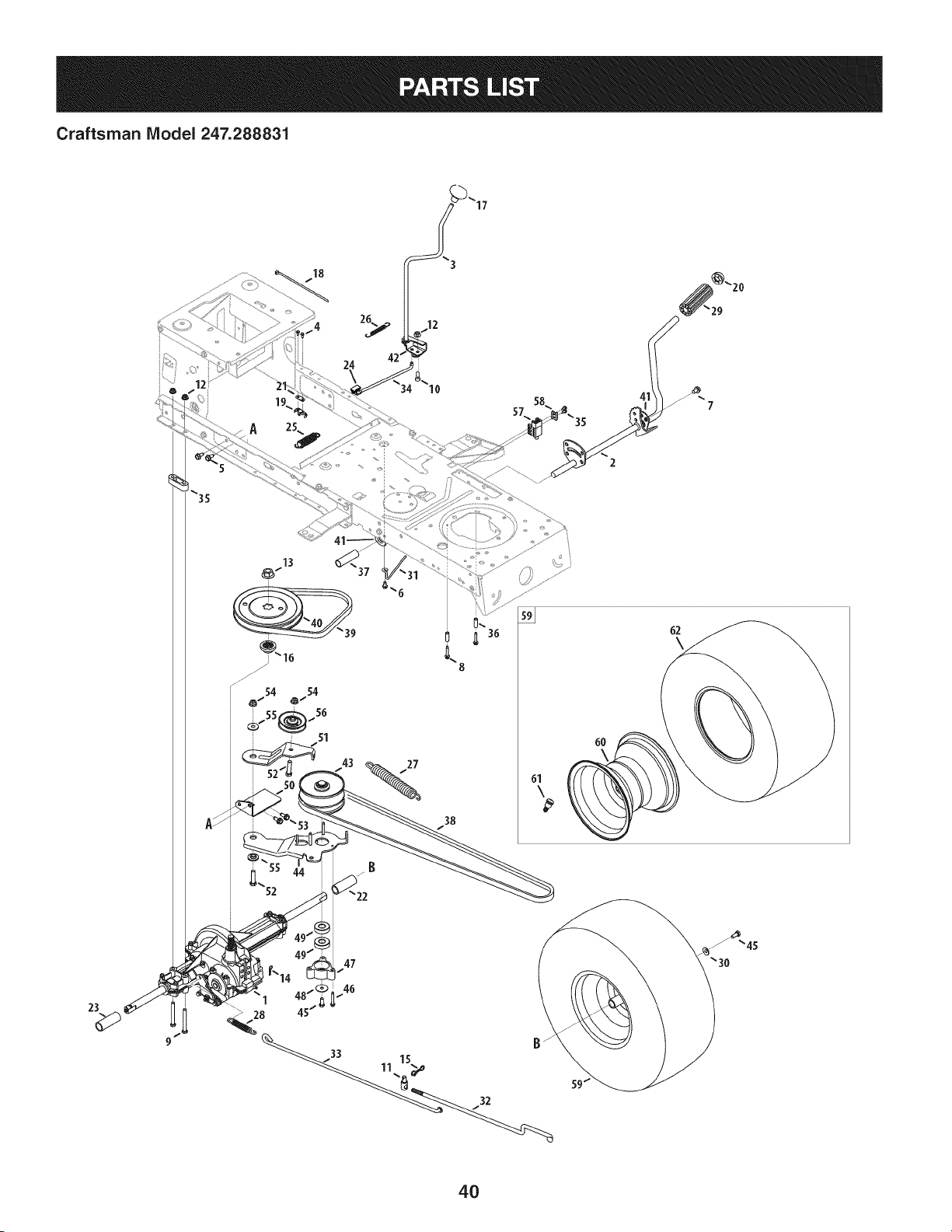
Craftsman IViodel 247.288831
18
8
27
38
6O
62
\
23
47
>28
1 15
4O

Craftsman IViodel 247.288831
Ref, I
NO,
1 918-04566
2 647-04034C-0637
3 647-04266
4 710-0227
5 710-04484
6 710-0599
7 710-0604A
8 710-0809
9 710-0176
10 710-3008
11 911-04075A
12 712-04063
13 712-0700
14 914-0209
15 714-04040
16 718-04407
17 720-04028
18 725-0157
19 725-1644
20 726-0214
21 926-0320
22 731-04602
23 731-04604
24 731-06894
25 732-04306
26 732-04488
27 732-04746
28 732-0716D
29 735-0239
30 736-0242
31 747-04969
32 747-05186
Part No. Description
TransmissionDriveAssembly
PedalAssembly
Shaft LeverAssembly
Screw,8-18:0.500
Screw,5/16-18x .750
Screw,1/4-20x 0.500
Screw,5/16-18 x 0.625
Screw,1/4-20x 1.250
HexScrew,5/16-18x 2.75
HexScrew,5/16-18x .75
Ferrule,3/8-24X .375DIA.
FlangelockNut, 5/16-18
FlangeNut, 9/16-18
Cotter Pin INT-.125DIA
Bow-TieCotter Pin
PulleyHub,5/8SPLINE
Shift Knob
CableTie
Short SpringSwitch
PushCap, 5/8
PlateInsulatorNut
Sleeve,.758x .821x 3.3125
Sleeve,.758x .821x 2.4375
Shift BearingPlate
Spring Extension,.80 OD x 3.28LG
Spring Extension,.38 OD x 3.25LG
Spring Extension,.94 OD x 6.75LG
Spring Extension,.59 OD x 4.00LG
FootPad,4.0 LONG
BellWasher,.340x .872x .060
Belt KeeperRod
VariableSpeedControl Rod
Ref. I
No,
33 747-05188
34 747-05244
35 738-04237A
36 750-0566A
37 750-0802
38 954-04249A
39 954-0241A
40 956-04002
41 783-04536B-0637
42 783-04595A
43 956-04015A
44 683-04206
45 710-0627
46 710-0778
47 718-04261
48 736-0362
49 941-0600
50 683-04176A
51 683-04207
52 710-0347
53 710-1260A
54 712-04065
55 938-0347
56 756-04325
57 725-04363
58 17962
59 634-04324
60 634-04369-4042
61 934-0255
62 734-04241
-- 725-04567G
Part No. Description
BrakeRod
Shift Rod
ShoulderScrew,#10-32x .500
Spacer,.260 x .375x 1.030LG
Spacer,.640 ID x .76 OD x 2.63
V Belt, 5L: 70.90 POLY
V Belt, 5L: 35.25 POLY
Trans.Pulley
PedalSupportBracket
ShaftAdjustBracket
VariableSpeed PulleyAssembly
BracketAssembly
HexScrew,5/16-24x .750
Screw,1/4-20x 1.500
BearingCup
FlatWasher,.330x 1.25x .06:HT
Ball Bearing,17x 40 x 12
TransmissionBracketAssembly
Idler BracketAssembly
HexScrew,3/8-16x 1.75
Screw,5/16-18x 0.750
FlangeLockNut, 3/8-16
ShoulderSpacer,.625ID x .169
Idler Pulley
SwitchInterlock
PlateSwitch
WheelAssembly,20x 8 x 8
RimAssembly
ValveStem
Tire, 20 x 8 x 8 Rd.Sh.
WiringHarness(NotShown)
41
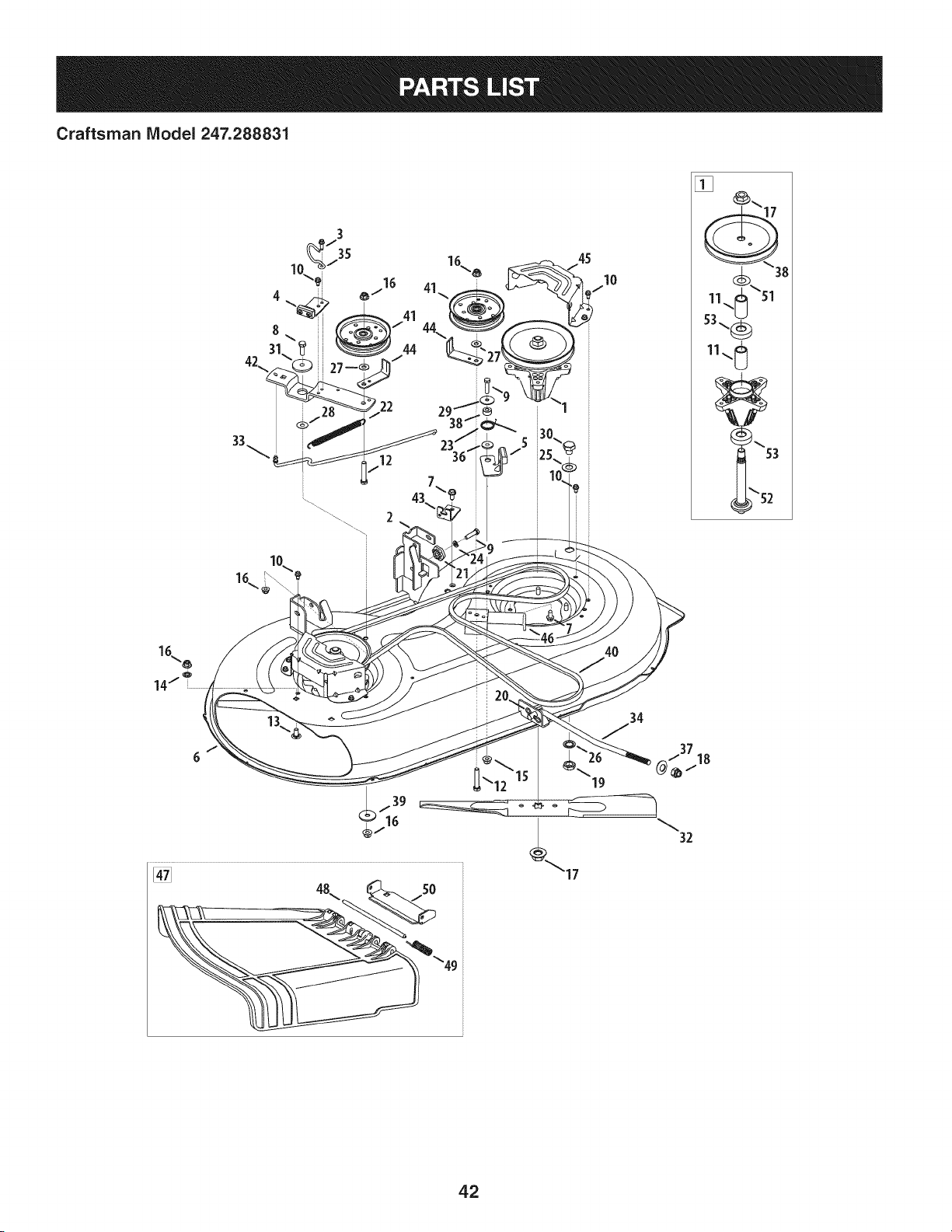
Craftsman IViodel 247.288831
19
42

Craftsman IViodel 247.288831
Ref, I
No,
1 918-04822A
2 683-0254B-0637
3 710-0642
4 983-04511
5 983-04525
6 983-04570-0637
7 710-04484
8 710-3005
9 710-0528
10 710-0599
11 750-04936
12 710-3144
13 710-3178
14 712-0229
15 712-04063
16 712-04065
17 712-0417A
18 712-04243
19 912-0641
20 714-04043
21 917-04074
22 932-0384
23 732-04840
24 936-0119
25 736-0187
26 736-0225
27 736-0262
Part No. Description
SpindlePulleyAssembly
DeckHangerBracketAssembly
Screw,1/4-20x .750
BrakeAssembly
BrakeAssembly
Deck
Screw,5/16-18x .750
Screw,3/8-16x 1.25
HexScrew,5/16-18x 1.25
Screw,1/4-20x .500
Spacer,.792x 1.060x 1.860
HexHeadScrew,3/8-16
CarriageBolt, 3/8-16x .75
PushNut,3/8
FlangelockNut, 5/16-18
FlangelockNut, 3/8-16
FlangeNut, 5/8-18
FlangelockNut, 1/2-13
HexNut,M16- 1.5
CotterPin, Bow-Tie
DeckAdjusterGear
ExtensionSpring,.62x 6.12
TorsionSpring,1.0 x 1.17
LockWasher,5/16
FiatWasher,.64x 1.24x .06
FlatWasher,.5/8Int.Tth.
FiatWasher,.385x .870x .092
Ref. I
NO,
28 936-0344
29 736-0362
30 738-04146
31 738-04162A
32 942-04308
33 747-05105B
34 747-05141A
35 747-05323
36 748-04272
37 748-04069
38 956-1227
39 936-3039
40 954-04060B
41 756-04129B
42 783-05946
43 783-06243-0637
44 783-06368A-0637
45 783-06424A-0637
46 783-06643-0637
47 631-04288
48 711-04847B
49 732-04372
50 783-06074A
51 936-0351
52 738-1186A
53 941-0919A
Part No. Description
FlatWasher,.385x 1.0x .030
FlatWasher,.330x 1.25x .06
Bolt Plug,M16x 1.5
ShoulderSpacer,.8840x .190
CuttingBlade,21.23":2 in 1
BrakeControlRod
DeckLift Rod
Belt KeeperRod
ShoulderSpacer
DeckLift PivotCup
DeckPulley,6.3dia.
FlatWasher,.406x 1.50x .105
V-TypeBelt, 96.5
Idler Pulley,4.25Diameter
Idler PivotBracket
DeckCableEngagementBracket
Belt PulleyGuard
DeckBelt Cover
DeckSupportBracket
ChuteDeflectorAssembly
Hinge Pin
TorsionSpring,.44 x 2.0
ChuteBracket
FlatWasher,.760x 1.50
SpindleShaft
Ball Bearing,.787x 1.85x .551
43
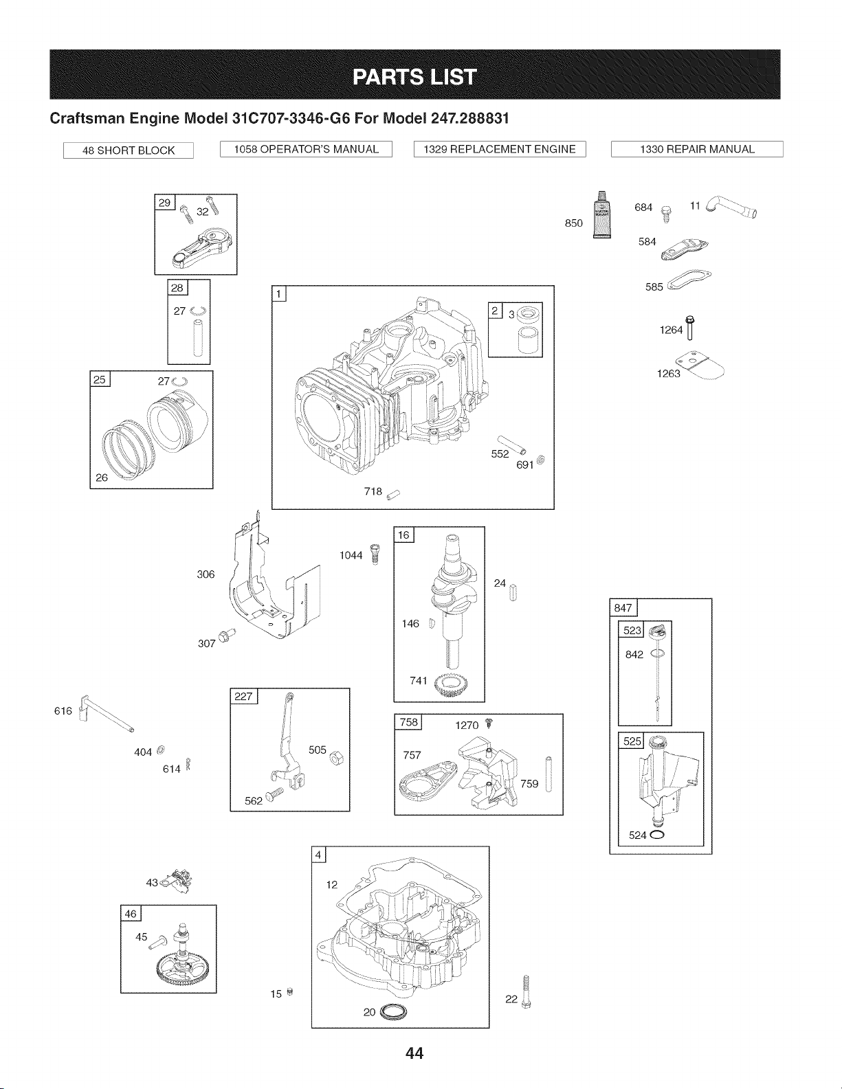
Craftsman Engine Model 310707=3346=G6 For Model 247.288831
48 SHORT BLOCK 1058 OPERATOR'S MANUAL [ 1329 REPLACEMENT ENGINE ] 1330 REPAIR MANUAL
616
129 1_ _¢\
_ 32_}_
/
25_ 27
q
ii
306 i J
,4_,
,\
307 @_
552<-_
691 @
718 d/"
_..-.(:::J
146 _'
741
24 _
1270
757
759
85O
f T"-_.
684 @ 11 _ .......:_._:@
584
585_ _
1264 I_
s__
842 c,_9
s__JG
5240
Q
15 @
44
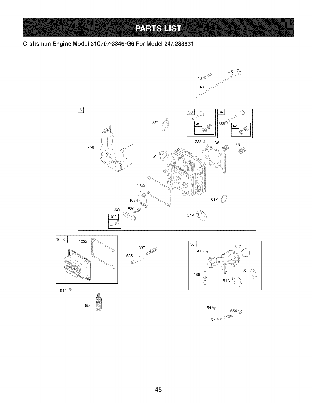
Craftsman Engine Model 31C707-3346-G6 For Model 247.288831
lO26_/_
s _
883
51
35
1022
1o22
337 501 617
914 ©'9
85O 54% 654 _)
53 d:*-;_::::$S'i_
45
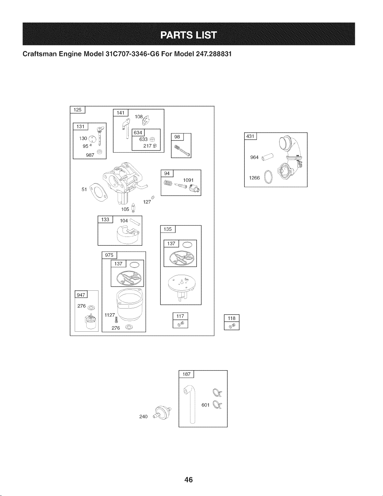
Craftsman Engine IViodel 31C707-3346-G6 For IViodel 247.288831
130 :-'_
95 _ _
987
_ lO_
i633 _
2179
51
105
Q
127
1127__
276 _)
1091
964 ........
' i
24O
6Ol _
i
46
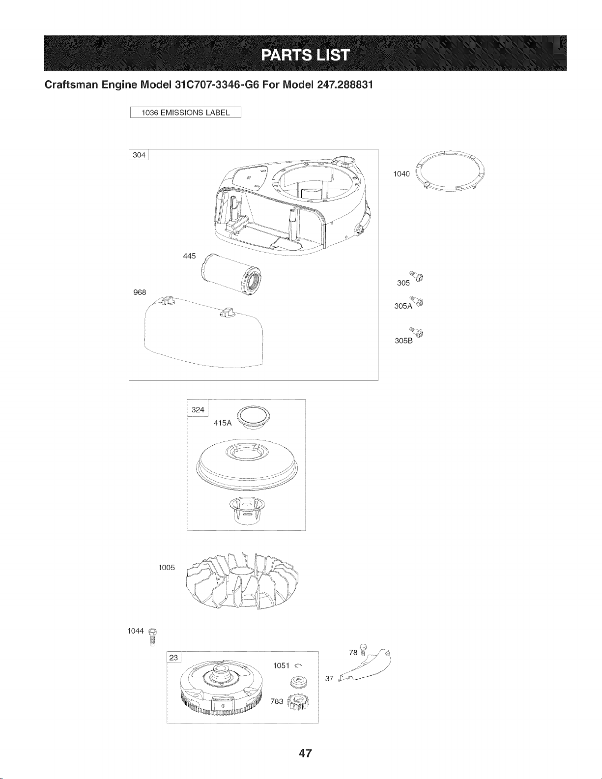
Craftsman Engine Model 31C707=3346=G6 For Model 247.288831
1036 EMiSSiONS LABEL
968
445
\\
I
2
1040
305 _
305AQ_
305B
324
415A
,./:,,;\ \"_{,":,_j !/ 4_7><_
lOOS C-;>..._\\d_-_t ib.j,:Q _
1044
78 b_ d_
37 _
47
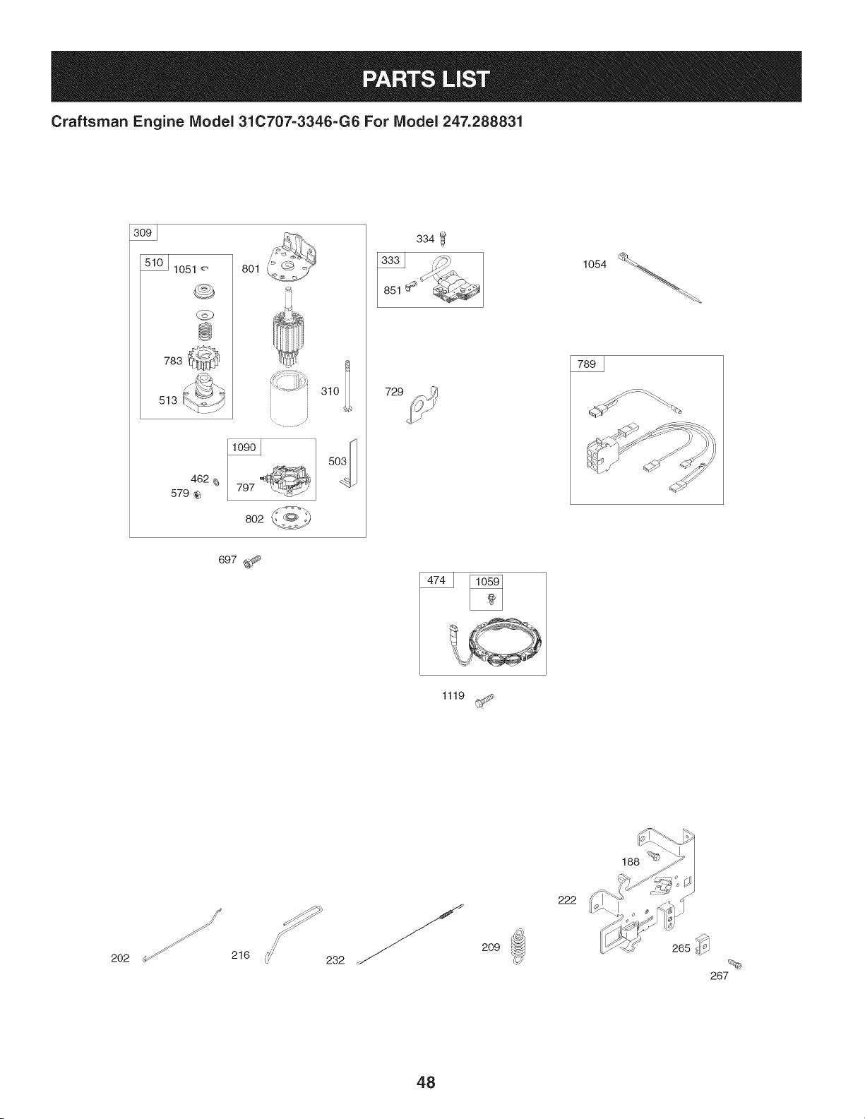
Craftsman Engine IViodel 31C707-3346-G6 For IViodel 247.288831
lO51 8ol
@
783
513
462
579
. i '¸
797
802
729
334
697 _
1119
188 _
202 216 232
209
222
48
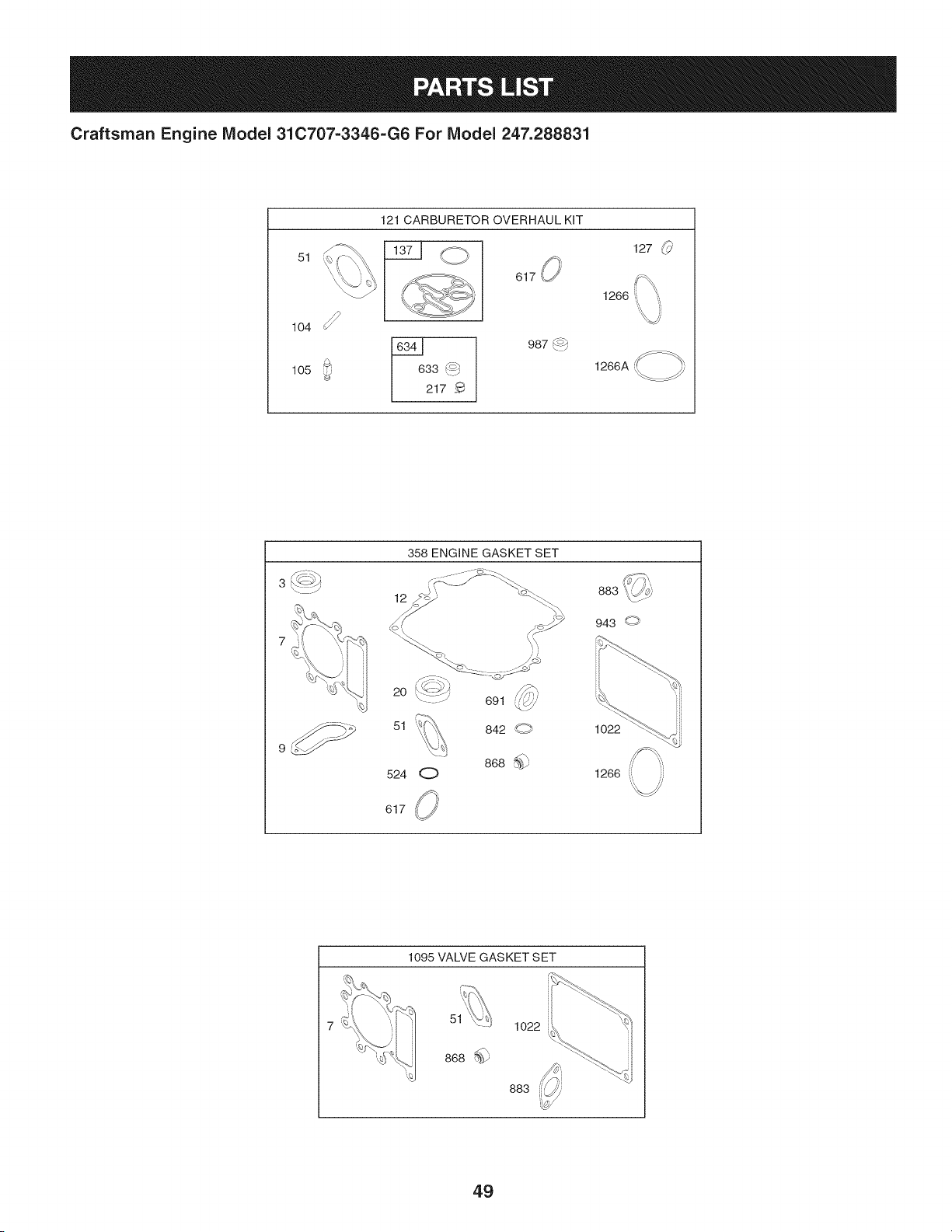
Craftsman Engine IViodel 31C707-3346-G6 For IViodel 247.288831
51
104
105
121 CARBURETOR OVERHAUL KiT
O 127 _
617,, ifX,
1266 :, '_,
33 _'_
217
987_/
1266A
/';/ .>_,
3 _<J/
358 ENGINE GASKET SET
12
_i /JJ
883
943 O
2O
51
524 O
691
842 g
868 %_9
1O22
1266 ((
617
1095 VALVE GASKET SET
51
868
1o22
883
49

Craftsman Engine IViodel 31C707=3346=G6 For IViodel 247.288831
Ref.
No,
1 796010
2 399265
3 391086s
4 697106
5 796026
7 796584
11 794683
12 697110
13 793988
15 690946
16 797579
20 795387
22 692125
23 698281
24 796335
25 796172
796173
26 791936
792649
27 698469
28 796007
29 794122
32 791118
33 792868
34 791935
35 691279
36 691279
37 697352
42 499586
43 691968
45 690564
46 793880
48 697761
50 796180
51 692137
51A 796081
53 690227
54 691148
78 691693
94 793610
95 690718
98 695408
Part No. Description
CylinderAssembly
Bushing/SealKit (MagnetoSide)
Seal-Oil (MagnetoSide)
Sump-Engine
Head-Cylinder
Gasket-CylinderHead
Tube-Breather
Gasket-Crankcase
Screw (Cylinder Head)
Plug-OilDrain
Crankshaft
Seal-Oil (PTOSide)
Screw(CrankcaseCover/Sump)
Flywheel
Key-Flywheel(Steel)
PistonAssembly(Standard)
PistonAssembly(.020"Oversize)
RingSet (Standard)
RingSet (.020" Oversize)
Lock-PistonPin
Pin-Piston
Rod-Connecting
Screw(ConnectingRod)
Valve-Exhaust
Valve-Intake
Spring-Valve(Intake)
Spring-Valve(Exhaust)
Guard-Flywheel
Keeper-Valve
Slinger-Governor/Oil
Tappet-Valve
Gear-Cam
Short Block
Manifold-Intake
Gasket-Intake
Gasket-Intake
Stud (Carburetor)
Screw(IntakeManifold)
Screw(FlywheelGuard)
KiNdle Mixture
Screw(ThrottleValve)
KiNdle Speed
50
I
Ref. I Part No,
No, I
104 694918
105 696136
108 695419
117 843099
118 790890
121 796184
125 796109
127 690727
130 699500
131 699501
133 694914
135 698780
137 698781
141 792777
146 691639
186 794873
187 791805
188 691693
192 691986
202 691841
209 692208
216 691840
217 695409
222 694042
227 691374
232 691842
238 691843
240 394358s
265 691024
267 794904
276 695410
304 797900
305 697102
305A 793376
305B 795891
306 796006
307 691693
309 693551
Description
Pin-FloatHinge
Valve-FloatNeedle
Valve-Choke
Jet-Main(Standard)
Jet-Main(HighAltitude)
Kit-CarburetorOverhaul
Carburetor
Plug-Welch
Valve-Throttle
Kit-ThrottleShaft
Float-Carburetor
Tube-FuelTransfer
Gasket-FloatBowl
Kit-ChokeShaft
Key-Timing
Connector-Hose(intake Manifold)
Line-Fuel(Formed)(Cutto RequiredLength)
Screw(ControlBracket)
Adjuster-RockerArm
Link-MechanicalGovernor
Spring-Governor(Green)
Link-Choke
Spring-ChokeReturn
Bracket-Control
Lever-GovernorControl
Spring-GovernorLink
Cap-Valve
Filter-Fuel
Clamp-Casing
Screw(CasingClamp)
Washer-Sealing
BlowerHousing
Screw (BlowerHousing) (1/4-20x1.14)
Screw (BlowerHousing) (1/4-20x.68)
Screw (BlowerHousing) (10-16x.43)
Shield-Cylinder
Screw(CylinderShield)
Motor-Starter
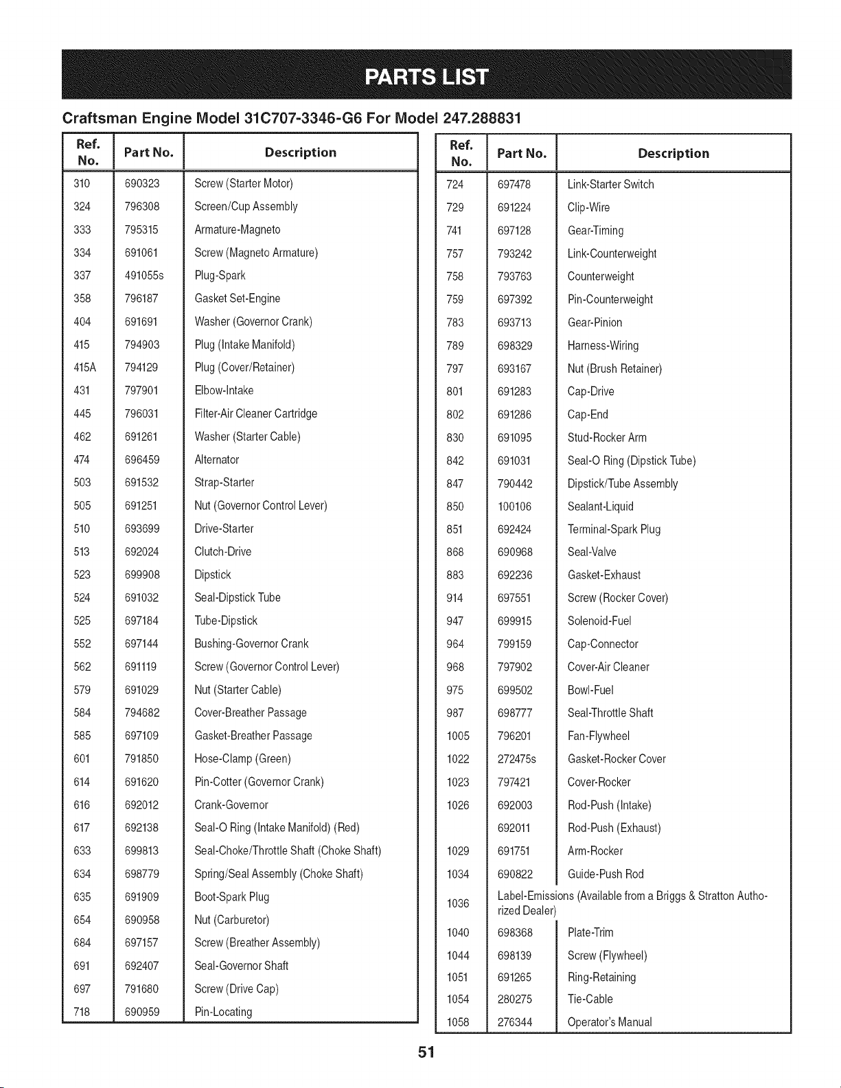
Craftsman Engine IViodel 31C707=3346=G6 For IViodel
I
Ref. I Part No.
No, I
310 690323
324 796308
333 795315
334 691061
337 491055s
358 796187
404 691691
415 794903
415A 794129
431 797901
445 796031
462 691261
474 696459
503 691532
505 691251
510 693699
513 692024
523 699908
524 691032
525 697184
552 697144
562 691119
579 691029
584 794682
585 697109
601 791850
614 691620
616 692012
617 692138
633 699813
634 698779
635 691909
654 690958
684 697157
691 692407
697 791680
718 690959
Description
Screw(Starter Motor)
Screen/CupAssembly
Armature-Magneto
Screw(MagnetoArmature)
Plug-Spark
GasketSet-Engine
Washer(GovernorCrank)
Plug(intake Manifold)
Plug(Cover/Retainer)
Elbow-intake
Filter-AirCleanerCartridge
Washer(StarterCable)
Alternator
Strap-Starter
Nut(GovernorControlLever)
Drive-Starter
Clutch-Drive
Dipstick
Seal-DipstickTube
Tube-Dipstick
Bushing-GovernorCrank
Screw(GovernorControlLever)
Nut(StarterCable)
Cover-BreatherPassage
Gasket-BreatherPassage
Hose-Clamp(Green)
Pin-Cotter(GovernorCrank)
Crank-Governor
SeaI-ORing (IntakeManifold)(Red)
Seal-Choke/ThrottleShaft (ChokeShaft)
Spring/SealAssembly(ChokeShaft)
Boot-SparkPlug
Nut(Carburetor)
Screw(BreatherAssembly)
Seal-GovernorShaft
Screw(DriveCap)
Pin-Locating
51
247.288831
Ref.
No,
724 697478
729 691224
741 697128
757 793242
758 793763
759 697392
783 693713
789 698329
797 693167
801 691283
802 691286
830 691095
842 691031
847 790442
850 100106
851 692424
868 690968
883 692236
914 697551
947 699915
964 799159
968 797902
975 699502
987 698777
1005 796201
1022 272475s
1023 797421
1026 692003
692011
1029 691751
1034 690822
1036
1040
1044
1051
1054
1058
Part No, Description
Link-StarterSwitch
Clip-Wire
Gear-Timing
Link-Counterweight
Counterweight
Pin-Counterweight
Gear-Pinion
Harness-Wiring
Nut (BrushRetainer)
Cap-Drive
Cap-End
Stud-RockerArm
SeaI-ORing(DipstickTube)
Dipstick/TubeAssembly
Sealant-Liquid
Terminal-SparkPlug
Seal-Valve
Gasket-Exhaust
Screw(RockerCover)
Solenoid-Fuel
Cap-Connector
Cover-AirCleaner
Bowl-Fuel
Seal-ThrottleShaft
Fan-Flywheel
Gasket-RockerCover
Cover-Rocker
Rod-Push(Intake)
Rod-Push(Exhaust)
Arm-Rocker
Guide-PushRod
Label-Emissions(Availablefrom a Briggs& StrattonAutho-
rized Dealer)
698368
698139
691265
280275
276344
Plate-Trim
Screw(Flywheel)
Ring-Retaining
Tie-Cable
Operator'sManual
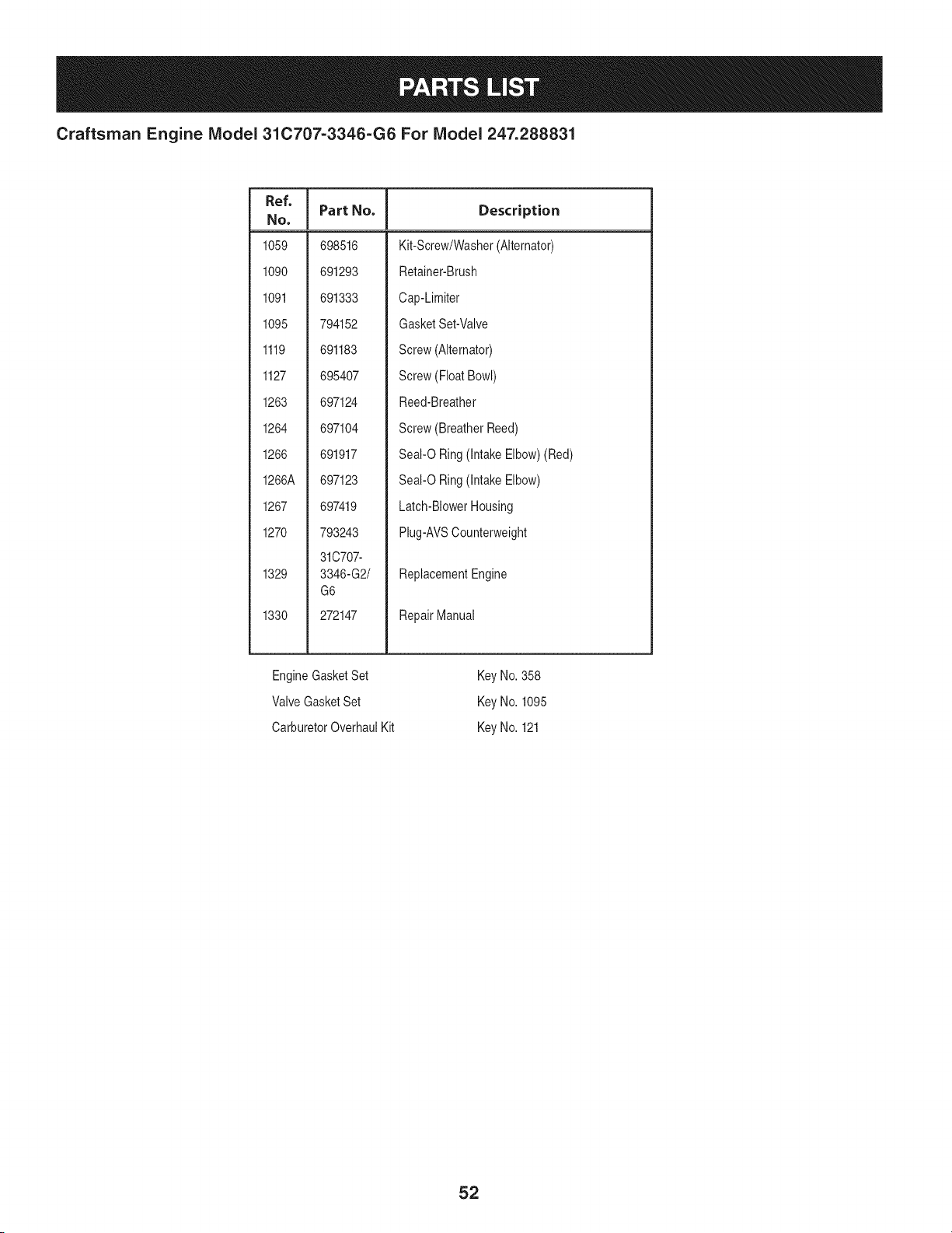
Craftsman Engine IViodel 31C707=3346=G6 For IViodel 247.288831
Ref, I
NO,
1059 698516
1090 691293
1091 691333
1095 794152
1119 691183
1127 695407
1263 697124
1264 697104
1266 691917
1266A 697123
1267 697419
1270 793243
31C707-
1329 3346-G2/
G6
1330 272147
Part No. Description
Kit-Screw/Washer(Alternator)
Retainer-Brush
Cap-Limiter
GasketSet-Valve
Screw(Alternator)
Screw(FloatBowl)
Reed-Breather
Screw(BreatherReed)
Seal-O Ring (IntakeElbow)(Red)
Seal-O Ring (IntakeElbow)
Latch-BlowerHousing
Plug-AVSCounterweight
ReplacementEngine
RepairManual
EngineGasketSet
Valve GasketSet
CarburetorOverhaulKit
KeyNo. 358
KeyNo. 1095
KeyNo. 121
52
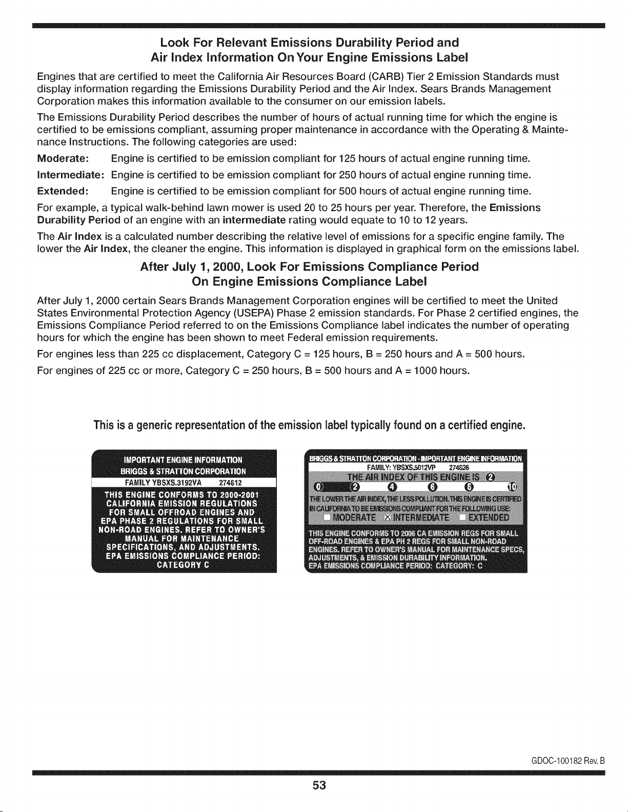
Look For Relevant Emissions Durability Period and
Air index information On Your Engine Emissions Label
Engines that are certified to meet the California Air Resources Board (CARB) Tier 2 Emission Standards must
display information regarding the Emissions Durability Period and the Air Index. Sears Brands Management
Corporation makes this information available to the consumer on our emission labels.
The Emissions Durability Period describes the number of hours of actual running time for which the engine is
certified to be emissions compliant, assuming proper maintenance in accordance with the Operating & Mainte-
nance Instructions. The following categories are used:
Moderate: Engine is certified to be emission compliant for 125 hours of actual engine running time.
Intermediate: Engine is certified to be emission compliant for 250 hours of actual engine running time.
Extended: Engine is certified to be emission compliant for 500 hours of actual engine running time.
For example, a typical walk-behind lawn mower is used 20 to 25 hours per year. Therefore, the Emissions
Durability Period of an engine with an intermediate rating would equate to 10 to 12 years.
The Air index is a calculated number describing the relative level of emissions for a specific engine family. The
lower the Air Index, the cleaner the engine. This information is displayed in graphical form on the emissions label.
After July 1,2000, Look For Emissions Compliance Period
On Engine Emissions Compliance Label
After July 1, 2000 certain Sears Brands Management Corporation engines will be certified to meet the United
States Environmental Protection Agency (USEPA) Phase 2 emission standards. For Phase 2 certified engines, the
Emissions Compliance Period referred to on the Emissions Compliance label indicates the number of operating
hours for which the engine has been shown to meet Federal emission requirements.
For engines less than 225 cc displacement, Category C = 125 hours, B = 250 hours and A = 500 hours.
For engines of 225 cc or more, Category C = 250 hours, B = 500 hours and A = 1000 hours.
This is ageneric representation of the emission label typically found on a certified engine.
FAMILYYBSXS.3192VA 274812
GDOC-100182Rev.B
53
(Thispageapplicablein the U.S.A.and Canadaonly.)
Sears Brands Management Corporation (Sears), the California Air Resources Board (CARD)
and the United States Environmental Protection Agency (U.S. EPA)
Emission Control System Warranty Statement (Owner's Defect Warranty Rights and Obligations)
EMISSIONCONTROLWARRANTYCOVERAGEISAPPLICABLETOCERTI-
FIED ENGINESPURCHASEDIN CALIFORNIAIN 1995ANDTHEREAF-
TER,WHICHARE USEDINCALIFORNIA,ANDTOCERTIFIEDMODEL
California and United States Emission
The CaliforniaAir ResourcesBoard(CARD),U.S.EPAand Searsare pleased
to explainthe EmissionControlSystemWarrantyon your modelyear2000and
latersmalloff-roadengine(SORE).InCalifornia,newsmall off-roadengines
mustbe designed,builtand equippedto meettheState'sstringentanti-smog
standards.Elsewherein the UnitedStates, newnon-road,spark-ignition
enginescertifiedfor modelyear 1997and latermustmeetsimilarstandardsset
forth bythe U.S.EPA.Sears mustwarrantthe emissioncontrol systemon your
YEAR 1997AND LATERENGINESWHICHARE PURCHASEDAND USED
ELSEWHEREIN THE UNITEDSTATES(ANDAFTERJANUARY1,2001 IN
CANADA).
Control Defects Warranty Statement
enginefor theperiodsoftime listedbelow,providedthere has been noabuse,
neglector impropermaintenanceof your smalloff-roadengine.Youremis-
sion controlsystem includespartssuch as thecarburetor,air cleaner,ignition
system,mufflerand catalyticconverter.Also includedmaybe connectorsand
otheremissionrelatedassemblies.Wherea warrantableconditionexists,Sears
will repairyour smalloff-roadengineat no costto you includingdiagnosis,parts
and labor.
Sears Emission Control Defects Warranty Coverage
Smalloff-roadenginesarewarrantedrelativeto emissioncontrol partsdefects
fora periodof one year,subjectto provisionsset forth below.Ifany covered
Owner's Warranty
Asthe smalloff-roadengine owner,you are responsiblefor the performanceof
therequiredmaintenancelistedin yourOperatingand MaintenanceInstruc-
tions.Searsrecommendsthatyou retain all yourreceiptscoveringmaintenance
on yoursmalloff-roadengine,but Sears cannotdenywarrantysolelyfor the
lackof receiptsorfor yourfailureto ensuretheperformanceof allscheduled
maintenance.As the smalloff-roadengineowner,you shouldhoweverbe
awarethat Searsmay deny you warrantycoverageif your smalloff-roadengine
ora part hasfailed dueto abuse,neglect,impropermaintenanceor unap-
parton yourengineis defective,the part willbe repairedorreplacedbySears.
Responsibilities
provedmodifications.Youare responsiblefor presentingyour smalloff-road
engineto an AuthorizedSearsServiceDealeras soonas a problemexists.The
undisputedwarrantyrepairsshouldbe completedin a reasonableamountof
time,not to exceed30 days. Ifyou haveany questionsregardingyourwarranty
rightsand responsibilities,you shouldcontacta SearsService Representative
at 1-800-469-4663.The emissionwarrantyis a defectswarranty.Defectsare
judged on normalengineperformance.The warrantyis notrelatedto an in-use
emissiontest.
Sears Emission Control Defects Warranty Provisions
ThefollowingarespecificprovisionsrelativetoyourEmissionControlDefectsWarrantyCoverage.ItisinadditiontotheSearsenginewarrantyfornon-regulated
enginesfoundin theOperatingand MaintenanceInstructions.
1. WarrantedParts
Coverageunderthis warrantyextendsonly to the parts listedbelow(the
emissioncontrolsystemsparts)to the extentthese partswere presenton
theengine purchased.
a. FuelMeteringSystem
•Cold start enrichmentsystem
•Carburetorand internalparts
•FuelPump
b. Air lnductionSystem
•Air cleaner
•Intakemanifold
c. IgnitionSystem
•Spark plug(s)
•Magnetoignitionsystem
d. CatalystSystem
•Catalyticconverter
•Exhaustmanifold
•Air injectionsystemor pulsevalve
e. MiscellaneousItemsUsedin AboveSystems
•Vacuum,temperature,position,timesensitivevalves
andswitches
• Connectorsandassemblies
2. Lengthof Coverage
Searswarrantsto the initialownerand eachsubsequentpurchaserthat
the WarrantedPartsshallbe free from defects in materialsand workman-
shipwhich causedthefailure of the WarrantedPartsfor a periodof one
yearfromthe datethe engineis deliveredto a retailpurchaser.
3. NoCharge
Repairor replacementof anyWarrantedPartwill be performedat no
chargeto the owner,includingdiagnosticlabor whichleadsto the
determinationthata WarrantedPartis defective,if the diagnosticwork is
performedat an AuthorizedSears ServiceDealer.For emissionswarranty
servicecontact yournearestAuthorizedSears ServiceDealeras listed in
the "YellowPages"under"Engines,Gasoline,""GasolineEngines,""Lawn
Mowers,"or similar category.
4. Claimsand CoverageExclusions
Warrantyclaimsshall be filed in accordancewiththe provisionsof the
Sears EngineWarrantyPolicy.Warrantycoverageshall be excludedfor
failuresof WarrantedPartswhichare notoriginal Sears partsor because
of abuse,neglector impropermaintenanceas setforth inthe Sears
EngineWarrantyPolicy.Sears is notliableto coverfailuresof Warranted
Partscausedby the use of add-on,non-original,or modifiedparts.
5. Maintenance
Any WarrantedPart whichis notscheduledfor replacementas required
maintenanceor whichis scheduledonly for regularinspectionto the effect
of "repairor replaceas necessary"shallbe warrantedas to defectsfor the
warrantyperiod.Any WarrantedPartwhich is scheduledfor replacement
as requiredmaintenanceshallbe warrantedas to defectsonly forthe
periodof time up to the first scheduledreplacementfor that part. Any
replacementpart that is equivalentin performanceand durabilitymay
be usedin the performanceof any maintenanceor repairs.The owneris
responsibleforthe performanceof all requiredmaintenance,as definedin
the SearsOperatingand MaintenanceInstructions.
6. ConsequentialCoverage
Coveragehereundershallextendto the failureof any enginecomponents
caused bythe failureof any WarrantedPartstill underwarranty.
Inthe USAandCanada,a 24 hour hotline, 1-800-469-4663,has a menu of pre-recordedmessagesofferingyou enginemaintenanceinformation.
GDOC-100188Rev.B
54
FEDERAL and/or CALIFORNIA EMISSION CONTROL WARRANTY STATEMENT
YOUR WARRANTY RIGHTS AND OBLIGATIONS
MTDConsumerGroupInc,the UnitedStatesEnvironmentalProtectionAgency (EPA),and, forthose productscertifiedfor sale in the stateof California,the
CaliforniaAir ResourcesBoard(CARB)are pleasedto explainthe emission(evaporativeand/or exhaust)controlsystem(ECS) warrantyon youroutdoor2006
andlater smalloff-roadspark-ignitedengine andequipment(outdoorequipmentengine)In California,new outdoorequipmentenginesmustbe designed,built and
equippedto meetthe State'sstringentanti-smogstandards (in otherstates, 1997andlater modelyear equipmentmustbe designed,built, and equippedto meet
the U.S. EPAsmalloff-road, sparkignitionengine regulations.MTDConsumerGroupInc mustwarrantthe ECSon your outdoorequipmentenginefor the period of
time listed belowprovidedtherehas been no abuse, neglector impropermaintenanceof outdoor equipmentengine.
Your ECSmay includeparts such as thecarburetor,fuel-injectionsystem,the ignitionsystem,catalyticconverter,fuel tanks,fuel lines,fuel caps, valves,canisters,
filters,vapor hoses,clamps,connectors,andotherassociatedemission-relatedcomponents.
Wherea warrantableconditionexists, MTDConsumerGroupIncwill repairyouroutdoor equipmentengine at no cost to you includingdiagnosis,parts and labor.
MANUFACTURER'S WARRANTY COVERAGE:
This emissioncontrolsystem is warrantedfor two years. If any emission-relatedpart on your outdoorequipmentengine is defective,the part will be repairedor
replacedby MTDCONSUMERGROUPINC.
OWNER'S WARRANTY RESPONSIBILITIES:
Asthe outdoorequipmentengineowner,you are responsiblefor performanceof the requiredmaintenancelisted inyour owner'smanual.MTDConsumerGroup
Inc recommendsthat you retain allreceiptscoveringmaintenanceon youroutdoor equipmentengine, butMTD ConsumerGroupInc cannotdeny warrantysolely
forthe lackof receipts.
Asthe outdoorequipmentengineowner,you shouldhoweverbe awarethat MTDConsumerGroupInc may denyyou warrantycoverageif your outdoorequipment
engineor a part has faileddue to abuse,neglect,or impropermaintenanceor unapprovedmodifications.
Youare responsiblefor presentingyouroutdoorequipmentengineto MTDConsumerGroupInc's distributioncenteror servicecenteras soon asthe problem
exists.The warrantyrepairsshouldbe completedin a reasonableamountof time, notto exceed30 days. If you havea questionregardingyour warrantycoverage,
you shouldcontactthe MTDConsumerGroupIncService Departmentat 1-800-800-7310or via emailat http://support.mtdproducts.com
GENERAL EMISSIONS WARRANTY COVERAGE:
MTDConsumerGroupIncwarrantsto the ultimatepurchaserand eachsubsequentpurchaserthat the outdoorequipmentengineis: Designed,built and equipped
so asto conformwithall applicableregulations;and freefromdefects in materialsand workmanshipthatcausethe failureof a warrantedpart to be identicalin all
materialrespectsto that part as describedin MTDConsumerGroup Inc'sapplicationfor certification.
The warrantyperiodbeginson thedate the outdoorequipmentengine is deliveredto an ultimatepurchaseror first placedinto service.The warrantyperiodis two
years.
Subjectto certain conditionsand exclusionsas stated below,the warrantyon emission-relatedparts is asfollows:
1. Any warrantedpart that is not scheduledfor replacementas requiredmaintenancein thewritten instructionssupplied, is warrantedforthe warrantyperiod
statedabove. Ifthe part fails duringthe periodof warrantycoverage,thepart will be repairedor replacedbyMTDConsumerGroupInc accordingto subsection
(4) below. Anysuch part repairedor replacedunderwarrantywill be warrantedfor the remainderof the period.
2. Any warrantedpart that is scheduledonly for regularinspectionin the writteninstructionssupplied is warrantedforthe warrantyperiodstatedabove.Any such
part repairedor replacedunderwarrantywill be warrantedforthe remainingwarrantyperiod.
3. Any warrantedpart that is scheduledfor replacementas requiredmaintenancein thewritten instructionssuppliedis warrantedfor the period of timebeforethe
first scheduledreplacementdatefor that part. If the partfails beforethefirst scheduledreplacement,the part will be repairedorreplacedby MTDConsumer
GroupInc accordingto subsection(4) below.Any such part repairedor replacedunderwarrantywill be warrantedfor the remainderof the period priorto the
first scheduledreplacementpointfor the part.
4. Repairor replacementof any warrantedpart underthe warrantyprovisionshereinmust be performedat a warrantystationat no chargeto the owner.
5. Notwithstandingthe provisionsherein,warrantyservicesor repairswill be providedat allof our distributioncentersthatare franchisedto servicethe subject
enginesor equipment.
6. The outdoorequipmentengineownerwill notbe chargedfor diagnostic laborthat is directlyassociatedwithdiagnosisof a defective,emission-relatedwar-
rantedpart, providedthat suchdiagnosticwork is performedat a warrantystation.
7. MTDConsumerGroupInc is liablefor damagesto otherengine or equipmentcomponentsproximatelycausedby a failure underwarrantyof any warranted
part.
8. Throughoutthe off-roadengineand equipmentwarrantyperiodstatedabove,MTDConsumerGroup Inc will maintaina supply of warrantedparts sufficientto
meetthe expecteddemandfor such parts.
9. Any replacementpart may be usedin the performanceof any warrantymaintenanceor repairsand mustbe providedwithoutchargeto the owner.Such use will
notreducethe warrantyobligationsof MTDConsumerGroup Inc.
10. Add-onor modified partsthat are notexemptedbythe Air ResourcesBoardmay not be used.The use of any non-exemptedadd-on or modifiedparts by the
ultimatepurchaserwill be groundsfor disallowinga warrantyclaims. MTDConsumerGroup Incwill not beliable to warrantfailuresof warrantedparts caused
bythe use of a non-exemptedadd-onor modifiedpart.
WARRANTED PARTS:
The repairor replacementof any warrantedpart otherwiseeligiblefor warrantycoveragemaybe excludedfrom such warrantycoverageif MTDConsumerGroup
Inc demonstratesthatthe outdoorequipmentenginehas beenabused,neglected,orimproperlymaintained,and that suchabuse, neglect,or impropermainte-
nancewas the direct causeof the needfor repairor replacementof the part. That notwithstanding,any adjustmentof a componentthat hasa factory installed,
andproperlyoperating,adjustmentlimitingdevice is still eligible for warrantycoverage.Further,the coverageunderthis warrantyextendsonly to partsthat were
presenton the off-roadengineand equipmentpurchased.
Thefollowing emissionwarrantypartsare covered(if applicable):
(1) FuelMeteringSystem
• Cold start enrichmentsystem(softchoke)
• Carburetorand internalparts (or fuel injectionsystem)
• Fuelpump
• Fueltank
(2) Air InductionSystem
• Air cleaner
• Intakemanifold
(3) IgnitionSystem
• Spark plug(s)
• Magnetoignitionsystem
(4) ExhaustSystem
• Catalyticconverter
• SAI (Reed valve)
(5) MiscellaneousItemsUsedin AboveSystem
• Vacuum,temperature,position,timesensitivevalvesand switches
• Connectorsandassemblies
(6) EvaporativeControl
• Fuelhose
• Fuelhoseclamps
• Tetheredfuel cap
• Carboncanister
• Vapor lines
GDOC-100223Rev.A

Congratulations on making a smart purchase. Your new Craftsman® product is designed and
manufactured for years of dependable operation. But like all products, it may require repair
from time to time. That's when having a Repair Protection Agreement can save you money and
aggravation.
Here's what the Repair Protection Agreement* includes:
[] Expert service by our 10,000 professional repair specialists
[] Unlimited service and no charge for parts and labor on all covered repairs
[] Product replacement up to $1500 if your covered product can't be fixed
[] Discount of 25% from regular price of service and related installed parts not covered by the
agreement; also, 25% off regular price of preventive maintenance check
[] Fast help by phone - we call it Rapid Resolution - phone support from a Sears representative.
Think of us as a "talking owner's manual."
Once you purchase the Repair Protection Agreement, a simple phone call is all that it takes for you
to schedule service. You can call anytime day or night, or schedule a service appointment online.
The Repair Protection Agreement is a risk-free purchase. If you cancel for any reason during the
product warranty period, we will provide a full refund. Or, a prorated refund anytime after the
product warranty period expires. Purchase your Repair Protection Agreement today!
Some limitations and exclusions apply. For prices and additional information in the U.S.A.
call 1=800=827=6655.
*Coverage in Canada varies on some items. For full details call Sears Canada at 1=800=361=
6665.
Sears Installation Service
For Sears professional installation of home appliances, garage door openers, water heaters, and
other major home items, in the U.S.A. or Canada call 1=800=4=MY=HOME®.
57
Operaci6n segura Pr,_cticas .......... Paginas 59
Asamblea ......................... Paginas 65
Operaci6n de ...................... Paginas 67
De Servicio y Mantenimiento de ....... Paginas 74
Fuera de temporada de almacenamiento Paginas 83
Soluci6n de problemas .............. Paginas 84
Lista de piezas ..................... Paginas 30
Reparaci6n de Acuerdo de Protecci6n .. Paginas 91
Servicio de nOmeros .......... atrasados Paginas
CRAFTSMAN GARANT|A TOTAL
PORDOSANOSapartirdelafechadecornpra,todaslaspartesnofungiblesdeesteequipode equitaci6nest&ngarantizadoscontracualquierdefectode
materialornanodeobra.Unapiezadefectuosanofungiblesrecibir_nreparaci6ngratuitaenel hogaro la sustituci6nsilareparaci6nesirnposible.
DURANTECINCOANOSdesdelafechadecornpra,elmarcodeesteequipodernontaracabaloest_garantizadocontracualquierdefectodernaterialeso
rnanodeobra.Uncuadrodefectuosorecibir_ngratuitarnenteenel hogarreparaci6nosustituci6nsi lareparaci6nes irnposible.
PORDIEZANOSdesdelafechadecornpra,elejedelanterodeesteequipodernontaracabaloest_garantzadocontracualquierdefectodernaterialeso
rnanodeobra.Unejedelanterodefectuosorecibir_ngratuitarnenteen el hogarreparaci6no sustituci6nsila reparaci6nesirnposible.
POR90DfASa partrdelafechade cornpra,labateria(unapartefungibles)deesteequipodeequitaci6nest_garantizadacontracualquierdefectode
materialornanodeobra(nuestraspruebasdernuestraquenornantienelacarga).UnabateriadefectuosarecibirAreernplazogratuitoenel hogar.
ADICIONALDEGARANTiALIMITADADEPORVIDAen FUNDICIONejedelantero(siest_instalado)
PARASlEMPREY CUANDOSEUTILIZAporelpropietariooriginalluegodeld_cirnoaSodesdelafechadecornpra,el hierrofundidoejedelantero(siest&
equipado)de esteequipoecuestreestAgarantizadocontracualquierdefectodernaterialeso rnanodeobra.Conelcornprobantede cornpra,unaplanchade
yesodefectuososejedelanterorecibirAgratisen la viviendade reernplazo.
GARANTiADESERVICIO
Paraobtenerinformaci6ndetaladacoberturade lagarantaparaobtenerlareparaci6no sustituci6ngratuita,Ilarneal 1-800-659-5917ovisiteelsitioweb:
www.craftsman.corn
Entodosloscasosanteriores,sila reparaci6noreemplazodeunaparteesimposible,el equipodeequitaci6nser&reemplazadodeformagratuitaconel
rnisrnooequivalente.
Todoslosdelacoberturadela garantiaanterioresinv&lidasiesteequipode rnontaracabaloesutlizadoalgunavez,rnientrasquelaprestaci6ndeservicios
cornercialeso si sealqulaa otrapersona.
Estagaranta cubrelosdefectosSOLOde materialesy fabricaci6n.Lagaranta noincluye:
• Laspartesconsurnibles(exceptolabaterh)quepuedegastarseporel usonormaldentrodelperiododegaranth,incluyendoperonolrnitadoa, cuchilas,
bujhs,fltrosdeaire,correasy fltrosdeaceite.
• Losserviciosdernantenirniento,carnbiosde aceite,opuestasapunto.
•Tireel reernplazoo reparaci6ndepinchazoscausadospotobjetosexternos,talescornoclavos,espinas,toconeso vidrio.
•Tiredela ruedaoelreernplazoolareparaci6nresulantesdeldesgastenormal,accidenteo rnalfuncionarnientoo rnantenirniento.
• Lasreparacionesnecesariasdebidoalabusodel operador,incluyendoperonolrnitadoa losdaios causadosporel rernolquedelosobjetosrn&sall&de la
capacidaddelequipodeequitaci6n,el irnpactodeobjetosquedoblenlaestructura,el rnontajedelejeo delcigieSal,odeexcesodevelocidaddelmotor.
• Lasreparacionesnecesariasdebidoalanegligenciadel operador,incluyendoperonolirnitadoa, daios el_ctricosy rnecanicoscausadospotunalrnace-
narnientoinadecuado,noutlizaci6ndelacaidadocantidaddeaceitedemotor,nornantenerel pisolbre de residuosinlarnables,o faltade rnantenirniento
delEquipoecuestredeacuerdoalas instruccionescontenidasenelmanualdeloperador.
• Elmotor(sisternade combustible)delrnpiezao reparacionesprovocadasporun combustiblequesecontarninadouoxidado(viejo).Engeneral,el
combustibledebeserutilzadodentrodelos30 dhs siguientesa lafechadecornpra.
• deterioroy desgastenormaldelosacabadosexteriores,o reernplazodelaetiquetadel producto.
Estagaranthleotorgaderechoslegalesespeclicos,y ustedtarnbi_npuedetenerotrosderechosquevarhnde estadoaestado.
SearsBrandsManagementCor
Aceitedel motor: SAE30
Combustible: Gasolna sinplorno
Bujia: Champion®RC12YC
Motor: Briggs& Stratton
_oration,HoffmanEstates,iL60179
NSrnerode rnodelo ..........................................................
N_mero de serie..............................................................
Fechade compra .............................................................
Registrearribaeln_merodelmodelo,eln_merodeserieylafechadecompra
© Sears Brands,LLC
58
Lapresenciade este sirnboloindicaque setrata de instrucciones
irnportantesde seguridadquese debenrespetarparaevitar
poneren peligrosu seguridadpersonaly/o materialy lade otras
personas.Leay siga todaslas instruccionesdeeste manualantes
de poneren funcionarnientoestarn_.quina.Si no respetaestas
instruccionespodriaprovocarlesionespersonales.Cuandoveaeste
sirnbolo,ipresteatenci6na la advertencia!
PROPOSICION 65 DE CALIFORNIA
Elescapedel motordeeste producto,algunosde suscornponentes
y algunoscornponentesdelvehiculocontieneno liberan sustancias
quirnicasqueel estado de Californiaconsideraque puedenproducir
c_.ncer,defectosde nacirnientouotros problernasreproductivos.
Losbornesdela bateriay los accesoriosalinescontienenplornoy
cornpuestosde plorno,sustanciasquirnicasque seg_nIo estableci-
do porel Estadode Californiacausanc_.ncery da_osenel sisterna
reproductivo.Ldveselas manos despu_sde estaren contacto
con estoscomponentes.
Estarn_.quinarueconstruidapara seroperadade acuerdocon
las reglasde seguridadcontenidasenestemanual.AI igualque
concualquiertipo deequipornotorizado,undescuidoo errorpor
partedeloperadorpuedeproducirlesionesgraves.Esta rn_.quina
es capazde arnputarrnanosy piesy de arrojarobjetoscon gran
fuerza.Deno respetarlas instruccionesde seguridadsiguientesse
puedenproducirlesionesgraveso la rnuerte.
Su responsabilidad--Restrinja el usode estarn_.quina
rnotorizadaalas personasque lean,cornprendany respetenlas
advertenciase instruccionesque aparecenen este manualyen la
rn_.quina.
iGUARDEESTASINSTRUCCIONES!
FUNCIONAMIENTO GENERAL
•Lea,entienday curnplatodaslas instruccionesincluidasen
la rn_.quinayen los rnanualesantes de rnontarlay utilizarla.
Guardeestemanualen un lugarseguroparaconsultasfuturasy
peri6dicas,asi cornoparasolicitarrepuestos.
•Farniliaricesecontodoslos controlesy con el usoadecuado
delos rnisrnos.Sepac6rnodetenerlarn_.quinay desactivarlos
controlesr_.pidarnente.
• No perrnitanuncaque los ni_osrnenoresde 14a_osutilicen
estarn_.quina.Los ni_osde 14a_osen adelantedebenleery
entenderlas instruccionesde operaci6ny norrnasde seguridad
contenidaseneste manual,yen la rn_.quinay debenser
entrenadosy supervisadospor unadulto.
• Nuncaperrnitaquelos adultosoperenestarn_.quinasin recibir
antesla instrucci6napropiada.
• Paraayudaraevitarel contactocon las cuchillaso unalesi6npor
algQnobjetoquesea arrojado,rnantengaa los observadores,a
los ayudantes,ni_osy rnascotasalejadosal rnenos25 metrosde
la rn_.quinarnientrasest,.en funcionarniento.Detengala rn_.quina
si alguienentraen la zona.
• Inspeccionerninuciosarnenteel Areadonde utilizar_,el equipo.
Retiretodaslas piedras,palos,cables,huesos,juguetesy otros
objetosextra_osquepodrianser recogidosy arrojadospor la
acci6nde las cuchillas.Losobjetosarrojadospor la rn_.quina
puedenproducirlesionesgraves.
• Planifiqueel patr6nde corte delc_spedque hade seguirpara
evitarla descargade materialhacialoscarninos,las veredas,los
observadores,etc.Eviteadern_.sdescargarmaterialcontralas
paredesy obstruccionesquepodrianprovocarqueel material
descargadorebotecontrael operador.
• Paraprotegerselos ojos utilicesiernpreanteojoso antiparras
deseguridadrnientrasopera la rn_.quinao rnientrasla ajusta
o repara.Losobjetosarrojadosque rebotanpuedenproducir
lesionesocularesgraves.
•Utilicezapatosde trabajoresistentes,desuelafuerte,asi corno
pantalonesy carnisasajustados.Las prendassueltaso las
alhajaspuedenquedaratrapadasen las piezasrnovibles.Nunca
operela rn_.quinadescalzoo con sandalias.
• Est_atentoa lacortadoray a la direcci6nde la descargade
losaditarnentosy noapuntea nadie.Nuncaopere la cortadora
de c_spedsin queest_nen su lugarapropiadola cubiertade
descargao elcolectorde recortesdecesped.
• Nopongalasrnanoso lospies cercade las piezasrotatoriaso
debajode la plataforrnade corte. El contactocon las cuchillas
puedeproducirla arnputaci6ndernanosy pies.
• Unacubiertade descargafaltanteo da_adapuedeprovocarel
contactocon lacuchillao lesionespot objetosarrojados.
• Detengala(s)cuchilla(s)cuandoatraviesesenderos,sendaso
carninosde gravay cuandono est_cortandoel cesped.
• Vigileel tr_.nsitovehicularcuandoest_operandocercade o en
crucesde carninos.Estarn_.quinanodebe utilizarseen lavia
pQblica.
• Noopereestarn_.quinabajo losefectosdel alcoholo de drogas.
• Corteel cespedsolarnentecon luzdediao conunabuenaluz
artificial.
• Nuncatransportepasajeros.
• Desenganchela(s)cuchilla(s)antesdecolocarlarnarchaatr_.s.
Retrocedalentarnente.Siernpremirehaciaabajoy haciaatr_.santes
y rnientrasretrocede,paraevitaraccidentes.
• Reduzcala velocidadantesde dar la vuelta.Operelarn_.quina
suavernente.Evitela operaci6nerr_.ticay la velocidadexcesiva.
• Desenganchela(s)cuchilla(s),coloqueelfrenode estaciona-
rniento,detengaelmotory esperehastaque la(s)cuchilla(s)se
detenga(n)porcornpletoantesderetirarel colectorde c_sped,
vaciarlos recortes,destaparel canal,retirarrestosde cespedo
desechos,o hacercualquierajuste.
59
• Nuncadejelarn_.quinaen funcionarnientosinvigilancia.Apague
siernprelascuchillas,coloqueelfrenode rnano,detengaelmotory
retirela Ilaveantesdebajarsedelvehiculo.
• Tengasurnocuidadoal cargaro descargarlarn_.quinaen un
rernolqueocarni6n.Estaunidadnodebeconducirseenascensoo
descensoderarnpas,porquepodrialadearsey provocarlesiones
personalesgraves.Enlas rarnpasla rn_.quinasedebeernpujar
rnanualrnenteparacargarlao descargarlacorrectarnente.
• Elsilenciadory el motorse calientany puedencausarquernaduras.
Nolos toque.
• Reviseel espaciolibrepot encirnade la cabezaantesde conducir
bajolas rarnasbajasde_.rboles,cables,cerrarnientosde puertas,
etc.enloscualeseloperadorpodriaatorarseo serernpujadofuera
dela rn_.quina,Ioque podriaresultaren lesionesgraves.
• Desenganchetodoslosernbraguesdelos accesoriosy presione
totalrnenteel pedaldelfrenoantesde intentararrancarel motor.
• Larn_.quinaest,.diseSadaparacortarc_spedresidencialnormal,
conunaalturanomayora 10".Nointentecortarcespeddernasiado
crecido,seco(porej.,pastura)nipilasdehojassecas.Elc_sped
y las hojassecaspuedenentraren contactoconel escapedel
motory/o acurnularseenla plataforrnade la cortadorade cesped,
convirti_ndoseen un peligrode incendio
• Utilicesolarnenteaccesoriosy aditarnentosaprobadosparaesta
rn_.quinapot el fabricantede la rnisrna.Lea,cornprenday siga
todaslasinstruccionesproporcionadasconlosaccesorioso
aditarnentosaprobados.Paraobteneruna listade losaccesorios
aprobadosy losarchivosadjuntos,Ilarne1-800-659-5917.
• Losdatosestadsticosrnuestranquelosoperadoresde60 aSos
y rnayoresseven involucradosen un altoporcentajedelesiones
relacionadascontractorescortacesped.Estosoperadoresdeben
evaluarsu capacidadparaoperarel tractorcortac_speden forrna
suficienternentesegurapara protegersea ellosrnisrnosy alos
dern_.scontralesionesgraves.
Si se presentansituacionesqueno est_.nprevistasen este
manualsea cuidadosoy use el sentidocornQn.Contacto1-800-
659-5917parainforrnaci6ny asistencia.
FUNCIONAiVIIENTO EN PENDIENTES
Las pendientesson unfactorirnportanterelacionadoconaccidentes
porderrapey vuelcosquepuedenproducirlesionesgravese incluso
la rnuerte.Laoperaci6nen pendientesrequieremayorprecauci6n.
Si nopuederetrocederen la pendienteo si no se sienteseguro,no
realiceningunaoperaci6ndecorte.
Parasu seguridad,use el indicadorde pendientesque se incluye
cornopartede estemanualpararnedirla pendienteantesde operarla
rn_.quinaenunazonainclinada.Sila pendientees mayorde 15grados
segQnel rnedidor,no opereesta rn_.quinaen ese sector,puespodria
causarlesionesgraves.
HagaIo siguiente:
•Podehaciaarribay abajodelas pendientes,nodeforrnatrans-
versal.Tengacuidadocuandocarnbiededirecci6nal operaren
pendiente.
• Est_atentoa loshoyos,surcos,baches,rocas,uotrosobjetos
ocultos.Elterrenodesniveladopuedevoltearla rn_.quina.El cesped
altopuedeocultarobst_.culos.
Vayaa bajavelocidad.ElijaunavelocidadIosuficienternentebaja,
de rnodoqueno tengaque detenerseohacercarnbiosrnientras
est,.sobrela pendiente.Losneurn_.ticospodrianperdertracci6n
sobrelaspendientesaQncuandolosfrenosfuncionaranapro-
piadarnente.Siernprernantengalarn_.quinaen carnbiornientras
desciendelaspendientes,parapoderfrenarconel motor.
• Sigalas recornendacionesdelfabricanteparalos pesoso contra-
pesosdelas ruedas,pararnejorarla estabilidadde la rn_.quina.
Pararecornendaciones,Ilarneal 1-800-659-5917.
• Tengaespecialcuidadocon loscolectoresdecespeduotros
aditarnentos.Losrnisrnospuedenrnodificarlaestabilidaddela
rn_.quina.
• Hagaquetodoslos rnovirnientosen laspendientesseanlentosy
graduales.Nocarnbierepentinarnentelavelocidadnila direcci6n.
Unfrenadoo carnbiodevelocidadrepentinospuedencausarque
el frentede la rn_.quinase levantey d_unavolteretahaciaatr_.s,Io
quepodriaproducirlesionesgraves.
• Evitearrancaro detenerseenuna pendiente.Silosneurn_.ticos
pierdenlatracci6n,desenganchelascuchillasy descienda
lentarnentela pendiente.
No hagaIo siguiente:
•Nogiresobrelas pendientesa rnenosqueseanecesario.Sies
posible,girelentarnentey gradualrnenteduranteeldescenso.
• Nocorteelc_spedcercade pozos,hundirnientoso terraplenes.La
cortadoradec_spedpuedevolcarserepentinarnentesiunade las
ruedasest,.sobreelhordede unacantilado,zanjao siunhordese
desrnorona.
• Nointenteestabilizarlarn_.quinaponiendoelpie enel suelo.
• Noutiliceuncolectordecespeden pendientesernpinadas.
• Nopodeelcespedh_rnedo.Unarnenortracci6npodriacausar
derrapes.
• Noparadescender.Elexcesodevelocidadpuedehacerqueel
operadorpierdael controldela rn_.quina,ocasionandolesiones
graveseinclusola rnuerte.
• Norernolquecargaspesadasdetr_.sdelosaditarnentos(carritode
basuracargado,podadoraderodillos,etc)en pendientesrnayores
de5 grados.Cuandosedesplazapendienteabajo,el pesoadicional
tiendeaernpujarel tractory puedehacerquese pierdaelcontrol
delrnisrno(porejernplo,eltractorsepuedeacelerar,se reducela
capacidadparafrenary rnaniobrar,losaccesoriospuedenplegarse
cornouncortaplurnasy hacerqueeltractorvuelque).
NINOS
Puedenocurriraccidentestr_.gicossi el operadornoest,.atentoa la
presenciade niSos.PotIo general,los niSosse sientenatraidospor
estetipo de rn_.quinasy su funcionarniento.Noentiendenlos riesgos
ni los peligros.Nuncaasurnaquelos niSosperrnanecer_.nen el rnisrno
lugardonde losvio pot Qltirnavez.
• Mantengaa losniSosfueradel_.readetrabajoy bajoestricta
vigilanciadeunadultoresponsableadern_.sdelpropiooperador.
Est_alertay apaguela rn_.quinasiunniSoingresaal_.rea.
• Antesy rnientrasest,.retrocediendo,mirehaciaatr_.sy cuidequeno
hayaniSos.
NuncatransporteniSos,aQnconlacuchillaapagada.Podriancaerse
y resultarseverarnenteheridoso interferirconlaoperaci6nsegurade
la rn_.quina.
Tengaextrernaprecauci6ncuandoseaproxirnea esquinasciegas,
portales,arbustos,_.rbolesu otrosobjetosquepuedanirnpedirlever
a unniSoquesecruceenel recorridode larn_.quina.
6O
• Paraevitaraccidentesal operaren rnarchaatr_.s,siernpredesengan-
chelascuchillasantesde colocarrnarchaatr_.s.Siest,. instalado,
el"ModoPrecaucidnMarchaAtr_.s"(hojasde operarla rn_.quina,
rnientrasquelospaseosala inversa)nodebeutilizarsecuandohay
ni_osuotraspersonaspresentes.
• Mantengaa losni_osalejadosde losrnotoresen rnarchao calientes.
Puedensufrirquernadurasconunsilenciadorcaliente.
• RetirelaIlavecuandodejela rn_.quinasinvigilancia,evitequeuna
personasinautorizaci6nlarnaneje.
No perrnitanuncaque los ni_osrnenoresde 14a_osutilicenesta
rn_.quina.Losni_osde 14a_osen adelantedebenleery entenderlas
instruccionesdeoperaci6ny norrnasde seguridadcontenidaseneste
manual,yen la rn_.quinay deben serentrenadosy supervisadospor
unadulto.
REIVIOLQUE
• Rernolque_nicarnenteconunarn_.quinaquecuenteconun
enganchediseSadopararernolcar.Noacopleequiporernolcado
exceptoenelpuntodeenganche.
• Sigalasrecornendacionesdel fabricanteen Ioque respectaalos
lirnitesdepesode losequiposa rernolcary al rernolqueenpendien-
tes.Pararecornendaciones,Ilarneal 1-800-659-5917.
• Nuncaperrnitala presenciade niSosuotraspersonasdentroo sobre
losequiposrernolcados.
• Enlaspendientes,el pesodel equiporernolcadopuedecausar
p_rdidadetraccidny perdidadecontrolde larn_.quina.
• Siernpreuseextralaprecauci6nrernolcandoconunarn_.quina
capazdehacervueltasapretadas(p.ejpaseo"devueltacero"-enel
cortacesped).Hagaarnpliasvueltasparaevitaral gato-knifing.
• Despl_.ceselentarnentey dejedistanciaadicionalparafrenado.
• Noparadescender.
SERVIClO
Manejo seguro de la gasolina
Paraevitarlesionespersonaleso daSosrnaterialessea surnarnente
cuidadosoal rnanipularla gasolina.Lagasolinaes surnarnente
infiarnabley susvaporespuedencausarexplosiones.Se puede
lesionargravernentesi derrarnagasolinasobreustedo sobrela ropa,
ya que_sta se puedeincendiar. L_.vesela piely c_.rnbiesede ropade
inrnediato.
• Utilices61olos recipientesparagasolinaautorizados.
• NuncaIlenelos recipientesen el interiorde unvehiculoo carnidn
o cajade rernolquecon recubrirnientopl_.stico.Coloquesiernpre
los recipientesenel piso y lejosdel vehiculoantesde realizarla
carga.
• Cuandoseafactible,retireel equipoa gasolinadel carni6no
rernolquey II_neloen el suelo. Si esto no es posible,Ileneel
equipoen unrernolqueconun contenedorport_.til,en vez de
hacerlocon unaboquilladispensadorade gasolina.
• Mantengala boquillade Ilenadoencontactoconel hordedel
dep6sitode combustibleo con la aberturadel recipienteen todo
rnornento,hastaterrninarlacarga. No utiliceun dispositivode
boquilladeapertura/cierre.
• Apaguetodosloscigarrillos,cigarros,pipasy otrasfuentesde
cornbustidn.
• Nuncacarguecombustibleenla rn_.quinaenun espaciocerrado.
• Nuncasaquela tapadel combustibleniagreguecombustible
rnientrasel motorest,.calienteo en rnarcha.Dejequeel motor
seenfrie porIornenosdos rninutosantesde volvera cargar
combustible.
• NuncaIleneen excesoel dep6sitode combustible.Lleneel
tanquenorn_.sde 1/2pulgadapor debajode la basedel cuello
del tap6ndecarga,paradejar espaciopara la expansi6ndel
combustible.
• Vuelvaa colocarlatapa dela gasolinay ajQstelabien.
• Lirnpieel combustiblequese hayaderrarnadosobreel motory el
equipo.Trasladelarn_.quinaa otrazona.Espere5 rninutosantes
de encenderelmotor.
• Parareducirel riesgode incendio,rnantengala rn_.quinalirnpia
de pasto,hojasy de acurnulacidndeotros residuos.Lirnpielos
derrarnesdeaceiteo combustibley saquetodos los residuos
ernbebidosde combustible.
• Nuncaguardelarn_.quinao el recipientedecombustibleen un
espaciocerradodondehayafuego,chispaso luz piloto,corno
porejernplodecalentadoresdeagua,calefactoresde arnbientes,
hornos,secadoresde ropau otrosaparatosa gas.
• Dejequelarn_.quinase enfriecincorninutospor Iornenosantes
de guardarla.
Servicio general
•Nuncaenciendael motoren espacioscerradosoen una zona
con pocaventilacidn.Elescapedel motorcontienernondxidode
carbono,ungas inodoroy letal.
• Antesdelirnpiar,repararo inspeccionarla rn_.quina,cornpruebe
que la(s)cuchilla(s)y todaslas partesenrnovirnientose hayan
detenido.Desconecteel cablede la bujfay p6ngalohaciendo
rnasacontrael motorpara evitarque se enciendaaccidental-
rnente.
• Reviseperi6dicarnenteparaasegurarsequelas cuchillasse
detenganporcornpletoen aproxirnadarnentecinco(5) segundos
despu_sdeaccionarel controlde desenganchede la(s)
cuchilla(s).Si las cuchillasnose detienendentrodeeste lapso
de tiernpo,su unidaddeber_,ser reparadaporsu distribuidorde
servicioautorizadoMTD.
• Reviseconfrecuenciaelfuncionarnientodel sisternade frenos
ya queest,. sujetoa desgastepor la operaci6nnormal.Ajuste y
efectQernantenirnientosegQnse requiera.
61
• Reviselos pernosdemontajedela(s) cuchilla(s)y del motora
intervalosfrecuentesparaverificarqueest_nbienapretados.
Adem_.s,inspeccionevisualmentela(s) cuchilla(s)en buscade
daSos(porejemplo,desgasteexcesivo,abolladuras,rajaduras,
etc.). Reemplacela(s) cuchilla(s)Qnicamentecon lascuchillas
defabricantesde equiposoriginales(O.E.M.)listadasen este
manual.Elusode piezasque no cumplencon las especifi-
cacionesdelequipooriginal podriatenercomo resultadoun
rendimientoincorrectoy adem_.sponeren riesgola seguridad.
• Lascuchillasdelas podadorassonmuyafiladas.Envuelvala
cuchillao utiliceguantesy extremelasprecaucionescuando
efectQemantenimiento.
Mantengatodoslos pernos,tuercasy tornillosbienajustados
paraasegurarsede que la m_.quinase encuentraen condiciones
segurasde operaci6n.
• Nuncaaltereel sistemade enclavamientode seguridadni
otrosmecanismosde seguridad.Controleperiddicamenteque
funcionencorrectamente.
Despu_sdegolpearcon algQnobjetoextraSo,detengael motor,
desconecteel cablede la bujfay conecteel motora masa.
Inspeccioneminuciosamentela m_.quinaparaver si est,.daSada.
Repareel daSoantesde arrancary ufilizarla m_.quina.
Nuncatratede hacerajusteso reparacionesa la m&quina
mientrasel motorest&enmarcha.
• Loscomponentesdel colectordec_spedy la cubiertade
descarga,estansujetosa desgastey daSosque podriandejar
expuestaspartesen movimientoo permitirque se arrojenobjetos.
Paraprotegersuseguridad,verifiquefrecuentementetodoslos
componentesy reempl_.celosinmediatamentes61ocon piezasde
los fabricantesdel equipooriginal,listadosen este manual.Eluso
de piezasque no cumplencon las especificacionesdel equipo
originalpodriatenercomoresultadoun rendimientoincorrectoy
adem_.sponeren riesgola seguridad.
• Nocambielaconfiguraci6ndel reguladordel motorni Ioopere
a sobrevelocidad.El reguladordel motorcontrolala velocidad
m_.ximaseguradefuncionamientodel motor.
• Mantengao reemplacelasefiquetasde seguridade instrucciones
segQnseanecesario.
Respetelas normasreferentesa la disposicidncorrectay las
reglamentacionessobregasolina,aceite,etc. paraprotegerel
medicambiente.
• SegQnla Comisi6ndeSeguridadde Productosparael Consumi-
dorde los EstadosUnidos(CPSC)y laAgenciade Protecci6n
Ambientalde los EstadosUnidos(EPA),este productotieneuna
vida Qtilmediade siete(7)aSos,6 270horasdefuncionamiento.
AIfinalizarla vidaQtilmedia,adquieraunam_.quinanuevao haga
inspeccionaranualmente_staSearspor uno u otrodistribuidorde
serviciosparacerciorarsedeque todos los sistemasmec_.nicos
y de seguridadfuncionancorrectamentey no tienenexcesivo
desgaste.Si no Io hace,puedenproducirseaccidentes,lesiones
o muerte.
NO MODIFIQUE EL MOTOR
Paraevitarlesionesgraveso lamuerte,no modifiqueel motorbajo
ningunacircunstancia.Si cambialaconfiguraci6ndel reguladordel
motorel motorpuededescontrolarsey operara velocidadesinsegu-
ras.Nuncacambiela configuraci6ndef_.bricadel reguladordel motor.
AVlSO REFERIDO A EMISlONES
LosmotoresqueestAncertificadosy cumplencon las regulaciones
de emisionesfederalesEPAy de CaliforniaparaSORE(Equipos
pequeSostodoterreno)estAncertificadosparaoperarcongasolina
comQnsin plomoy puedenincluirlos siguientessistemasde control
de emisiones:Modificacidnde motor(EM) y catalizadorde tres vias
(TWC) siest_.nequipadosde esa manera.
GUARDACHISPAS
Estam&quinaest,.equipadacon unmotorde combusti6ninternay
nodebe ser ufilizadaen o cercade unterrenoagrestecubiertopor
bosque,malezaso hierbaexceptosi el sistemade escapedelmotor
est&equipadocon un amortiguadorde chispasque cumplacon las
leyeslocaleso estatalescorrespondientes,en caso de haberlas.
Si se utilizaunamortiguadorde chispasel operadorIo debemantener
en condicionesde usoadecuadas.Enel Estadode Californialas
medidasanteriormentemencionadassonexigidasporIcy (Arficulo
4442del C6digode RecursosPOblicosde California).Esposible
queexistanleyessimilaresenotros estados.Lasleyesfederalesse
aplicanenterritoriosfederales.
Puedeconseguirelamortiguadorde chispasparael silenciadora
travesdesu distribuidorautorizadode motoreso poni_ndoseen
contactoconel centrode servicioSears.
62
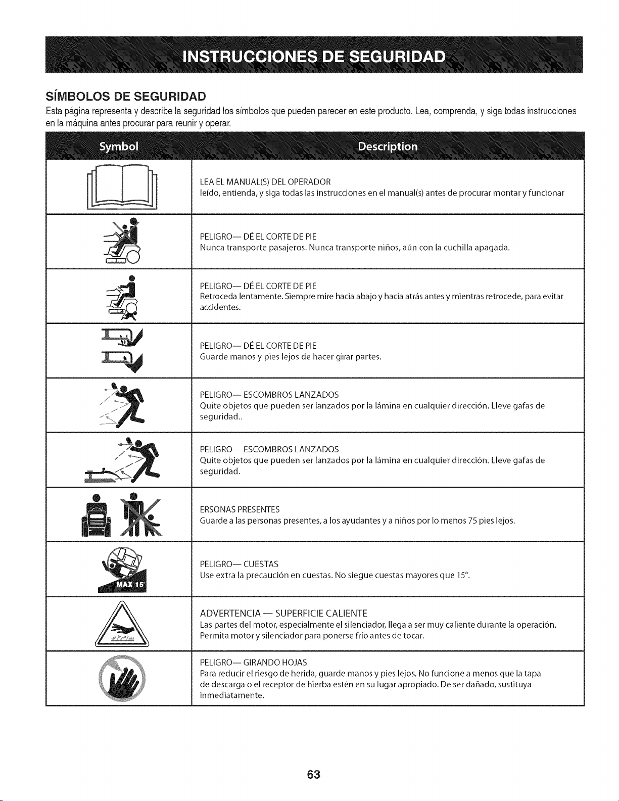
SilVlBOLOS DE SEGURIDAD
Estap&ginarepresentay describela seguridadlos simbolosque puedenpareceren este producto.Lea,comprenda,y sigatodas instrucciones
enla m_quinaantesprocurarpara reuniry operar.
0
J
AL
LEA EL MANUAL(S) DEL OPERADOR
leido, entienda, y siga todas las instrucciones en el manual(s) antes de procurar montar y funcionar
PELIGRO-- DE EL CORTE DE PIE
Nunca transporte pasajeros. Nunca transporte niffos, aun con la cuchilla apagada.
PELIGRO-- DIe EL CORTE DE PIE
Retroceda lentamente. Siempre mire hacia abajo y hacia atr_is antes y mientras retrocede, para evitar
accidentes.
PELIGRO-- DIe EL CORTE DE PIE
Guarde manos y pies lejos de hacer girar partes.
PELIGRO-- ESCOMBROS LANZADOS
Quite objetos que pueden set lanzados por la I_imina en cualquier direcci6n. Lleve gafas de
seguridad..
PELIGRO-- ESCOMBROS LANZADOS
Quite objetos que pueden set lanzados por la I_imina en cualquier direcci6n. Lleve gafas de
seguridad.
ERSONAS PRESENTES
Guarde alas personas presentes, a los ayudantes y a ni_os por Io menos 75 pies lejos.
PELIGRO-- CU ESTAS
Use extra la precauci6n en cuestas. No siegue cuestas mayores que 15°.
ADVERTENCIA-- SUPERFICIECALIENTE
Las partes del motor, especialmente el silenciador, Ilega a set muy caliente durante la operaci6n.
Permita motor y silenciador para ponerse frio antes de tocar.
PELIGRO-- GIRANDO HOJAS
Para reducir el riesgo de herida, guarde manos y pies lejos. No funcione a menos que la tapa
de descarga o el receptor de hierba est_n en su lugar apropiado. De set dahado, sustituya
inmediatamente.
63
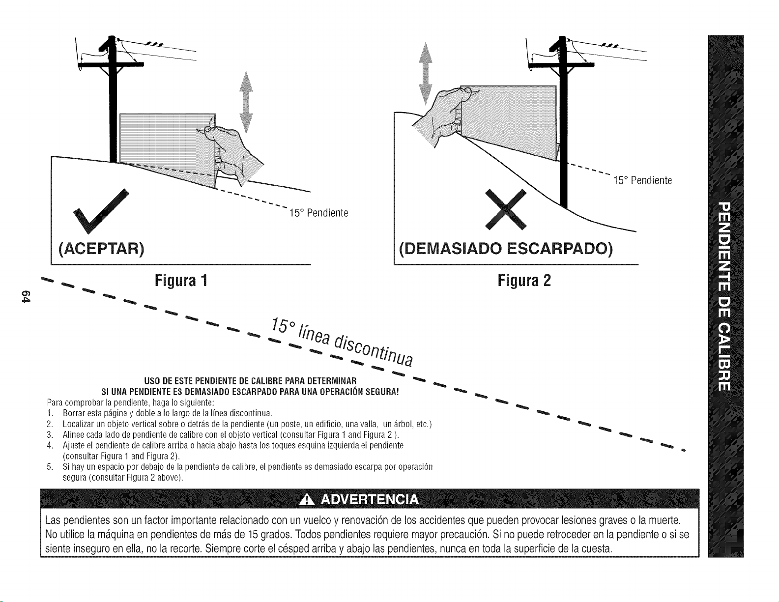
(ACEPTAR)
I5 ° Pendiente X
(DEMASIADO ESCARPADO)
15° Pendiente
4_
•Figura1
"'"
USO DE ESTE PENDiENTE DE CALIBRE PARA DETERrvIINAR
SlUNA PENDIENTE ES DEIVlASIADOESCARPADO PARA UNA OPEBACION SEGURA!
Para comprobar la pendiente, haga Io siguiente:
1. Borrar esta p_ginay doble a Io largo de la linea discontinua.
2.
3.
4.
5,
Localizar un objeto vertical sobre o detr_.sde la pendiente (un poste, un edificio, una valla, un _.rbol,etc.)
Alinee cada lado de pendiente de calibre con el objeto vertical (consultar Figura 1 and Figura 2 ).
Ajuste el pendiente de calibre arriba o hacia abajo hasta los toques esquina izquierda el pendiente
(consultar Figura 1 and Figura 2).
Si hay un espacio por debajo de la pendiente de calibre, el pendiente es demasiado escarpa por operaci6n
segura (consultar Figura 2 above).
Figura 2
Las pendientesson un factor importante relacionado con un vuelco y renovaci6nde los accidentes que pueden provocar lesiones graves o la muerte.
No utilice la ma.quinaen pendientes de ma.sde 15 grados. Todos pendientes requiere mayor precauci6n. Si no puede retroceder en la pendienteo si se
siente inseguro en ella, no la recorte. Siemprecorte el cesped arriba y abajo las pendientes, nunca en toda la superficie de la cuesta.
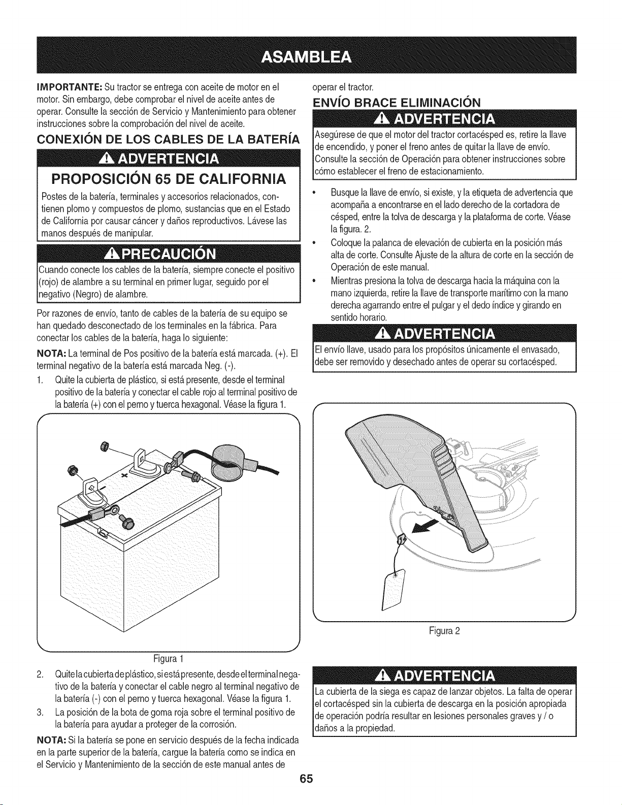
IMPORTANTE: Su tractorseentregaconaceitedemotoren el
motor.Sinembargo,debecornprobarel niveldeaceiteantesde
operar.Consultela secci6nde Servicioy Mantenirnientopara obtener
instruccionessobrela cornprobaci6ndelnivelde aceite.
CONEXION DE LOS CABLES DE LA BATER{A
PROPOSlClON 65 DE CALiFORNiA
Postesdela bateria,terrninalesy accesoriosreladonados,con-
fienen plornoy cornpuestosde plorno,sustanciasqueen el Estado
de Californiaporcausarc_.ncery da5osreproducfivos.L_.veselas
rnanosdespu_sde rnanipular.
Cuandoconecteloscablesde la bateria,siernpreconecteel posifivo
I(rojo)dealarnbrea su terminalenprimerlugar,seguidoporel
pgafivo (Negro)dealarnbre.
Porrazonesde envb, tanto de cablesde la bateriade su equipose
hanquedadodesconectadode los terrninalesen laf_.brica.Para
conectarlos cablesde la bateria,haga Io siguiente:
NOTA: Laterminalde Pospositivode labateriaest,.rnarcada.(+). El
terminalnegativode labateriaest&rnarcadaNeg.(-).
1. Quitela cubiertade pl&stico,si est&presente,desdeelterminal
positivode labateriay conectarelcablerojoalterminalpositivode
labateria(+)conel pernoy tuercahexagonal.Veaselafigura1.
f
/
/
/
/
/
/
/
/
/
/
/
/
/
J
Figura1
2. Quitelacubiertadepl_.stico,siest,,presente,desdeelterminalnega-
tivode labateriay conectarel cablenegroal terminalnegativode
la bater[a(-) con el pernoy tuerca hexagonal.Wase la figura 1.
3. La posici6nde la botade gorna rojasobreel terminalpositivode
la bater[aparaayudara protegerde la corrosi6n.
NOTA: Si labater[ase poneen serviciodespu_sde la fecha indicada
en lapartesuperiorde la bater[a,carguela bater[acornose indicaen
el Servicioy Mantenirnientode la secci6ndeestemanualantesde
operarel tractor.
ENV{O BRACE EUMINACKSN
AsegQresedequeel motordel tractorcortacespedes, retirelaIlave
de encendido,y ponerel frenoantesde quitarla Ilavedeenvio.
IConsultela secci6nde Operaci6nparaobtenerinstruccionessobre
[c6rnoestaNecerel frenode estacionarniento.
•Busquela Ilavedeenvio,siexiste,y laetiquetadeadvertenciaque
acornpa_aa encontrarseenel ladoderechode lacortadorade
cesped,entrelatolvadedescargay la plataforrnade corte.Wase
la figura.2.
Coloquelapalancade elevaci6ndecubiertaen la posici6nrn_.s
altade corte.ConsulteAjustede laalturadecorteenlasecci6nde
Operaci6ndeestemanual.
Mientraspresionalatolvadedescargahaciala rn_.quinacon la
rnanoizquierda,retirela Ilavede transporternar[tirnoconla rnano
derechaagarrandoentreel pulgary el dedoindicey girandoen
sentidohorario.
Elenv[oIlave,usadoparalos prop6sitosQnicarnenteel envasado,
debeser rernovidoy desechadoantesde operarsu cortacesped.
f
Figura2
Lacubiertade la siegaes capazde lanzarobjetos.La faltade operar
el cortac_spedsin lacubiertade descargaen la posici6napropiada
de operaci6npodriaresultarenlesionespersonalesgravesy /o I
[da_osa a propedad. ]
65
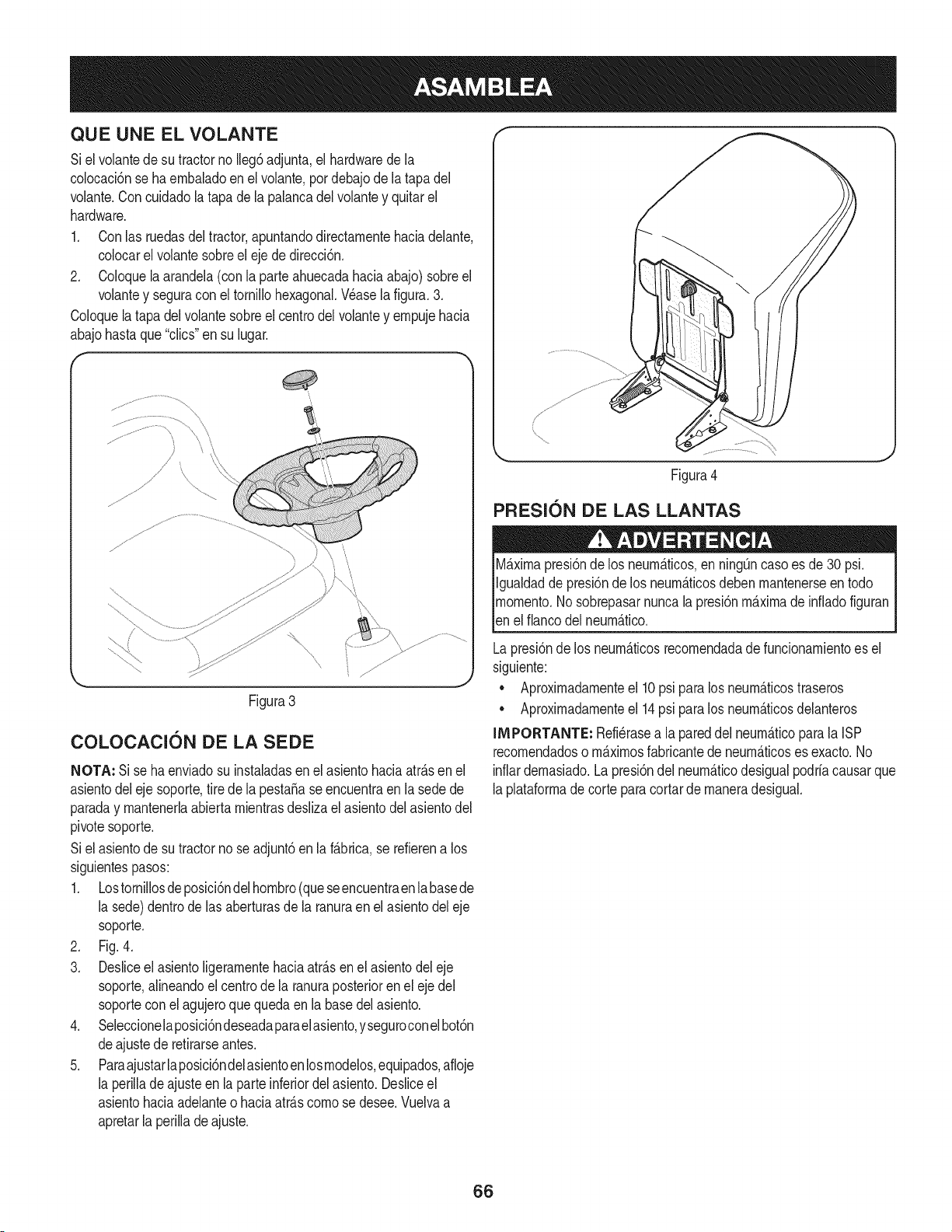
QUE UNE EL VOLANTE
Siel volantedesu tractorno Ileg6adjunta,el hardwarede la
colocaci6nse haembaladoen el volante,pordebajode la tapadel
volante.Concuidadolatapa dela palancadelvolantey quitarel
hardware.
1. Conlas ruedasdel tractor,apuntandodirectamentehaciadelante,
colocarel volantesobreel ejede direcci6n.
2. Coloquela arandela(con la parteahuecadahaciaabajo)sobreel
volantey seguracon el tornillohexagonal.Wase la figura.3.
Coloquela tapadelvolantesobreel centrodelvolantey empujehacia
abajohastaque "clics"ensu lugar.
(
!
// \<
Figura3
COLOCACION DE LA SEDE
NOTA: Si se haenviadosu instaladasen el asientohaciaatrAsen el
asientodeleje soporte,tire de la pesta5ase encuentraen la sedede
paraday mantenerlaabiertamientrasdeslizael asientodelasientodel
pivotesoporte.
Siel asientode sutractorno seadjunt6enla fAbrica,se refierena los
siguientespasos:
1. Lostornillosdeposici6ndelhombro(queseencuentraenlabasede
la sede)dentrode las aberturasde la ranuraen elasientodel eje
soporte.
2. Fig.4.
3. Desliceel asientoligeramentehaciaatrAsenel asientodeleje
soporte,alineandoel centrode la ranuraposterioren el eje del
soporteconel agujeroquequedaen la basedel asiento.
4. Seleccionelaposici6ndeseadaparaelasiento,yseguroconelbot6n
deajustede retirarseantes.
5. Paraajustarlaposici6ndelasientoen losmodelos,equipados,afloje
la perilladeajuste en la parteinferiordel asiento.Desliceel
asientohaciaadelanteo haciaatrAscomo se desee.Vuelvaa
apretarla perillade ajuste.
Figura4
PRESl6N DE LAS LLANTAS
MAximapresi6nde los neurnAticos,en ning_ncasoes de30 psi.
Igualdadde presi6nde los neumAticosdeben mantenerseen todo
momento.Nosobrepasarnuncalapresi6nmaximade infladofiguran
len e f anco de neumAtco.
Lapresi6nde los neumAticosrecomendadade funcionamientoes el
siguiente:
• Aproximadamenteel 10psi para los neumAticostraseros
• Aproximadamenteel 14psi para los neumAticosdelanteros
IMPORTANTE: Refi_rasea la pareddel neumAticoparala ISP
recomendadoso mAximosfabricantede neumAticoses exacto.No
inflardemasiado.Lapresi6ndel neumAticodesigualpodrfacausarque
laplataformade corteparacortarde maneradesigual.
66
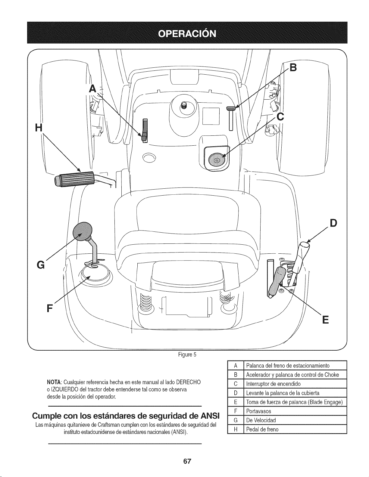
f
A
C
D
E
Figure5
A Palancadel frenode estacionambnto
B Acebradory palancadecontrolde Choke
C Interruptorde encendido
D Levantelapalancade la cubierta
E Tomadefuerza de palanca(Blade Engage)
F Portavasos
G De Velocidad
H Pedalde freno
NOTA:Cualquierreferenciahechaeneste manualal lado DERECHO
o IZQUlERDOdeltractordebeentendersetal comose observa
desdelaposici6ndeloperador.
Cumple con los est_ndares de seguridad de ANSI
Lasm_.quinasquitanievedeCraftsmancumplenconlosest_.ndaresdeseguridaddel
institutoestadounidensede est_.ndaresnacionales(ANSI).
67
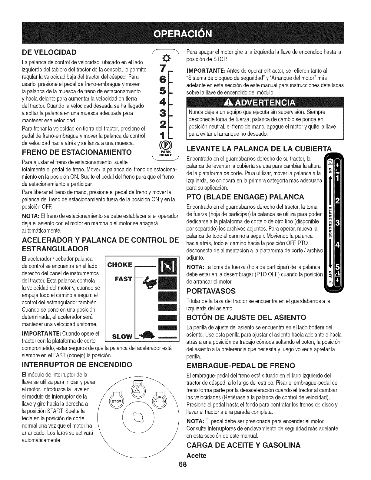
DE VELOCIDAD
La palancadecontrolde velocidad,ubicadoenel lado
izquierdodeltablerodel tractorde la consola,le perrnite
regularlavelocidadbajadel tractordel c_sped.Para
usarlo,presioneel pedalde freno-ernbraguey mover
la palancade larnuescade frenodeestacionarniento
y haciadelanteparaaurnentarlavelocidaden tierra
deltractor.Cuandola velocidaddeseadase ha Ilegado
a soltarla palancaen unarnuescaadecuadapara
rnanteneresavelocidad.
Parafrenarla velocidadentierra del tractor,presioneel
pedalde freno-ernbraguey moverlapalancadecontrol
develocidadhaciaatr_.sy se lanzaa una rnuesca.
FRENO DE ESTACIONAMIENTO
Paraajustarel frenode estacionarniento,suelte
totalrnenteelpedaldefreno.Moverla palancadel frenode estaciona-
rnientoenla posici6nON. Suelteel pedal del frenopara que el freno
deestacionarnientoa participar.
Paraliberarel frenode rnano,presioneel pedaldefreno y moverla
palancadelfreno de estacionarnientofuera dela posici6nONyen la
posici6nOFE
NOTA: Elfrenode estacionarnientosedebeestablecersi el operador
dejael asientocon el motorenrnarchao el motorse apagar_.
autorn_.ticarnente.
ACELERADOR Y PALANCA DE CONTROL DE
ESTRANGULADOR
Elacelerador/cebadorpalanca
decontrol seencuentraenel lado
derechodel paneldeinstrurnentos
deltractor.Estapalancacontrola
lavelocidaddelmotory, cuandose
ernpujatodo elcarninoa seguir,el
controldelestranguladortarnbi_n.
Cuandose poneen una posici6n
deterrninada,el aceleradorser_.
rnantenerunavelocidaduniforrne.
IMPORTANTE: Cuandoopereel
tractorcon la plataforrnadecorte SLOW
comprornetido,estarsegurosdeque la palancadel aceleradorest,.
siernpreen el FAST(conejo)la posici6n.
INTERRUPTOR DE ENCENDIDO
El rn6dulodeinterruptorde la
Ilavese utilizaparainiciary parar
el motor.IntroduzcalaIlaveen
el rn6dulode interruptorde la
Ilavey girehaciala derechaa
la posici6nSTART.Sueltela
teclaen la posici6nde corte
normalunavezqueel motorha
arrancado.Losfarosse activate.
autorn_.ticarnente.
Paraapagarel motorgirea la izquierdala Ilavedeencendidohasta la
posici6nde STOR
IMPORTANTE: Antesde operarel tractor,se refierentanto al
"Sisternade bloqueode seguridad"y "Arranquedelmotor"rn_.s
adelanteen estasecci6nde este manualparainstruccionesdetalladas
sobrela Ilavedeencendidodel rn6dulo.
Nuncadejea un equipoque ejecutasin supervisi6n.Siernpre
desconectetornadefuerza,palancade carnbiose pongaen
posici6nneutral,el frenode rnano,apagueel motory quitela Ilave
paraevitarel arranqueno deseado.
LEVANTE LA PALANCA DE LA CUBIERTA
Encontradoenel guardabarrosderechodesu tractor,la
palancadelevantarlacubiertase usa para carnbiarla altura
de la plataforrnadecorte. Parautilizar,moverla palancaa la
izquierda,secolocar_,en laprirneracategoriarn_.sadecuada
parasu aplicaci6n.
PTO (BLADE ENGAGE) PALANCA
Encontradoenel guardabarrosderechodeltractor,la torna
de fuerza(hojade participar)la palancase utilizaparapoder
dedicarsea laplataforrnade corte o de otrotipo (disponible
por separado)los archivosadjuntos.Paraoperar,rnuevala
palancadetodoel carninoa seguir.Moviendola palanca
haciaatr_.s,todo elcarninohacia la posici6nOFF PTO
desconectade alirnentaci6na la plataforrnade corte/ archivo
adjunto.
NOTA: Latornade fuerza (hojade participar)de la palanca
debeestar en la desernbragar(PTOOFF)cuandola posici6n
de arrancarel motor.
PORTAVASOS
Titularde la tazadel tractorse encuentraenel guardabarrosa la
izquierdadelasiento.
BOTON DE AJUSTE DEL ASIENTO
Laperillade ajustedel asientose encuentraen el ladobotterndel
asiento.Useestaperilla paraajustarel asientohaciaadelanteo hacia
atr_.sa unaposici6ndetrabajoc6rnodasoltandoel bot6n,la posici6n
del asientoa lapreferenciaque necesitay luegovolvera apretarla
perilla.
EMBRAGUE-PEDAL DE FRENO
Elernbrague-pedaldel frenoest,. situadoen el lado izquierdodel
tractordecesped,a Iolargodelestribo.Pisarelernbrague-pedalde
frenoforrnaparteporla desaceleraci6ncuandoel tractoralcarnbiar
las velocidades(Refi_rasea lapalancadecontrolde velocidad).
Presioneel pedalhastael rondoparacontratarlos frenosde discoy
Ilevarel tractora unaparadacornpleta.
NOTA: Elpedaldebeser presionadaparaencenderel motor.
ConsulteInterruptoresdeenclavarnientode seguridadrn_.sadelante
en estasecci6nde este manual.
CARGA DE ACEITE Y GASOLINA
Aceite
68
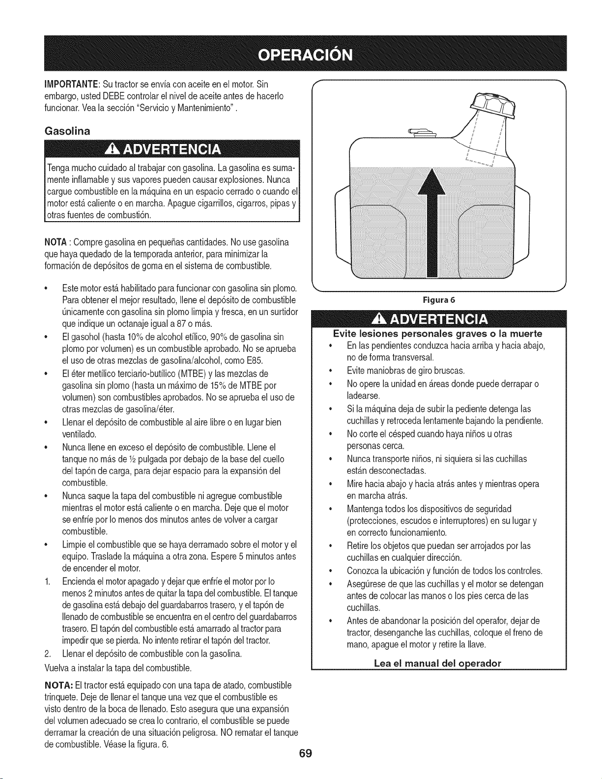
IMPORTANTE:Sutractorse enviacon aceiteen el motor.Sin
embargo,ustedDEBEcontrolarel nivelde aceiteantesde hacerlo
funcionar.Vealasecci6n"Servicioy Mantenirniento".
Gasolina
Tengarnuchocuidadoal trabajarcon gasolina.La gasolinaes surna-
rnenteinfiarnabley susvaporespuedencausarexplosiones.Nunca
carguecombustibleenla rn_.quinaen un espaciocerradoo cuandoel
motorest,.calienteo en rnarcha.Apaguecigarrillos,cigarros,pipasy
otrasfuentesde cornbusti6n.
NOTA: Cornpregasolinaen peque_ascantidades.No usegasolina
quehayaquedadode la ternporadaanterior,pararninirnizarla
forrnaci6nde dep6sitosdegornaen el sisternade combustible.
• Estemotorest,.habilitadoparafuncionarcongasolinasin plorno.
Paraobtenerelrnejorresultado,Ileneel dep6sitode combustible
Onicarnentecongasolinasin plornolirnpiay fresca,enun surtidor
queindiqueun octanajeigual a 87 o rn_.s.
• Elgasohol(hasta10%dealcoholetilico,90%de gasolinasin
plornoporvolurnen)es un combustibleaprobado.No seaprueba
el usode otrasrnezclasdegasolina/alcohol,cornoE85.
• El_ter rnetilicoterciario-butilico(MTBE)y las rnezclasde
gasolinasin plorno(hastaun rn_.xirnode 15%de MTBEpor
volurnen)son combustiblesaprobados.Nose apruebael uso de
otrasrnezclasdegasolina/eter.
• Llenarel dep6sitode combustibleal airelibre o en lugar bien
ventilado.
• NuncaIleneenexcesoeldep6sitode combustible.Lleneel
tanqueno rn_.sde1/2pulgadapor debajode la basedel cuello
deltap6nde carga,paradejarespacio parala expansi6ndel
combustible.
• Nuncasaquelatapa delcombustibleni agreguecombustible
rnientrasel motorest,.calienteo en rnarcha.Dejeque el motor
se enfrieporIo rnenosdos rninutosantesde volvera cargar
combustible.
• Lirnpieelcombustiblequese hayaderrarnadosobreel motory el
equipo.Trasladela rn_.quinaa otra zona. Espere5 rninutosantes
deencenderel motor.
1. Enciendael motorapagadoy dejarqueenfrieelmotorpot Io
rnenos2 rninutosantesdequitarla tapadel combustible.Eltanque
degasolinaest,.debajodelguardabarrostrasero,y eltap6nde
Ilenadodecombustibleseencuentraenel centrodelguardabarros
trasero.Eltap6ndelcombustibleest,.arnarradoal tractorpara
irnpedirquese pierda.Nointenteretirarel tap6ndel tractor.
2. Llenarel dep6sitode combustiblecon la gasolina.
Vuelvaa instalarlatapa del combustible.
NOTA: Eltractorest,.equipadocon unatapade atado,combustible
trinquete.DejedeIlenarel tanqueunavez que el combustiblees
vistodentrode labocade Ilenado.Estoaseguraqueuna expansi6n
delvolurnenadecuadose crea Iocontrario,el combustiblese puede
derrarnarlacreaci6nde una situaci6npeligrosa.NO rernatarel tanque
decombustible.Wase lafigura.6. 69
Figura 6
Evite lesiones personaJes graves ola muerte
•Enlas pendientesconduzcahaciaarribay haciaabajo,
node forrnatransversal.
•Eviternaniobrasdegirobruscas.
•Nooperelaunidaden _.reasdondepuedederraparo
ladearse.
•Sila rn_.quinadejade subirla pedientedetengalas
cuchillasy retrocedalentarnentebajandola pendiente.
•Nocorteel c_spedcuandohayani_osu otras
personascerca.
•Nuncatransporteni_os,nisiquierasi las cuchillas
est_.ndesconectadas.
•Mirehaciaabajoy haciaatr_.santesy rnientrasopera
en rnarchaatr_.s.
•Mantengatodoslos dispositivosde seguridad
(protecciones,escudose interruptores)en su lugary
en correctofuncionarniento.
•Retirelosobjetosquepuedanser arrojadospor las
cuchillasen cualquierdirecci6n.
•Conozcala ubicaci6ny funci6nde todoslos controles.
•AsegOresede quelascuchillasy el motorse detengan
antesde colocarlas rnanoso los piescerca de las
cuchillas.
•Antesde abandonarla posici6ndel operafor,dejarde
tractor,desenganchelas cuchillas,coloqueel frenode
rnano,apagueel motory retirela Ilave.
Lea el manual del o erador
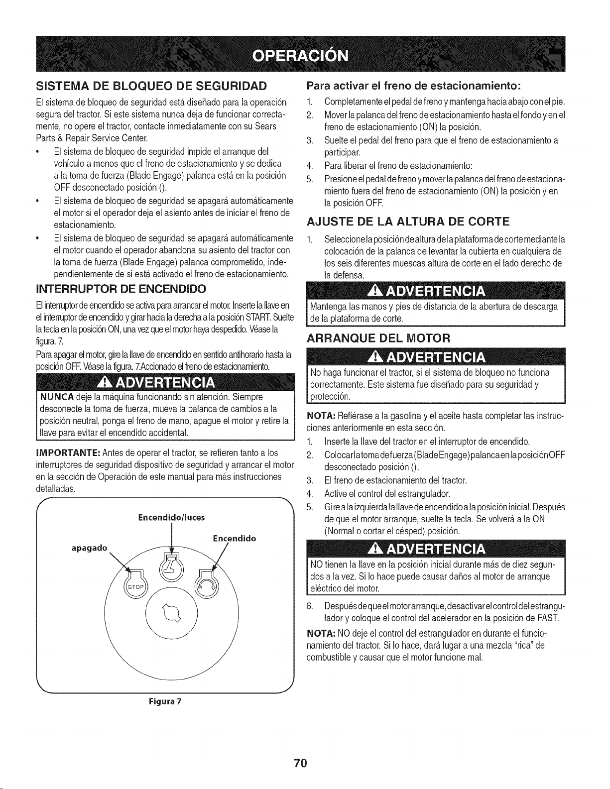
SISTEMA DE BLOQUEO DE SEGURIDAD
El sisternade bloqueode seguridadest,.dise_adoparala operaci6n
seguradel tractor.Si estesisternanuncadejadefuncionarcorrecta-
rnente,noopere el tractor,contacteinrnediatarnentecon su Sears
Parts& RepairServiceCenter.
• El sisternade bloqueode seguridadirnpideel arranquedel
vehiculoa rnenosque elfrenode estacionarnientoy se dedica
a latornadefuerza(Blade Engage)palancaest,. en la posici6n
OFFdesconectadoposici6n0.
• El sisternade bloqueode seguridadseapagar_,autorn_.ticarnente
el motorsi el operadordejael asientoantesde iniciarel frenode
estacionarniento.
• El sisternade bloqueode seguridadseapagar_,autorn_.ticarnente
el motorcuandoel operadorabandonasuasientodel tractorcon
latornade fuerza(BladeEngage)palancacornprornetido,inde-
pendienternentede si est,. activadoel frenode estacionarniento.
INTERRUPTOR DE ENCENDIDO
Elinterruptordeencendidoseactivaparaarrancarel motor.InsertelaIlaveen
elinterruptordeencendidoy girarhacialaderechaa laposicbnSTART.Suelte
latedaenlaposici6nON,unavezqueel motorhayadespedido.Wasela
figura.7.
Paraapagarel motor,girela Ilavedeencendidoensentidoantihorariohastala
_osici6nOFEWaselafigura.7.Accionadoelfrenodeestacionarniento.
NUNCA dejela rn_.quinafundonandosinatenci6n.Siernpre
desconectelatornade fuerza,rnuevala palancade carnbiosa la
posici6nneutral,pongael frenode rnano,apagueel motory retirela
llaveparaevitarelencendidoaccidental.
IMPORTANTE: Antesde operarel tractor,se refierentantoa los
interruptoresde seguridaddispositivode seguridady arrancarel motor
en lasecci6nde Operaci6nde estemanualpararn_sinstrucciones
detalladas.
Encendido/luces
apagado
Encendido
Para activar el freno de estacionamiento:
1. Cornpletarnenteelpedaldefrenoy rnantengahaciaabajoconel pie.
2. Moverlapalancadelfrenode estacionarnientohastael rondoyen el
frenode estacionarniento(ON)la posici6n.
3. Suelteel pedaldel frenoparaque el frenode estacionarnientoa
participar.
4. Paraliberarel frenode estacionarniento:
5. Presioneelpedaldefrenoyrnoverlapalancadelfrenodeestaciona-
rnientofueradel frenodeestacionarniento(ON) laposici6ny en
la posicidnOFE
AJUSTE DE LA ALTURA DE CORTE
Seleccionelaposici6ndealturadelaplataforrnadecorternediantela
colocaci6nde lapalancade levantarla cubiertaen cualquierade
los seisdiferentesrnuescasalturadecorteen elladoderechode
la defensa.
Mantengalas rnanosy pies dedistanciade la aberturade descarga
de laplataforrnade corte.
ARRANQUE DEL MOTOR
Nohagafuncionarel tractor,si elsisternade bloqueono funciona
correctarnente.Estesisternarue dise_adoparasu seguridady
protecci6n.
NOTA: Refi_rasea lagasolinay el aceitehastacornpletarlas instruc-
cionesanteriorrnenteenesta secci6n.
1. Insertela Ilavedel tractoren el interruptorde encendido.
2. Colocarlatornadefuerza(BladeEngage)palancaenlaposici6nOFF
desconectadoposici6n0.
3. Elfrenodeestacionarnientodel tractor.
4. Activeel controldel estrangulador.
5. Girealaizquierdalallavedeencendidoala posicidninicial.Despu_s
de queel motorarranque,sueltela ted& Se volver_,a la ON
(Normalo cortarelcesped)posicidn.
NOtienenla Ilaveen la posici6ninicialdurantern_.sdediez segun-
dos a lavez. SiIo hacepuedecausarda_osal motorde arranque
el_ctricodel motor.
6. Despu_sdequeelrnotorarranque,desactivarelcontroldelestrangu-
ladory coloqueel control del aceleradoren la posicidnde FAST.
NOTA: NOdejeel controldelestranguladoren duranteel funcio-
narnientodel tractor.Si Io hace,dar_.lugara unarnezcla"rica"de
combustibley causarqueel motorfuncionernal.
J
Figura 7
70
PARO DEL MOTOR
Si segolpeaunobjetoextra,o, detengael motor,desconecteel
cablede labujfa(s) y tierracontrael motor.Inspeccionarcuidadosa-
rnenteel equipodelos da_os. Reparaci6ndelos da_osantesde
reiniciary de funcionarniento.
.
3.
Sisededicanalas hojas,colocarlatornadefuerza(Blade Engage)
palancaen laposici6nOFF desconectadoposici6nO.
Girea laizquierdala Ilavede encendidoa la posici6nSTOR
Retirela Ilavedela Ilavede encendidopara evitarel arranqueno
deseado.
LA CONDUCCION DEL TRACTOR
Evitecornienzapronto,el excesode velocidady paradasbruscas.
Nodejeel asientodel tractor,sincolocarlatornadefuerza (Blade
Engage)palancaen laposici6nOFF desernbragar0 posici6n,
presionandoel pedalde frenoy accionadoel frenode estaciona-
rniento.Si no puedesalirdel tractorsin vigilancia,tarnbi_na suvez
la Ilavedeencendidoapagadoy quitarla Ilave.
Siernpremirehaciaabajoy detr_.santesy durantelacopiade
seguridadparaevitarla copiade rn_.sde unaccidente.
Pisarel ernbrague-pedaldefreno paraliberarel frenode estaciona-
rnientoy dejarque el pedal.
Moverlapalancadel aceleradorenel FAST(conejo)la posici6n.
Coloquelapalancadecarnbiostanto en la posici6ninversao
FORWARD.
IMPORTANTE:NOutilizarla palancade carnbiosparacarnbiarla
direcci6nde larnarchacuandoel tractorest_en rnovirniento.Siernpre
utiliceelfreno depedal de ernbragueparaque el tractora una parada
cornpletaantesde pasar.
Suelteel frenodeestacionarnientopresionandoel ernbrague-pedalde
frenoy el posicionarnientode la palancade controldevelocidaden la
posici6ndeseada.
EnprimerlugarIMPORTANTE:-tiernpo,losoperadoresdebenutilizar
posicionesdevelocidadde 1o 2. Convi_rtetetotalrnentefarniliarizado
con el funcionarnientodeltractory loscontrolesantes de operarel
tractoren lospuestosde mayorvelocidad.
Ernbrague-pedalde freno lentarnenteparacolocarlaunidaden
rnovirniento.
Eltractorde c_spedes Ilevadoa una paradapresionandoel
ernbrague-pedalde freno.
NOTA:Cuandooperela unidadinicial,habr_,pocadiferenciaentrelas
dos velocidadesrn_.saltashastadespu_sde los cinturonesse ban
sentadoen laspoleasduranteel periodode rodaje.
Antesde abandonarla posici6ndel operadorpor cualquierraz6n,
separarlashojas,ponerla palancadecontrol de velocidaden
neutral,pongael frenodeestacionarniento,paradamotorapagadoy
quitarla Ilave.
IMPORTANTE:AI pararel tractor,por cualquierrnotivo,rnientrasque
en unasuperficiede hierba,siernpre:
1. Coloquela palancade carnbiosen puntornuerto,
2. Apliqueel frenode estacionarniento,
3. Apagueel motory quitarla Ilave.Si Io hace,reducir_,al rninirnola
posibilidaddequesu c_spedsedore'"'porel escapecalientedel
motordesu tractor.
71
Si seestancala unidadconel controldevelocidadenalta velocidad,
o si la unidadnofuncionar_,con la palancade control de velocidaden
condicionesde bajavelocidad,sigaestos pasos:
1. La palancade carnbiosen puntornuerto.
2. Reinicieel motor.
3. Coloquela palancade control de velocidaden la posici6nrn_.s
altavelocidad.
4. Ernbrague-pedaldefrenocornpletarnente.
5. Pisarel ernbrague-pedalde freno.
6. Coloquela palancade control de velocidaden la posici6n
deseada.
7. Coloquela palancade carnbiosen cualquieradeavanceo retro-
ceso,y seguirlos procedirnientosnorrnalesde funcionarniento.
CONDUCCION EN LAS LADERAS
Refierenal anchodela pendienteen la seguridadde las pr_.cticasde
operaci6nirnportantesecci6ndelmanualparaayudara deterrninar
zonasde laderadondepuedeoperar el tractorcon total seguridad.
No corteel cespeden pendientescon una inclinaci6nde rn_.sde 15
grados(un aurnentodeaproxirnadarnente2-1/2pies cada 10pies).
Eltractorpuedevolcary causarlesionesgraves.
INVOLUCRAR A LOS BLADES
Participaci6ndelatornadefuerza(BladeEngage)lastransferenciasde
energiaa la plataforrnade corteo de otto tipo(disponiblepot separado)
los archivosadjuntos.Paraparticipardelas hojas,haga Iosiguiente:
1. Moverla palancade controldel aceleradora la r_.pida(conejo)la
posici6n.
2. Sujetelatornadefuerza(BladeEngage)ygirarla palancadetodoel
carninoa seguira los novios(ON) la posici6n.
3. Mantengalapalancadelaceleradorenel FAST(conejo)la posici6n
parael uso rn_.seficientede la plataforrnade corteo deotro tipo
(disponibleporseparado)los archivosadjuntos.
IMPORTANTE: Enel reversoPrecauci6nrnodoque el motorse
apagar_,autorn_.ticarnentesi latornadefuerzaest,.comprornetidacon
la palancade controldevelocidaden la posici6ninversaparaviajar
con la Ilavedeencendidoenla posici6nnormalde siega.
USO DE LA CUBIERTA DE LEVANTE LA
PALANCA DE
Paraelevarlaplataforrnade corte,moverla palancadeelevaci6nde
cubiertaa la izquierda,luegosecoloca en la ranurarn_.sadecuada
parasu aplicaci6n.ConsulteAjustelaalturade corte anteriorrnenteen
estasecci6n.
• Corteel cespedy las pendientes,nuncatransversal.
Tengaextrernaprecauci6nal carnbiarde direcci6nen las
pendientes.
• Watchparalos agujeros,grietas,baches,piedrasu otrosobjetos
ocultos.Terrenoirregularpuederevertirla rn_.quina.El c_sped
alto puedeocultarobst_.culos.
Evitegirarcuandosecirculaporuna pendiente.Si una vez,debe
hacerse,a suvezpor la pendiente.Elregresodeuna pendiente
aurnentala posibilidadde un rollover.
Evitedetenersecuandose conducepot unapendiente.Si es
necesariodetenerrnientrasse conducepot unapendiente,
puestaen rnarchasin problernasy con cuidadoparareducirla
posibilidadde volteareltractorhaciaatr_.s.
72
CORTAR
ParaayudaraevJtarelcontactocon lacuchJllao una lesJ6nen
elobjetolanzado,Mantengaa losespectadores,losayudantes,
los niSosy las rnascotasporIo rnenos75 piesde distanciade la
rn_.quinarnientrasest,.en funcionarniento.Paradade la rn_.quina,si
alguienentraenel _.rea.
La siguienteinforrnaci6nser_.Qtilcuandose utilizala plataforrnade
cortecon sutractor:
Plande su patr6nde corte para evitarla descargade rnateriales
hacialas carreteras,aceras,transeQntes,etc.Adern_.s,evitematerial
quese descargacontra una paredo una obstrucci6nque puede
causaraltamateriala rebotarhaciael operador.
FAROS
• LasI_.rnparasest_.nONcuandoel motordeltractorse est,.
ejecutando.
• Laslucesse apagacuandolaIlavedecontactose rnuevea la
posici6nSTOR
• No corteel c6speda la velocidadde terrenoelevado,especial-
rnentesi se ha instaladoun kit de rnantilloo colectorde cesped.
• Paraobtenerlos rnejoresresultadosse recorniendaquelas
dos primerasvueltassecortar&con laaprobaci6nde la gesti6n
arrojadohaciael centro.Traslasdos prirnerasvueltas,invertirel
sentidodelanzarla descargahaciael exteriorde la balanzade
corte.Estoledar&unarnejoraparienciaal c6sped.
• Nocorteelc6speddernasiadocorto.Pastocorto invitacrecirniento
dernalashierbasy losarnarilloscon rapidezenel tiernposeco.
Cortarel c6spedsiernprese debehacercon el motora todogas.
• Bajolascondicionesrn_.spesadas,puedeser necesariovolver
sobrelazonadel corteporsegundavezpara obtenerun corte
lirnpio.
• NOintentecortarespesarnalezay rnalashierbasyelpastornuyalto.
Sutractorest_dise_adoparacortarelc6sped,uncepillonoest_claro.
• Mantengalascuchillasafiladasy sustituirlascuchillasencaso
dedesgaste.ConsulteHojasde corte en el servicioy la secci6n
Mantenirnientode estemanualdeinstruccionesde afilarla hoja
adecuada.
73
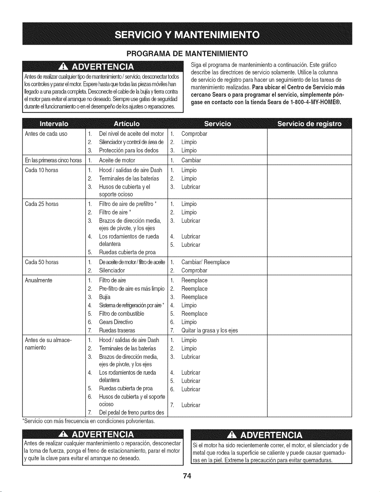
PROGRAMA DE iVlANTENIIVllENTO
Antesderealizarcualquiertipodernantenirniento/servicio,desconectartodos
loscontrolesy pararelmotor.Esperehastaquetodaslaspiezasrn6vilesban
Ilegadoa unaparadacornpleta.Desconecteelcablede labujfay tierracontra
elmotorparaevitarelarranquenodeseado.Siernpreusegalasdeseguridad
duranteelfuncionarnientooeneldesernpeSode losajustesoreparaciones.
Sigael prograrnade rnantenirnientoa continuaci6n.Estegr_.fico
describelas directricesde serviciosolarnente.Utilicelacolurnna
de serviciode registroparahacerunseguirnientode las tareasde
rnantenirnientorealizadas.Paraubicar el Centro de Servicio m_s
cercanoSearso paraprogramarel servicio,simplementep6n-
gase eneontactocon latienda Searsde 1-800-4-MY-HOME®.
Antesde cadauso
Enlasprirnerascincohoras
Cada10horas
Cada25horas
Cada50horas
Anualrnente
Antesde sualrnace-
narniento
1. Delnivelde aceitedel motor
2. Silenciadory controlde_.reade
3. Protecci6nparalosdedos
1. Aceitede motor
1. Hood/salidasde aireDash
2. Terrninalesde las baterias
3. Husosde cubiertayel
soporteocioso
1. Filtrode aire de prefiltro*
2. Filtrode aire *
3. Brazosdedirecci6nmedia,
ejes de pivote,y los ejes
4. Losrodarnientosderueda
delantera
5. Ruedascubiertadeproa
1. Deaceitedemotor/liltrodeaceite
2. Silenciador
1. Filtrodeaire
2. Pre-filtrode airees rn_.slirnpio
3. Bujia
4. Sisternaderefrigeraci6nporaire*
5. Filtrodecombustible
6. GearsDirectivo
7. Ruedastraseras
1. Hood/salidasdeaire Dash
2. Terrninalesde lasbaterias
3. Brazosdedirecci6nmedia,
ejesdepivote,y losejes
4. Losrodarnientosderueda
delantera
5. Ruedascubiertade proa
6. Husosde cubiertay el soporte
ocioso
7. Delpedaldefrenopuntosdes
1. Cornprobar
2. Lirnpio
3. Lirnpio
1. Carnbiar
1. Lirnpio
2. Lirnpio
3. Lubricar
1. Lirnpio
2. Lirnpio
3. Lubricar
4. Lubricar
5. Lubricar
1. Carnbiar/Reernplace
2. Cornprobar
1. Reernplace
2. Reernplace
3. Reernplace
4. Lirnpio
5. Reernplace
6. Lirnpio
7. Quitarla grasay los ejes
1. Lirnpio
2. Lirnpio
3. Lubricar
4. Lubricar
5. Lubricar
6. Lubricar
7. Lubricar
3iel.Extremela 3recauclon
*Serviciocon rn_.sfrecuenciaencondicionespolvorientas.
Antesde realizarcualquierrnantenirnientoo reparaci6n,desconectar
latornadefuerza,pongael frenode estacionarniento,parar el motor
y quitela clavepara evitarel arranqueno deseado. evitar uernaduras.
74
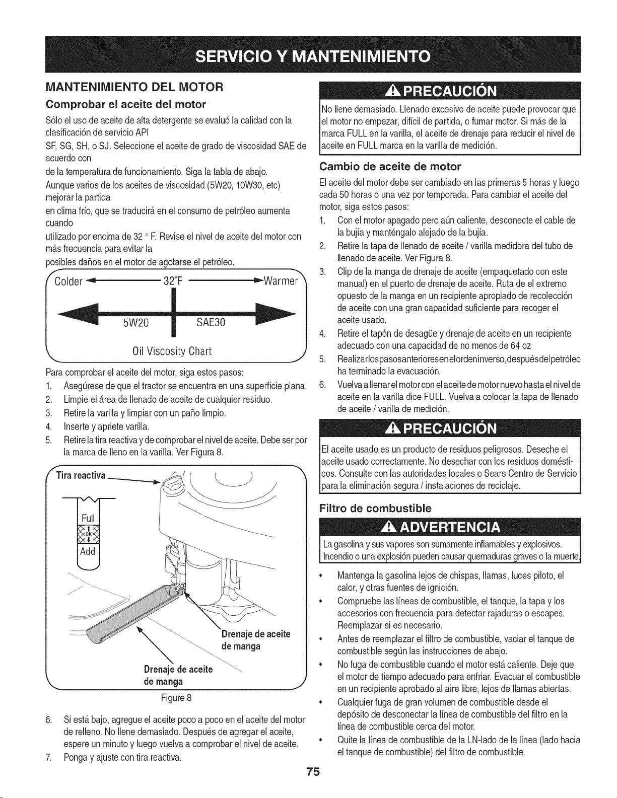
iVlANTENIIVllENTODEL MOTOR
Comprobar el aceite del motor
$61oeluso de aceite de alta detergenteseevalu6la calidadcon la
clasificaci6nde servicioAPI
SF,SG,SH,o SJ. Seleccioneel aceitede gradode viscosidadSAEde
acuerdocon
dela ternperaturade funcionarniento.Siga la tabla de abajo.
Aunquevariosde los aceitesde viscosidad(5W20,10W30,etc)
rnejorarla partida
enclirnafrio,quese traducir_,enel consurnode petr61eoaurnenta
cuando
utilizadoporencirnade 32 oR Reviseel nivelde aceite delmotorcon
rn_.sfrecuenciaparaevitarla
_osiblesda_osen el motordeagotarseel petr61eo.
Colder _ 32°F _Warmer
Oil Viscosity Chart
Paracornprobarel aceitedel motor,sigaestospasos:
1. AsegQresede queel tractorseencuentraen una superficieplana.
2. Lirnpieel _.reade Ilenadode aceitede cualquierresiduo.
3. Retirela varillay lirnpiarcon un pasolirnpio.
4. Insertey aprietevarilla.
5. Retirela tira reactivayde cornprobarelniveldeaceite.Debesetpor
la rnarcadeIlenoen lavarilla.Vet Figura8.
fTira reactiva_ ___ "_
•
Drenajede aceite
de manga
Drenajede aceite
de manga j
Figure8
6. Si est,. bajo,agregueel aceite pocoa pocoen el aceite del motor
de relleno.No Ilenedernasiado.Despu_sde agregarel aceite,
espereun rninutoy luego vuelvaa cornprobarel nivelde aceite. "
7. Pongay ajustecon tira reactiva.
75
No Ilenedernasiado.Llenadoexcesivode aceite puedeprovocarque
el motornoernpezar,diffcilde partida,o furnarmotor.Si rn_.sdela
rnarcaFULLen lavarilla,el aceitede drenajeparareducirel nivelde
aceiteen FULLrnarcaen la varilladernedici6n.
Cambio de aceite de motor
Elaceitedel motordebe set carnbiadoen las prirneras5 horasy luego
cada50 horaso unavezporternporada.Paracarnbiarel aceitedel
motor,sigaestospasos:
1. Conel motorapagadopero aQncaliente,desconecteel cablede
labujiay rnant_ngaloalejadode la buj[a.
2. Retirela tapade Ilenadode aceite/varillarnedidoradel tubo de
Ilenadode aceite.Vet Figura8.
3. Clipde la rnangade drenajede aceite (ernpaquetadocon este
manual)en el puertodedrenajedeaceite.Rutade el extrerno
opuestode larnangaen un recipienteapropiadode recolecci6n
de aceitecon unagrancapacidadsuficientepara recogerel
aceiteusado.
4. Retireel tap6nde desag(Jey drenajedeaceite en un recipiente
adecuadocon unacapacidaddeno rnenosde64 oz
5. Realizarlospasosanterioresenelordeninverso,despu_sdelpetr61eo
haterrninadolaevacuaci6n.
6. VuelvaaIlenarelrnotorconelaceitede motornuevohastael nivelde
aceiteen la varilladice FULL.Vuelvaa colocarlatapa de Ilenado
de aceite/varillade rnedici6n.
Elaceiteusadoes un productode residuospeligrosos.Desecheel
aceiteusadocorrectarnente.Nodesecharcon los residuosdorn_sti-
cos. Consultecon lasautoridadeslocaleso SearsCentrodeServicio
)arala elirninaci6nsegura/instalacionesde reciclaje.
Filtro de combustible
Incendioo _uedencausarcuernaduras(raveso larnuerte
• Mantengala gasolinalejosde chispas,llamas,luces piloto,el
calor,y otrasfuentesdeignici6n.
• Cornpruebelas lineasdecombustible,el tanque,la tapa y los
accesorioscon frecuenciaparadetectarrajaduraso escapes.
Reernplazarsi es necesario.
• Antesde reernplazarelfiltro de combustible,vaciarel tanquede
combustiblesegQnlas instruccionesde abajo.
• Nofuga decombustiblecuandoel motorest,.caliente.Dejeque
el motorde tiernpoadecuadoparaenfriar.Evacuarel combustible
en un recipienteaprobadoal aire libre, lejosdellamasabiertas.
• Cualquierfugade granvolurnendecombustibledesdeel
dep6sitodedesconectarla linea de combustibledel filtro en la
lineade combustiblecercadel motor.
Quitelalineadecombustiblede la LN-ladode la linea (lado hacia
el tanquedecombustible)del filtro de combustible.
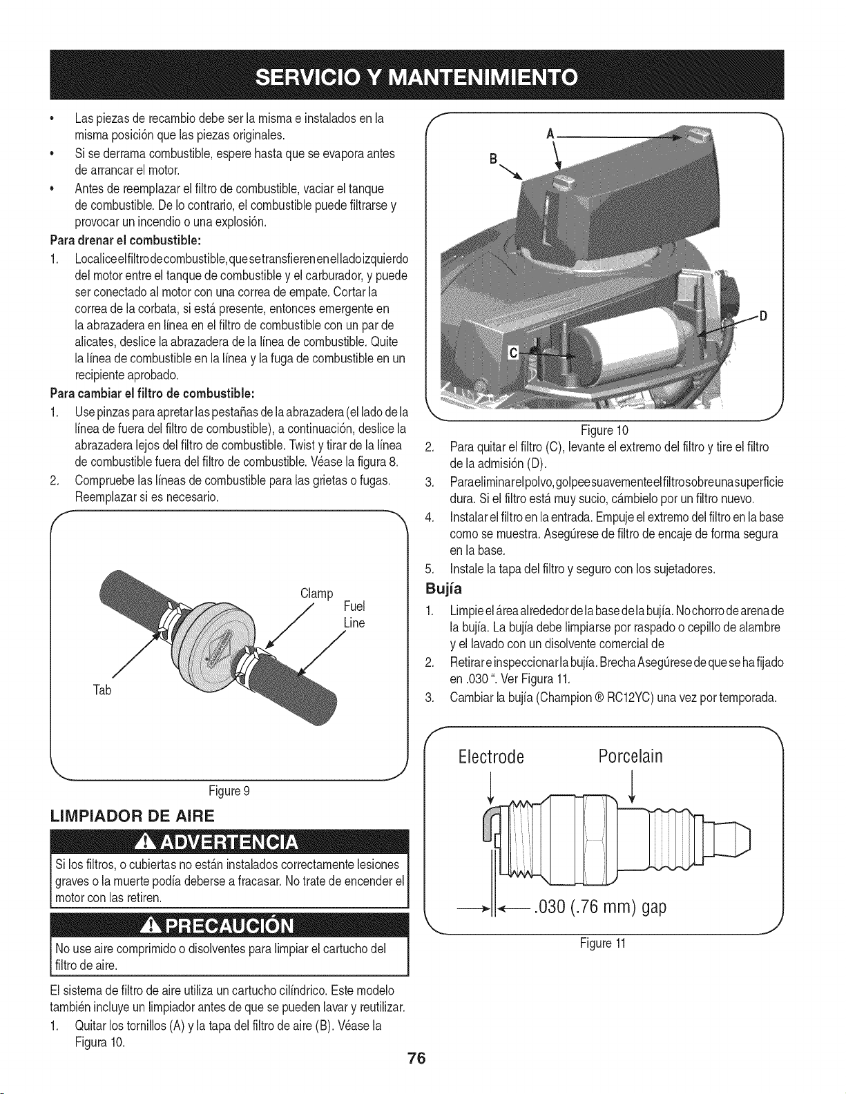
* Laspiezasderecarnbiodebeserlarnisrnaeinstaladosenla
rnisrnaposiciSnquelaspiezasoriginales.
* Sisederrarnacombustible,esperehastaqueseevaporaantes
dearrancarelmotor.
* Antesdereernplazarelfiltrodecombustible,vaciareltanque
decombustible.DeIocontrario,elcombustiblepuedefiltrarsey
provocarunincendioounaexplosi6n.
Paradrenarel combustible:
1. Localiceelfiltrodecornbustible,quesetransfierenenelladoizquierdo
delmotorentreel tanquedecombustibley el carburador,y puede
setconectadoal motorcon una correade ernpate.Cortarla
correade la corbata,si est,.presente,entoncesernergenteen
laabrazaderaenlinea en el filtro de combustiblecon un par de
alicates,deslicela abrazaderade la linea de combustible.Quite
la lineade combustibleen la lineay la fugade combustibleen un
recipienteaprobado.
Paracambiarel filtro de combustible:
1. Usepinzasparaapretarlaspesta_asdelaabrazadera(elladodela
lineade fueradel filtro de combustible),a continuaci6n,deslicela
abrazaderalejosdel filtrodecombustible.Twisty tirarde la linea
decombustiblefueradel filtro de combustible.Wase lafigura8.
2. Cornpruebelaslineasde combustibleparalas grietaso fugas.
Reernplazarsi es necesario.
I"
Clamp Fuel
Line
Tab
_., .J
Figure9
LIMPIADOR DE AIRE
Silos filtros,o cubiertasnoest_.ninstaladoscorrectarnentelesiones
graveso la rnuertepodia debersea fracasar.No tratede encenderel
motorcon las retiren.
f
B
A
Figure10
2. Paraquitarel filtro (C), levanteel extrernodel filtroy tire elfiltro
de laadrnisi6n(D).
3. Paraeliminarelpolvo,golpeesuavernenteelfiltrosobreunasuperficie
dura. Siel filtroest,.rnuysucio,c_.rnbieloporunfiltro nuevo.
4. Instalarelfiltroenla entrada.Ernpujeel extrernodelfiltroenlabase
cornose rnuestra.AsegOresedefiltrode encajedeforrnasegura
en la base.
5. Instalela tapadel filtro y segurocon los sujetadores.
Bujia
1. Lirnpieel_.reaalrededordelabasedelabujia.Nochorrodearenade
la buj[a.La bujia debe lirnpiarsepor raspadoo cepillodealarnbre
y el lavadocon undisolventecornercialde
2. Retirareinspeccionarlabujia.BrechaAsegOresedequesehafijado
en .030". VerFigura11.
3. Carnbiarla bujia (Champion® RC12YC)unavez por ternporada.
Electrode Porcelain
.030 (.76 mm) gap
No useairecornprirnidoo disolventesparalirnpiarel cartuchodel
filtrode aire.
El sisternadefiltrode aireutilizaun cartuchocilindrico.Esternodelo
tarnbi6nincluyeunlirnpiadorantesde que se puedenlavary reutilizar.
1. Quitarlostornillos(A) y la tapadel filtro de aire (B). Wase la
Figura10.
76
Figure11
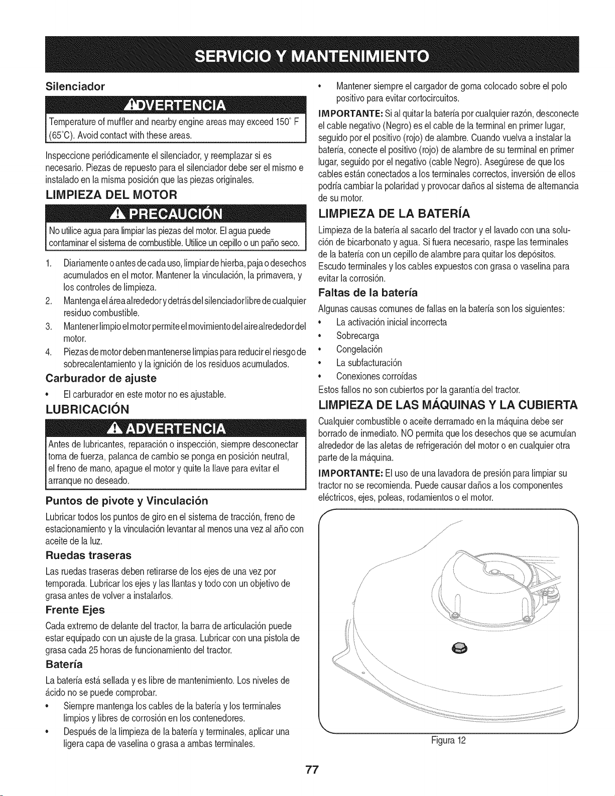
Silenciador
Temperatureof mufflerandnearbyengineareasmayexceed 150° F
(65°0).Avoidcontactwith these areas.
Inspeccioneperi6dicamenteel silenciador,y reemplazarsi es
necesario.Piezasde repuestopara el silenciadordebe ser el mismoe
instaladoen la mismaposici6nque las piezasoriginales.
LIMPIEZA DEL MOTOR
Noutiliceaguaparalimpiarlaspiezasdelmotor.Elaguapuede
contaminarelsistemadecombustible.Utiliceuncepilloo unpasoseco.
1. Diariamenteoantesdecadauso,limpiardehierba,pajaodesechos
acumuladosenel motor.Mantenerla vinculaci6n,la primavera,y
los controlesdelimpieza.
2. Mantengael_reaalrededorydetr_sdelsilenciadorlibrede cualquier
residuocombustible.
3. Mantenerlimpioelmotorpermiteelmovimientodelairealrededordel
motor.
4. Piezasdemotordebenmantenerselimpiasparareducirelriesgode
sobrecalentamientoy la ignici6nde los residuosacumulados.
Carburador de ajuste
• Elcarburadoren estemotorno esajustable.
LUBRICACION
Antesde lubricantes,reparaci6no inspecci6n,siempredesconectar
tomade fuerza,palancadecambio se pongaen posici6nneutral,
elfreno demano,apagueel motory quite la Ilavepara evitarel
arranqueno deseado.
Puntos de pivote y Vinculaci6n
Lubricartodoslos puntosde giro en el sistemade tracci6n,frenode
estacionamientoy la vinculaci6nlevantaral menosunavezalaSocon
aceitede la luz.
Ruedas traseras
Las ruedastraserasdebenretirarsede los ejesde unavez por
temporada.Lubricarlos ejesy las Ilantasy todo con un objetivode
grasaantesde volvera instalarlos.
Frente Ejes
Cadaextremodedelantedeltractor,la barradearticulaci6npuede
estarequipadocon unajustede la grasa. Lubricarcon una pistolade
grasacada25 horasde funcionamientodeltractor.
Bateria
La bateriaest_seiiaday es libredemantenimiento.Losniveiesde
_cidonose puedecomprobar.
• Siempremantengalos cablesde labateriay los terminaies
limpiosy libresde corrosi6nen los contenedores.
• Despu_sdela limpiezade la bateriay terminaies,apiicaruna
ligeracapa devaseiinao grasaa ambasterminaies.
• Mantenersiempreel cargadordegomacolocadosobreel polo
positivoparaevitarcortocircuitos.
IMPORTANTE: Sial quitarla bateriaporcualquierraz6n,desconecte
el cablenegativo(Negro)es el cablede laterminalenprimerlugar,
seguidoporel positivo(rojo) de alambre.Cuandovuelvaa instalarla
bateria,conecteelpositivo(rojo)de alambrede suterminalen primer
lugar,seguidoporel negativo(cableNegro).Aseg0resede que los
cablesest_nconectadosa los terminalescorrectos,inversi6ndeellos
podriacambiarla polaridady provocarda_osal sistemadealternancia
de su motor.
LIMPIEZA DE LA BATERiA
Limpiezadela bateriaal sacarlodel tractory el lavadocon unasolu-
ci6n de bicarbonatoy agua.Si fueranecesario,raspelasterminales
de la bateriacon uncepillodealambreparaquitar losdep6sitos.
Escudoterminalesy los cablesexpuestoscongrasao vaselinapara
evitarlacorrosi6n.
Faltas de la bateria
Algunascausascomunesdefallas en la bateriasonlos siguientes:
• Laactivaci6ninicialincorrecta
• Sobrecarga
• Congelaci6n
• Lasubfacturaci6n
• Conexionescorroidas
Estosfallosnoson cubiertospor la garanfiadel tractor.
LIMPIEZA DE LAS M._.QUINAS Y LA CUBIERTA
Cualquiercombustibleoaceitederramadoen lam_quinadebeser
borradode inmediato.NO permitaque losdesechosque se acumulan
alrededordelas aletasde refrigeraci6ndelmotoro en cualquierotra
partede la m_quina.
INIPORTANTE: El usode unalavadorade presi6nparalimpiarsu
tractorno se recomienda.PuedecausardaSosa los componentes
eBctricos,ejes,poleas,rodamientoso el motor.
f
J
Figura12
77
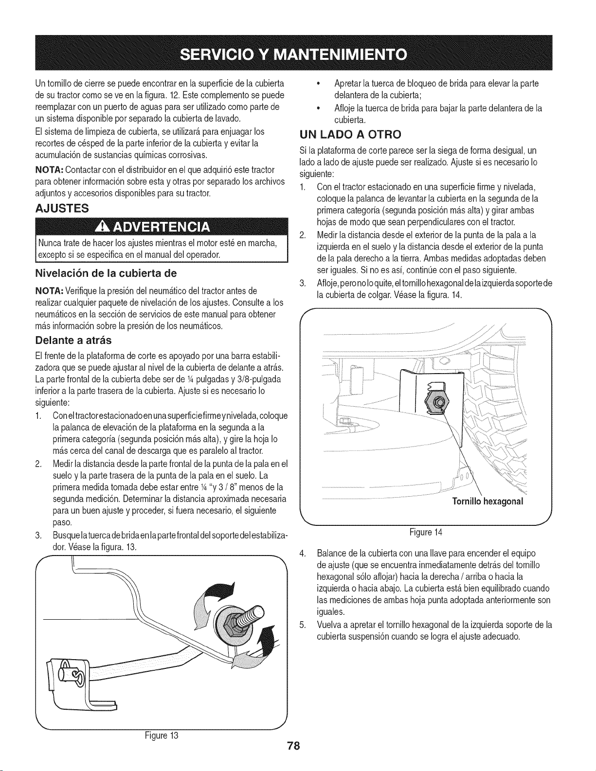
Untornillode cierrese puedeencontraren la superficiede la cubierta
de sutractorcornoseve en lafigura.12.Estecomplernentose puede
reernplazarcon un puertode aguasparaserutilizadocornopartede
un sisternadisponibleporseparadolacubiertade lavado.
El sisternade lirnpiezade cubierta,se utilizar_,paraenjuagarlos
recortesde c_speddela parteinferiordela cubiertay evitarla
acurnulaci6nde sustanciasquirnicascorrosivas.
NOTA: Contactarcon eldistribuidoren el que adquiri6este tractor
paraobtenerinforrnaci6nsobreestay otras por separadolosarchivos
adjuntosy accesoriosdisponiblesparasu tractor.
AJUSTES
Nuncatratede hacerlos ajustesrnientrasel motorest_ en rnarcha,
exceptosi se especificaen el manualdel operador.
Nivelaci6n de la cubierta de
NOTA: Verifiquelapresi6ndel neurn_.ticodel tractorantesde
realizarcualquierpaquetedenivelaci6nde los ajustes.Consultea los
neurn_.ticosen la secci6nde serviciosde estemanualpara obtener
rn_.sinforrnaci6nsobrela presi6nde los neurn_.ticos.
Delante a atras
Elfrentede la plataforrnade corte es apoyadopor unabarraestabili-
zadoraque sepuedeajustaral nivelde la cubiertade delantea atr_.s.
La partefrontalde la cubiertadebe serde 1Apulgadasy 3/8-pulgada
inferiora la partetraserade lacubierta.Ajustesi es necesarioIo
siguiente:
1. Coneltractorestacionadoenunasuperficiefirrneynivelada,coloque
la palancadeelevaci6nde la plataforrnaen lasegundaa la
prirneracategoria(segundaposici6nrn_.salta), y gire la hoja Io
rn_.scercadel canalde descargaque es paraleloal tractor.
2. Medirla distanciadesdela partefrontalde la puntade la pala en el
sueloy la partetraserade la puntade la palaen el suelo.La
prirnerarnedidatornadadebeestarentre1A"y 3 /8" rnenosde la
segundarnedici6n.Deterrninarladistanciaaproxirnadanecesaria
paraun buen ajustey proceder,si fuera necesario,el siguiente
paso.
3. Busquelatuercadebridaenlapartefrontaldelsoportedelestabiliza-
dor.Wase la figura.13.
• Apretarlatuercadebloqueode bridaparaelevarlaparte
delanterade lacubierta;
• Aflojela tuercade bridaparabajarla partedelanterade la
cubierta.
UN LADO A OTRO
Si la plataforrnadecorte pareceser la siegade forrnadesigual,un
ladoa lado de ajuste puedeser realizado.Ajustesi es necesarioIo
siguiente:
1. Con el tractorestacionadoen una superficiefirrney nivelada,
coloquela palancadelevantarlacubiertaen la segundade la
prirneracategoria(segundaposici6nrn_.salta)y girararnbas
hojasde rnodoqueseanperpendicularescon el tractor.
2. Medirla distanciadesdeel exteriorde la puntade la pala a la
izquierdaenel sueloy ladistanciadesdeel exteriordela punta
de la paladerechoa latierra.Arnbasrnedidasadoptadasdeben
ser iguales.Si no es asi, continQeconel pasosiguiente.
3. Afloje,peronoloquite,eltornillohexagonaldelaizquierdasoportede
la cubiertade colgar.Wase lafigura. 14.
Tornillo hexagonal
J
Figure14
4. Balancede la cubiertacon una Ilaveparaencenderel equipo
de ajuste(quese encuentrainrnediatarnentedetr_.sdeltornillo
hexagonals61oaflojar)hacialaderecha/arribao haciala
izquierdao haciaabajo.Lacubiertaest,.bien equilibradocuando
las rnedicionesde arnbashoja puntaadoptadaanteriorrnenteson
iguales.
5. Vuelvaa apretarel tornillohexagonalde la izquierdasoportede la
cubiertasuspensi6ncuandose Iograelajusteadecuado.
Figure13 78
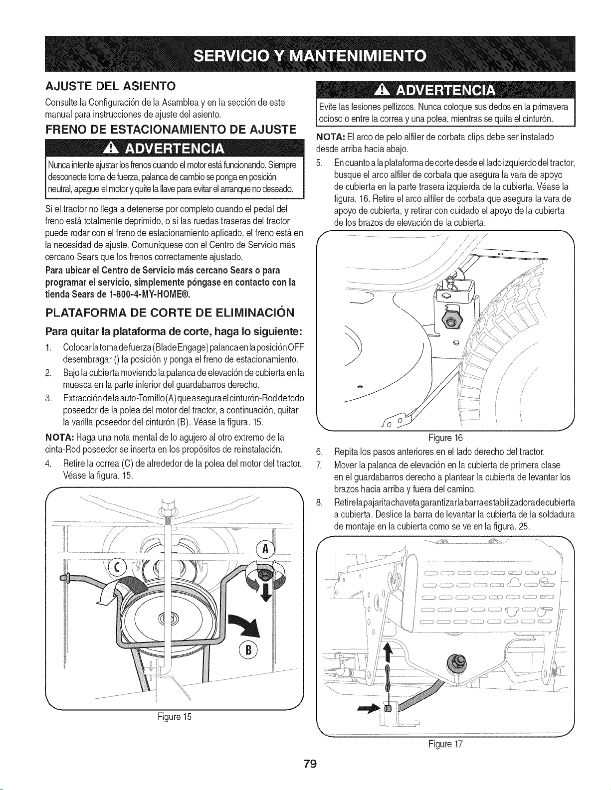
AJUSTE DEL ASIENTO
Consultela Configuraci6nde la Asarnbleay en la secci6nde este
manualparainstruccionesdeajustedel asiento.
FRENO DE ESTACIONAIVlIENTO DE AJUSTE
Nuncaintenteajustarlosfrenoscuandoelmotorest&funcionando.Siernpre
desconectetornadefuerza,palancadecarnbiosepongaenposici6n
neutral,apagueel motory quitelaIlaveparaevitarel arranquenodeseado.
Siel tractornoIlegaa detenerseporcornpletocuandoel pedal del
frenoestfi totalrnentedeprirnido,o si las ruedastraserasdeltractor
puederodarconel frenode estacionarnientoapNcado,el frenoestfi en
la necesidaddeajuste.Cornunfquesecon el Centrode Serviciornfis
cercanoSearsque losfrenoscorrectarnenteajustado.
Paraubicar el Centrode Servicio rn_s cercanoSears o para
programarel servicio,simplementep6ngaseen contactoconla
tienda Searsde 1-800-4-MY-HOME®.
PLATAFORiVlA DE CORTE DE ELIlVlINACl6N
Para quitar la plataforrna de corte, haga Io siguiente:
1. Colocarlatornadefuerza(BladeEngage)palancaenlaposici6nOFF
desernbragar0 la posici6ny pongael frenodeestacionarniento.
2. Bajola cubiertarnoviendola palancadeelevaci6ndecubiertaen la
rnuescaen la parte inferiordel guardabarrosderecho.
3. Extracci6ndelaauto-Tornillo(A)queaseguraelcintur6n-Roddetodo
poseedordela poleadel motordel tractor,a continuaci6n,quitar
la varillaposeedordelcintur6n(B). Wase lafigura.15.
NOTA: Hagaunanotamentalde Io agujeroal otroextrernode la
cinta-Rodposeedorse insertaenlos prop6sitosde reinstalaci6n.
4. Retirela correa(C)de alrededorde la poleadel motor del tractor.
Wase la figura.15.
f
Figure15
Evitelas lesionespellizcos.Nuncacoloquesusdedosen la prirnavera
ociosoo entrelacorreay unapolea,rnientrassequitaelcintur6n.
NOTA: Elarcode peloalfilerde corbataclipsdebe ser instalado
desdearribahaciaabajo.
5. Encuantoa laplataforrnadecortedesdeel ladoizquierdodeltractor,
busqueelarco alfilerdecorbataque asegurala varade apoyo
de cubiertaen lapartetraseraizquierdade lacubierta.Wase la
figura.16.Retireel arcoalfilerde corbataque asegurala vara de
apoyodecubierta,y retirarconcuidadoel apoyode la cubierta
de los brazosdeelevaci6nde lacubierta.
/
/
f
.
7.
J
Figure16
Repitalos pasosanterioresen el lado derechodel tractor.
Moverla )alancade elevaci6nenla cubiertade prirneraclase
en elguardabarrosderechoa plantearla cubiertadelevantarlos
brazoshaciaarribay fueradel carnino.
Retirelapajaritachavetagarantizarlabarraestabilizadoradecubierta
a cubierta.Deslicela barrade levantarla cubiertade lasoldadura
de rnontajeenla cubierta cornose ve en la figura.25.
-..,,
ii ti
Figure17
79
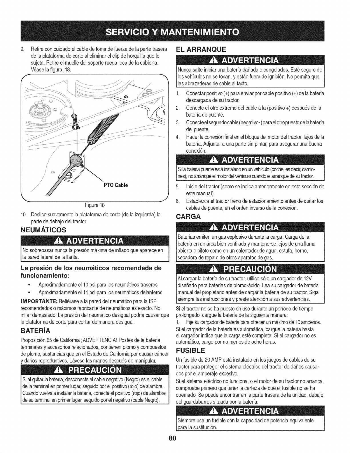
.Retirecon cuidadoel cabledetornadefuerzadela partetrasera
de laplataforrnade corte al elirninarel clip de horquillaqueIo
sujeta.Retireel rnuelledelsoporte ruedaIocade la cubierta,
V_asela figura.18.
/
/
/
/
/PTOCable
Figure18
10. Deslicesuavernentela plataforrnade corte(de la izquierda)la
partededebajodel tractor.
NEUM._TICOS
No sobrepasarnuncala presi6nrn_.xirnade infladoque apareceen
la paredlateraldela Ilanta.
La presi6n de los neumaticos recomendada de
funcionamiento:
• Aproxirnadarnenteel 10psi paralos neurn_.ticostraseros
• Aproxirnadarnenteel 14psi paralos neurn_.ticosdelanteros
IMPORTANTE: Refi_rasea la pareddelneurn_.ticoparalaISP
recornendadoso rn_.xirnosfabricantede neurn_.ticoses exacto.No
inflardernasiado.La presi6ndelneurn_.ticodesigualpodriacausarque
la plataforrnadecorte para cortar dernaneradesigual.
BATER{A
Proposici6n65 de CaliforniaiADVERTENCIA!Postesde la bateria,
terrninalesy accesoriosrelacionados,contienenplornoy cornpuestos
de plorno,sustanciasqueenel Estadode Californiaporcausarcancer
y da_osreproductivos.L_.veselas rnanosdespu_sde rnanipular.
Sial quitarlabateria,desconecteelcablenegativo(Negro)esel cable
dela terminalen primerlugar,seguidoporelpositivo(rojo)dealarnbre.
Cuandovuelvaa instalarlabateria,conecteelpositivo(rojo)dealarnbre
_desutermna enprrner ugar,segudopote negatvo(cabe Negro).
EL ARRANQUE
NuncasalteiniciarunabateriadaSadao congelados.Est_segurode
losvehiculosno se tocan,y est_.nfuerade ignici6n.No perrnitaque
lasabrazaderasdecableal tacto.
1. Conectarpositivo(+)paraenviarpor cablepositivo(+)de la bateria
descargadade sutractor.
2. Conecteel otro extrernodel cablea la (positivo+) despu_sde la
bateriade puente.
3. Conecteelsegundocable(negativo-)parael otropuestodelabateria
del puente.
4. Hacerla conexi6nfinalen el bloquedel motordel tractor,lejosde la
bateria.Adjuntara una partesin pintar,para aseguraruna buena
conexi6n.
Silabate#apuenteest,.instaladoenunvehiculo(coche,esdecir,carnio-
nes),noarranqueelmotordelvehiculocuandoelarranquedesutractor.
5. Iniciodel tractor(cornose indicaanteriorrnenteen esta secci6nde
estemanual).
6. Establezcael tractorfrenode estacionarnientoantesde quitarlos
cablesde puente,en el orden inversode la conexi6n.
CARGA
Bateriasernitenungas explosivodurantela carga.Cargade la
bateriaenun _.reabienventiladay rnantenerselejosde unallama
abiertao pilotocornoenuncalentadorde agua,estufa,homo,
secadorade ropao deotros aparatosde gas.
AI cargarlabaterfade sutractor,utilices61ouncargadorde 12V
diseSadoparabateriasdeplorno-_.cido.Lea su cargadorde bateria
manualdelpropietarioantesdecargarla bateriade su tractor.Siga
siernprelas instruccionesy presteatenci6na susadvertencias.
Si el tractornose hapuestoen usoduranteun perfododetiernpo
prolongado,carguela bateriade la siguienternanera:
1. Fijesucargadorde bateriaparaofrecerunrn_.xirnode 10arnperios.
Si el cargadorde la bateriaes autorn_.tica,carguela bateriahasta
el cargadorindicaquela cargaest_cornpleta.Siel cargadorno es
autorn_.tico,cargopor no rnenosde ocho horas.
FUSIBLE
Unfusiblede 20AMPest,. instaladoenlos juegosdecablesde su
tractorparaprotegerel sisternael_ctricodel tractorde daSoscausa-
dos porel arnperajeexcesivo.
Si el sisternael_ctriconofunciona,o el motorde sutractornoarranca,
cornpruebeprirneroquetener lacertezade queel fusibleno se ha
quernado.Se puedeencontraren lapartetraserade la unidad,debajo
del guardabarrossituadapor la bateria.
sustituci6n.
80
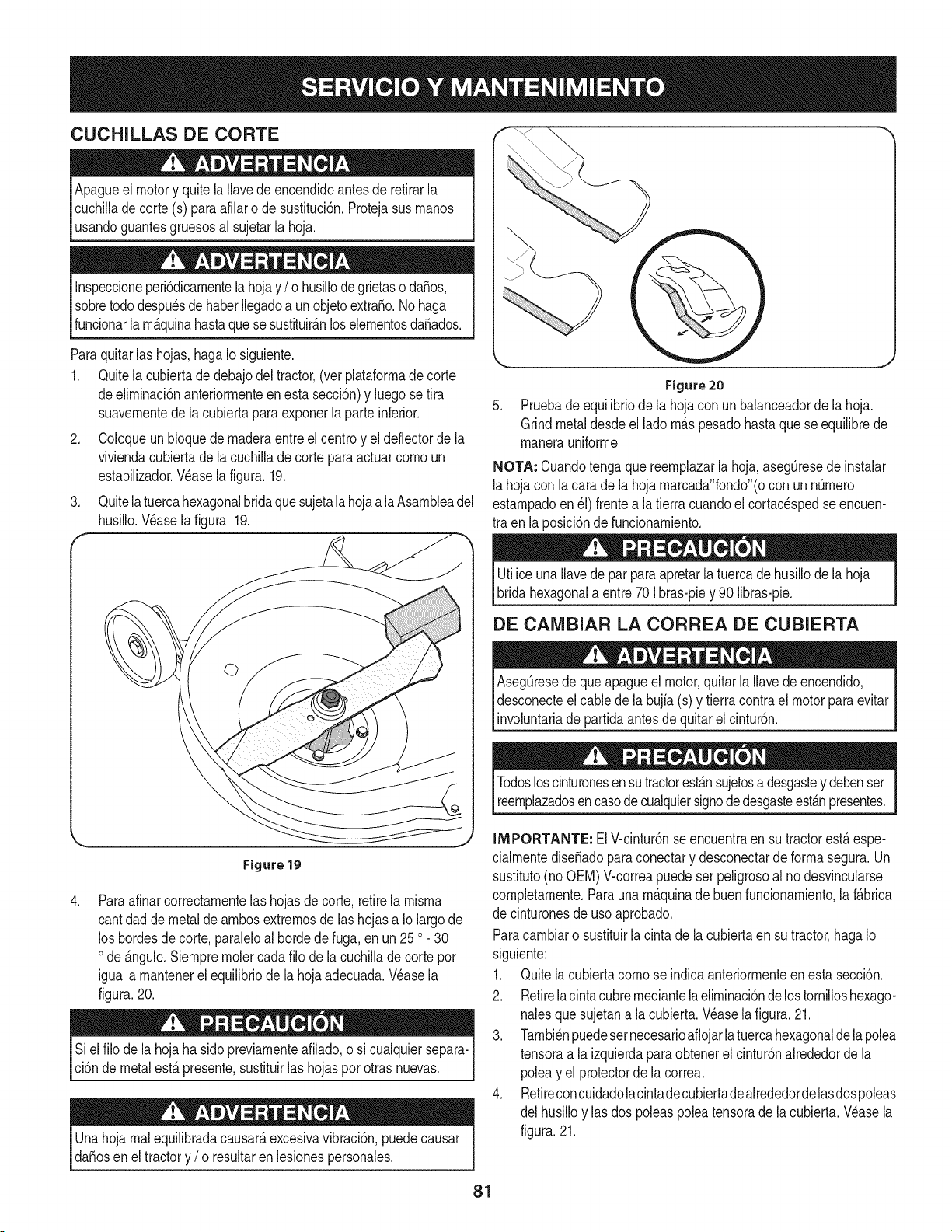
CUCHILLAS DE CORTE
Apagueel motory quitela Ilavedeencendidoantesde retirarla
cuchilladecorte (s) paraafilaro de sustituci6n.Protejasusrnanos
usandoguantesgruesosal sujetarla hoja.
Inspeccioneperi6dicarnentela hojay /o husillode grietaso da_os,
sobretododespu_sdehaberIlegadoa un objetoextra_o.No haga
funcionarla rn_.quinahastaquese sustituir_.nloselernentosda_ados.
Paraquitarlas hojas,hagaIo siguiente.
1. Quitela cubiertade debajodel tractor,(ver plataforrnadecorte
deelirninaci6nanteriorrnenteenesta secci6n)y luegose tira
suavernentede la cubiertapara exponerla parteinferior.
2. Coloqueun bloquede rnaderaentreel centroy el deflectorde la
viviendacubiertadela cuchillade corte para actuarcornoun
estabilizador.Wase lafigura.19.
3. Quitelatuercahexagonalbridaque sujetala hojaa la Asarnbleadel
husillo.Wase la figura.19.
Figure20
Pruebade equilibriode la hojacon unbalanceadorde lahoja.
Grindmetaldesdeel ladorn_.spesadohasta que se equilibrede
rnanerauniforrne.
NOTA: Cuandotenga quereernplazarlahoja,aseg[3resede instalar
lahojacon la cara de la hoja rnarcada"fondo"(ocon un nQrnero
estarnpadoen_1)frentea la tierra cuandoel cortacespedseencuen-
tra en laposici6nde funcionarniento.
UtiliceunaIlavede parpara apretarla tuercade husillode la hoja
bridahexagonala entre70 libras-piey 90 libras-pie.
DE CAIVlBIAR LA CORREA DE CUBIERTA
Aseg_resedeque apagueel motor,quitarla Ilavede encendido,
desconecteel cablede labujfa(s) y tierracontrael motorparaevitar
involuntariadepartidaantesde quitarel cintur6n.
.
Figure 19
Paraafinarcorrectarnentelashojasde corte,retirela rnisrna
cantidadde metalde arnbosextrernosde las hojasa Iolargo de
los hordesde corte,paraleloal horde de fuga, en un 25 o 30
ode _.ngulo.Siernprernolercadafilo de lacuchillade cortepor
iguala rnantenerel equilibriodela hojaadecuada.Wase la
figura.20.
Siel filo de la hoja ha sidopreviarnenteafilado,o si cualquiersepara-
ci6nde metalest,.presente,sustituirlas hojaspor otrasnuevas.
Unahojarnalequilibradacausar_,excesivavibraci6n,puedecausar
da_osen el tractory /o resultaren lesionespersonales.
Todosloscinturonesensutractorest_.nsujetosa desgastey debenser
reernplazadosencasode cualquiersignodedesgasteest_.npresentes.
IMPORTANTE: ElV-cintur6nse encuentraen su tractorest,. espe-
cialrnentedise_adoparaconectary desconectarde forrnasegura.Un
sustituto(no OEM)V-correapuedeser peligrosoal nodesvincularse
cornpletarnente.Parauna rn_.quinade buen funcionarniento,la f_.brica
de cinturonesde usoaprobado.
Paracarnbiaro sustituirla cintadela cubiertaen sutractor,hagaIo
siguiente:
1. Quitela cubiertacornose indicaanteriorrnenteen esta secci6n.
2. Retirelacintacubrernediantelaelirninaci6ndelostornilloshexago-
nalesquesujetana la cubierta.Wase la figura.21.
3. Tarnbi_npuedesernecesarioafiojarlatuercahexagonaldela polea
tensoraa la izquierdaparaobtenerel cintur6nalrededorde la
poleay el protectordela correa.
4. Retireconcuidadolacintadecubiertadealrededordelasdospoleas
del husilloy las dospoleaspoleatensorade lacubierta.Wase la
figura.21.
81
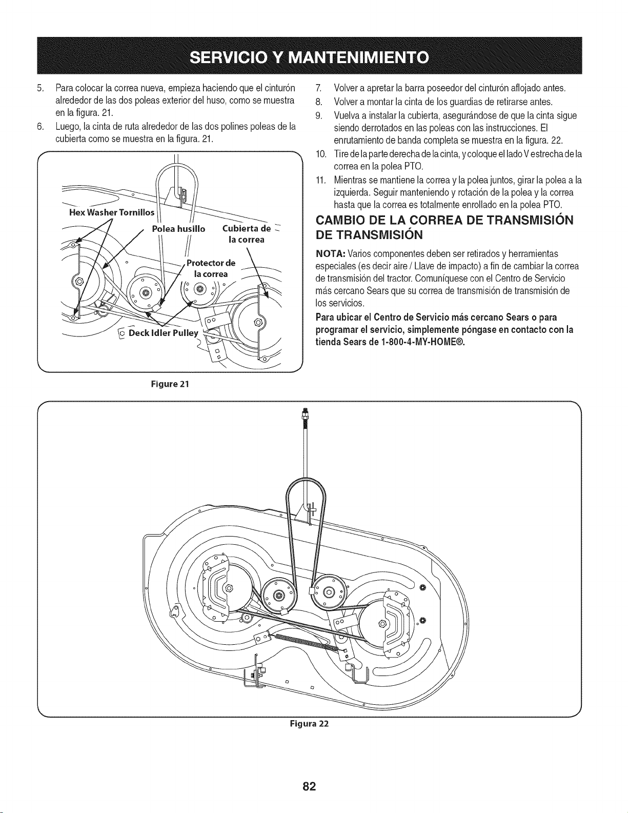
5. Paracolocar la correanueva,empiezahaciendoqueel cintur6n
alrededorde lasdos poleasexteriordel huso,come se muestra
en lafigura.21.
6. Luego,la cinta de rutaalrededorde lasdos polinespoleasde la
cubiertacomese muestraen la figura.21.
Poleahusillo Cubierta de
la cerrea
Protector de
la correa
7. Volvera apretarla barraposeedordel cintur6naflojadoantes.
8. Volvera montarla cinta de losguardiasde retirarseantes.
9. Vuelvaa instalarla cubierta,asegur_.ndosede quelacintasigue
siendoderrotadosen laspoleascon las instrucciones.El
enrutamientodebandacompletase muestraenla figura.22.
10. Tiredelapartederechadelacinta,ycoloqueelladeVestrechadela
correaen lapoleaPTO.
11. Mientrasse mantienela correay la poleajuntos,girar la polea a la
izquierda.Seguirmanteniendoy rotaci6nde la poleay la correa
hastaque la correaes totalmenteenrolladoen la poleaPTO.
CAMBIO DE LA CORREA DE TRANSMISION
DE TRANSMISION
NOTA: Variescornponentesdeben ser retiradosy herramientas
especiales(es deciraire/Llavede impacto)a fin decambiarlacorrea
de transmisi6ndel tractor.Comuniquesecon elCentrede Servicio
m_.scercanoSearsquesu correade transmisi6ndetransmisi6nde
los servicios.
Paraubicar el Centrede Servicio m_scercanoSears o para
programarel servicio,simplementep6ngase en contactocon la
tienda Sears de 1-800-4-MY-HOME®.
Figure 21
I
Figura 22
82
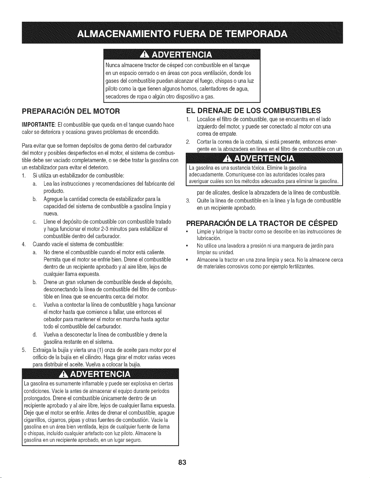
Nuncaalmacenetractorde cespedconcombustibleen el tanque
en unespaciocerradoo en _.reasconpoca venfilaci6n,dondelos
gasesdel combustiblepuedanalcanzarel fuego,chispaso una luz
pilotocomola quetienenalgunoshornos,calentadoresde agua,
secadoresde ropao algQnotto disposifivoa gas.
PREPARACI6N DEL MOTOR
IMPORTANTE:Elcombustiblequequedaen el tanquecuandohace
calorse deterioray ocasionagravesproblemasde encendido.
Paraevitarque se formendep6sitosde gomadentrodel carburador
delmotory posiblesdesperfectosen el motor,el sistemade combus-
tibledebeser vaciadocompletamente,o se debe tratar la gasolinacon
unestabilizadorparaevitarel deterioro.
1. Si ufilizaun estabilizadordecombustible:
a. Lea las instrucdonesy recomendadonesdelfabricantedel
producto.
b. Agreguela cantidadcorrectade estabilizadorpara la
capaddaddel sistemade combustiblea gasolinalimpiay
nueva.
c. Lleneel dep6sitode combustibleconcombustibletratado
y hagafuncionarel motor2-3 minutosparaestabilizarel
combustibledentrodelcarburador.
4. Cuandovacie el sistemade combustible:
a. Nodrene el combustiblecuandoel motorest,.caliente.
Permitaqueel motorse enfrie bien.Dreneel combustible
dentrode un recipienteaprobadoy al airelibre,lejosde
cualquierllamaexpuesta.
b. Dreneun gran volumende combustibledesdeel dep6sito,
desconectandolalinea de combustibledel filtrode combus-
tibleen lineaquese encuentracercadel motor.
c. Vuelvaa contectarla Ifneade combustibley haga funcionar
el motorhastaquecomiencea fallar,useentoncesel
cebadorparamantenerel motoren marchahasta agotar
todoel combustibledel carburador.
d. Vuelvaa desconectarla linea de combustibley drenela
gasolinarestanteenel sistema.
5. Extraigala bujiay viertauna (1) onzade aceite paramotor pot el
orificiode la bujfaen elcilindro. Hagagirar el motorvariasveces
paradistribuirel aceite.Vuelvaa colocarla bujfa.
Lagasolinaessumamenteinflamabley puedesetexplosivaenciertas
condiciones.Vacfela antesde aimacenarei equipoduranteperiodos
prolongados.Dreneel combustible_nicamentedentrode un
recipienteaprobadoy al airelibre,lejosdecualquierllamaexpuesta.
Dejequeel motorseenfrie.Antesde drenarel combustible,apague
cigarrillos,cigarros,pipasy otrasfuentesde combusti6n.Vacfela
gasolinaenuna.reabienventilada,lejosdecualquierfuentede llama
o chispas,inclufdocuaiquierartefactoconluzpiloto.AImacenela
gasolinaenunrecipienteaprobado,en unlugarseguro.
EL DRENAJE DE LOS COMBUSTIBLES
1. Localiceel filtro de combustible,que seencuentraen el lado
izquierdodel motor,y puedeserconectadoal motorcon una
correade empate.
2. Cortarla correade la corbata,si est,.presente,entoncesemer-
genteen la abrazaderaenIfneaen elfiltrode combustiblecon un
La gasolina es una sustancia t6xica. Elimineia gasolina
adecuadamente. Comuniquese con las autoridades locales para
averiguar cua.iesson los metodos adecuados para eliminar la gasolina.
pardealicates,deslicela abrazaderade la Ifneade combustible.
3. Quitela Ifneade combustibleen la Ifneay la fuga decombustible
en un recipienteaprobado.
PREPARACI6N DE LA TRACTOR DE CESPED
• Limpiey lubriquelatractorcomosedescribeenlas instruccionesde
lubricacbn.
• Noutiliceunalavadoraapresi6nni unamanguerade jardfnpara
limpiarsu unidad.
• Almacenelatractoren unazonalimpiay seca.Nola almacenecerca
de materialescorrosivoscomoporejemplofertilizantes.
83
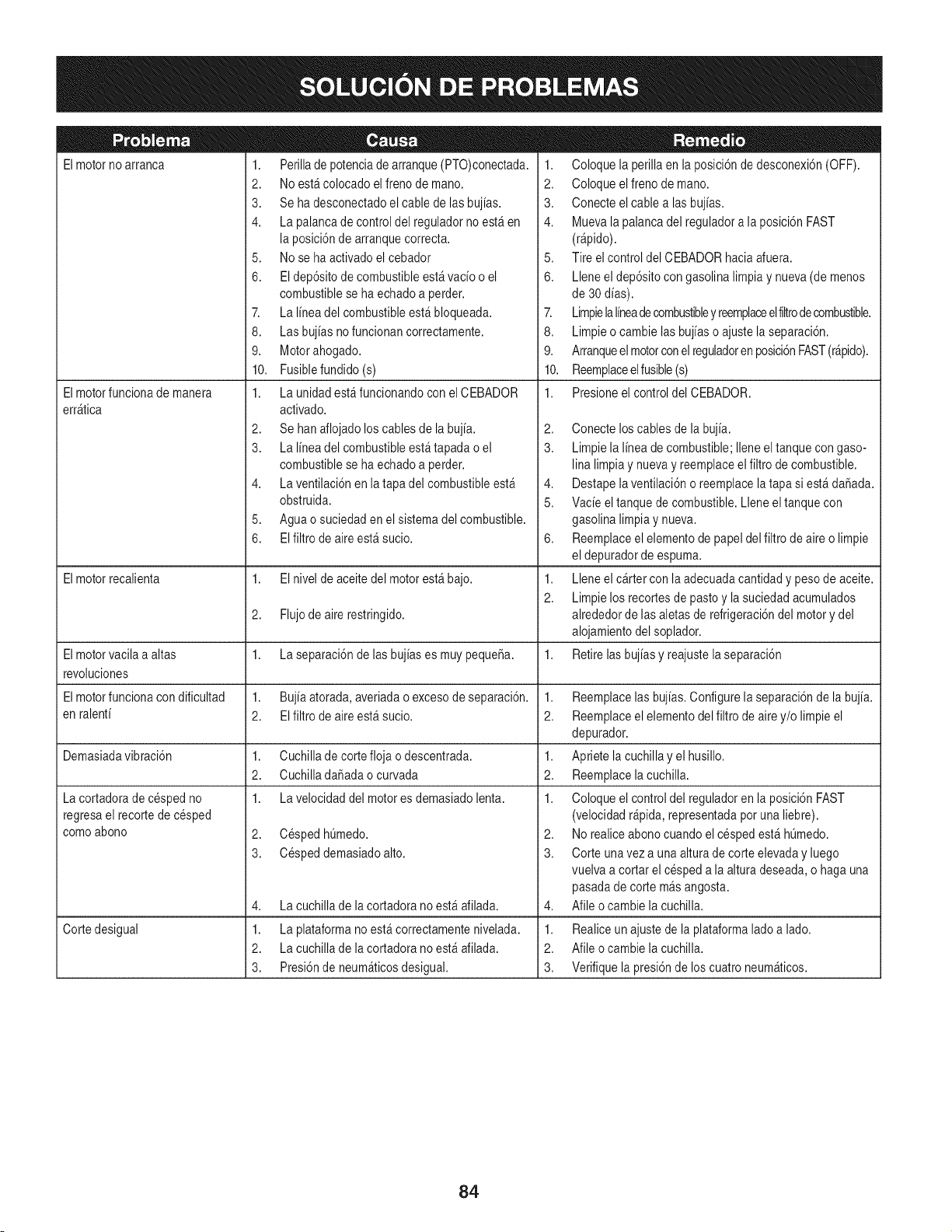
El motorno arranca
Elmotorfuncionade manera
err_tica
1. Perillade potenciade arranque(PTO)conectada.
2. Noest&colocado elfreno de mano.
3. Se ha desconectadoel cable de las bujias.
4. La palancade controldel reguladorno est_ en
la posici6nde arranquecorrecta.
5. Nose ha activadoel cebador
6. El dep6sitode combustibleest_vacio o el
combustiblese haechadoa perder.
7. La linea del combustibleest&bloqueada.
8. Las bujias nofuncionan correctamente.
9. Motorahogado.
10. Fusiblefundido(s)
1. La unidad est_funcionandocon el CEBADOR
activado.
2. Se hanaflojado loscablesde la bujia.
3. La linea del combustibleest_tapada o el
combustiblese haechadoa perder.
4. La ventilaci6nen la tapadel combustibleest_
obstruida.
5. Aguao suciedaden el sistemadel combustible.
6. EIfiltro de aireest_ sucio.
1. Coloque la perillaen la posici6nde desconexi6n(OFF).
2. Coloque elfreno de mano.
3. Conecte elcable alas bujias.
4. Muevala palancadel reguladora la posici6nFAST
(r@ido).
5. Tire el control del CEBADORhacia afuera.
6. Lleneel dep6sitocon gasolina limpiay nueva(de menos
de 30 dias).
7. Limpielalineadecombustibley reemplaceelfiltrodecombustible.
8. Limpieo cambie lasbujias o ajustela separaci6n.
9. Arranqueelmotorconel reguladoren posici6nFAST(r&pido).
10. Reemplaceelfusible(s)
1. Presioneel control del CEBADOR.
2,
3.
4,
5.
6,
El motorrecalienta 1. El nivel de aceite del motorest_ bajo. 1.
2.
2. Flujode aire restringido.
Elmotorvacila a altas 1. La separaci6nde lasbujias es muy pequeSa. 1.
revoluciones
El motorfuncionacon dificultad 1. Bujiaatorada, averiadao excesode separaci6n. 1.
en ralenti 2. El filtrode aireest_ sucio. 2.
Demasiadavibraci6n 1. Cuchillade cortefloja o descentrada. 1.
2. CuchilladaSadaocurvada 2.
1. La velocidaddel motores demasiadolenta. 1.
2. CespedhQmedo.
3. Cespeddemasiadoalto.
La cortadorade cespedno
regresael recortede cesped
comoabono
4,
1.
2.
3.
La cuchillade la cortadora no est_ afilada.
Cortedesigual La plataformano est&correctamentenivelada.
La cuchillade la cortadora no est_ afilada.
Presi6nde neum_ticosdesigual.
Conecte loscablesde la bujia.
Limpiela linea de combustible;Ileneeltanquecon gaso-
lina limpiay nuevay reemplaceelfiltro de combustible.
Destapela ventilaci6no reemplacela tapa si est&daSada.
Vacie el tanquede combustible.Lleneel tanquecon
gasolina limpiay nueva.
Reemplaceelelementode papeldel filtrode aireo limpie
el depuradorde espuma.
Lleneel cartercon la adecuadacantidad y pesode aceite.
Limpielos recortesde pastoy la suciedadacumulados
alrededorde lasaletasde refrigeraci6ndel motory del
alojamientodel soplador.
Retirelas bujias y reajustela separaci6n
Reemplacelas bujias.Configurela separaci6nde la bujia.
Reemplaceelelementodel filtro de airey/o limpie el
depurador.
Apriete lacuchillay el husillo.
Reemplacelacuchilla.
Coloque el controldel reguladoren la posici6nFAST
(velocidadr@ida, representadapotuna liebre).
2. Norealiceabono cuandoel cespedest& hQmedo.
3. Corte unavez a una alturade corte elevaday luego
vuelvaa cortar el cespeda la altura deseada,o haga una
pasadade corte m_s angosta.
4. Afile ocambie la cuchilla.
1. Realiceun ajustede la plataformalado a lado.
2. Afile ocambie la cuchilla.
3. Verifiquela presi6nde los cuatroneum_ticos.
84

This page intentionally left blank. Use this page to make any notes regarding your tractor.
85

86
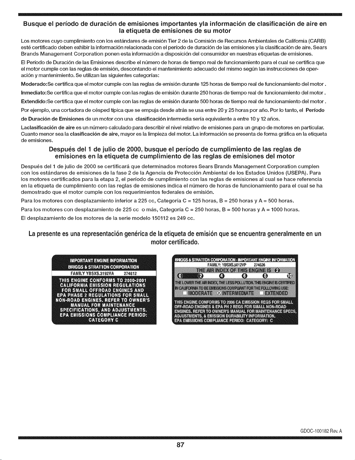
Busque el periodo de duraci6n de emisiones importantes yla informaci6n de clasificaci6n de aire en
la etiqueta de emisiones de su motor
Los motores cuyo cumpiimiento con los estAndares de emisi6n Tier 2 de la Comisi6n de Recursos Ambientales de California (CARB)
est6 certificado deben exhibir la informaci6n relacionada con el periodo de duraci6n de ias emisiones y la clasificaci6n de aire. Sears
Brands Management Corporation ponen esta informaci6n a disposici6n del consumidor en nuestras etiquetas de emisiones.
Ei Periodo de Duraci6n de las Emisiones describe el nQmero de horas de tiempo real de funcionamiento para el cuai se certifica que
el motor cumpie con ias reglas de emisi6n, descontando el mantenimiento adecuado del mismo segQn las instrucciones de oper-
aci6n y mantenimiento. Se utilizan las siguientes categonas:
Moderado:Se certifica que el motor cumpie con las reglas de emisi6n durante 125 horas de tiempo real de funcionamiento del motor.
Inmediato:Se certifica que el motor cumpie con las reglas de emisi6n durante 250 horas de tiempo real de funcionamiento del motor.
Extendido:Se certifica que el motor cumpie con las reglas de emisi6n durante 500 horas de tiempo real de funcionamiento del motor.
Por ejemplo, una cortadora de c6sped tJpica que se empuja desde arras se usa entre 20 y 25 horas por aSo. Por Io tanto, el Periodo
de Duraci6n de Emisiones de un motor con una clasificaci6n intermedia sena equivaiente a entre 10 y 12 aSos.
Laciasificaci6n de aire es un nQmero calculado para describir el nivel relativo de emisiones para un grupo de motores en particular.
Cuanto menor sea la clasificaci6n de aire, mayor es la limpieza del motor. La informaci6n se presenta de forma grAfica en la etiqueta
de emisiones.
Despu_s del 1 de julio de 2000, busque el periodo de cumplimiento de las reglas de
emisiones en la etiqueta de cumplimiento de las reglas de emisiones del motor
Despu6s del 1 de julio de 2000 se certificarA que determinados motores Sears Brands Management Corporation cumplen
con los estAndares de emisiones de la fase 2 de la Agencia de Protecci6n Ambientai de los Estados Unidos (USEPA). Para
los motores certificados para la etapa 2, el periodo de cumplimiento con ias reglas de emisiones al cual se hace referencia
en la etiqueta de cumplimiento con las reglas de emisiones indica el nQmero de horas de funcionamiento para el cual se ha
demostrado que el motor cumple con los requerimientos federales de emisi6n.
Para los motores con desplazamiento inferior a 225 cc, Categoria C = 125 horas, B = 250 horas y A = 500 horas.
Para los motores con desplazamiento de 225 cc o mAs, Categoria C = 250 horas, B = 500 horas y A = 1000 horas.
El desplazamiento de los motores de la serie modelo 150112 es 249 cc.
La presente es una representaci6n gen_rica de la etiqueta de emisi6n que se encuentra generaimente en un
motor certificado.
FAMILYYBSXS.3192VA 274812
GDOC-100182Rev.A
87
(Esta p_.ginase aplica s61oen EE.UU. y Canada.).
Sears Brands Management Corporation, el Consejo de Recursos Ambientales de California (CARB)
y la Agencia de Protecci6n Ambiental de los Estados Unidos (EPA)
Declaraci6n de garantia del sistema de control de emisiones (derechos y obligaciones de la garanfia de defectos del propi=
etario)
LA COBERTURADE LA GARANTJADE CONTROLDE EMISIONESES Y PARALOSMODELOSCERTIFICADOSDELANO 1997Y POSTERIORES,
APLIOABLEA LOS MOTORESCERTIFICADOSCOMPRADOSEN CALIFOR- QUE SE COMPRENY UTILICENEN CUALQUIERPARTEDE LOS ESTADOS
NIA EN1995Y POSTERIORMENTE,QUESE UTILIZANENCALIFORNIA, UNIDOS(Y A PARTIRDEL 1 DE ENERODE 2001 ENCANADA).
Declaraci6n de garanfia sobre defectos en el control de emisiones para California y los Estados Unidos
El Consejode RecursosAmbientalesde California(CARB),la EPA(Agencia
de Protecci6nAmbientalde los EE.UU.)y Searstienenel gusto de explicarla
garantiadel sistemade control de emisionespara motoresdela_o 2000y para
elfuturo con relaci6na motorespeque_ostodo terreno(SORE).En California,
los nuevosmotorespeque_ostodo terrenodebenestar dise_ados,construidos
y equipadosparacumplircon las rigurosasnormasanti-smogdelestado.En
el restode los EstadosUnidos,los motoresnuevostodoterrenode encendido
porchispacertificadosparael a_o 1997debencumplirest_ndaressimilares
establecidospot la EPA.Sears debegarantizarel sistemade control de emis-
iones de su motorpara los periodosde tiempo enumeradosa continuaci6n,
siemprequeno hayaabuso,negligenciao mantenimientoindebidode su
motortodoterrenopeque_o.Su sistemade controlde emisionespuedeincluir
piezastales comoel carburador,el filtro de aire, el sistemade encendido,el
silenciadory el conversorcatalitico.Tambienpuede incluirconectoresy otras
unidadesrelacionadascon lasemisiones.Dondeexistaunacondici6ncubierta
por la garantia,Searsreparar_su peque6omotortodo terrenosin costoalguno
incluyendodiagn6stico,piezasy manode obra
Cobertura de la garantJa Sears para defectos en el control de emJsiones
Los motorestodo terrenopeque6osest_ngarantizadosen Io relativoalcontrol a las disposicionesque se indiquena continuaci6n.Si una partede su motor
de emisionesparadefectosen piezasduranteun periodode dos a_os,sujeto cubiertapot la garanfiaes defectuosa,Sears reparar_o sustituir_dicha parte.
Responsabilidades del propietario en relacibn con la garantia
Comopropietariodel motortodo terrenopeque_o,Ud.es responsablede la
realizaci6ndel mantenimientorequeridoquese incluyeen las instrucciones
de operaci6ny mantenimiento.Searsrecomiendaquese conserventodoslos
recibosrelativosal mantenimientode su motortodoterrenopeque_o,pero
no pude denegarla garantiasimplementepor la faltade los mismos,o por su
incumplimientodel mantenimientoprogramatic.Comopropietariodel motor
peque_otodoterrenodebe saberque, sin embargo,Sears le puedenegar
lacoberturade lagarantiasi su motortodoterrenopeque6oouna piezadel
mismohanfalladodebido a abuso,negligencia,mantenimientoindebidoo
a modificacionesno aprobadas.Ud.es responsablede presentarsu motor
todoterrenopeque6oa un distribuidorde serviciosSearsautorizadotan pronto
comoaparezcaun problema.Las reparacionesde la garantiasin confiicto
debencompletarseen un plazode tiempo razonable,no superiora 30 dias.Si
tienealguna preguntarespectoa sus derechosy responsabilidadesreferen-
tes a la garantia,debe contactarcon un representantede serviciosSearsal
1--800--469--4663.La garantiade emisioneses unagarantiapor defectos.Los
defectosse juzgande acuerdocon elfuncionamientonormalde un motor.La
garantiano est_ relacionadacon unapruebade emisionesen uso.
Disposiciones de la garantJa Sears para defectos en el control de emJsiones
Las siguientesson disposicionesespecificasrelacionadascon la coberturade lagarantia paradefectosen el controlde emisiones.Esun a_adidoa lagarantiade
motorSearspara motoresno reguladosque seencuentraen lasinstruccionesde funcionamientoy mantenimiento.
1. Piezascon garantia
La coberturade esta garantiase extiendeL]nicamentealas piezas
queaparecen a continuaci6n(las partesde los sistemasde control de
emisiones),siempreque dichas piezasestuvieranya en el motoren el
momentode su compra.
a. Sistemade medici6n de combustible
•Sistema de enriquecimientopara arranqueen frio
•Carburadory partesinternas
•Bombade combustible
b. Sistemade inducci6nde aire
•Filtrode aire
•Colector de admisi6n
c. Sistemadeencendido
•Bujia(s) de encendido
•Sistema de encendidomagneto
d. Sistemadelcatalizador
•Convertidorcatalitico
•Colector de escape
•Sistema de inyecci6nde aireo v_lvulade impulsos
e. Elementosvariados usadosen lossistemasanteriores
•Wlvulas de vacio,sensiblesa temperatura,posici6ny tiempo
e interruptores
• Conectoresy montajes
2. AIcancede la cobertura
Searsgarantizaal poseedorinicialy a loscompradoressubsiguientes
quelas piezas con garantiano tendr_n defectosen materialesni mano
de obra que provoquenla falla de las mismasduranteun periodode
dos aSosa partirde la fechaen queel motorse entregaa un comprador
particular.
3. Sin cargo
La reparaci6no reemplazode cualquierpartecon garantia se realizar_
sin cargo alguno parael poseedor,incluyendotareas de diagn6sticoque
permitan determinarsi una parte con garantiaes defectuosa,siempreque
dicho diagn6sticose realiceen un distribuidorde servicios Searsautoriza-
do. Parael servicio de la garantia de emisiones,contacteal distribuidorde
serviciosSearsautorizadom_s cercanoincluidoen las"P_ginasamarillas"
en las categorias"Motores,gasolina","Motoresde gasolina","Podadoras
de cesped",o similares.
4. Reclamacionesy exclusionesa la cobertura
Las reclamacionesde lagarantia debenenviarsede acuerdocon las
disposicionesde la politica de garantia para motoresSears. La cobertura
de lagarantia excluir_defectosen piezascon garantia queno scan partes
originalesSears,o abuso,negligenciao mantenimientoincorrecto,tal y
como se estableceen lapolitica de garantia para motoresSears.Sears no
es responsablede lasfallas en piezas con garantia provocadaspor el uso
de partes a6adidas,que no scan originaleso quese hayan modificado.
5. Mantenimiento
Cualquierpartecon garantiaque no este programadaparaser reem-
plazadacomomantenimientorequerido,o que s61odebainspeccionarse
regularmentealefecto de "inspeccioneo reemplacesegL]nsea necesario",
estar_garantizadacontradefectosduranteel periodode la garantia.Todas
las piezasgarantizadasque esten programadaspara su reemplazopara
cumplir con los requisitosde mantenimientoestar_ngarantizadass61o
por el periodoanterioral primerreemplazoprogramaticparadicha pieza.
Cualquierpiezade recambioquesea equivalenteen funcionamientoy
durabilidadpuedeusarse para realizar mantenimientoo reparaciones.El
propietarioes responsablede realizartodoel mantenimientorequerido,tal
y comose define en las instruccionesde funcionamientoy mantenimiento
Sears
6. Coberturaindirecta
Porla presente,la coberturase extiendea la falla de cualquiercomponente
de motorprovocadapot lafalla de unapieza con garantiaque estetodavia
en periodode garantia.
En los EstadosUnidosy Canad_hay unalinea de atenci6nde 24 horas,1-800-469--4GG3,quecuentacon un menL]con mensajespre-grabadosque contienen
informaci6npara el mantenimientode motores.
DECLARACIONFEDERALy/oDECALIFORNIASOBRE GARANTJAS EN EL CONTROL DE EIVIISIONES
SUS DERECHOS Y OBLIGACIONES EN CUANTO A LA GARANTJA
MTDConsumerGroupInc, la Agencia de Protecci6nMedioambientalde los EstadosUnidos(EPA),y para aquellosproductoscertificadosparasu ventaen el es-
tadode California,el Departamentode los Recursosdel Aire deCalifornia(CARB)secomplacenenexplicarla garanfiaque cubre al sistemade control (ECS)de
emisiones(evaporativasy/o de escape)de su equipoy motor(motor de equiposde exteriores)de encendidopot chispa paratodo terreno,peque_o,de exteriores
del a_o 2006 y a_osposterioresEn California,los nuevosmotoresde equipos de exterioresdebenestar dise_ados,construidosy equipadospara cumplircon las
estrictasnormasantipoluci6ndel Estado(en otrosestados,losequipos del a_o 1997y modelosposterioresdebenser estar dise_ados,construidosy equipados
para cumplircon las regulacionesde motoresde encendidopor chispa paratodoterrenopeque_osde la Agencia de Protecci6nMedioambientalde los Estados
Unidos, (EPA).MTD ConsumerGroupInc. debe garantizarel sistemade control de emisiones(ECS) de su motorde equipos de exteriorespot el periodode
tiempo indicadom_s abajo,siemprey cuando no existauso incorrecto,negligenciao mantenimientoinadecuadode dicho motor.
Su ECSpuede incluir piezastales como el carburador,el sistemade inyecci6nde combustible,el sistemade encendido,el convertidorcatalitico,losdep6sitos
de combustible,las lineas de combustible,lostaponesde combustible,lasv_lvulas, contenedores,filtros, manguerasde vapor,abrazaderas,conectoresyotros
componentesafinesrelacionadoscon lasemisiones.
Dondeexista unacondici6ncubiertapor la garantia, MTDConsumerGroupInc. reparar_su motorde equiposde exterioressincosto algunoincluyendoel
diagn6stico,las piezasy la mano de obra.
COBERTURA DE LA GARANTJA DEL FABRICANTE:
Este sistemade controlde emisionesse garantizaporel t@minode dos aSos.Si alguna piezarelacionadacon las emisionesde su motorde equiposde
exterioreses defectuosa,MTDCONSUMERGROUPINC. reparar_o sustituir_dichapieza.
RESPONSABILIDADES DEL PROPIETARIO SEGUN LA GARANTJA:
En su car_cterde propietariodel motorde equipos de exteriores,usted es responsabledel mantenimientorequeridoquese especificaen el manualdel propieta-
rio.MTDConsumerGroupInc le recomiendaque conservetodos losrecibos quecubrenel mantenimientode su motor,no obstanteIo cual MTDConsumerGroup
Inc no podr_denegarel cumplimientode lagarantia Qnicamentepor lafaltade los recibos.
Comopropietariodel motorde equiposde exteriores,usteddebe saber queMTDConsumerGroup Inc. puededenegarlacoberturade lagarantia si su motoro
unapieza del mismofallandebido a uso incorrecto,negligencia,mantenimientoindebido o a modificacionesno aprobadas.
Ustedes responsablede presentarsu motoral centro de distribuci6no serviciotecnico de MTD ConsumerGroupInc. tan prontocomo aparezcael problema.Las
reparacionescubiertaspor la garantiase debenIlevara caboen un lapsorazonableque no excedade 30 dias. Si tiene alguna preguntarespectode lacobertura
de la garantia, p6ngaseen contactocon el Departamentodel ServicioT@nicode MTD ConsumerGroup Inc. al telefono1-800-800-7310o pot correoelectr6nico
en http://support.mtdproducts.com
COBERTURA DE LA GARANTJA DE EMISIONES GENERALES:
MTDConsumerGroupIncgarantizaal compradorfinal y a cadacompradorsubsiguienteque el motorde equiposde exteriores:est_ dise_ado,construidoy
equipadode modo de cumplir contodas las regulacionesaplicablesy quese encuentralibre de defectosde materialesyde fabricaci6nque pudierencausarla
falla de una piezagarantizadaidentica,en todos losaspectos materialesa la pieza descriptaen la solicitudde certificaci6nde MTDConsumerGroup Inc.
El periodode garantiacomienzaen la fechade entregadel motoral compradorfinal o en lafecha en que la m_quinase pone en funcionamientopot primeravez.
El periodode garantiaes de dos aSos.
Sujetoa ciertas condicionesy exclusionesquese indicana continuaci6n,lagarantia de las piezasrelacionadascon lasemisioneses la siguiente:
1. Cualquierpiezagarantizadaque no este programadapara ser reemplazadacomo parte del mantenimientorequeridoen las instruccionesescritassuminis-
tradasse garantizaporel periodo de garantiaarriba mencionado.Si la pieza falla duranteel periodo de coberturade lagarantia,la mismaser_ reparada
o reemplazadapor MTDConsumerGroupInc. de acuerdo con el parrafo(4) a continuaci6n.Cualquierpiezareparadao reemplazadasegQnla garanfia se
garantizar_potel resto del periodode garantia.
2. Cualquierpiezagarantizadaque este programadasolamentepara inspecci6nregularen las instruccionesescritassuministradassegarantiza pot el periodo
de garantia arribamencionado.Cualquierpiezareparadao reemplazadasegQnla garantiase garantizar_pot el restodel periodo.
3. Cualquierpiezagarantizadaqueeste programadapara reemplazosegQnel mantenimientorequeridode conformidadcon lasinstruccionesescritassuminis-
tradas,se garantizaporel periodode tiempo anteriora la primerafecha de reemplazoprogramadapara esa pieza. Si la piezafalla antes del primerreemplazo
programatic,la mismaser&reparadao reemplazadapot MTDConsumerGroup Inc. de acuerdo con el parrafo(4) a continuaci6n.Cualquier piezareparadao
reemplazadabajogarantia se garantizar_pot el resto del periodoanterioral primerreemplazoprogramatic puntualpara esa pieza.
4. La reparaci6no el reemplazode cualquierpieza garantizadade conformidadcon las disposicionesde la garantia queaqui se estipulase deben realizaren un
centrode garantiasin costo alguno para el propietario.
5. Noobstantelas disposicionesque aquise estipulan,los servicioso reparacionesbajo garantiase suministrar_nen todos nuestroscentros de distribuci6nbajo
franquiciade mantenimientopara los motoreso equiposen cuesti6n.
6. El propietariodel motorde equiposde exterioresno deber_pagarel trabajode diagn6sticodirectamenteasociadocon unapiezagarantizadadefectuosaen
relaci6ncon las emisiones,siemprey cuandodicho trabajode diagn6sticose realiceen un centrocubiertopot la garantia.
7. MTDConsumerGroup Inces responsablepotdaSoscausadosa otros componentesde motoreso equipos derivadosde lafalla bajo garantiade cualquier
piezagarantizada.
8. Durantelatotalidaddelperiododegarantiadelmotoryequipoparatodoterrenoarribamencionado,MTDConsumerGroupIncmantendr_unsuministro
depiezasbajogarantiasuficienteparasatisfacerlademandaesperadadetalespiezas.
9. Cualquierpiezadereemplazosepodr_usarparaelcumplimientodelmantenimientoolasreparacionesbajogarantiaysesuministrar_nsincargopara
elpropietario.Dichousonoreducir_lasobligacionesdegarantiadeMTDConsumerGroupInc.
10.Nosepodr_nusarpiezasadicionalesnimodificadasquenoestenexentasdeacuerdoconelDepartamentodelosRecursosdelAire(AirResourcesBoard).
Elusodecualquierpiezaadicionalomodificadanoexentaporelcompradorfinalser_causaldeinvalidezdelosreclamosbajogaranfia.MTDConsumer
GroupIncnotendr_responsabilidadpotlagarantiadefallasdepiezasgarantizadasquefuerencausadaspotelusodeunapiezaadicionalnoexenta
omodificada.
PIEZAS GARANTIZADAS:
La reparaci6no el reemplazode cualquierpieza garantizadaquede otto modo pudieseestar cubiertapor lagarantia podr_set excluidade tal coberturade
garantiasi MTDConsumerGroup Incdemuestraqueel motores objeto de uso incorrecto,negligenciao mantenimientoinadecuado,y que tal uso incorrecto,
negligenciao mantenimientoinadecuadofue causa directade la necesidadde reparaci6no reemplazode dicha pieza.NoobstanteIo antedicho,cualquierajuste
de un componentecon un dispositivode limitaci6nde ajusteinstaladoen f_brica y que funcioneadecuadamente,podr_set cubiertopot la garantia.Adem_s,
la coberturabajoestagarantiase extiendesolo a piezasqueestuvieronpresentesen el motory equipotodo terrenoadquiridos.
Est_ncubiertaslas siguientespiezascon garanfia para emisiones(decorresponder):
(1) Sistemade medici6nde combustible
• Sistemade mejorapara inicio en frio (cebadosuave)
• Carburadory piezasinternas(o sistemade inyecci6npotcombustible)
• Bomba de combustible
• Dep6sitode combustible
(2) Sistemade inducci6nde aire
• Purificadordeaire
• Colectordeadmisi6n
(3) Sistemade encendido
• Bujia(s) deencendido
• Sistemade encendidopot magneto
(4) Sistemade encendido
• Convertidorcatalitico
,, SAI (v_lvula Reed)
(5) Componentesvariosutilizadosen el sistemaanterior
• Wlvulas e interruptoresde vacio,temperatura,posici6nsensiblesal tiempo
• Conectoresy montajes
(6) Controlevaporativo
• Manguerade combustible
• Abrazaderasde la manguerade combustible
• Tap6ndel combustibleatadopot correa
• Cajadecarbono
• Lineas de vapor
GDOC-100223

Felicitaciones por haber realizado una adquisici6n inteligente. El producto Craftsman® que ha
adquirido esta diseSado y fabricado para brindar muchos aSos de funcionamiento confiable. Pero
como todos los productos a veces puede requerir de reparaciones. Es en ese momento cuando el
disponer de un Acuerdo de protecci6n para reparaciones le puede ahorrar dinero y problemas.
A continuaci6n se detallan los puntos incluidos en el Acuerdo:
[] Servicio experto prestado por nuestros 10,000 especialistas en reparaciones profesionales
[] Servicio ilirnitado sin cargo para las piezasy la mano de obra en todas las reparacionescubiertas
[] Reernplazo del producto hasta 1500 d61aressi no es posible reparar el producto cubierto
[] Descuento de 25% del precio normal del servicio y de las piezas relacionadas con el mismo que no esten cubiertas
por el acuerdo; ademas, 25% del precio normal de laverificaci6n de mantenimientopreventivo
[] Ayuda r_pida pot tel_fono - Io IlamamosResoluci6n RApida- el apoyo telef6nico de un Chamusca al representante.
Piense en nosotros como el manual "de un dueSo hablador."
Una vez adquirido el Acuerdo, puede programar el servicio con tan s61orealizar una Ilamadatelef6nica. Puede Ilamaren
cualquier momento del dia o de la noche o programar un servicio en linea.
ElAcuerdo de Protecci6nde Reparaci6nes una compra sin riesgo. Si usted anula por alguna raz6n durante el periodo de
garantia de producto, proporcionaremos un reembolso Ileno.O, un reembolso prorrateado en cualquier momento despues
del periodo de garantia de producto expira, iAdquiera hoy su acuerdode protecci6n para reparaciones!
Se aplican determinadas limitaciones y exclusiones. Para obtener informaciTn adicional y precios en los Estados
Unidos Ilame al 1-800-827-6655.
El *Coverage en Canad_ivaria en algunos articulos. Para detalles Ilenos la Ilamada Chamusca Canad_ien 1-800-
361-8885.
Servicio de instalaci6n de Sears
Si desea solicitar la instalaci6n profesionalde Sears de aparatosdomesticos, dispositivos paraabrir portones, calentado-
res de agua y otros articulos domesticos importantes, en los Estados Unidos o Canada flame al 1-800-4-MY-HOME®.
91

Riding Equipment
questions or problems?
Satisfaction with your purchase
is our number one concern!
To troubleshoot problems,
get answers to questions, order parts,
or schedule repair service for your
Riding Equipment, call the number below.
Para respuestas a preguntas o problemas,
y ordenar piezas o pedir servicio para la
reparacibn de su equipo, Ilame el nt_mero abajo.
1-800-659-5917
Craftsman Help Line
www.craftsman.com
TM
® Registered Trademark /Trademark of KCD IP, LLC in the United States, or Sears Brands, LLC in other countries
® Marca Registrada /TMMarca de Fabrica de KCD IP, LLC en Estados Unidos, o Sears Brands, LLC in otros paises