perator's
I:RnFrSMRN°
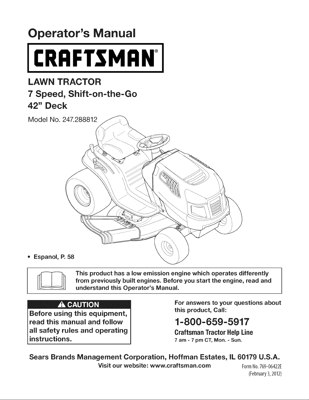
LAWN TRACTOR
7 Speed, Shift-on=the=Go
42" Deck
Model No. 247.288812
• Espanol, P. 58
This product has a low emission engine which operates differently
from previously built engines. Before you start the engine, read and
understand this Operator's Manual.
Before using this equipment,
read this manual and follow
all safety rules and operating
instructions.
For answers to your questions about
this product, Call:
1-800=659=5917
Craftsman Tractor Help Line
7 am = 7 pm CT, Mort. =Sun.
Sears Brands Management Corporation, Hoffman Estates, IL 60179 U.S.A.
Visit our website: www.craftsman.com FormNo.769-06422E
(February3,2012)
Warranty Statement .......................................................... 2
Safety Instructions ............................................................ 3
Slope Gauge ..................................................................... 8
Assembly ........................................................................... 9
Operation ........................................................................ 11
Service and Maintenance .............................................. 17
Off-Season Storage ........................................................ 26
Trou bleshooting .............................................................. 27
Labels ............................................................................. 28
Parts List ......................................................................... 30
Espa_ol ............................................................................ 58
Service Numbers ............................................. Back Cover
CRAFTSMAN FULL WARRANTY
FORTWOYEARSfromthe dateof purchase,all non-expendablepartsof this ridingequipmentarewarrantedagainstanydefectsin material
orworkmanship.A defectivenon-expendablepartwill receivefreein-homerepairor replacementif repairis impossible.
FORFIVEYEARSfromthe dateof purchase,the frameof this ridingequipmentis warrantedagainstany defectsin materialor workmanship.
A defectiveframewill receivefree in-homerepairor replacementif repairis impossible.
FORTENYEARSfromthe dateof purchase,thefrontaxle of thisridingequipmentis warrantedagainstany defectsin materialor workman-
ship.A defectivefrontaxle will receivefree in-homerepairorreplacementif repairis impossible.
FOR90 DAYSfromthe dateof purchase,the battery(anexpendablepart)of thisridingequipmentis warrantedagainstanydefects in material
orworkmanship(ourtestingprovesthatit will not holda charge). A defectivebatterywill receivefree in-homereplacement.
ADDiTiONAL LiFETiMELiMiTEDWARRANTYon CAST iRONFRONTAXLE(if equipped)
FORAS LONGAS ITIS USEDby theoriginalownerafterthe tenthyearfrom the dateof purchase,thecast ironfrontaxle(if equipped)of
this ridingequipmentiswarrantedagainstanydefectsinmaterialor workmanship.Withproofof purchase,a defectivecastironfrontaxlewill
receivefreein-homereplacement.
WARRANTYSERVICE
Forwarrantycoveragedetailsto obtainfreerepairor replacement,call 1-800-659-5917or visitthe website: www.craftsman.corn
In all casesabove,if part repairor replacementisimpossible,the ridingequipmentwill be replacedfreeof chargewiththe sameor an
equivalentmodel.
Allof theabovewarrantycoverageisvoidifthisridingequipmentiseverusedwhileprovidingcommercialservicesorif rentedto anotherperson.
This warrantycovers ONLYdefects in materialandworkmanship. Warranty coverage does NOTinclude:
• Expendableparts(exceptbattery)that canwearout fromnormalusewithinthe warrantyperiod,includingbut not limitedto blades,
sparkplugs,aircleaners,belts,andoil filters.
• Standardmaintenanceservicing,oilchanges,or tune-ups.
• Tire replacementor repaircausedby puncturesfrom outsideobjects,such as nails,thorns,stumps,or glass.
• Tireor wheelreplacementor repairresultingfromnormalwear,accident,orimproperoperationor maintenance.
• Repairsnecessarybecauseof operatorabuse, includingbut notlimitedto damagecausedby towingobjectsbeyondthe capabilityof
the ridingequipment,impactingobjectsthat bend theframe,axle assemblyorcrankshaft,or over-speedingthe engine.
• Repairsnecessarybecauseof operatornegligence,includingbut not limitedto,electricaland mechanicaldamagecausedby
improperstorage,failureto usethe propergradeandamountof engineoil, failureto keepthe deckclearof flammabledebris,or
failureto maintainthe ridingequipmentaccordingto the instructionscontainedinthe operator'smanual.
• Engine(fuel system)cleaningor repairscausedbyfuel determinedto be contaminatedor oxidized(stale).In general,fuel shouldbe
usedwithin30 daysof itspurchasedate.
• Normaldeteriorationandwearof the exteriorfinishes,or productlabelreplacement.
Thiswarrantygivesyou specificlegal rights,andyoumayalsohaveother rightswhichvaryfrom stateto state.
Sears Brands ManagementCorporation, Hoffman Estates, IL 60179
EngineOil: SAE30
Fuel: UnleadedGasoline
SparkPlug: Champion®RC12YC
Engine: Briggs& StrattonI/C®
ModelNumber:
Serial Number:
Dateof Purchase:
Recordthe modelnumber,serialnumber,
anddateof purchaseabove.
© KCD IR LLC 2
Thissymbolpointsout importantsafetyinstructionswhich,if not
followed,couldendangerthepersonalsafetyand/orpropertyof
yourselfandothers. Readandfollowall instructionsin thismanual
beforeattemptingto operatethismachine.Failureto complywith
theseinstructionsmayresultin personalinjury.Whenyou seethis
symbol,HEEDITSWARNING!
CALIFORNIA PROPOSITION 65
EngineExhaust,someof itsconstituents,andcertainvehicle
componentscontainoremitchemicalsknownto Stateof California
to cause cancerand birthdefectsor other reproductiveharm.
Batteryposts,terminals,and relatedaccessoriescontainlead and
leadcompounds,chemicalsknownto the Stateof Californiato
causecancerand reproductiveharm.Washhandsafter handling.
Thismachinewasbuiltto be operatedaccordingto the safeopera-
tion practicesin this manual.As with anytypeof powerequipment,
carelessnessorerroron the partof the operatorcan resultin serious
injury.Thismachineis capableof amputatingfingers,hands,toes
andfeet and throwingdebris.Failureto observethe followingsafety
instructionscouldresultin seriousinjuryor death.
Your Responsibility--Restrict the useof thispowermachineto
personswho read,understandand follow thewarningsand instruc-
tionsin this manualand on the machine.
SAVE THESE INSTRUCTIONS!
GENERAL OPERATION
• Read,understand,andfollowall instructionson the machineand
in themanual(s)beforeattemptingto assembleand operate.
Keepthis manualina safe placefor futureand regularreference
andfor orderingreplacementparts.
• Befamiliarwithall controlsandtheir properoperation.Knowhow
to stop the machineanddisengagethemquickly.
• Neverallowchildrenunder 14 yearsold to operatethis machine.
Children14yearsoldand over shouldreadand understandthe
operationinstructionsandsafetyrulesin this manualandshould
betrainedandsupervisedbya parent.
• Neverallowadultsto operatethis machinewithoutproper
instruction.
• Tohelpavoidbladecontactor a thrownobjectinjury,keep
bystanders,helpers,childrenandpetsat least 75 feet fromthe
machinewhile it is in operation.Stopmachineif anyoneenters
the area.
• Thoroughlyinspectthe areawherethe equipmentis to be used.
Removeallstones,sticks,wire,bones,toys,and otherforeign
objectswhichcouldbe pickedupand thrownby the blade(s).
Thrownobjectscan causeseriouspersonalinjury.
• Planyour mowingpatternto avoiddischargeof materialtoward
roads,sidewalks,bystandersandthe like.Also,avoiddischarg-
ingmaterialagainstawall orobstructionwhichmaycause
dischargedmaterialto ricochetback towardthe operator.
• Alwayswear safetyglassesor safetygogglesduring operation
andwhile performingan adjustmentor repairto protectyoureyes.
Thrownobjectswhich ricochetcancauseseriousinjuryto the
eyes.
• Wearsturdy,rough-soledworkshoesandclose-fittingslacksand
shirts.Loosefittingclothesandjewelry canbe caughtin movable
parts.Neveroperatethis machinein bare feet or sandals.
• Beawareof the mowerandattachmentdischargedirectionand
do not pointit at anyone.Donot operatethe mowerwithoutthe
dischargecoverorentiregrasscatcherin its properplace.
Donot put handsor feet near rotatingpartsor underthe cutting
deck. Contactwiththe blade(s)can amputatehandsandfeet.
A missingor damageddischargecovercan causebladecontact
or thrownobjectinjuries.
• Stoptheblade(s)whencrossinggraveldrives,walks,or roads
andwhile notcuttinggrass.
• Watchfor trafficwhenoperatingnear or crossingroadways.This
machineis not intendedfor useon any public roadway.
• Donot operatethe machinewhile underthe influenceof alcohol
or drugs.
• Mowonly in daylightor good artificiallight.
Nevercarrypassengers.
• Disengageblade(s)beforeshiftinginto reverse.Backup slowly.
Alwayslookdownandbehindbeforeandwhile backingto avoida
back-overaccident.
3
• Slowdownbeforeturning.Operatethe machinesmoothly.Avoid
erraticoperationandexcessivespeed.
Disengageblade(s),setparkingbrake,stopengineandwaituntil
the blade(s)come to a completestopbeforeremovinggrass
catcher,emptyinggrass,uncloggingchute,removinganygrass or
debris,or makinganyadjustments.
Neverleavea runningmachineunattended.Alwaysturnoff
blade(s),setparkingbrake,stopengineand removekeybefore
dismounting.
Useextracare whenloadingorunloadingthe machineintoa
traileror truck. This machineshouldnot bedrivenupor down
ramp(s),becausethe machinecouldtip over,causingserious
personalinjury.The machinemustbe pushedmanuallyon
ramp(s)to loador unloadproperly.
Mufflerandenginebecomehotandcan causea burn.Do not
touch.
Checkoverheadclearancescarefullybeforedrivingunderlow
hangingtree branches,wires,dooropeningsetc.,wherethe
operatormaybe struckor pulledfrom the machine,whichcould
resultinseriousinjury.
Disengageallattachmentclutchesanddepressthe brakepedal
completelybeforeattemptingto start engine.
Yourmachineisdesignedto cut normalresidentialgrass of a
heightno morethan 10".Do not attemptto mowthroughunusually
tall,dry grass (e.g.,pasture)or piles of dry leaves.Drygrassor
leavesmaycontactthe engineexhaustand/or buildup on the
mowerdeckpresentinga potentialfire hazard.
Useonlyaccessoriesand attachmentsapprovedfor this machine
by the machinemanufacturer.Read,understandand followall
instructionsprovidedwiththe approvedaccessoryor attachment.
Fora list of approvedaccessoriesandattachments,call 1-800-
659-5917.
Dataindicatesthatoperators,age60years and above,are
involvedin a largepercentageof riding mower-relatedinjuries.
Theseoperatorsshouldevaluatetheirabilityto operatethe riding
mowersafelyenoughto protectthemselvesandothersfrom
seriousinjury.
If situationsoccurwhicharenot coveredinthis manual,usecare
andgoodjudgment.Contact1-800-659-5917for informationand
assistance.
SLOPE OPERATION
Slopesare a majorfactorrelatedto lossof controlandtip-over
accidentswhichcan result in severeinjuryor death.All slopes require
extracaution.Ifyoucannotback up the slopeor if youfeel uneasyon
it, do not mowit.
Foryoursafety,use the SlopeGuideincludedas partof this manual
to measureslopesbeforeoperatingthis machineona slopedor hilly
area. If the slopeis greaterthan15degreesas shownonthe Slope
Guide,do notoperatethis machineonthatareaor seriousinjurycould
result.
Do:
o
Mowupand down slopes,not across.Exerciseextremecaution
whenchangingdirectionon slopes.
• Watchfor holes,ruts,bumps,rocks,orother hiddenobjects.
Uneventerraincouldoverturnthe machine.Tallgrass can hide
obstacles.
Useslowspeed.Choosea lowenoughspeedsettingso that
you will nothaveto stop or shiftwhileon the slope.Tires may
lose tractionon slopeseventhoughthe brakesarefunctioning
properly.Alwayskeepmachinein gearwhen goingdownslopes
to take advantageof enginebrakingaction.
• Followthe manufacturer'srecommendationsfor wheelweights
or counterweightsto improvestability.Forrecommendations,call
1-800-659-5917.
• Useextracarewith grass catchersor otherattachments.These
can changethe stabilityof the machine.
Keepallmovementonthe slopesslowand gradual.Do not make
suddenchangesin speedor direction.Rapidengagementor
brakingcouldcausethe frontof the machineto lift and rapidlyflip
overbackwardswhichcouldcauseseriousinjury.
• Avoidstartingorstoppingona slope. If tires losetraction,disen-
gagethe blade(s)and proceedslowlystraightdownthe slope.
DoNot:
• Donot turnon slopesunlessnecessary;then, turnslowlyand
graduallydownhill,if possible.
• Donot mowneardrop-offs,ditchesor embankments.The mower
could suddenlyturnover if a wheelis overthe edgeof a cliff,
ditch,or if an edgecavesin.
• Donot try to stabilizethe machineby puttingyourfooton the
ground.
• Donot usea grass catcheron steepslopes.
• Donot mowon wetgrass.Reducedtractioncouldcausesliding.
• Donot attemptto coastdownhill.Over-speedingmaycausethe
operatorto lose controlof the machineresultingin seriousinjury
or death.
• Donot towheavypull behindattachments(e.g. loadeddumpcart,
lawn roller,etc.)on slopesgreaterthan5 degrees.Whengoing
down hill,the extraweighttendsto pushthe tractorandmay
causeyou to loosecontrol(e.g. tractormayspeedup, brakingand
steeringabilityare reduced,attachmentmayjack-knifeandcause
tractorto overturn).
4
CHILDREN
Tragicaccidentscanoccurifthe operatoris notalert to the presence
of children.Childrenare often attractedto the machineandthe mowing
activity.Theydo notunderstandthe dangers.Neverassumethat
childrenwill remainwhereyou last sawthem.
• Keepchildrenout of the mowingareaand inwatchfulcare of a
responsibleadultotherthanthe operator.
• Bealert andturnmachineoff ifa childentersthe area.
• Beforeandwhilebacking,lookbehindand downfor small
children.
Nevercarrychildren,evenwiththe blade(s)shutoff.Theymay
fall off and be seriouslyinjuredor interferewithsafemachine
operation.
• Useextremecarewhenapproachingblindcorners,doorways,
shrubs,treesor otherobjectsthat may block yourvisionof a child
whomay run intothe machine.
Toavoidback-overaccidents,alwaysdisengagethe cutting
blade(s)beforeshiftingintoReverse.If equipped,the "Reverse
CautionMode"(bladesoperatewhilemachineridesinreverse)
shouldnotbe usedwhenchildrenor othersare around.
Keepchildrenawayfrom hotor runningengines.Theycansuffer
burnsfroma hotmuffler.
• Removekeywhenmachineisunattendedto preventunauthorized
operation.
Neverallowchildrenunder 14 yearsof ageto operatethis machine.
Children14andovershouldreadand understandthe instructionsand
safeoperationpracticesinthismanualandon the machineandshould
betrainedandsupervisedbyan adult.
TOWING
Towonlywith a machinethat hasa hitch designedfor towing.Do
not attachtowedequipmentexceptat the hitchpoint.
Followthe manufacturersrecommendationforweightlimitsfor
towedequipmentandtowingonslopes.For recommendations,
call 1-800-659-5917.
Neverallowchildrenor othersin or on towedequipment.
Onslopes,theweightof thetowedequipmentmaycauselossof
tractionandloss of control.
Alwaysuseextra cautionwhentowingwitha machinecapableof
makingtightturns (e.g."zero-turn"ride-onmower). Makewide
turnsto avoidjack-knifing.
Travelslowlyandallowextradistanceto stop.
Do notcoastdownhill.
SERVICE
SafeHandlingof Gasoline
Toavoidpersonalinjuryor propertydamageuse extremecarein
handlinggasoline.Gasolineisextremelyflammableand the vaporsare
explosive.Seriouspersonalinjurycanoccurwhengasolineis spilled
on yourselforyour clotheswhich can ignite.Washyourskinand
changeclothesimmediately.
• Useonly an approvedgasolinecontainer.
Neverfill containersinsidea vehicleoron a truckor trailer bed
witha plasticliner.Alwaysplacecontainerson the groundaway
fromyourvehiclebeforefilling.
Whenpractical,removegas-poweredequipmentfromthe truck
or trailerand refueliton theground.Ifthis isnot possible,then
refuelsuchequipmentona trailerwitha portablecontainer,rather
than froma gasolinedispensernozzle.
Keepthe nozzleincontactwith the rim of the fueltankor
containeropeningat all timesuntilfuelingiscomplete.Donot use
a nozzlelock-opendevice.
Extinguishall cigarettes,cigars,pipesandothersourcesof
ignition.
• Neverfuel machineindoors.
Neverremovegascap or add fuelwhilethe engineis hotor run-
ning.Allowengineto coolat leasttwominutesbeforerefueling.
Neveroverfill fuel tank. Filltankto no morethan 1/2inchbelow
bottomof filler neckto allowspaceforfuel expansion.
• Replacegasolinecap andtightensecurely.
• Ifgasolineis spilled,wipeitoff the engineandequipment.Move
machineto anotherarea.Wait 5 minutesbeforestartingthe
engine.
• To reducefire hazards,keepmachinefree of grass,leaves,or
otherdebrisbuild-up.Cleanup oilor fuel spillageandremoveany
fuel soakeddebris.
• Neverstorethe machineor fuelcontainerinsidewherethere isan
openflame,sparkor pilotlight as on a waterheater,spaceheater,
furnace,clothesdryeror othergasappliances.
Allowa machineto coolat leastfiveminutesbeforestoring.
GeneralService
• Neverrunanengineindoorsorina poorlyventilatedarea.Engine
exhaustcontainscarbonmonoxide,anodorless,anddeadlygas.
• Beforecleaning,repairing,orinspecting,makecertainthe
blade(s)andallmovingpartshavestopped.Disconnectthespark
plugwireandgroundagainsttheenginetopreventunintended
starting.
• Periodicallychecktomakesurethebladescometocomplete
stopwithinapproximately(5)fivesecondsafteroperatingthe
bladedisengagementcontrol.Ifthebladesdonotstopwithinthe
thistimeframe,yourmachineshouldbeservicedprofessionally
byaSearsorotherqualifiedservicedealer.
• Checkbrakeoperationfrequentlyasitissubjectedtowearduring
normaloperation.Adjustandserviceasrequired.
• Checktheblade(s)andenginemountingboltsatfrequent
intervalsforpropertightness.Also,visuallyinspectblade(s)
fordamage(e.g.,excessivewear,bent,cracked).Replacethe
blade(s)withtheoriginalequipmentmanufacturer's(O.E.M.)
blade(s)only,listedinthismanual.Useofpartswhichdonot
meettheoriginalequipmentspecificationsmayleadtoimproper
performanceandcompromisesafety!
• Mowerbladesaresharp.Wrapthebladeorweargloves,anduse
extracautionwhenservicingthem.
• Keepallnuts,bolts,andscrewstighttobesuretheequipmentis
insafeworkingcondition.
• Nevertamperwiththe safetyinterlocksystemor othersafety
devices.Checktheir properoperationregularly.
• Afterstrikinga foreignobject,stop the engine,disconnectthe
sparkplugwire(s)and groundagainstthe engine.Thoroughly
inspectthe machinefor anydamage.Repairthe damagebefore
startingandoperating.
• Neverattemptto makeadjustmentsor repairsto the machine
whilethe engineis running.
• Grasscatchercomponentsand the dischargecoverare subject
to wearanddamagewhich couldexposemovingparts or allow
objectsto bethrown.Forsafetyprotection,frequentlycheck
componentsand replaceimmediatelywithoriginalequipment
manufacturer's(O.E.M.)partsonly,listed in this manual.Useof
partswhichdo not meetthe originalequipmentspecificationsmay
leadto improperperformanceand compromisesafety!
• Donot changethe enginegovernorsettingsor over-speedthe
engine.The governorcontrolsthe maximumsafeoperatingspeed
of the engine.
Maintainor replacesafetyand instructionlabels,as necessary.
• Observeproperdisposallawsandregulationsfor gas, oil, etc.to
protecttheenvironment.
• Accordingto the ConsumerProductsSafetyCommission(CPSC)
andthe U.S.EnvironmentalProtectionAgency(EPA),this product
has an AverageUsefulLifeof seven(7)years,or 270hours
of operation.At the endof the AverageUsefulLife,buy anew
machineor havethe machineinspectedannuallybya Searsor
otherqualifiedservicedealerto ensurethatall mechanicaland
safetysystemsareworkingproperlyandnot wornexcessively.
Failureto do so can resultin accidents,injuriesor death.
DO NOT MODIFY ENGINE
Toavoid seriousinjuryor death,do notmodifyenginein anyway.
Tamperingwiththe governorsettingcanleadto a runawayengineand
causeit to operateat unsafespeeds.Nevertamperwithfactorysetting
of enginegovernor.
NOTICE REGARDING EMISSIONS
Engineswhicharecertifiedto complywithCaliforniaandfederal
EPAemissionregulationsfor SORE(SmallOff RoadEquipment)are
certifiedto operateon regularunleadedgasoline,andmayinclude
the followingemissioncontrolsystems:EngineModification(EM)and
ThreeWay Catalyst(TWO)if so equipped.
SPARK ARRESTOR
Thismachineis equippedwithan internalcombustionengineand
shouldnotbe usedonor nearanyunimprovedforest-covered,
brushcoveredorgrass-coveredlandunlessthe engine'sexhaust
systemisequippedwith a sparkarrestormeetingapplicablelocalor
statelaws (if any).
Ifa sparkarrestoris used,it shouldbe maintainedin effectiveworking
orderby the operator.Inthe Stateof Californiatheaboveis required
by law (Section4442of the CaliforniaPublicResourcesCode). Other
statesmayhavesimilarlaws.Federallaws applyonfederallands.
A sparkarrestorfor the muffleris availablethroughyournearestSears
PartsandRepairServiceCenter.
6
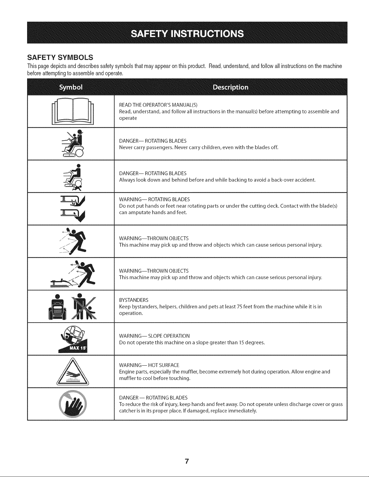
SAFETY SYMBOLS
Thispagedepictsand describessafety symbolsthatmay appearon this product. Read,understand,andfollowallinstructionson the machine
beforeattemptingto assembleandoperate.
0
A
READ THE OPERATOR'S MANUAL(S)
Read, understand, and follow all instructions in the manual(s) before attempting to assemble and
operate
DANGER-- ROTATING BLADES
Never carry passengers. Never carry children, even with the blades off.
DANGER-- ROTATING BLADES
Always look down and behind before and while backing to avoid a back-over accident.
WARNING-- ROTATING BLADES
Do not put hands or feet near rotating parts or under the cutting deck. Contact with the blade(s)
can amputate hands and feet.
WARNING--THROWN OBJECTS
This machine may pick up and throw and objects which can cause serious personal injury.
WARNING--THROWN OBJECTS
This machine may pick up and throw and objects which can cause serious personal injury.
BYSTANDERS
Keep bystanders, helpers, children and pets at least 75 feet from the machine while it is in
operation.
WARNING-- SLOPE OPERATION
Do not operate this machine on a slope greater than 15 degrees.
WARNING-- HOT SURFACE
Engine parts, especially the muffler, become extremely hot during operation. Allow engine and
muffler to cool before touching.
DANGER-- ROTATING BLADES
To reduce the risk of injury, keep hands and feet away. Do not operate unless discharge cover or grass
catcher is in its proper place. If damaged, replace immediately.
7
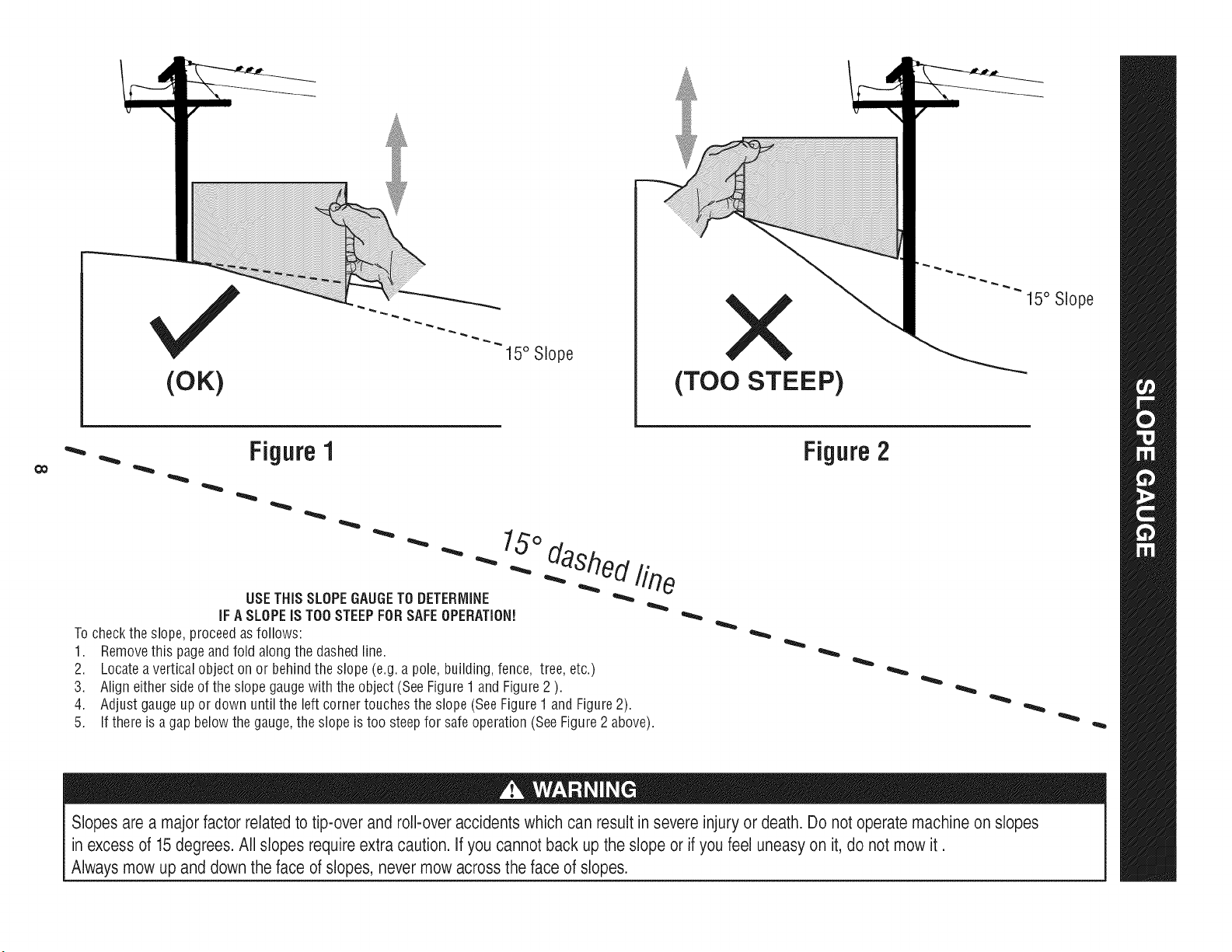
(OK)
15° Slope
X
(TOO STEEP)
15° Slope
'_. _ Figure1
USETHISSLOPEGAUGETODETERMINE
IFA SLOPEIS TOOSTEEPFORSAFEOPERATION!
To checkthe slope,proceedas follows:
1. Removethis pageandfold along the dashedline.
2. Locatea verticalobject onor behindthe slope (e.g. a pole, building,fence, tree, etc.)
3. Align eitherside of the slope gaugewith the object(SeeFigure1 and Figure2 ).
4. Adjust gaugeup or down until the left cornertouchesthe slope (SeeFigure1 and Figure2).
5.
15°
dashed line
If there is agap belowthe gauge,the slope is too steepfor safeoperation(SeeFigure2 above).
Figure2
Slopes are a majorfactor related to tip-over and roll-over accidents which can result in severe injury or death. Do not operatemachine on slopes
in excess of 15 degrees. All slopes require extra caution. If you cannot back up the slope or if you feel uneasy on it, do not mow it.
Always mow up and down the face of slopes, never mow across the face of slopes.
IMPORTANT:Yourtractoris shippedwithmotoroil in theengine.
However,you MUSTcheckthe oil levelbeforeoperating.Referto the
Service& Maintenancesectionfor instructionson checkingtheoil
level.
Attaching the Battery Cables
CALIFORNIA PROPOSITION 65
Batteryposts,terminals,andrelatedaccessoriescontainleadand
leadcompounds,chemicalsknownto the Stateof Californiato
causecancerand reproductiveharm.Washhandsafterhandling.
Whenattachingbatterycables,alwaysconnectthe POSITIVE(Red)
wireto its terminalfirst,followedby the NEGATIVE(Black)wire.
Forshippingreasons,bothbatterycablesonyourequipmentmay
havebeen left disconnectedfrom the terminalsat the factory.To
connectthe batterycables,proceedasfollows:
NOTE:Thepositivebatteryterminalis markedPos.(+).The negative
batteryterminalis markedNeg.(-).
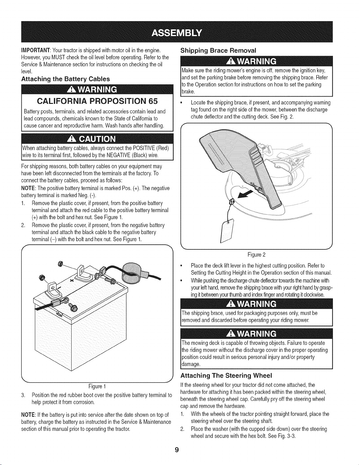
1. Removethe plasticcover,if present,fromthe positivebattery
terminaland attachthe redcableto the positivebatteryterminal
(+)withthe bolt andhexnut. See Figure1.
2. Removethe plasticcover,if present,fromthe negativebattery
terminaland attachthe blackcableto the negativebattery
terminal(-) withthe bolt andhex nut. See Figure1.
f
J
Figure1
3. Positionthe red rubber boot over the positivebatteryterminalto
helpprotectit from corrosion.
NOTE:If thebatteryis put into serviceafterthe dateshownon topof
battery,chargethe batteryas instructedinthe Service & Maintenance
sectionof this manualprior to operatingthe tractor.
Shipping Brace Removal
Makesurethe ridingmower'sengineis off, removetheignitionkey,
andset the parkingbrakebeforeremovingthe shippingbrace. Refer
Itothe Operationsectionfor instructionsonhowto setthe parking
lbrake.
• Locatethe shippingbrace,if present,and accompanyingwarning
tag foundonthe rightsideof the mower,betweenthe discharge
chutedeflectorand the cuttingdeck. See Fig. 2.
//
Figure2
Placethe deck lift leverinthe highestcuttingposition.Referto
SettingtheCuttingHeightin the Operationsectionof thismanual.
Whilepushingthedischargechuteddlectortowardsthemachinewith
yourlefthand,removetheshippingbracewithyourrighthandbygrasp-
ingitbetweenyourthumbandindexfingerandrotatingitclockwise.
The shippingbrace,usedfor packagingpurposesonly, mustbe
removedand discardedbeforeoperatingyour ridingmower.
The mowingdeck iscapableof throwingobjects.Failureto operate
the ridingmowerwithoutthe dischargecoverin the properoperating
Ipositioncould resultin seriouspersonalinjuryand/orproperty
ldamage.
Attaching The Steering Wheel
Ifthe steeringwheelfor yourtractordid notcomeattached,the
hardwarefor attachingit has beenpackedwithinthe steeringwheel,
beneaththe steeringwheelcap.Carefullypry off the steeringwheel
cap and removethe hardware.
1. Withthe wheelsof the tractorpointingstraightforward,placethe
steeringwheeloverthe steeringshaft.
2. Placethe washer(withthe cuppedsidedown)overthe steering
wheeland securewiththe hex bolt.SeeFig.3-3.
9
f
\
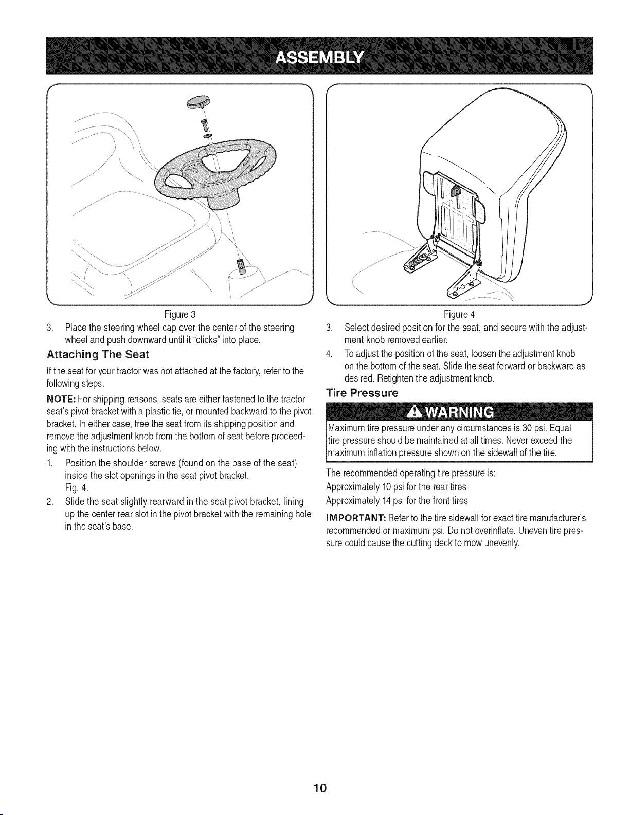
Figure3
3. Placethe steeringwheelcap overthe centerof the steering
wheeland pushdownwarduntilit "clicks"intoplace.
Attaching The Seat
If the seatfor yourtractorwasnotattachedat thefactory,refertothe
followingsteps.
NOTE: Forshippingreasons,seatsare eitherfastenedto the tractor
seat'spivotbracketwitha plastictie, or mountedbackwardto the pivot
bracket.Ineithercase,free the seatfromits shippingpositionand
removethe adjustmentknobfromthe bottomof seatbeforeproceed-
ingwiththe instructionsbelow.
1. Positionthe shoulderscrews(foundon the baseof the seat)
insidethe slot openingsin the seatpivot bracket.
Fig.4.
2. Slide the seat slightlyrearwardin the seatpivot bracket,lining
up the centerrear slot in thepivotbracketwith the remaininghole
in theseat'sbase.
Figure4
3. Selectdesired positionfor the seat,and secure with the adjust-
mentknobremovedearlier.
4. Toadjustthe positionof the seat,loosenthe adjustmentknob
on the bottomof the seat.Slidethe seatforwardor backwardas
desired.Retightenthe adjustmentknob.
Tire Pressure
X
Maximumtire pressureunderany circumstancesis 30 psi.Equal
tire pressureshouldbe maintainedat all times.Neverexceedthe
_maxmum nfat onpressureshownonthe s dewa of thet re.
The recommendedoperatingtire pressureis:
Approximately10psi forthe reartires
Approximately14psi forthe fronttires
IMPORTANT: Referto the tire sidewallfor exacttire manufacturer's
recommendedormaximumpsi.Donot overinfiate.Uneventirepres-
surecouldcausethe cuttingdeckto mowunevenly.
10
A
C
G
D
F
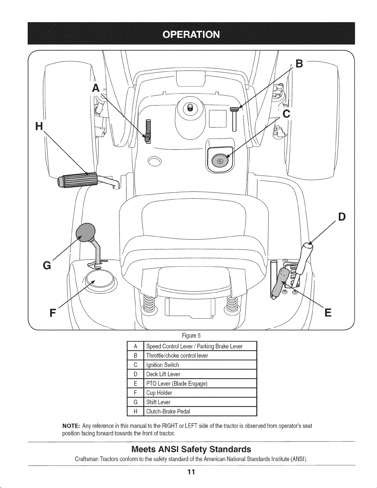
Figure5
A Speed ControlLever/ ParkingBrakeLever
B Throttle/chokecontrollever
C IgnitionSwitch
D DeckLiftLever
E PTOLever(BladeEngage)
F Cup Holder
G Shift Lever
H Clutch-BrakePedal
NOTE: Any referenceinthis manualto the RIGHTor LEFT sideof the tractoris observedfrom operator'sseat
positionfacingforwardtowardsthe frontof tractor.
Meets ANS! Safety Standards
CraftsmanTractorsconformto the safetystandardof theAmericanNationalStandardsInstitute(ANSI).
11
E
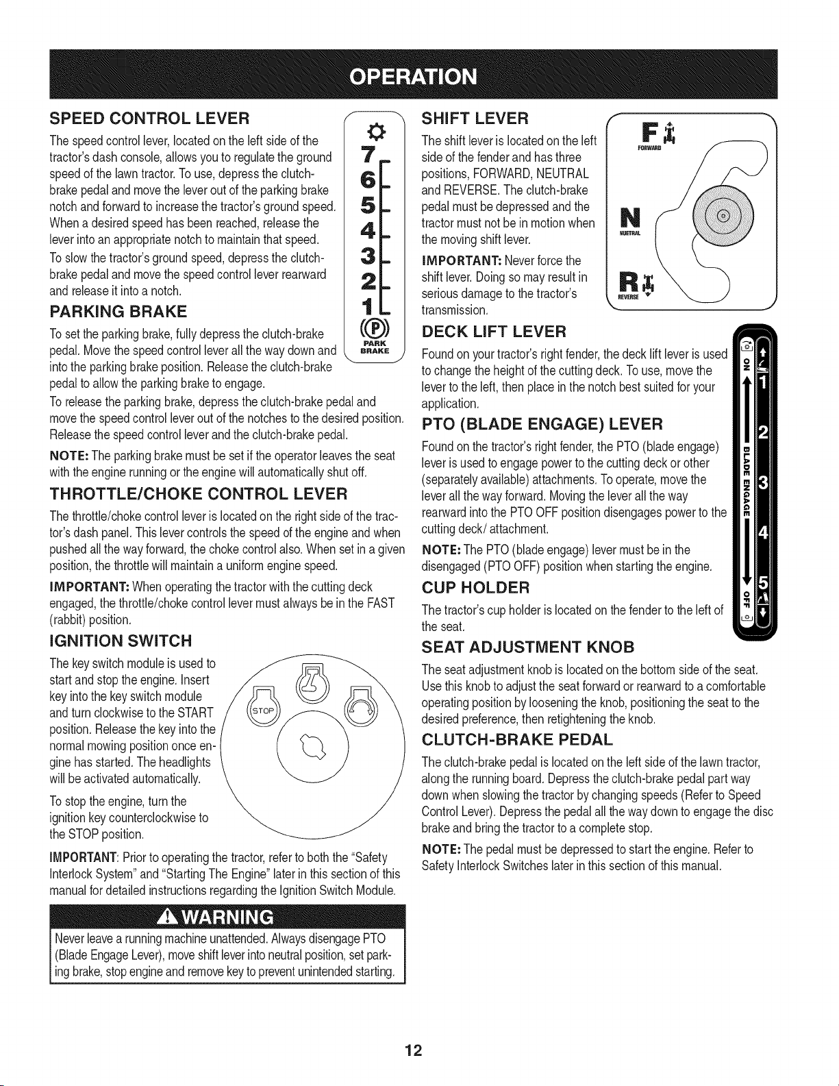
SPEED CONTROL LEVER
The speedcontrollever,locatedon the left sideof the
tractor'sdash console,allowsyouto regulatethe ground
speedof the lawntractor.To use,depressthe clutch-
brakepedaland movethe leverout of the parkingbrake
notchandforwardto increasethe tractor'sgroundspeed.
Whena desiredspeedhas beenreached,releasethe
leverintoan appropriatenotchto maintainthat speed.
Toslow thetractor'sgroundspeed,depressthe clutch-
brakepedaland movethe speedcontrolleverrearward
andreleaseit intoa notch.
PARKING BRAKE
Toset the parkingbrake,fullydepressthe clutch-brake
pedal.Movethe speedcontrolleverall the waydownand
intothe parkingbrakeposition.Releasethe clutch-brake
pedalto allowthe parkingbraketo engage.
To releasethe parkingbrake,depressthe clutch-brakepedaland
movethe speedcontrol leveroutof thenotchesto thedesiredposition.
Releasethe speedcontrolleverandthe clutch-brakepedal.
NOTE: The parkingbrakemustbe setif the operatorleavesthe seat
withtheengine runningor the enginewill automaticallyshutoff.
THROTTLE/CHOKE CONTROL LEVER
Thethrottle/chokecontrolleveris locatedon the rightsideof the trac-
tor'sdash panel.This levercontrolsthespeedof the engineandwhen
pushedall the wayforward,the chokecontrolalso.Whensetin a given
position,the throttlewill maintaina uniformenginespeed.
IMPORTANT: Whenoperatingthetractorwiththe cuttingdeck
engaged,the throttle/chokecontrollevermustalwaysbein the FAST
(rabbit)position.
IGNITION SWITCH
The keyswitch moduleis usedto
startand stopthe engine.Insert
keyintothe keyswitchmodule
andturnclockwiseto the START
position.Releasethekey into the
normalmowingpositiononceen-
ginehas started.The headlights
will be activatedautomatically.
Tostop theengine,turnthe
ignitionkeycounterclockwiseto
the STOPposition.
IMPORTANT:Priorto operatingthe tractor,referto boththe "Safety
InterlockSystem"and"StartingThe Engine"laterin this sectionof this
manualfor detailedinstructionsregardingthe IgnitionSwitchModule.
Neverleavea runningmachineunattended.AlwaysdisengagePTO
(BladeEngageLever),moveshiftleverinto neutralposition,setpark-
ingbrake,stopengineand removekey topreventunintendedstarting.
SHIFT LEVER
The shift leveris locatedon the left
side of the fenderand hasthree
positions,FORWARD,NEUTRAL
and REVERSE.The clutch-brake
pedalmustbedepressedand the
tractormustnot bein motionwhen
the movingshift lever.
IMPORTANT: Neverforcethe
shift lever.Doingso mayresultin
seriousdamageto thetractor's
transmission.
DECK LIFT LEVER
Foundonyourtractor'srightfender,the decklift leveris used
to changethe heightof thecuttingdeck.To use,movethe
leverto the left, thenplace inthe notchbest suitedfor your
application.
PTO (BLADE ENGAGE) LEVER
Foundonthe tractor'srightfender,the PTO(bladeengage)
leveris usedto engagepowerto the cuttingdeckorother
(separatelyavailable)attachments.Tooperate,move the
leverall thewayforward.Movingthe leverallthe way
rearwardinto the PTOOFFpositiondisengagespowerto the
cuttingdeck/attachment.
NOTE: The PTO(blade engage)levermustbein the
disengaged(PTOOFF)positionwhenstartingtheengine.
CUP HOLDER
The tractor'scup holderis locatedon the fenderto the left of
the seat.
SEAT ADJUSTMENT KNOB
The seat adjustmentknob is locatedon the bottomsideof the seat.
Usethis knobto adjustthe seat forwardor rearwardto a comfortable
operatingpositionby looseningthe knob,positioningthe seatto the
desiredpreference,then retighteningthe knob.
CLUTCH-BRAKE PEDAL
The clutch-brakepedalis locatedon the left sideof the lawntractor,
alongthe runningboard.Depressthe clutch-brakepedalpart way
downwhen slowingthe tractorbychangingspeeds(Referto Speed
ControlLever).Depressthe pedalall the waydownto engagethe disc
brakeand bring the tractorto a completestop.
NOTE: Thepedal mustbedepressedto startthe engine.Referto
SafetyInterlockSwitcheslaterin this sectionof this manual.
12
Gas and Oil Fill=up
0il
iMPORTANT: Yourtractorisshippedwith motoroil in the engine.
However,you MUSTcheckthe oil levelbeforeoperating.Becareful
not tooverfill.
For instructionsonhowto checkthe engineoil, referto CheckingThe
EngineOilin the ServiceandMaintenancesectionof this manual.
Gasoline
Thegasolinetank islocatedunderthe hood.Do notoverfill.
Useextremecarewhenhandlinggasoline.Gasolineis extremely
flammableandthe vaporsare explosive.Neverfuel machineindoors
orwhile theengineishotor running.Extinguishcigarettes,cigars,
p pes,andothersourcesof gn t on.
NOTE : Purchasegasolinein small quantities.Do notuse gasolineleft
overfrom the previousseason,to minimizegumdepositsin the fuel
system.
• Thisengineiscertifiedto operateon unleadedgasoline.For best
results,fill thefuel tankwithonlyclean,fresh,unleadedgasoline
witha pumpstickeroctaneratingof 87or higher.
• Gasohol(upto 10%ethylalcohol,90% unleadedgasolineby
volume)is an approvedfuel. Othergasoline/alcoholblends,such
as E85,arenot approved.
• MethylTertiaryButylEther(MTBE)andunleadedgasolineblends
(upto a maximumof 15%MTBEby volume)areapprovedfuels.
Othergasoline/etherblendsarenotapproved.
• Fill fueltankoutdoorsorinwell-ventilatedarea.
• Do notoverfillfuel tank. Filltankto no morethan 1/2inchbelow
bottomof fillerneck to allowspacefor fuel expansion.
• Neverremovegas cap oradd fuel whilethe engineishot or run-
ning.Allowengineto cool at leasttwo minutesbeforerefueling.
• If gasolineisspilled,wipe itoff the engineandequipment.Move
machineto anotherarea.Wait5 minutesbeforestartingthe
engine.
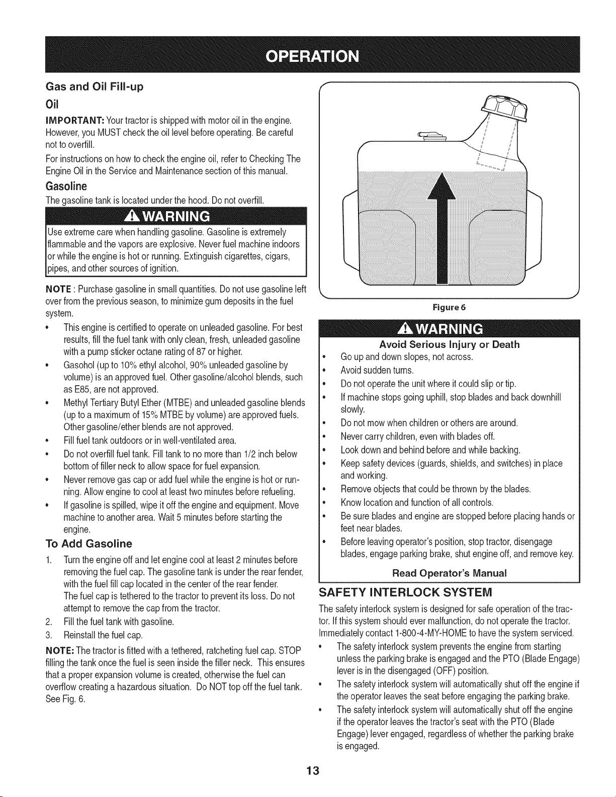
To Add Gasoline
1. Turnthe engineoff and let enginecoolat least2 minutesbefore
removingthe fuelcap. Thegasolinetankisunderthe rearfender,
withthe fuelfill cap locatedinthecenterof the rearfender.
Thefuel cap is tetheredto the tractorto preventits loss. Donot
attemptto removethe cap fromthetractor.
2. Fill thefuel tankwithgasoline.
3. Reinstallthe fuelcap.
NOTE: The tractoris fittedwitha tethered,ratchetingfuel cap.STOP
fillingthe tankonce the fuelis seeninsidethefiller neck. This ensures
thata properexpansionvolumeis created,otherwisethe fuel can
overflowcreatinga hazardoussituation. Do NOTtop offthe fuel tank.
SeeFig. 6.
Figure 6
Avoid Serious injury or Death
• Go upanddownslopes,notacross.
• Avoidsuddenturns.
• Donot operatethe unitwhereitcould slipor tip.
• Ifmachinestopsgoinguphill,stop bladesandbackdownhill
slowly.
• Donot mowwhenchildrenorothersare around.
• Nevercarrychildren,evenwithbladesoff.
• Lookdownand behind beforeand whilebacking.
• Keepsafetydevices(guards,shields,and switches)in place
andworking.
• Removeobjectsthatcould bethrownby the blades.
• Knowlocationandfunctionof allcontrols.
• Besurebladesandengineare stoppedbeforeplacinghandsor
feetnear blades.
• Beforeleavingoperator'sposition,stop tractor,disengage
blades,engageparkingbrake,shutengineoff, and removekey.
Read Operator's Manual
SAFETY INTERLOCK SYSTEM
The safetyinterlocksystemisdesignedfor safeoperationof the trac-
tor.If thissystemshouldevermalfunction,do notoperatethe tractor.
Immediatelycontact1-800-4-MY-HOMEto havethe systemserviced.
• The safetyinterlocksystempreventsthe enginefromstarting
unlessthe parkingbrakeis engagedandthe PTO(Blade Engage)
leveris inthe disengaged(OFF) position.
• The safetyinterlocksystemwill automaticallyshutoff the engineif
the operatorleavesthe seatbeforeengagingthe parkingbrake.
• The safetyinterlocksystemwill automaticallyshutoff the engine
iftheoperatorleavesthe tractor'sseatwiththe PTO(Blade
Engage)leverengaged,regardlessof whetherthe parkingbrake
isengaged.
13
• Theenginewill automaticallyshutoffif the PTO(BladeEngage)
leveris movedintothe engaged(ON)positionwith the shift lever
in Reverse.
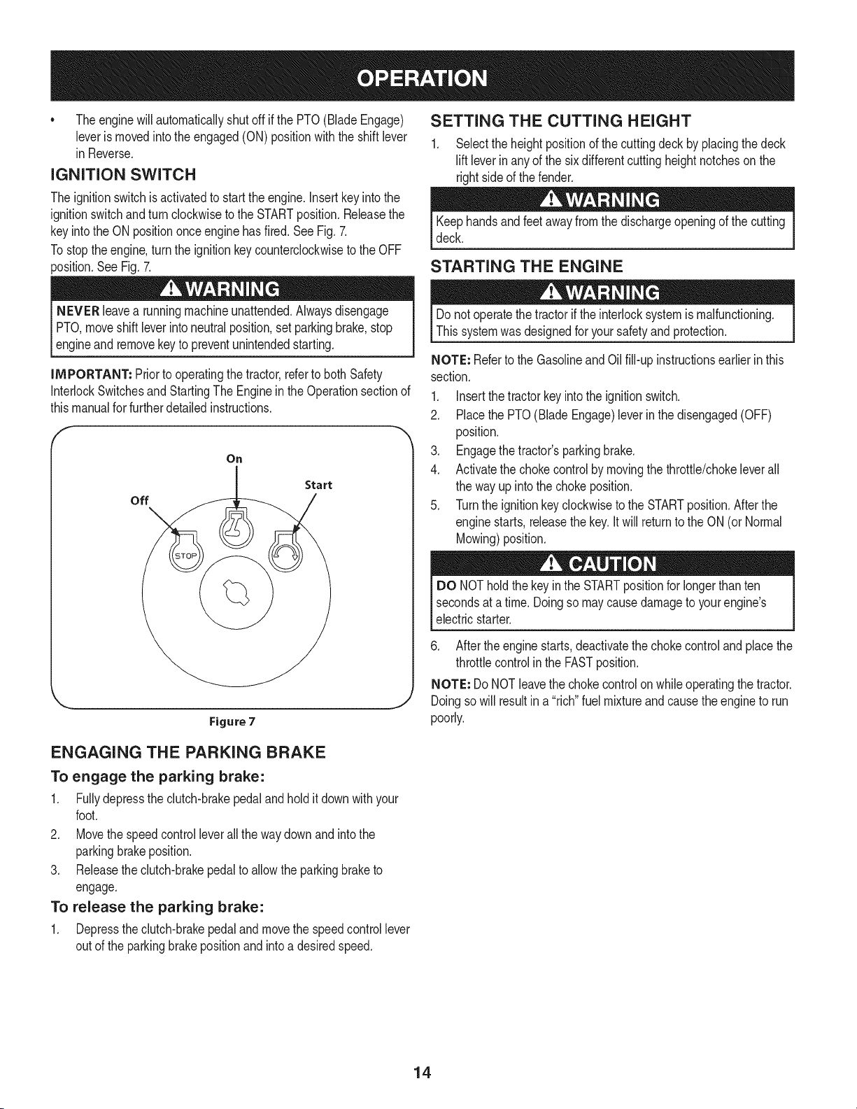
IGNITION SWITCH
The ignitionswitchis activatedto startthe engine.Insertkeyinto the
ignitionswitchand turnclockwiseto the STARTposition.Releasethe
keyintothe ON positiononceenginehasfired.SeeFig.7.
Tostop theengine,turnthe ignitionkey counterclockwiseto the OFF
position.SeeFig. 7.
NEVER leavea runningmachineunattended.Alwaysdisengage
PTO,moveshift leverintoneutralposition,set parkingbrake,stop
_engne and removekeyto preventunntendedstartng.
iMPORTANT: Prior to operatingthetractor,referto both Safety
InterlockSwitchesandStartingThe Enginein the Operationsectionof
thismanualfor furtherdetailedinstructions.
On
off
Start
Figure 7
SETTING THE CUTTING HEIGHT
1. Selectthe heightpositionof the cuttingdeckby placingthe deck
lift leverin anyof the sixdifferentcuttingheightnotcheson the
rightsideof the fender.
Keephandsandfeet awayfrom the dischargeopeningof the cutting
deck.
STARTING THE ENGINE
Donot operatethe tractorif the interlocksystemis malfunctioning.
Thissystemwasdesignedfor yoursafetyand protection.
NOTE: Referto the GasolineandOil fill-up instructionsearlierin this
section.
1. Insertthe tractorkey intothe ignitionswitch.
2. Placethe PTO(BladeEngage)leverinthe disengaged(OFF)
position.
3. Engagethe tractor'sparkingbrake.
4. Activatethe chokecontrolby movingthethrottle/chokeleverall
the way up into thechoke position.
5. Turnthe ignitionkeyclockwiseto the STARTposition.Afterthe
enginestarts,releasethe key.Itwill returnto the ON(or Normal
Mowing)position.
DO NOTholdthe key in the STARTpositionfor longerthanten
secondsat atime. Doingso maycausedamageto yourengine's
electricstarter.
6. After the enginestarts,deactivatethe chokecontroland placethe
throttlecontrolin the FASTposition.
NOTE: Do NOTleavethe chokecontrolonwhileoperatingthe tractor.
Doingso will resultin a "rich"fuel mixtureandcause theengineto run
poorly.
ENGAGING THE PARKING BRAKE
To engage the parking brake:
1. Fullydepressthe clutch-brakepedalandholdit downwithyour
foot.
2. Movethe speedcontrolleverallthe waydownand intothe
parkingbrakeposition.
3. Releasethe clutch-brakepedalto allowthe parkingbraketo
engage.
To release the parking brake:
1. Depressthe clutch-brakepedalandmovethe speedcontrollever
outof the parkingbrakepositionand intoa desiredspeed.
14
STOPPING THE ENGINE
Ifyou strikea foreignobject,stopthe engine,disconnectthe spark
plugwire(s)andgroundagainstthe engine.Thoroughlyinspectthe
machinefor anydamage.Repairthe damagebeforerestartingand
operating
If the bladesare engaged,placethe PTO(BladeEngage)leverin
the disengaged(OFF)position.
2. Turnthe ignitionkeycounterclockwiseto the STOPposition.
3. Removethekeyfrom the ignitionswitchto preventunintended
starting.
DRIVING THE TRACTOR
Avoidsuddenstarts,excessivespeedand suddenstops.
Do notleavethe seatof thetractorwithoutfirst placingthe PTO
(BladeEngage)leverinthe disengaged(OFF)position,depressing
the brakepedal and engagingthe parkingbrake.Ifleavingthetractor
unattended,alsoturn the ignitionkey off and removethe key.
Alwayslookdownandbehind beforeand whilebackingupto avoida
back-overaccident.
1. Depressthe clutch-brakepedal to releasethe parkingbrakeand
thenlet the pedal up.
2. Movethe throttleleverintothe FAST(rabbit) position.
3. Placethe shiftleverin eitherthe FORWARDor REVERSE
position.
IMPORTANT: DoNOTusethe shift leverto changethe directionof
travelwhenthe tractoris in motion.Alwaysusethe clutch-brakepedal
to bringthe tractorto a completestopbeforeshifting.
4. Releasethe parkingbrakebydepressingthe clutch-brakepedal
andpositioningthe speedcontrolleverinthe desiredposition.
IMPORTANT: First-timeoperatorsshouldusespeedpositions1 or
2. Becomecompletelyfamiliarwith the tractor'soperationandcontrols
beforeoperatingthe tractorinhigherspeedpositions.
5. Releaseclutch-brakepedalslowlyto put unit intomotion.
6. Thelawntractorisbroughtto a stopbydepressingthe clutch-
brakepedal.
NOTE: Whenoperatingthe unitinitially,therewill be little difference
betweenthe highesttwo speedsuntilafter the beltshaveseated
themselvesintothe pulleysduringthe break-inperiod.
WARNING!Beforeleavingthe operator'spositionfor any reason,
disengagethe blades,placethe shift leverinneutral,engagethe
parkingbrake,shutengineoff and removethe key.
1. Placethe shift leverinneutral,
2. Engagethe parkingbrake,
3. Shutengineoff and removethe key.Doingso will minimizethe
possibilityof havingyour lawn"browned"by hot exhaustfrom
yourtractor'srunningengine.
Ifunit stallswithspeedcontrolinhigh speed,or if unitwill not operate
with speedcontrolleverin a low speedposition,proceedasfollows:
1. Placeshift leverin NEUTRAL.
2. Restartengine.
3. Placespeedcontrolleverinhighestspeedposition.
4. Releaseclutch-brakepedal fully.
5. Depressclutch-brakepedal.
6. Placespeedcontrolleverindesiredposition.
7. Placeshift leverin either FORWARDor REVERSE,and follow
normaloperatingprocedures.
DRIVING ON SLOPES
Referto the SLOPEGAUGEinthe SafetyInstructionssectionof the
manualto helpdetermineslopeswhereyou mayoperatethis tractor
safely.
Donot mowon inclineswitha slopeinexcessof 15degrees(a rise
of approximately2-1/2feet every 10feet).The tractorcouldoverturn
andcause seriousinjury.
• Mowupanddown slopes,NEVERacross.
• Exerciseextremecautionwhenchangingdirectionon slopes.
Watchfor holes,ruts,bumps,rocks,or otherhiddenobjects.
Uneventerraincouldoverturnthe machine.Tallgrasscan hide
obstacles.
• Avoidturnswhendrivingon a slope.If a turnmustbe made,turn
downthe slope.Turningupa slopegreatlyincreasesthe chance
of a roll over.
• Avoidstoppingwhen drivingup a slope.If itis necessaryto stop
whiledrivingup a slope,start upsmoothlyandcarefullyto reduce
the possibilityof flippingthe tractoroverbackward.
ENGAGING THE BLADES
Engagingthe PTO(BladeEngage)transferspowerto the cuttingdeck
or other(separatelyavailable)attachments.Toengagethe blades,
proceedas follows:
1. Movethe throttle/chokecontrolleverto the FAST(rabbit)position.
2. Graspthe PTO(BladeEngage)leverandpivotit allthe way
forwardinto theengaged(ON) position.
3. Keepthethrottleleverin the FAST(rabbit)positionfor the most
efficientuseof the cuttingdeckor other(separatelyavailable)
attachments.
NOTE: Theenginewill automaticallyshutoff if the PTO(Blade
Engage)leveris movedintothe engaged(ON)positionwiththe shift
leverin Reverse.
IMPORTANT: Whenstoppingthe tractorfor any reasonwhileona
grasssurface,always:
15
MULCHING
A mulch kit is available as an attachment. Mulching is a process of
recirculating grass clippings repeatedly beneath the cutting deck.
The ultra-fine clippings are then forced back into the lawn where
they act as a natural fertilizer.
A mulchkitcan be purchased.See the ReplacementParts& Attach-
mentssectionof this manualfor moreinformation.
USING THE DECK LIFT LEVER
To raisethe cuttingdeck,movethe decklift leverto the left,then place
itin the notchbestsuitedfor yourapplication.Referto SettingThe
CuttingHeightearlierinthisOperationsection.
MOWING
Tohelp avoidbladecontactor a thrownobjectinjury,keepbystand-
ers,helpers,childrenandpetsat least 75 feet fromthe machine
[wh e t s n operaton. Stop roachne f anyoneentersthearea.
Thefollowinginformationwill be helpfulwhen usingthecuttingdeck
withyourtractor:
Planyour mowingpatternto avoiddischargeof materialstoward
roads,sidewalks,bystandersandthe like.Also,avoiddischarging
materialagainsta wallor obstructionwhich maycausedischarged
materialto ricochetback towardthe operator.
HEADLIGHTS
* The lampsareON wheneverthetractor'sengineis running.
o The lampsturn OFFwhenthe ignitionkeyismovedto the STOP
position.
Do not mowat high groundspeed,especiallyifa mulch kit or
grasscollectorisinstalled.
Forbest resultsit isrecommendedthatthe firsttwo lapsbe cut
withthedischargethrowntowardsthe center.Afterthe first two
laps,reversethe directionto throwthe dischargeto the outside
for the balanceof cutting.This willgive a betterappearanceto the
lawn.
Do notcut thegrasstoo short.Shortgrassinvitesweedgrowth
andyellowsquicklyindry weather.
Mowingshouldalwaysbe donewiththe engineat full throttle.
• Underheavierconditionsitmaybe necessaryto go back overthe
cutareaa secondtime to geta cleancut.
• Do NOTattemptto mowheavybrushand weedsand extremely
tall grass.Yourtractorisdesignedto mowlawns,NOTclear
brush.
• Keepthe bladessharpand replacethe bladeswhenworn. Refer
to CuttingBladesinthe Servicesectionof thismanualfor proper
bladesharpeninginstructions.
16
MAINTENANCE SCHEDULE
Beforeperforminganytypeof maintenance/service,disengageall
controlsandstoptheengine.Waituntilall movingpartshavecometo
acompletestop.Disconnectsparkplugwireandgrounditagainstthe
engineto preventunintendedstarting.Alwayswearsafetyglassesduring
operationorwhileperforminganyadjustmentsor repairs.
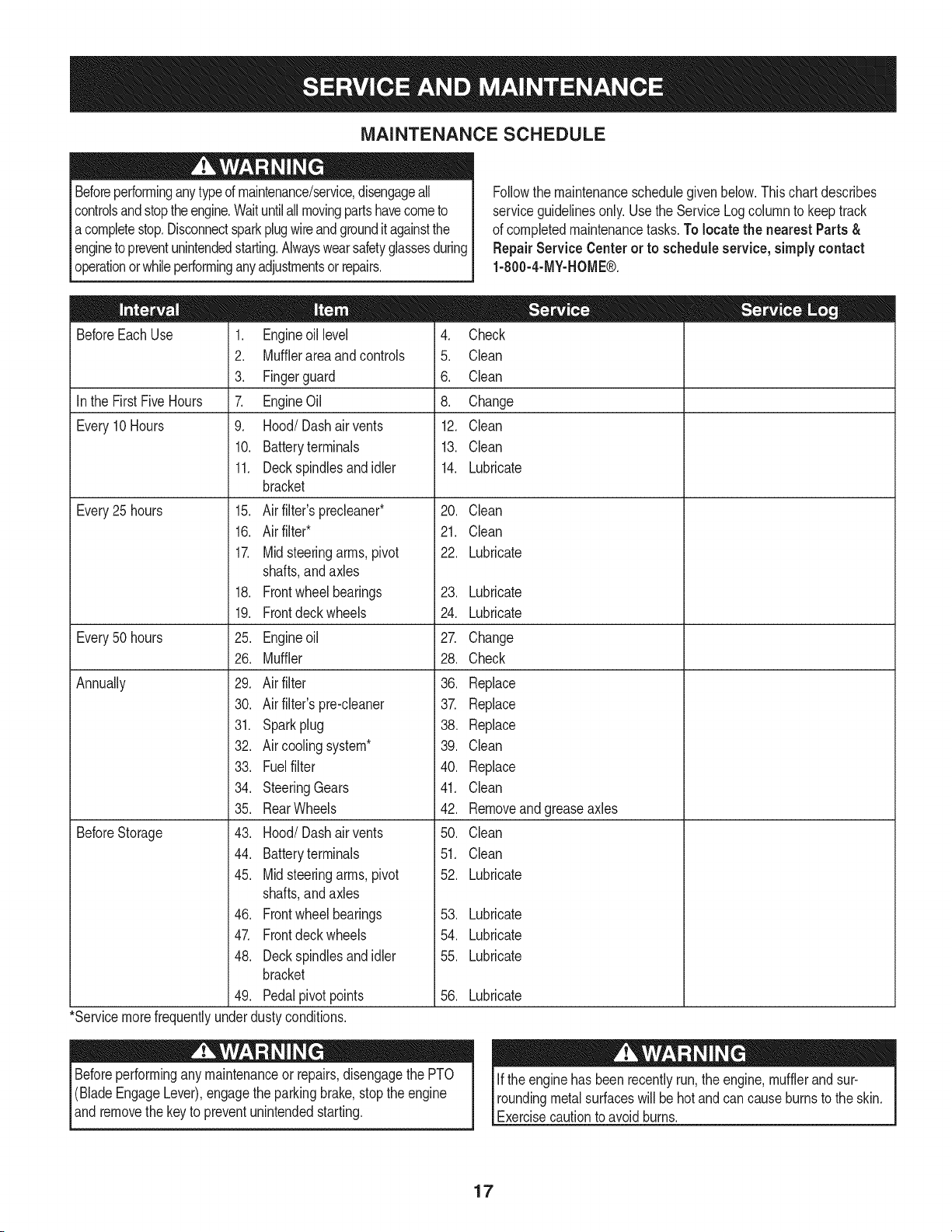
Followthe maintenanceschedulegivenbelow.Thischartdescribes
serviceguidelinesonly.Usethe ServiceLogcolumnto keeptrack
of completedmaintenancetasks.To locate the nearestParts&
Repair Service Centeror to scheduleservice,simplycontact
1-800-4-MY-HOME®.
BeforeEachUse
In the FirstFive Hours
Every10Hours
Every25 hours
Every50 hours
Annually
BeforeStorage
1. Engineoil level
2. Mufflerareaandcontrols
3. Fingerguard
7. EngineOil
9. Hood/Dashairvents
10. Batteryterminals
11. Deckspindlesand idler
bracket
15. Air filter'sprecleaner*
16. Air filter*
17. Midsteeringarms,pivot
shafts,andaxles
18. Frontwheelbearings
19. Frontdeck wheels
25. Engineoil
26. Muffler
29. Air filter
30. Air filter'spre-cleaner
31. Sparkplug
32. Air coolingsystem*
33. Fuelfilter
34. SteeringGears
35. RearWheels
43. Hood/Dash air vents
44. Batteryterminals
45. Midsteeringarms,pivot
shafts,andaxles
46. Frontwheelbearings
47. Frontdeckwheels
48. Deckspindlesand idler
bracket
49. Pedalpivot points
4. Check
5. Clean
6. Clean
8. Change
12. Clean
13. Clean
14. Lubricate
20. Clean
21. Clean
22. Lubricate
23. Lubricate
24. Lubricate
27. Change
28. Check
36. Replace
37. Replace
38. Replace
39. Clean
40. Replace
41. Clean
42. Removeand greaseaxles
50. Clean
51. Clean
52. Lubricate
53. Lubricate
54. Lubricate
55. Lubricate
56. Lubricate
*Servicemorefrequentlyunderdustyconditions.
Beforeperformingany maintenanceor repairs,disengagethe PTO
(BladeEngageLever),engagethe parkingbrake,stopthe engine
andremovethe keyto preventunintendedstarting.
If the enginehas beenrecentlyrun,the engine,mufflerandsur-
roundingmetalsurfaceswill be hot andcancauseburnsto the skin.
Exercisecautionto avoidburns.
17
ENGINE MAINTENANCE
Checking the Engine Oil
Onlyuse highqualitydetergentoil ratedwithAPIserviceclassification
SF,SG,SH, or SJ. Selectthe oil's SAEviscositygradeaccordingto
theexpectedoperatingtemperature.Followthe chartbelow.
Althoughmulti-viscosityoils (5W20,10W30,etc.)improvestarting
incold weather,they will resultinincreasedoil consumptionwhen
usedabove32°E Checkyourengine oil level morefrequentlyto avoid
possibleenginedamagefromrunninglowon oil.
f
Colder_ 32°F D"-Warmer
5W20
Oil Viscosity Chart
J
Figure9
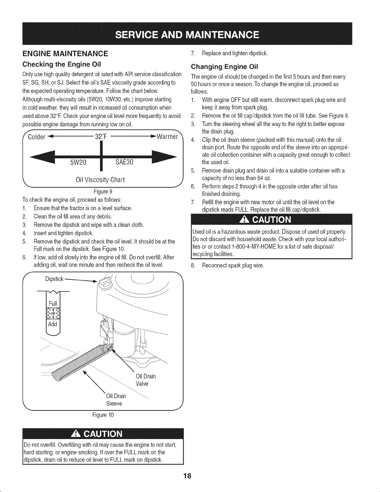
Tocheckthe engineoil, proceedas follows:
1. Ensurethat the tractoris ona levelsurface.
2. Cleantheoil fill areaof anydebris.
3. Removethe dipstickandwipe with a cleancloth.
4. Insertandtightendipstick.
5. Removethe dipstickandcheckthe oil level.It shouldbe at the
Fullmark on the dipstick.See Figure10.
6. If low,add oil slowlyintothe engineoilfill. Do notoverfill.After
addingoil,wait one minuteand thenrecheckthe oil level.
f
Dipstick_
7. Replaceandtightendipstick.
Changing Engine Oil
The engineoil shouldbe changedin the first 5 hoursandthenevery
50 hoursor once a season.To changethe engineoil, proceedas
follows:
1. WithengineOFFbut stillwarm,disconnectsparkplugwireand
keep it awayfromsparkplug.
2. Removethe oilfill cap/dipstickfromtheoil fill tube.SeeFigure9.
3. Turnthe steeringwheelall thewayto the rightto betterexpose
the drain plug.
4. Clip theoil drain sleeve(packedwith thismanual)ontothe oil
drainport. Routethe oppositeendof the sleeveintoanappropri-
ate oil collectioncontainerwith a capacitygreatenoughto collect
the usedoil.
5. Removedrainplugand drainoil intoa suitablecontainerwitha
capacityof no less than64 oz.
6. Performsteps2 through4 in theoppositeorderafteroil has
finisheddraining.
7. Refillthe enginewith newmotoroil untilthe oil levelon the
dipstickreadsFULL.Replacethe oilfill cap/dipstick.
Usedoil is a hazardouswasteproduct.Disposeof usedoil properly.
Do notdiscardwithhouseholdwaste.Checkwith your localauthori-
tiesoror contact 1-800-4-MY-HOMEfora list of safedisposal/
recyclingfacilities.
8. Reconnectsparkplugwire.
OilDrain
Valve
Oil Drain
Sleeve
Figure10
J
Do not overfill.Overfillingwithoil maycause theengineto notstart,
hardstarting,or engine smoking.If overthe FULLmarkon the
dipstick,drainoil to reduceoil levelto FULLmarkon dipstick.
18
Fuel Filter Air Cleaner
Gasolineandits vaporsare extremelyflammableandexplosive.Fire
or explosioncan causesevereburnsor death.
• Keepgasolineawayfromsparks,openflames,pilotlights,heat,
andotherignitionsources.
• Checkfuellines,tank,cap, and fittingsfrequentlyfor cracksor
leaks.Replaceif necessary.
• Beforereplacingthe fuel filter,drain the fueltank as perthe
instructionsbelow.
• Do notdrainfuel whentheengineis hot.Allowtheengine
adequatetimeto cool. Drainfuel intoan approvedcontainer
outdoors,awayfromopenflame.
• Drainany largevolumeof fuelfromthe tankby disconnectingthe
fuelline from the in-linefuel filter near theengine.
• Removethefuel linefromthe In-lineside (sidetowardsthe fuel
tank)of thefuel filter.
• Replacementpartsmustbethe sameand installedin the same
positionas the originalparts.
• If fuelspills,waituntil it evaporatesbeforestartingengine.
• Beforereplacingthe fuel filter,drain the fueltank. Otherwise,fuel
can leakoutand causea fireor explosion.
To Drainthe fuel:
1. Locatethefuel filter,whichisroutedon the leftsideof theengine
betweenthefueltankand thecarburetor,andmaybe attachedto
theenginewitha tie strap.Cutthetie strap,if present,thenpinch
thein-lineclampon thefuelfilterwitha pairof pliers,slidethe
clampupthefuelline. Pullthe fuellinefreefromthefilterandplace
theopenend of theline intoan approvedcontainerto drainthefuel.
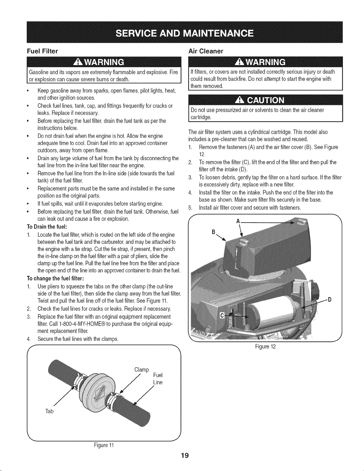
Tochangethe fuel filter:
1. Usepliersto squeezethe tabs on the otherclamp (theout-line
sided the fuel filter),thenslide theclamp awayfromthefuel filter.
Twistandpull the fuelline off of the fuelfilter.See Figure11.
2. Checkthefuel linesfor cracksor leaks.Replaceif necessary.
3. Replacethefuel filterwithanoriginalequipmentreplacement
filter.Call 1-800-4-MY-HOME®to purchasethe originalequip-
mentreplacementfilter.
Securethe fuel lineswith the clamps.
.
f
Iffilters,or coversare notinstalledcorrectlyseriousinjury or death
could resultfrom backfire.Do not attemptto startthe enginewith
themremoved.
Donot use pressurizedair orsolventsto cleanthe aircleaner
cartridge.
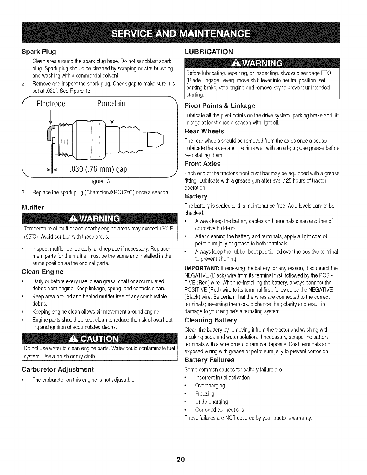
The air filter systemuses a cylindricalcartridge.This modelalso
includesa pre-cleanerthat can bewashedand reused.
1. Removethe fasteners(A)and the air filtercover(B). SeeFigure
12.
2. To removethe filter(C),lift the end of the filterand thenpullthe
filteroff the intake(D).
3. To loosendebris,gentlytap thefilter on a hardsurface.If thefilter
isexcessivelydirty, replacewitha newfilter.
4. Installthe filter on the intake.Pushthe endof the filter intothe
baseas shown.Makesurefilter fits securelyin the base.
5. Installair filtercoverandsecurewithfasteners.
A
B
Figure12
_J
Clamp
Fuel
Line
Tab
Figure11
19
Spark Plug
1. Cleanareaaroundthe sparkplugbase.Do not sandblastspark
plug.Sparkplugshouldbecleanedby scrapingorwire brushing
andwashingwitha commercialsolvent
2. Removeand inspectthe spark plug.Checkgapto makesureit is
setat .030".SeeFigure13.
Electrode Porcelain
.030 (.76 mm) gap
Figure13
J
3. Replacethe spark plug (Champion®RC12YC)oncea season.
Muffler
Temperatureof mufflerandnearbyengineareasmayexceed 150° F
(65°0).Avoidcontact with theseareas.
• Inspectmufflerperiodically,and replaceif necessary.Replace-
mentpartsfor the mufflermustbethe sameand installedin the
samepositionas the originalparts.
Clean Engine
• Dailyor beforeeveryuse,cleangrass,chaffor accumulated
debrisfromengine.Keeplinkage,spring,andcontrolsclean.
• Keepareaaroundandbehindmufflerfreeof any combustible
debris.
• Keepingenginecleanallowsairmovementaroundengine.
• Enginepartsshouldbe keptcleanto reducethe riskof overheat-
ingandignitionof accumulateddebris.
Do notuse waterto cleanengineparts.Watercouldcontaminatefuel
system.Usea brushor dry cloth.
Carburetor Adjustment
• Thecarburetoron this engineisnot adjustable.
LUBRICATION
Beforelubricating,repairing,or inspecting,alwaysdisengagePTO
(BladeEngageLever),moveshiftleverinto neutralposition,set
parkingbrake,stopengineand removekeyto preventunintended
starting.
Pivot Points & Linkage
Lubricateall the pivot pointson the drivesystem,parkingbrakeandlift
linkageat leastoncea seasonwith lightoil.
Rear Wheels
The rear wheelsshouldberemovedfromthe axlesonce aseason.
Lubricatethe axles and the rimswellwith an all-purposegreasebefore
re-installingthem.
Front Axles
Eachendof thetractor'sfrontpivotbar may be equippedwith a grease
fitting.Lubricatewitha greasegunafterevery25hoursof tractor
operation.
Battery
The batteryissealedand ismaintenance-free.Acidlevelscannotbe
checked.
• Alwayskeepthe batterycablesand terminalscleanandfree of
corrosivebuild-up.
Aftercleaningthe batteryand terminals,applya lightcoatof
petroleumjelly orgreaseto bothterminals.
• Alwayskeepthe rubberbootpositionedoverthe positiveterminal
to preventshorting.
iMPORTANT: If removingthe batteryfor any reason,disconnectthe
NEGATIVE(Black)wirefromitsterminalfirst,followedby the POSI-
TIVE(Red)wire.Whenre-installingthe battery,alwaysconnectthe
POSITIVE(Red)wireto its terminalfirst,followedbythe NEGATIVE
(Black)wire.Becertainthat the wiresareconnectedto the correct
terminals;reversingthemcouldchangethe polarityandresultin
damageto your engine'salternatingsystem.
Cleaning Battery
Cleanthe batteryby removingitfromthe tractorand washingwith
a bakingsodaandwatersolution.Ifnecessary,scrape thebattery
terminalswitha wirebrushto removedeposits.Coatterminalsand
exposedwiringwith greaseor petroleumjellyto preventcorrosion.
Battery Failures
Somecommoncausesfor batteryfailureare:
Incorrectinitialactivation
• Overcharging
• Freezing
• Undercharging
• Corrodedconnections
Thesefailuresare NOTcoveredby yourtractor'swarranty.
20
CLEANING THE ENGINE AND DECK
Anyfuel oroil spilledon the machineshouldbe wipedoff promptly.Do
NOTallowdebristo accumulatearoundthecoolingfinsof the engine
oron anyotherpart of the machine.
IMPORTANT: The useof a pressurewasherto cleanyour tractoris
NOTrecommended.It maycausedamageto electricalcomponents,
spindles,pulleys,bearingsor theengine.
A screwplugcan befoundon yourtractor'sdecksurfaceas seenin
Fig.14.This plug can bereplacedwith a waterport to be usedas part
of a separately-availabledeckwashsystem.
The DeckWash SystemTM is used to rinsegrassclippingsfrom the
deck'sundersideand preventthe buildupof corrosivechemicals.
NOTE: A deckwash systemcan be purchasedthroughthe retail
locationinwhich you purchasedthis tractor.For moreinformation,call
1-800-4-MY-HOME®.
f
Figure14
ADJUSTMENTS
Neverattemptto makeanyadjustmentswhilethe engineis running,
exceptwherespecifiedin theoperator'smanual.
Leveling the Deck
NOTE: Checkthe tractor'stire pressurebeforeperforminganydeck
levelingadjustments.Referto Tires in theServicesectionof this
manualfor moreinformationregardingtire pressure.
Front To Rear
Thefront of the cuttingdeckis supportedbya stabilizerbar that can
beadjustedto levelthe deckfromfrontto rear.Thefront of the deck
shouldbe between1A-inchand3A-inchlowerthanthe rear of the deck.
Adjustif necessaryas follows:
1. Withthetractorparkedon a firm,levelsurface,placethe lever
for liftingthe platformon the secondto the top notch(second
highestposition)androtatethe bladeas close as possibleto the
dischargechannelthat is parallelto thetractor.
2. Measurethedistancefromthe frontof the bladetip to theground
andthe rearof the bladetip tothe ground.Thefirst measure-
menttakenshouldbe between1A"and3A"less thanthe second
measurement.Determinetheapproximatedistancenecessaryfor
properadjustmentand proceed,if necessary,to the next step.
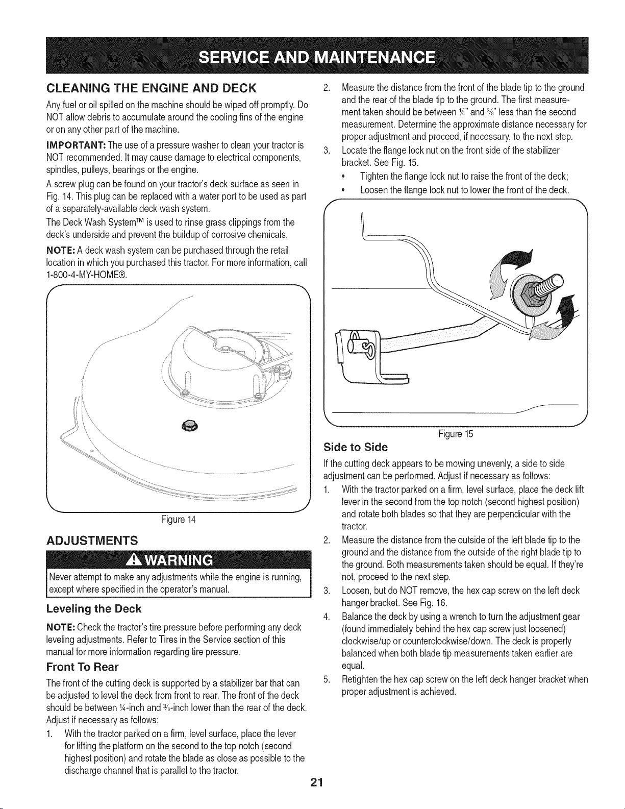
3. Locatethe flangelocknut onthe frontsideof the stabilizer
bracket.SeeFig. 15.
• Tightenthe flangelocknutto raisethe frontof the deck;
• Loosentheflangelock nutto lowerthe frontof thedeck.
Figure15
Side to Side
Ifthe cuttingdeckappearsto be mowingunevenly,a sideto side
adjustmentcan beperformed.Adjustif necessaryas follows:
1. Withthe tractorparkedona firm, levelsurface,placethe decklift
leverin the secondfromthe top notch (secondhighestposition)
and rotatebothbladesso thattheyare perpendicularwith the
tractor.
2. Measurethedistancefromthe outsideof the left bladetip to the
groundandthe distancefromthe outsideof the rightbladetip to
the ground.Bothmeasurementstaken shouldbeequal.Ifthey're
not,proceedto the next step.
3. Loosen,but do NOTremove,the hex capscrewonthe left deck
hangerbracket.SeeFig.16.
4. Balancethe deckby usinga wrenchto turnthe adjustmentgear
(foundimmediatelybehindthe hex cap screwjustloosened)
clockwise/upor counterclockwise/down.Thedeck is properly
balancedwhenboth bladetip measurementstakenearlierare
equal.
5. Retightenthe hexcap screwon the left deck hangerbracketwhen
properadjustmentis achieved.
21
HexCap Screw
,J
Figure16
Seat Adjustment
Referto the Assemblysectionof this manualfor seatadjustment
instructions.
Parking Brake Adjustment
Neverattemptto adjustthebrakeswhiletheengineis running.Always
disengagePTO(bladeengage)lever,moveshiftleverintoneutral
3osifion,stopengineandremovekeyto preventunintendedstarting.
the tractordoesnot cometo a completestopwhenthe brakepedal
is completelydepressed,or if the tractor'srearwheelscan roll with the
parkingbrakeapplied,the brakeis in needof adjustment.Contactthe
nearest Sears Service Center to haveyour brakesproperlyadjusted.
Tolocatethe nearest Parts& Repair Service Centeror to schedule
service,contact 1-800-4-MY-HOME®.
CUTTING DECK REMOVAL
To remove the cutting deck, proceed as follows:
1. Placethe PTO(BladeEngage)leverin the disengaged(OFF)
positionand engagetheparkingbrake.
2. Lowerthe deck by movingthe deck lift lever intothe bottom
notchon the rightfender.
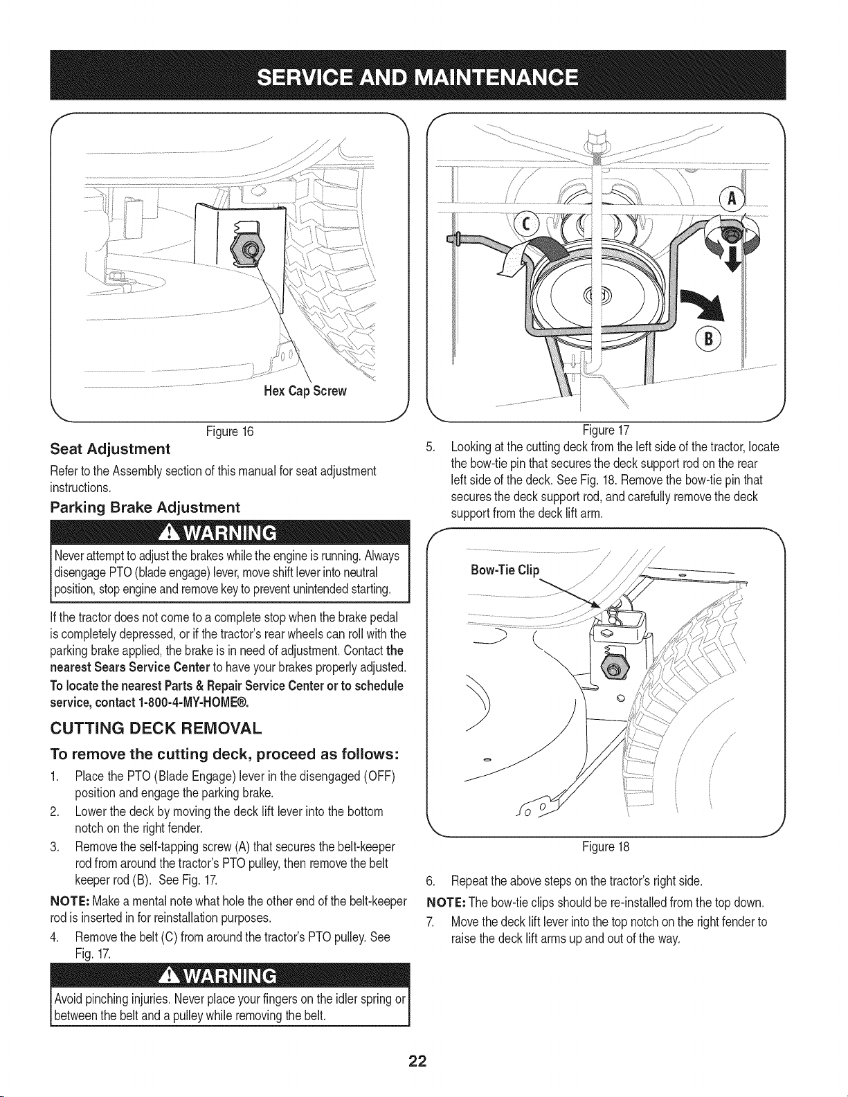
3. Removethe self-tappingscrew(A)that securesthe belt-keeper
rodfromaroundthetractor's PTOpulley,then removethe belt
keeperrod (B). See Fig.17.
NOTE: Makea mentalnotewhatholethe otherend of the belt-keeper
rodis insertedinfor reinstallationpurposes.
4. Removethe belt(C) from aroundthe tractor'sPTOpulley.See
Fig. 17.
C
f
.J
Figure17
Lookingat thecuttingdeckfromthe leftside of thetractor,locate
the bow-tiepin that securesthe decksupport rod on the rear
left sideof the deck. SeeFig.18.Removethe bow-tiepinthat
securesthe deck support rod,andcarefullyremovethe deck
supportfromthe decklift arm.
Bow-TieClip
/
/
/
/ /
Figure18
J
6. Repeatthe abovestepson the tractor'srightside.
NOTE: Thebow-tieclips shouldbe re-installedfromthe topdown.
7. Movethedeck lift leverintothe top notchon the rightfenderto
raisethedecklift arms up and out of the way.
Avoidpinchinginjuries.Neverplaceyour fingersonthe idlerspringor
betweenthe belt and a pulleywhile removingthe belt.
22
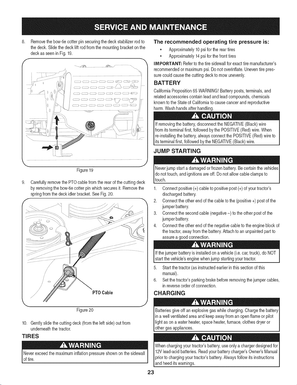
8. Removethebow-tiecotter pinsecuringthe deckstabilizerrodto
the deck.Slidethedecklift rod from the mountingbracketon the
deckas seenin Fig. 19.
f -,
........,j_!_ _;_ _ .....,
The recommended operating tire pressure is:
Approximately10psifor the reartires
Approximately14psi for thefront tires
IMPORTANT: Referto the tire sidewallfor exacttire manufacturer's
recommendedormaximumpsi.Donot overinfiate.Uneventirepres-
surecouldcausethe cuttingdeckto mowunevenly.
BATTERY
CaliforniaProposition65 WARNING!Batteryposts,terminals,and
relatedaccessoriescontainleadandleadcompounds,chemicals
knownto the Stateof Californiato causecancerand reproductive
harm.Washhandsafter handling.
If removingthe battery,disconnectthe NEGATIVE(Black)wire
fromitsterminalfirst,followedbythe POSFIVE(Red)wire.When
re-installingthe battery,alwaysconnectthe POSITIVE(Red)wireto
ts termna f rst,fo owedby the NEGATVE (Back) w re.
JUMP STARTING
.
Figure19
Carefullyremovethe PTOcablefromthe rearof the cuttingdeck
by removingthe bow-tiecotter pin which securesit. Removethe
springfromthe deckidlerbracket.SeeFig.20.
Neverjump starta damagedor frozenbattery.Be certainthe vehicles
do nottouch,andignitionsare off. Do notallowcable clampsto
touch.
1. Connectpositive(+)cableto positivepost(+)of yourtractor's
dischargedbattery.
2. Connectthe otherendof the cableto the(positive+)post of the
jumperbattery.
3. Connectthe secondcable (negative-) to the otherpostof the
jumperbattery.
4. Connectthe otherendof the negativecableto the engineblockof
the tractor,awayfromthe battery.Attachto anunpaintedpartto
assurea goodconnection.
Figure20
10. Gentlyslidethe cuttingdeck(from theleft side)out from
underneaththe tractor.
TIRES
Neverexceedthemaximuminflationpressureshownonthe sidewall
of tire.
Ifthejumper batteryis installedon a vehicle (i.e.car, truck), do NOT
start the vehicle'senginewhenjump startingyourtractor.
5. Startthe tractor(as instructedearlierin thissectionof this
manual).
6. Setthe tractor'sparkingbrakebeforeremovingthejumpercables,
inreverseorderof connection.
CHARGING
Batteriesgive off an explosivegas whilecharging.Chargethe battery
in a wellventilatedareaand keepawayfrom an openflame or pilot
light as ona waterheater,spaceheater,furnace,clothesdryeror
othergas appliances.
Whenchargingyourtractor'sbattery,useonlya chargerdesignedfor I
12Vlead-acidbatteries.Readyourbatterycharger_s Owner'sManualI
priorto chargingyourtractors battery.Alwaysfollowits instructions I
_andheed tswarnngs. J
23
Ifyour tractorhasnot beenputinto usefor anextendedperiodof time,
chargethe batteryas follows:
1. Setyour batterychargerto delivera maxof 10amperes.
Ifyour batterychargeris automatic,chargethe batteryuntilthe
chargerindicatesthatchargingis complete.Ifthe chargeris not
automatic,chargefor nofewerthaneight hours.
FUSE
One20 AMPfuseis installedin yourtractor'swiring harnessto protect
thetractor'selectricalsystemfrom damagecausedby excessive
amperage.
Ifthe electricalsystemdoesnot function,or yourtractor'senginewill
notcrank,first checkto becertainthatthe fuse hasnot blown.It can
befoundat the rearof the unit,underneaththe fenderlocatedby the
battery.
Alwaysusea fuse with the sameamperagecapacityfor replacement.
CUTTING BLADES
Shutthe engineoffand removeignitionkeybeforeremovingthe
cuttingblade(s)for sharpeningor replacement.Protectyourhands
_byusng heavyg oves whengraspngthe bade.
Periodicallyinspectthe bladeand/or spindleforcracksor damage,
especiallyafter you'vestrucka foreignobject. Donot operatethe
machineuntil damagedcomponentsare replaced.
To removetheblades, proceedas follows.
1. Removethe deckfrombeneaththe tractor,(referto CuttingDeck
Removalearlierinthis section)thengently flip thedeck overto
exposeitsunderside.
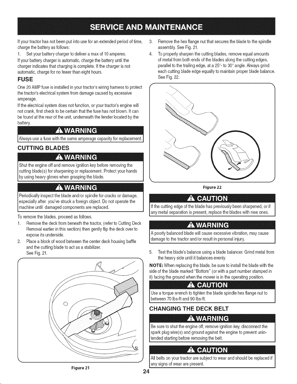
2. Placea blockof wood betweenthe centerdeckhousingbaffle
andthe cuttingbladeto act asa stabilizer.
SeeFig. 21.
.
4.
Removethe hexflangenut thatsecuresthe bladeto the spindle
assembly.SeeFig.21.
To properlysharpenthecutting blades,removeequalamounts
of metalfrombothendsof the bladesalongthe cuttingedges,
parallelto the trailingedge,at a 250.to 300angle.Alwaysgrind
eachcuttingbladeedge equallyto maintainproperbladebalance.
See Fig.22.
Figure 22
Ifthe cuttingedgeof the bladehas previouslybeensharpened,or if
any metalseparationis present,replacethe bladeswith new ones.
A poorlybalancedbladewill causeexcessivevibration,maycause
damageto thetractorand/or resultin personalinjury.
5. Testthe blade'sbalanceusinga bladebalancer.Grindmetalfrom
the heavy sideuntil it balancesevenly.
NOTE: Whenreplacingthe blade,be sureto installthe bladewith the
side of the blade marked"Bottom" (or with a partnumberstampedin
it) facingthe groundwhenthe moweris inthe operatingposition.
Usea torquewrenchto tightenthe bladespindlehexflangenut to
between70Ibs-ftand90Ibs-ft.
CHANGING THE DECK BELT
Besureto shut the engineoff, removeignitionkey,disconnectthe
sparkplugwire(s)and groundagainstthe engineto preventunin-
tendedstartingbeforeremovingthe belt.
All beltsonyourtractorare subjectto wearandshouldbereplacedif
J
any signsof wear are present.
Figure21
24
iMPORTANT: The V-beltfoundon yourtractoris speciallydesigned
to engageand disengagesafely.A substitute(non-OEM)V-beltcan
bedangerousby notdisengagingcompletely.Fora properworking
machine,useidenticalequipmentbeltsas listedin the partspagesof
thisOperator'sManual.
Tochangeor replacethedeckbelt onyourtractor,proceedas follows:
1. Removethedeck as instructedearlierinthis section.
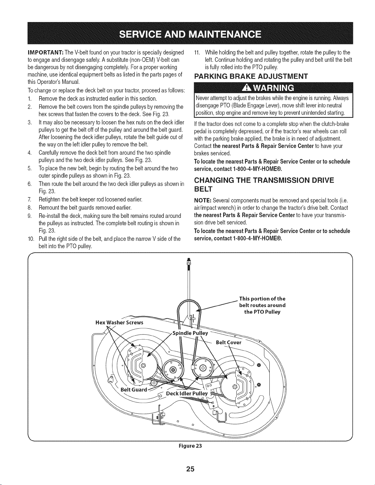
2. Removethebelt coversfromthe spindlepulleysby removingthe
hexscrewsthat fastenthe coversto the deck.SeeFig.23.
3. It mayalso benecessaryto loosenthe hex nutson thedeck idler
pulleysto getthe belt offof the pulleyand aroundthe belt guard.
Afterlooseningthe deck idler pulleys,rotatethe belt guideout of
the wayon the leftidlerpulleyto removethe belt.
4. Carefullyremovethe deck beltfromaroundthe twospindle
pulleysand thetwo deckidler pulleys.See Fig.23.
5. Toplacethe newbelt,beginby routingthe beltaroundthe two
outerspindlepulleysas shownin Fig.23.
6. Thenroutethe beltaroundthe twodeck idler pulleysas shownin
Fig.23.
7. Retightenthe belt keeperrodloosenedearlier.
8. Remountthe beltguardsremovedearlier.
9. Re-installthe deck,makingsurethe belt remainsroutedaround
the pulleysas instructed.Thecompletebelt routingis shownin
Fig.23.
Pullthe rightsideof thebelt,and placethe narrowV sideof the
belt intothe PTOpulley.
10.
F
11. Whileholdingthe belt andpulleytogether,rotatethe pulleyto the
Idt. Continueholdingand rotatingthe pulleyandbelt untilthe belt
isfully rolledintothe PTOpulley.
PARKING BRAKE ADJUSTMENT
Neverattempttoadjustthe brakeswhilethe engineis running.Always
disengagePTO(BladeEngageLever),moveshiftleverintoneutral
3osition,stopengineandremovekeyto preventunintendedstarting.
Ifthe tractordoesnotcometo a completestopwhentheclutch-brake
pedalis completelydepressed,or if the tractor'srearwheelscan roll
withthe parkingbrakeapplied,thebrakeis inneedof adjustment.
Contactthe nearest Parts & Repair Service Centerto haveyour
brakesserviced.
Tolocatethe nearestParts& RepairServiceCenteror to schedule
service,contact1-800-4-MY-HOME®.
CHANGING THE TRANSMISSION DRIVE
BELT
NOTE: Severalcomponentsmustbe removedandspecialtools(i.e.
air/impactwrench)in orderto changethetractor'sdrivebelt. Contact
the nearest Parts& Repair Service Centerto haveyourtransmis-
siondrivebelt serviced.
Tolocatethe nearestParts& RepairServiceCenteror to schedule
service,contact1-800-4-MY-HOME®.
This portion of the
belt routes around
the PTO Pulley
Figure 23
25
Neverstorelawntractorwithfuel intankindoorsor in poorly
ventilatedareaswherefuel fumesmay reachan openflame,spark,
or pilot lightas ona furnace,waterheater,clothesdryer,or gas
appliance.
PREPARING THE ENGINE
IMPORTANT:Fuelleft in the fueltank duringwarmweatherdeterio-
ratesandwillcauseseriousstartingproblems.
To preventgumdepositsfrom forminginsidethe engine'scarburetor
andcausingpossiblemalfunctionof theengine,the fuelsystemmust
be eithercompletelyemptied,or the gasolinemustbetreatedwith a
stabilizerto preventdeterioration.
1. If usinga fuel stabilizer:
a. Readthe productmanufacturer'sinstructionsandrecom-
mendations.
b. Add to clean,freshgasolinethe correctamountof stabilizer
for the capacityof the fuelsystem.
c. Fillthe fueltank with treatedfuel andrun the enginefor 2-3
minutesto get stabilizedfuel intothe carburetor.
2. Ifemptyingthe fuel system:
a. Donot drainfuel whenthe engineis hot.Allowthe engine
adequatetimeto cool.Drainfuelinto an approvedcontainer
outdoors,awayfromopen flame.
b. Drainany largevolumeof fuel fromthetankby disconnect-
ingthe fuel linefromthe in-linefuel filternearthe engine.
Seethe completeinstructionsfor DrainingThe Fuellaterin
this section.
Gasolineis extremelyflammableandcan beexplosiveundercertain
conditions.Draingasolinebeforestoringthe equipmentfor extended
periods.Drainfuel onlyinto anapprovedcontaineroutdoors,away
froman openflame.Allowengineto cool.Extinguishcigarettes,
cigars,pipes, and othersourcesof ignitionpriorto drainingfuel.
Storegasolinein an approvedcontainerin safe location.
c. Reconnectthe fuel lineand run the engineuntilit startsto
falter,thenusethe choketo keepthe enginerunninguntilall
fuel in the carburetorhas beenexhausted.
d. Disconnectthefuel lineanddrainany remaininggasoline
fromthe system.
DRAINING THE FUEL
1. Locatethe fuel filter,whichis locatedon theleft sideof the
engine,and maybe attachedto the enginewith a tie strap.
2. Cut the tie strap,if present,then pinchthe in-lineclamponthe
fuel filter with a pairof pliers,slidethe clampupthe fuel line.
3. Pullthe fuel linefreefrom the filterand placetheopenend of the
line intoan approvedcontainerto drain the fuel.
PREPARING THE LAWN TRACTOR
1. Cleanand lubricatetractorthoroughlyas describedin the lubrica-
tion instructions.
2. Donot usea pressurewasheror gardenhoseto cleanyour unit.
3. Store mowerin a dry,cleanarea. Do notstore nextto corrosive
materials,suchas fertilizer.
Gasolineis a toxic substance.Disposeof gasolineproperly.Contact
yourlocalauthoritiesforapproveddisposalmethods.
3. Removethe sparkplugand pour one (1) ounceof engineoil
throughthe sparkplughole intothe cylinder.Crankthe engine
severaltimesto distributethe oil. Replacethe sparkplug.
26
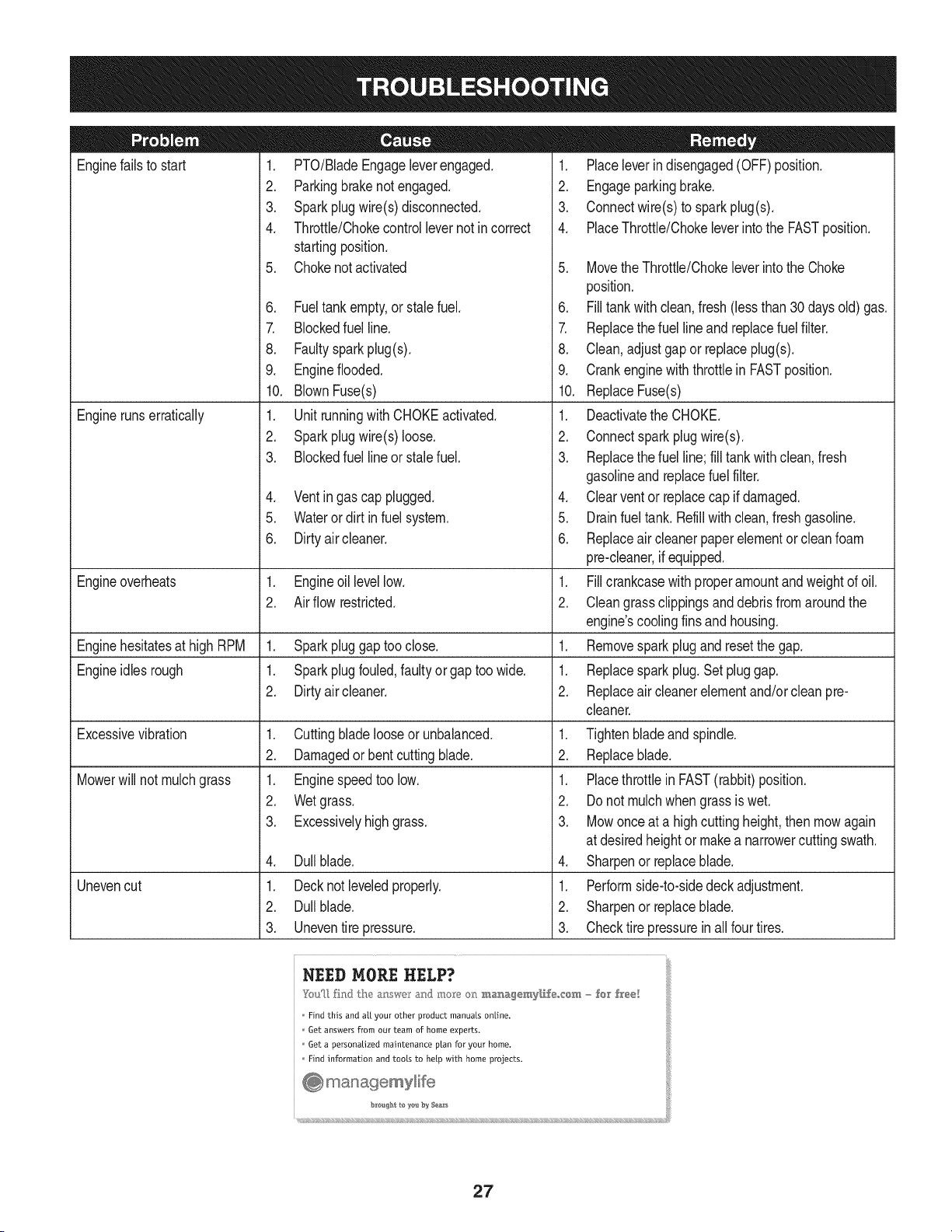
Enginefailsto start
Enginerunserratically
1. PTO/BladeEngageleverengaged.
2. Parkingbrakenotengaged.
3. Sparkplugwire(s)disconnected.
4. Throttle/Chokecontrollevernot incorrect
startingposition.
5. Chokenotactivated
6. Fueltank empty,or stalefuel.
7. Blockedfuel line.
8. Faultysparkplug(s).
9. Engineflooded.
10. BlownFuse(s)
1. Unit runningwithCHOKEactivated.
2. Sparkplugwire(s)loose.
3. Blockedfuel line or stalefuel.
4. Ventin gas cap plugged.
5. Wateror dirt in fuel system.
6. Dirtyair cleaner.
Engineoverheats 1. Engineoil levellow. 1.
2. Air flow restricted. 2.
Enginehesitatesat high RPM 1. Sparkpluggaptoo close. 1.
Engineidles rough 1. Sparkplugfouled,faultyor gaptoo wide. 1.
2. Dirtyair cleaner. 2.
Excessivevibration
Mowerwill not mulchgrass
Unevencut
1. Cuttingblade looseor unbalanced.
2. Damagedorbent cuttingblade.
1. Enginespeedtoo low.
2. Wetgrass.
3. Excessivelyhigh grass.
4. Dullblade.
1. Decknot leveledproperly.
2. Dullblade.
3. Uneventire pressure.
1. Placeleverindisengaged(OFF) position.
2. Engageparkingbrake.
3. Connectwire(s) to sparkplug(s).
4. PlaceThrottle/Chokeleverintothe FASTposition.
5. MovetheThrottle/Chokeleverintothe Choke
position.
6. Filltankwith clean,fresh (less than 30days old) gas.
7. Replacethe fuel lineandreplacefuel filter.
8. Clean,adjustgap or replaceplug(s).
9. Crankenginewith throttlein FASTposition.
10. ReplaceFuse(s)
1. Deactivatethe CHOKE.
2. Connectsparkplug wire(s).
3. Replacethe fuel line;fill tankwithclean,fresh
gasolineandreplacefuel filter.
4. Clearventor replacecap if damaged.
5. Drainfuel tank. Refillwith clean,fresh gasoline.
6. Replaceair cleanerpaperelementor cleanfoam
pre-cleaner,if equipped.
Fillcrankcasewithproperamountandweightof oil.
Cleangrassclippingsanddebrisfrom aroundthe
engine'scoolingfins and housing.
Removesparkplugandresetthe gap.
Replacesparkplug.Set pluggap.
Replaceair cleanerelementand/orcleanpre-
cleaner.
1. Tightenbladeand spindle.
2. Replaceblade.
1. Placethrottlein FAST(rabbit)position.
2. Do notmulchwhen grassis wet.
3. Mowonceat a highcuttingheight,then mowagain
at desiredheightor makea narrowercuttingswath.
4. Sharpenor replaceblade.
1. Performside-to-sidedeckadjustment.
2. Sharpenor replaceblade.
3. Checktire pressureinallfour tires.
NEED MORE HELP?
_m_[_ fhlJ lhe a:__wc_r_:md mo_e o_ m_agemy[_,f÷,,,cem - for h'ee[
Find this and aft your other product manuals online.
Get answers from our team of home experts.
Get a personalized maintenance ptan for your home.
I:ind information and toots to help with home projects.
27
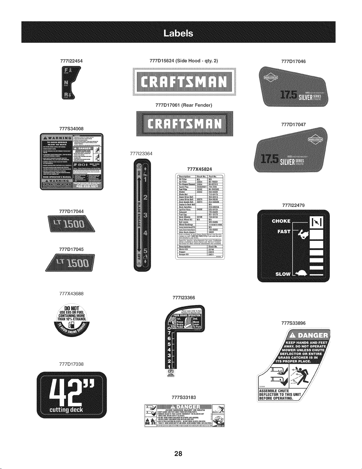
777122454 777D15624 (Side Hood - qty. 2) 777D17046
777D17061 (Rear Fender)
777S34008
777D17047
777123364
777D17044
777D17045
777X45824
777122479
777X43688
DOHOT...........
USE E85 UR FUEL
CO_TA|IIIHG _ORE
THAH 10% ETHANOL
W
777D17038
777123366
i(@)!
777S33183
_111!!11111111111_[_:___
......................N
777S33896
28

This page intentionally left blank. Use this page to make any notes regarding your tractor.
29
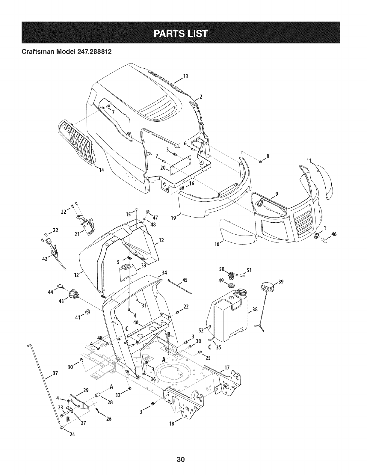
Craftsman Model 247.288812
19
12
22
17
1
46
b f
3O

Craftsman Model 247.288812
Ref. I
No,
1 925-1649
2 683-04619A-4043
3 710-04484
4 710-0599
5 712-0292
6 710-0751
7 710-05108
8 712-04064
9 931-07668
10 731-07458
11 731-07459
12 731-07460A
13 731-07711A
14 731-07712A
15 735-0271A
16 738-04091A
17 783-05327B-0637
18 783-05328A-0637
19 783-06598-4043
20 783-06610-0637
21 983-04503
22 710-05070
23 710-3144
24 711-0736
25 712-04065
26 714-04040
27 783-06823
Part No. Description
BulbSocket
HoodAssembly
Screw,5/16-18x .750
HexWasherScrew,1/4-20x .500
Tin Clip Nut, 1/4-20
HexScrew,1/4-20x .620
Screw,1/4 x .750
Nut,HexFlangeInsertLock,1/4-20
Grill
HeadlightLens,RH
HeadlightLens,LH
DashCollar
HoodScoop,LH
HoodScoop,RH
Bumper
ShoulderScrew,5/16-18
LeftSupportPivotBracket
RightSupportPivotBracket
LowerGrill
LowerGrill Bracket
SpeedSelector,7-Speed
Self-TapScrew,1/4-20
HexHeadScrew,3/8-16
Ferrule,1/4-20x 1.00
Nut,HexFlangeInsertLock,3/8-16
Cotter Pin
SpeedLatchSupportTab
Ref. I
No,
28 750-04465C
29 783-04903
30 710-0604A
31 710-05108
32 712-04063
33 731-04945
34 783-04873B-0637
35 747-05371
36 747-05326
37 747-04430
38 951-04304
39 951-12179A
40 783-07083-0637
41 731-05265
42 746-04364
43 925-04659
44 625-04124
45 725-0157
46 925-0963
47 726-04072A
48 936-0463
49 735-04081
50 751-12118
51 751-12089
52 710-1652
-- 777X44366
-- 777X44365
Part No. Description
FlangeSpacer
Speedlatch
Self-TapScrew,5/16-18
HexScrew,1/4x .750
Nut, HexFlangeLock,5/16-18
SteeringSupport
Dash
FuelTankSupport Rod
Dashsupport Rod
SpeedSelectorControl Rod
1.36GallonFuelTank
FuelCap
GasTankSupport Bracket
ChokePlug
Throttle/ChokeAssembly
KeySwitchModule
Key(2 pack)
CableTie
HeadlightBulb
RatchetClip: .250x .500
FlatWasher,.25x .630x .0515
RubberGrommet
FuelRolloverValve
VentHose
Hex Washer Screw, 1/4-20 x .625
Headlight Reflector LH (NotShown)
Headlight Reflector RH(NotShown)
31
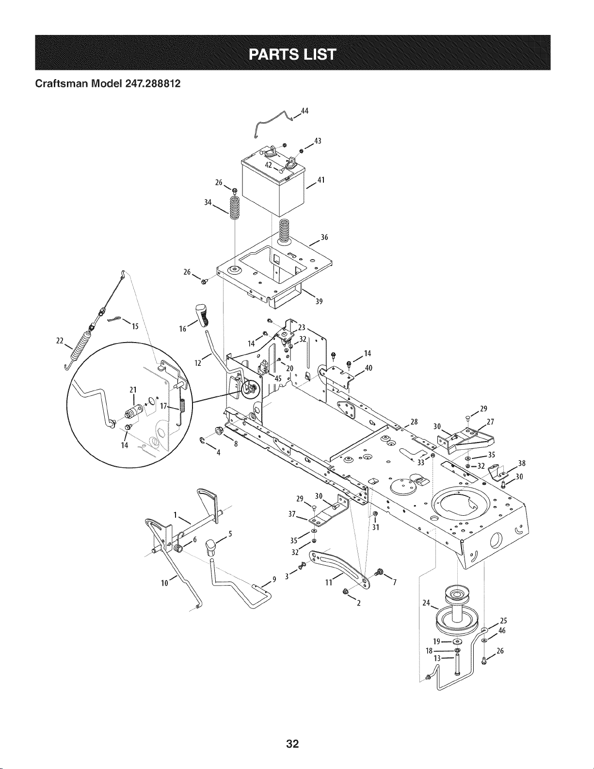
Craftsman Model 247.288812
26
34
22
21
14
12
39
i31
2
_29
? 27
32
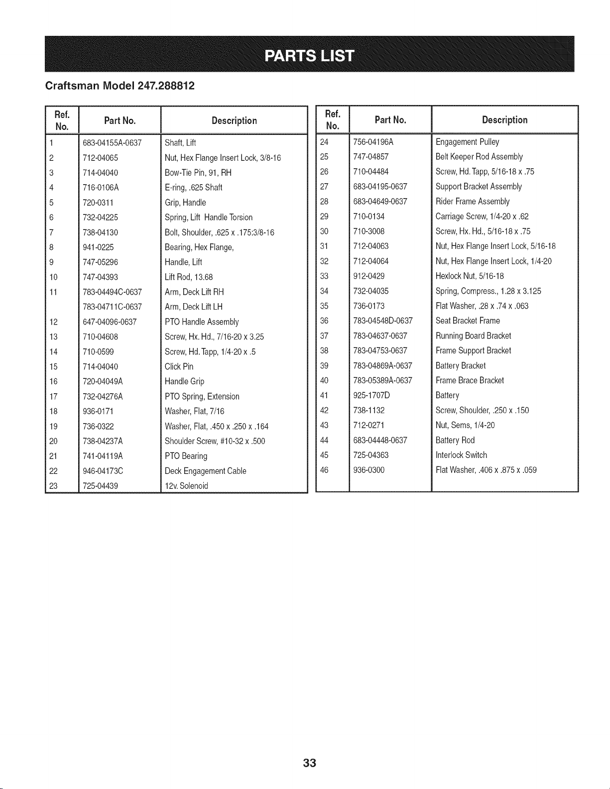
Craftsman IViodel 247.288812
Ref. I
No.
1 683-04155A-0637
2 712-04065
3 714-04040
4 716-0106A
5 720-0311
6 732-04225
7 738-04130
8 941-0225
9 747-05296
10 747-04393
11 783-04494C-0637
783-04711C-0637
12 647-04096-0637
13 710-04608
14 710-0599
15 714-04040
16 720-04049A
17 732-04276A
18 936-0171
19 736-0322
20 738-04237A
21 741-04119A
22 946-04173C
23 725-04439
Part No. Description
Shaft, Lift
Nut, HexFlangeInsertLock,3/8-16
Bow-TiePin,91, RH
E-ring,.625Shaft
Grip,Handle
Spring,Lift HandleTorsion
Bolt, Shoulder,.625x .175:3/8-16
Bearing,HexFlange,
Handle,Lift
Lift Rod,13.68
Arm, DeckLift RH
Arm, DeckLift LH
PTOHandleAssembly
Screw,Hx. Hd.,7/16-20x 3.25
Screw,Hd.Tapp,1/4-20x .5
Click Pin
HandleGrip
PTOSpring,Extension
Washer,Flat,7/16
Washer,Fiat, .450x .250x .164
ShoulderScrew,#10-32x .500
PTOBearing
DeckEngagementCable
12v.Solenoid
Ref. I
No.
24 756-04196A
25 747-04857
26 710-04484
27 683-04195-0637
28 683-04649-0637
29 710-0134
30 710-3008
31 712-04063
32 712-04064
33 912-0429
34 732-04035
35 736-0173
36 783-04548D-0637
37 783-04637-0637
38 783-04753-0637
39 783-04869A-0637
40 783-05389A-0637
41 925-1707D
42 738-1132
43 712-0271
44 683-04448-0637
45 725-04363
46 936-0300
Part No. Description
EngagementPulley
Belt KeeperRodAssembly
Screw,Hd.Tapp,5/16-18x .75
SupportBracketAssembly
RiderFrameAssembly
CarriageScrew,1/4-20x .62
Screw,Hx. Hd.,5/16-18x .75
Nut, HexFlangeInsert Lock,5/16-18
Nut, HexFlangeInsert Lock,1/4-20
HexlockNut,5/16-18
Spring,Compress.,1.28x 3.125
FlatWasher,.28x .74x .063
SeatBracketFrame
RunningBoardBracket
FrameSupportBracket
BatteryBracket
FrameBraceBracket
Battery
Screw,Shoulder,.250x .150
Nut,Sems, 1/4-20
BatteryRod
InterlockSwitch
FlatWasher,.406x .875x .059
33
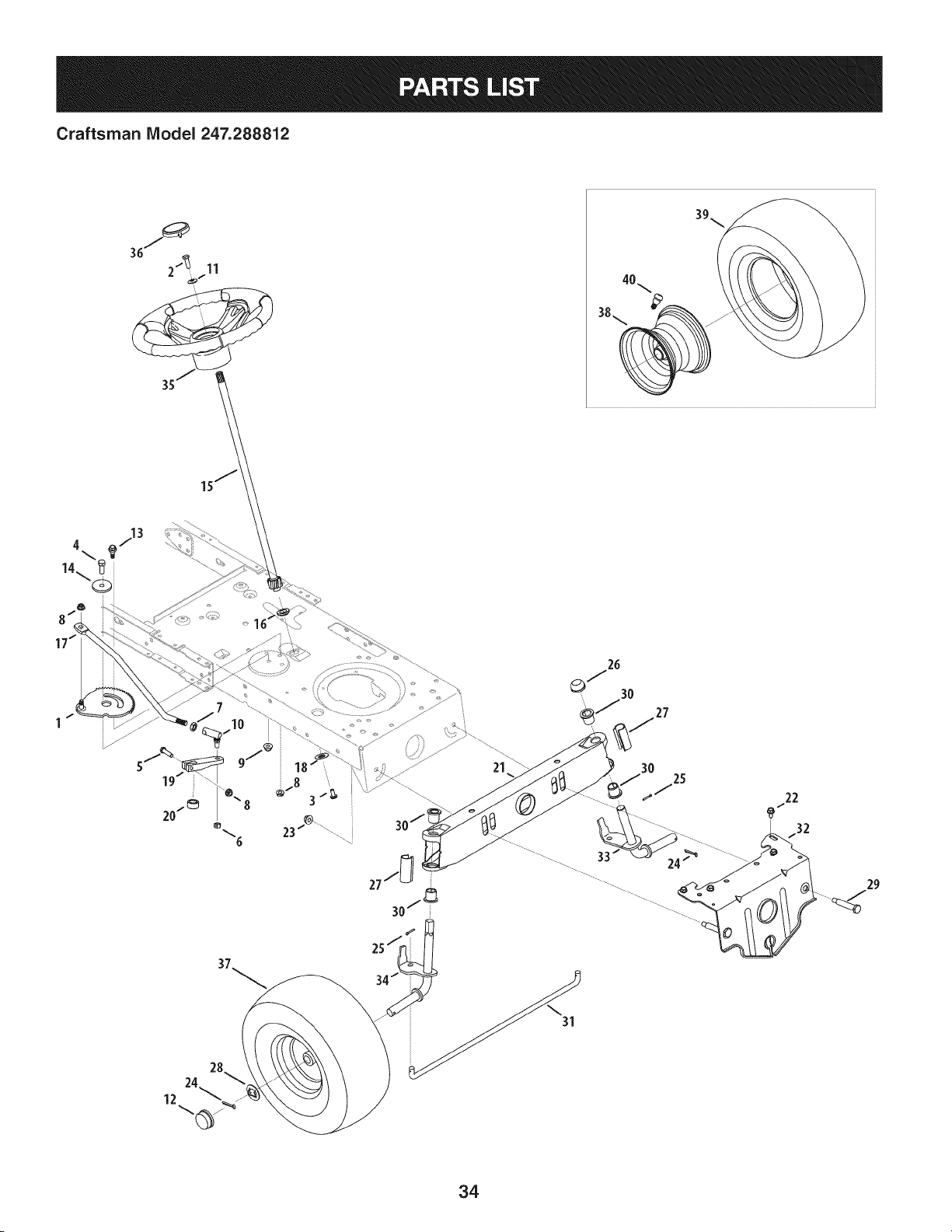
Craftsman Model 247.288812
21
3O
25
22
................ 33 / /_ ........................
34
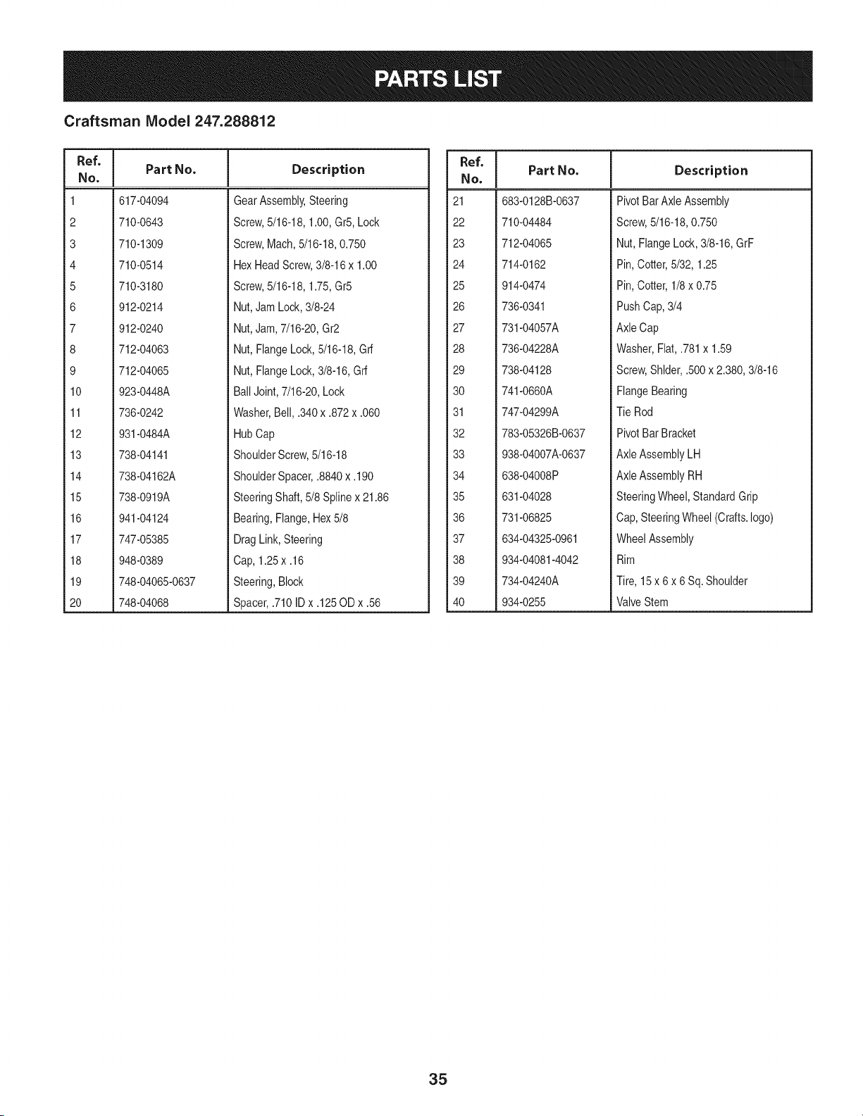
Craftsman IViodel 247.288812
Ref, I
No.
1 617-04094
2 710-0643
3 710-1309
4 710-0514
5 710-3180
6 912-0214
7 912-0240
8 712-04063
9 712-04065
10 923-0448A
11 736-0242
12 931-0484A
13 738-04141
14 738-04162A
15 738-0919A
16 941-04124
17 747-05385
18 948-0389
19 748-04065-0637
20 748-04068
Part No. Description
GearAssembly,Steering
Screw,5/16-18,1.00,Gr5,Lock
Screw,Mach,5/16-18,0.750
HexHeadScrew,3/8-16x 1.00
Screw,5/16-18,1.75,Gr5
Nut,JamLock,3/8-24
Nut,Jam,7/16-20,Gr2
Nut,FlangeLock,5/16-18,Grf
Nut,FlangeLock,3/8-16,Grf
BallJoint,7/16-20,Lock
Washer,Bell, .340x .872x .060
HubCap
ShoulderScrew,5/16-18
ShoulderSpacer,.8840x.190
SteeringShaft,5/8 Splinex 21.86
Bearing,Flange,Hex5/8
DragLink,Steering
Cap, 1.25x .16
Steering,Block
Spacer,.710ID x .125OD x .56
Ref, I
No.
21 683-0128B-0637
22 710-04484
23 712-04065
24 714-0162
25 914-0474
26 736-0341
27 731-04057A
28 736-04228A
29 738-04128
30 741-0660A
31 747-04299A
32 783-05326B-0637
33 938-04007A-0637
34 638-04008P
35 631-04028
36 731-06825
37 634-04325-0961
38 934-04081-4042
39 734-04240A
40 934-0255
Part No, Description
PivotBarAxle Assembly
Screw,5/16-18,0.750
Nut, FlangeLock,3/8-16,GrF
Pin, Cotter,5/32, 1.25
Pin, Cotter,1/8 x 0.75
PushCap,3/4
AxleCap
Washer,Flat,.781x 1.59
Screw,Shlder,.500x 2.380,3/8-16
FlangeBearing
Tie Rod
PivotBar Bracket
AxleAssemblyLH
AxleAssemblyRH
SteeringWheel,StandardGrip
Cap,SteeringWheel (Crafts.logo)
WheelAssembly
Rim
Tire, 15 x 6 x 6 Sq.Shoulder
ValveStem
35
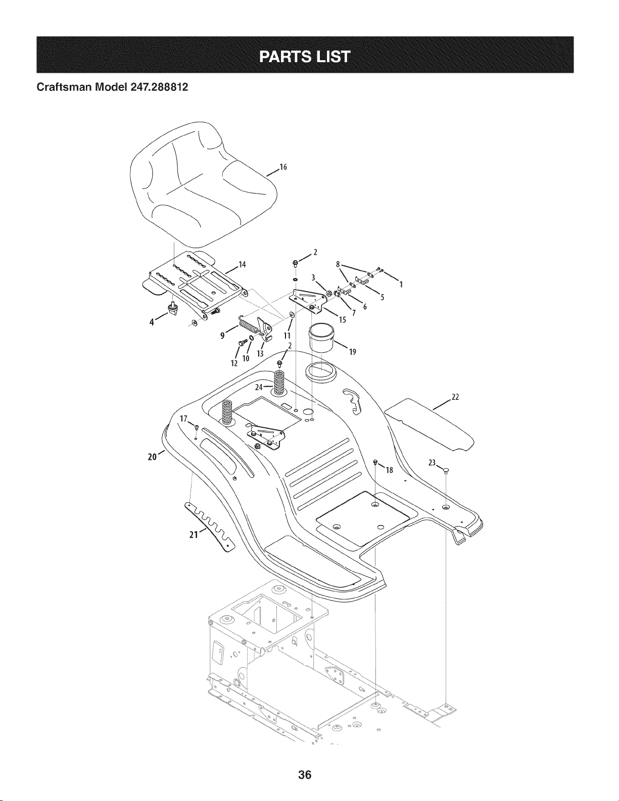
Craftsman IViodel 247.288812
\
\
36
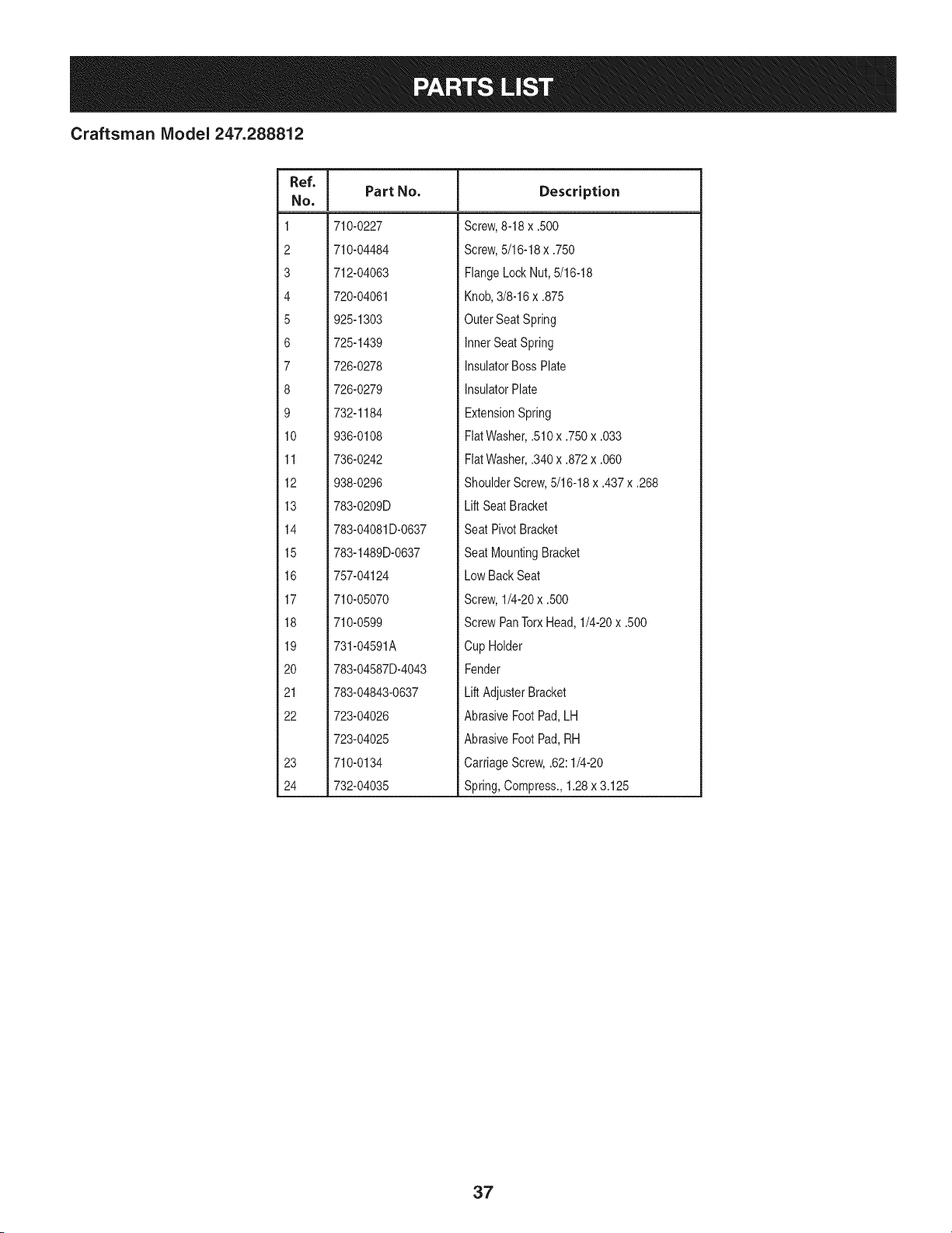
Craftsman IViodel 247.288812
Ref. I
No,
1 710-0227
2 710-04484
3 712-04063
4 720-04061
5 925-1303
6 725-1439
7 726-0278
8 726-0279
9 732-1184
10 936-0108
11 736-0242
12 938-0296
13 783-0209D
14 783-04081D-0637
15 783-1489D-0637
16 757-04124
17 710-05070
18 710-0599
19 731-04591A
20 783-04587D-4043
21 783-04843-0637
22 723-04026
723-04025
23 710-0134
24 732-04035
Part No. Description
Screw,8-18 x .500
Screw,5/16-18x .750
FlangeLockNut, 5/16-18
Knob,3/8-16x .875
OuterSeat Spring
InnerSeatSpring
InsulatorBossPlate
InsulatorPlate
ExtensionSpring
FiatWasher,.510x .750x .033
FlatWasher,.340x .872x .060
ShoulderScrew,5/16-18x .437x .268
Lift SeatBracket
Seat PivotBracket
Seat MountingBracket
Low BackSeat
Screw,1/4-20x .500
ScrewPanTorxHead,1/4-20x .500
Cup Holder
Fender
Lift AdjusterBracket
AbrasiveFootPad,LH
AbrasiveFootPad,RH
CarriageScrew,.62:1/4-20
Spring,Compress.,1.28x 3.125
37
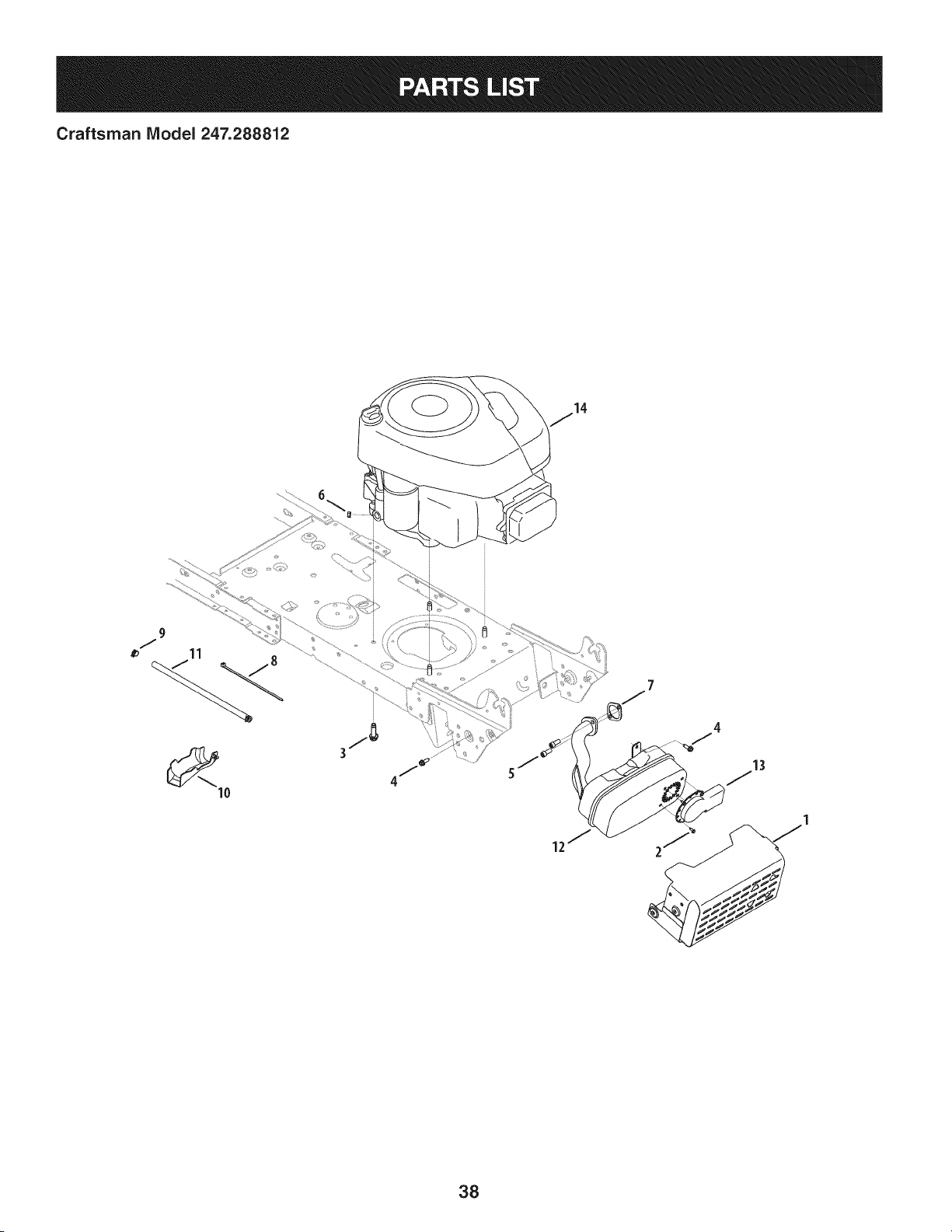
Craftsman IViodel 247.288812
38
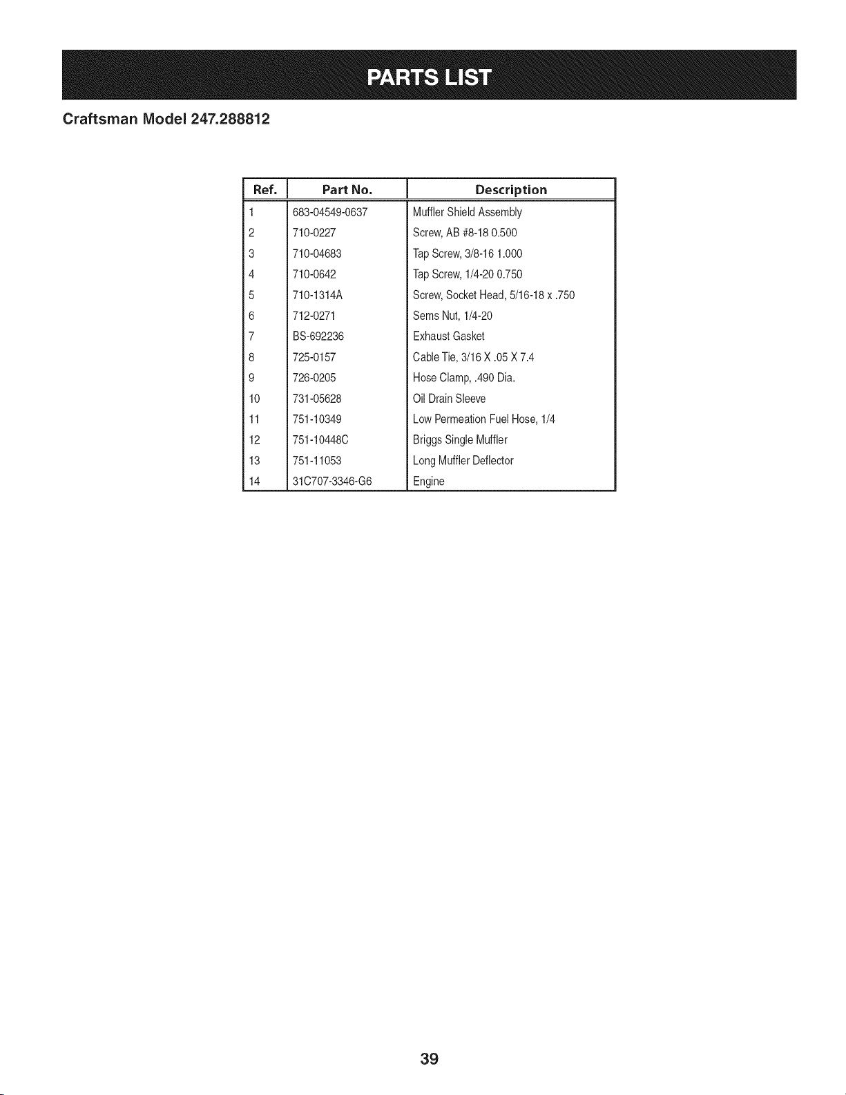
Craftsman IViodel 247.288812
I
Ref. I Part No.
1 683-04549-0637
2 710-0227
3 710-04683
4 710-0642
5 710-1314A
6 712-0271
7 BS-692236
8 725-0157
9 726-0205
10 731-05628
11 751-10349
12 751-10448C
13 751-11053
14 31C707-3346-G6
Description
MufflerShieldAssembly
Screw,AB #8-180.500
TapScrew,3/8-16 1.000
TapScrew,1/4-200.750
Screw,SocketHead,5/16-18x .750
Sems Nut, 1/4-20
ExhaustGasket
CableTie,3/16 X .05 X 7.4
HoseClamp,.490 Dia.
Oil DrainSleeve
LowPermeationFuelHose,1/4
BriggsSingleMuffler
LongMufflerDeflector
Engine
39
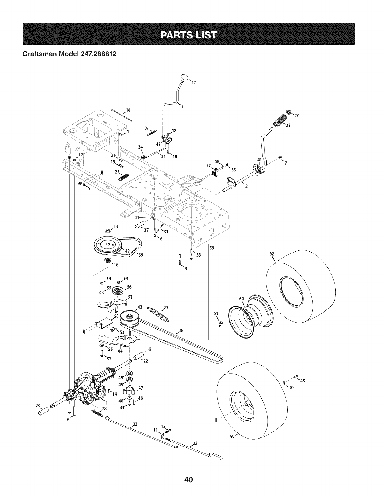
Craftsman IViodel 247.288812
18
8
27
38
6O
62
\
23
1 15
4O

Craftsman IViodel 247.288812
Ref, I
NO,
1 918-04566
2 647-04034C-0637
3 647-04266
4 710-0227
5 710-04484
6 710-0599
7 710-0604A
8 710-0809
9 710-0176
10 710-3008
11 911-04075A
12 712-04063
13 712-0700
14 914-0209
15 714-04040
16 718-04407
17 720-04028
18 725-0157
19 725-1644
20 726-0214
21 926-0320
22 731-04602
23 731-04604
24 731-06894
25 732-04306
26 732-04488
27 732-04746
28 732-0716D
29 735-0239
30 736-0242
31 747-04969
32 747-05186
Part No. Description
TransmissionDriveAssembly
PedalAssembly
Shaft LeverAssembly
Screw,8-18:0.500
Screw,5/16-18x .750
Screw,1/4-20x 0.500
Screw,5/16-18x 0.625
Screw,1/4-20x 1.250
HexScrew,5/16-18x 2.75
HexScrew,5/16-18x .75
Ferrule,3/8-24X .375DIA.
FlangelockNut, 5/16-18
FlangeNut, 9/16-18
Cotter Pin INT-.125DIA
Bow-TieCotter Pin
PulleyHub,5/8SPLINE
Shift Knob
CableTie
Short SpringSwitch
PushCap,5/8
PlateInsulatorNut
Sleeve,.758x .821x 3.3125
Sleeve,.758x .821x 2.4375
Shift BearingPlate
SpringExtension,.80ODx 3.28LG
SpringExtension,.38ODx 3.25LG
SpringExtension,.94ODx 6.75LG
SpringExtension,.59ODx 4.00LG
FootPad,4.0 LONG
BellWasher,.340x .872x .060
Belt KeeperRod
VariableSpeedControl Rod
Ref. I
No,
33 747-05188
34 747-05244
35 738-04237A
36 750-0566A
37 750-0802
38 954-04249A
39 954-0241A
40 956-04002
41 783-04536B-0637
42 783-04595A
43 956-04015A
44 683-04206
45 710-0627
46 710-0778
47 718-04261
48 736-0362
49 941-0600
50 683-04176A
51 683-04207
52 710-0347
53 710-1260A
54 712-04065
55 938-0347
56 756-04325
57 725-04363
58 17962
59 634-04324
60 634-04369-4042
61 934-0255
62 734-04241
-- 725-04567G
Part No. Description
BrakeRod
Shift Rod
ShoulderScrew,#10-32x .500
Spacer,.260 x .375x 1.030LG
Spacer,.640 ID x .76ODx 2.63
V Belt, 5L:70.90 POLY
V Belt, 5L:35.25 POLY
Trans.Pulley
PedalSupportBracket
ShaftAdjustBracket
VariableSpeed PulleyAssembly
BracketAssembly
HexScrew,5/16-24x .750
Screw,1/4-20x 1.500
BearingCup
FlatWasher,.330x 1.25x .06:HT
Ball Bearing,17x 40x 12
TransmissionBracketAssembly
Idler BracketAssembly
HexScrew,3/8-16x 1.75
Screw,5/16-18x 0.750
FlangeLockNut, 3/8-16
ShoulderSpacer,.625ID x .169
Idler Pulley
SwitchInterlock
PlateSwitch
WheelAssembly,20 x 8 x 8
RimAssembly
ValveStem
Tire, 20 x 8 x 8 Rd.Sh.
WiringHarness(Not Shown)
41
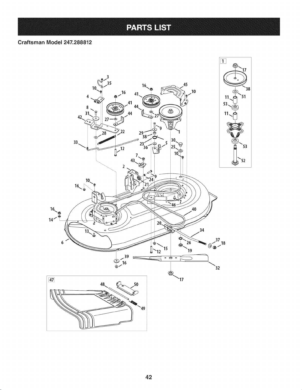
Craftsman IViodel 247.288812
12
45
10
J
[]
11
53\_
11_
2
4O
37
@_/18
32
42

Craftsman IViodel 247.288812
Ref, I
No,
1 918-04822A
2 683-0254B-0637
3 710-0642
4 983-04511
5 983-04525
6 983-04570-0637
7 710-04484
8 710-3005
9 710-0528
10 710-0599
11 750-04936
12 710-3144
13 710-3178
14 712-0229
15 712-04063
16 712-04065
17 712-0417A
18 712-04243
19 912-0641
20 714-04043
21 917-04074
22 932-0384
23 732-04840
24 936-0119
25 736-0187
26 736-0225
27 736-0262
Part No. Description
SpindlePulleyAssembly
DeckHangerBracketAssembly
Screw,1/4-20x .750
BrakeAssembly
BrakeAssembly
Deck
Screw,5/16-18x .750
Screw,3/8-16x 1.25
HexScrew,5/16-18 x 1.25
Screw,1/4-20x .500
Spacer,.792x 1.060x 1.860
HexHeadScrew,3/8-16
CarriageBolt, 3/8-16x .75
PushNut,3/8
FlangelockNut, 5/16-18
FlangelockNut, 3/8-16
FlangeNut, 5/8-18
FlangelockNut, 1/2-13
HexNut,M16- 1.5
CotterPin, Bow-Tie
DeckAdjusterGear
ExtensionSpring,.62x 6.12
TorsionSpring,1.0 x 1.17
LockWasher,5/16
FiatWasher,.64x 1.24x .06
FlatWasher,.5/8Int.Tth.
FiatWasher,.385x .870x .092
Ref. I
NO,
28 936-0344
29 736-0362
30 738-04146
31 738-04162A
32 942-04308
33 747-05105B
34 747-05141A
35 747-05323
36 748-04272
37 748-04069
38 956-1227
39 936-3039
40 954-04060B
41 756-04129B
42 783-05946
43 783-06243-0637
44 783-06368A-0637
45 783-06424A-0637
46 783-06643-0637
47 631-04288
48 711-04847B
49 732-04372
50 783-06074A
51 936-0351
52 738-1186A
53 941-0919A
Part No. Description
FlatWasher,.385x 1.0x .030
FlatWasher,.330x 1.25x .06
Bolt Plug,M16x 1.5
ShoulderSpacer,.8840x .190
CuttingBlade,21.23":2 in 1
BrakeControlRod
DeckLift Rod
Belt KeeperRod
ShoulderSpacer
DeckLift PivotCup
DeckPulley,6.3dia.
FlatWasher,.406x 1.50x .105
V-TypeBelt, 96.5
Idler Pulley,4.25Diameter
Idler PivotBracket
DeckCableEngagementBracket
Belt PulleyGuard
DeckBelt Cover
DeckSupportBracket
ChuteDeflectorAssembly
Hinge Pin
TorsionSpring,.44x 2.0
ChuteBracket
FlatWasher,.760x 1.50
SpindleShaft
Ball Bearing,.787x 1.85x .551
43
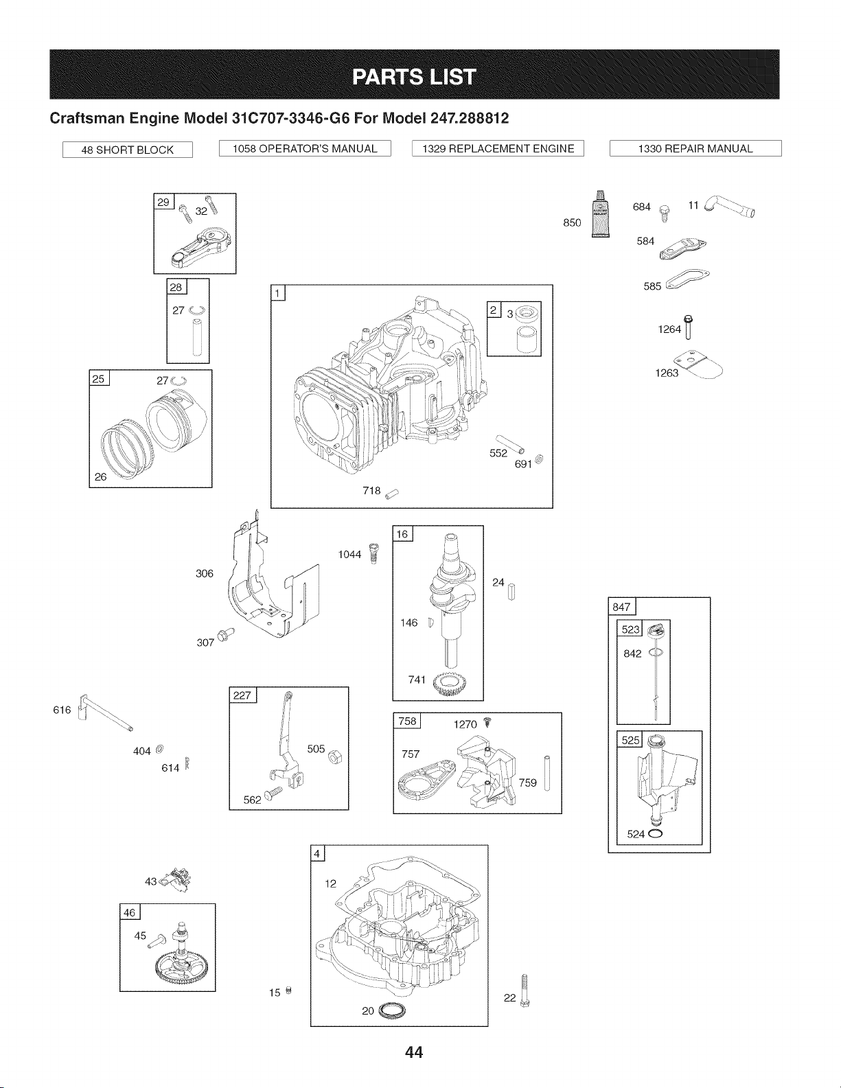
Craftsman Engine IViodel 310707-3346-G6 For IViodel 247.288812
48 SHORT BLOCK 1058 OPERATOR'S MANUAL [ 1329 REPLACEMENT ENGINE ] 1330 REPAIR MANUAL
616
27
404 (_
614
q
_J3 _-_,Z;/
k.'-. _)
718
j ' 1044 I_
306
[ 741
20C_
24 _
#i
;i
f
562 _:_ _
505
127o
759
46 _::_
45 :/:__
15 e
22
85O
684 _f# 11 _ ......"-_i,'}
584
585 _
1264 _
\\ ,
842 QiD
U
5240
44
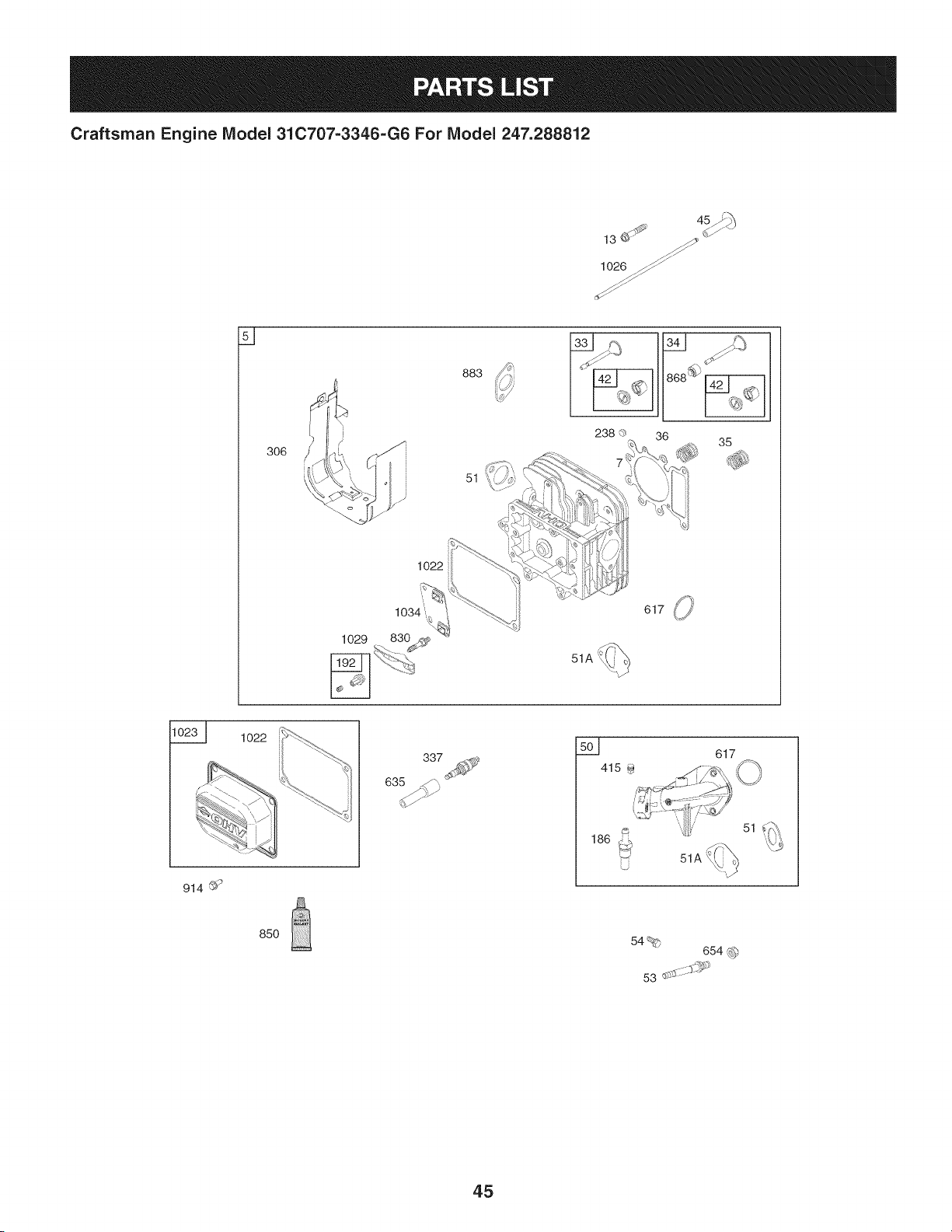
Craftsman Engine Model 31C707-3346-G6 For Model 247.288812
lO26_/_
s _
883
51
35
1022
1o22
337
501
617
914 ©'9
85O
54%
654 _)
53 d:*-;_::::$S'i_
45
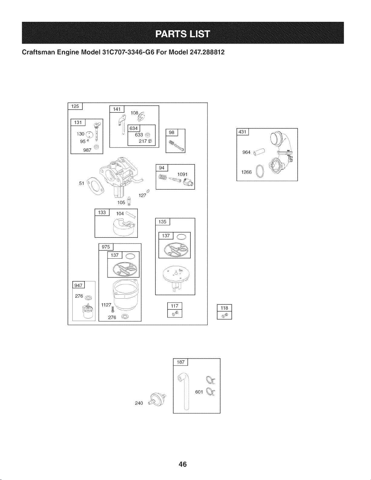
Craftsman Engine IViodel 31C707-3346-G6 For IViodel 247.288812
130 :-'_
95 _ _
987
_ lO_
i
633 _
2179
51
105
Q
127
1127__
276 _)
1091
964 ........
' i
24O
6Ol _
i
46
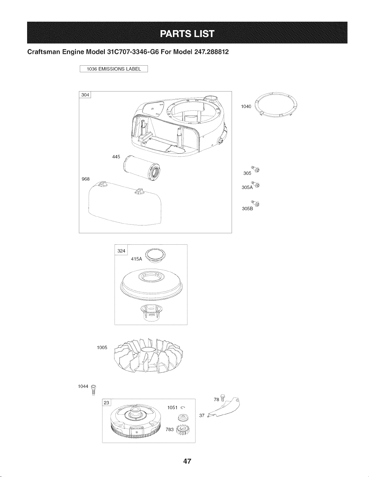
Craftsman Engine Model 31C707=3346=G6 For Model 247.288812
1036 EMiSSiONS LABEL
968
445
\\
I
2
1040
305 _
305AQ_
305B
324
415A
,./:,,;\ \"_{,":,_j !/ 4_7><_
lOOS C-;>..._\\d_-_t ib.j,:Q _
1044
78 b_ d_
37 _
47
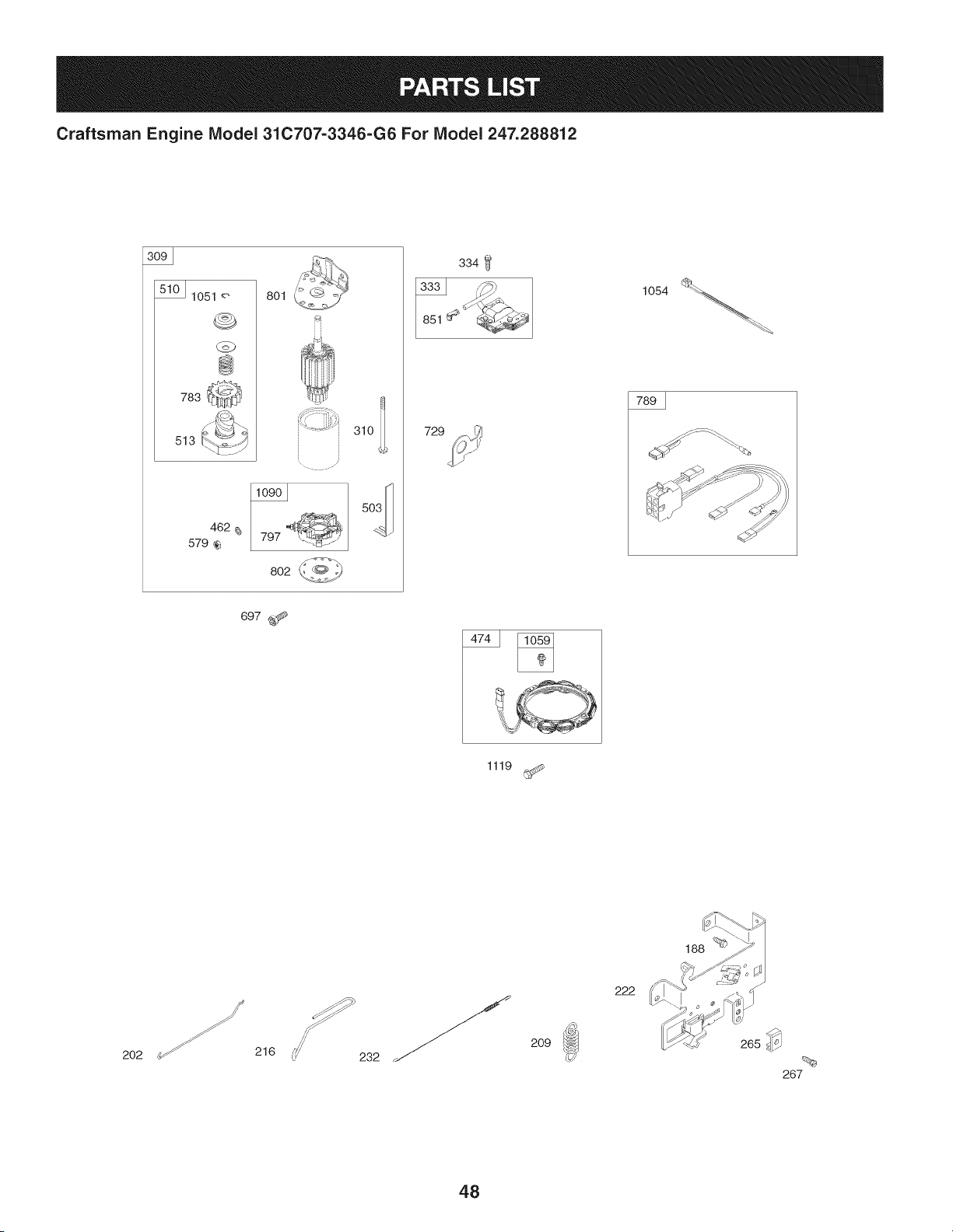
Craftsman Engine IViodel 31C707-3346-G6 For IViodel 247.288812
lO51 8ol
@
783
513
462
579
. i '¸
797
802
729
334
697 _
1119
188 _
202
216
232
209
222
48
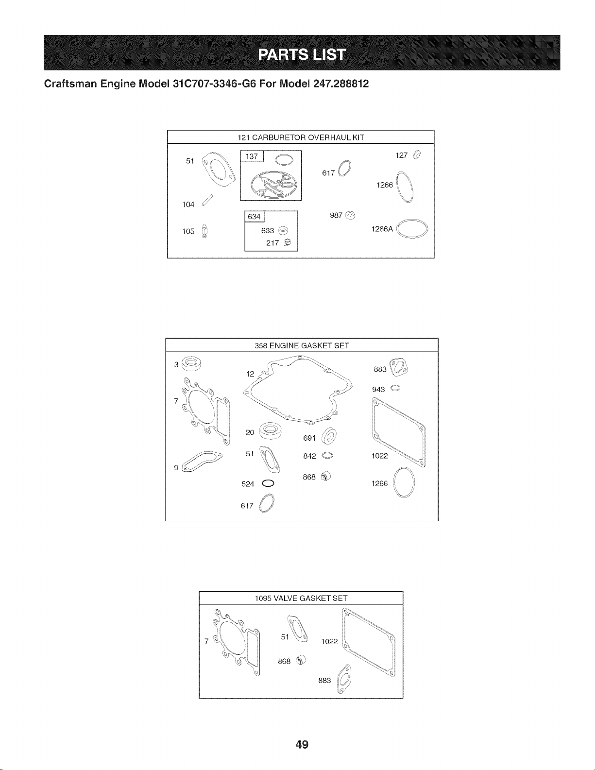
Craftsman Engine IViodel 31C707-3346-G6 For IViodel 247.288812
51
104
105
121 CARBURETOR OVERHAUL KiT
O 127 _
617,, ifX,
1266 :, '_,
33 _'_
217
987_/
1266A
/';/ .>_,
3 _<J/
358 ENGINE GASKET SET
12
_i / JJ
883
943 O
2O
51
524
O
691
842 g
868 %_9
1O22
1266 ((
617
1095 VALVE GASKET SET
51
868
1o22
883
49

Craftsman Engine IViodel 31C707=3346=G6 For IViodel 247.288812
Ref.
No,
1 796010
2 399265
3 391086s
4 697106
5 796026
7 796584
11 794683
12 697110
13 793988
15 690946
16 797579
20 795387
22 692125
23 698281
24 796335
25 796172
796173
26 791936
792649
27 698469
28 796007
29 794122
32 791118
33 792868
34 791935
35 691279
36 691279
37 697352
42 499586
43 691968
45 690564
46 793880
48 697761
50 796180
51 692137
51A 796081
53 690227
54 691148
78 691693
94 793610
95 690718
98 695408
Part No. Description
CylinderAssembly
Bushing/SealKit (MagnetoSide)
Seal-Oil (MagnetoSide)
Sump-Engine
Head-Cylinder
Gasket-CylinderHead
Tube-Breather
Gasket-Crankcase
Screw(Cylinder Head)
Plug-OilDrain
Crankshaft
Seal-Oil (PTOSide)
Screw(CrankcaseCover/Sump)
Flywheel
Key-Flywheel(Steel)
PistonAssembly(Standard)
PistonAssembly(.020"Oversize)
RingSet (Standard)
RingSet (.020" Oversize)
Lock-PistonPin
Pin-Piston
Rod-Connecting
Screw(ConnectingRod)
Valve-Exhaust
Valve-Intake
Spring-Valve(Intake)
Spring-Valve(Exhaust)
Guard-Flywheel
Keeper-Valve
Slinger-Governor/Oil
Tappet-Valve
Gear-Cam
Short Block
Manifold-Intake
Gasket-Intake
Gasket-Intake
Stud (Carburetor)
Screw(IntakeManifold)
Screw(FlywheelGuard)
KiNdle Mixture
Screw(ThrottleValve)
KiNdle Speed
50
I
Ref.
I Part No,
No,
I
104 694918
105 696136
108 695419
117 843099
118 790890
121 796184
125 796109
127 690727
130 699500
131 699501
133 694914
135 698780
137 698781
141 792777
146 691639
186 794873
187 791805
188 691693
192 691986
202 691841
209 692208
216 691840
217 695409
222 694042
227 691374
232 691842
238 691843
240 394358s
265 691024
267 794904
276 695410
304 797900
305 697102
305A 793376
305B 795891
306 796006
307 691693
309 693551
Description
Pin-FloatHinge
Valve-FloatNeedle
Valve-Choke
Jet-Main(Standard)
Jet-Main(HighAltitude)
Kit-CarburetorOverhaul
Carburetor
Plug-Welch
Valve-Throttle
Kit-ThrottleShaft
Float-Carburetor
Tube-FuelTransfer
Gasket-FloatBowl
Kit-ChokeShaft
Key-Timing
Connector-Hose(intake Manifold)
Line-Fuel(Formed)(Cutto RequiredLength)
Screw(ControlBracket)
Adjuster-RockerArm
Link-MechanicalGovernor
Spring-Governor(Green)
Link-Choke
Spring-ChokeReturn
Bracket-Control
Lever-GovernorControl
Spring-GovernorLink
Cap-Valve
Filter-Fuel
Clamp-Casing
Screw(CasingClamp)
Washer-Sealing
BlowerHousing
Screw(BlowerHousing)(1/4-20x1.14)
Screw(BlowerHousing)(1/4-20x.68)
Screw(BlowerHousing)(10-16x.43)
Shield-Cylinder
Screw(CylinderShield)
Motor-Starter
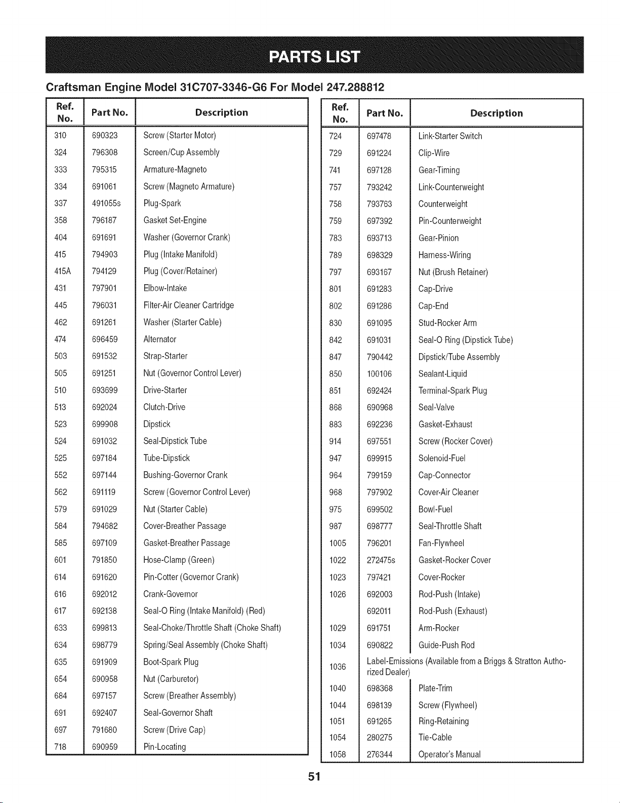
Craftsman Engine IViodel 31C707=3346=G6 For IViodel
I
Ref.
I Part No.
No,
I
310 690323
324 796308
333 795315
334 691061
337 491055s
358 796187
404 691691
415 794903
415A 794129
431 797901
445 796031
462 691261
474 696459
503 691532
505 691251
510 693699
513 692024
523 699908
524 691032
525 697184
552 697144
562 691119
579 691029
584 794682
585 697109
601 791850
614 691620
616 692012
617 692138
633 699813
634 698779
635 691909
654 690958
684 697157
691 692407
697 791680
718 690959
Description
Screw(Starter Motor)
Screen/CupAssembly
Armature-Magneto
Screw(MagnetoArmature)
Plug-Spark
GasketSet-Engine
Washer(GovernorCrank)
Plug(intakeManifold)
Plug(Cover/Retainer)
Elbow-intake
Filter-AirCleanerCartridge
Washer(StarterCable)
Alternator
Strap-Starter
Nut(GovernorControlLever)
Drive-Starter
Clutch-Drive
Dipstick
Seal-DipstickTube
Tube-Dipstick
Bushing-GovernorCrank
Screw(GovernorControlLever)
Nut(StarterCable)
Cover-BreatherPassage
Gasket-BreatherPassage
Hose-Clamp(Green)
Pin-Cotter(GovernorCrank)
Crank-Governor
SeaI-ORing (IntakeManifold)(Red)
Seal-Choke/ThrottleShaft (ChokeShaft)
Spring/SealAssembly(ChokeShaft)
Boot-SparkPlug
Nut(Carburetor)
Screw(BreatherAssembly)
Seal-GovernorShaft
Screw(DriveCap)
Pin-Locating
51
247.288812
Ref.
No,
724 697478
729 691224
741 697128
757 793242
758 793763
759 697392
783 693713
789 698329
797 693167
801 691283
802 691286
830 691095
842 691031
847 790442
850 100106
851 692424
868 690968
883 692236
914 697551
947 699915
964 799159
968 797902
975 699502
987 698777
1005 796201
1022 272475s
1023 797421
1026 692003
692011
1029 691751
1034 690822
1036
1040
1044
1051
1054
1058
Part No, Description
Link-StarterSwitch
Clip-Wire
Gear-Timing
Link-Counterweight
Counterweight
Pin-Counterweight
Gear-Pinion
Harness-Wiring
Nut (BrushRetainer)
Cap-Drive
Cap-End
Stud-RockerArm
SeaI-ORing(DipstickTube)
Dipstick/TubeAssembly
Sealant-Liquid
Terminal-SparkPlug
Seal-Valve
Gasket-Exhaust
Screw(RockerCover)
Solenoid-Fuel
Cap-Connector
Cover-AirCleaner
Bowl-Fuel
Seal-ThrottleShaft
Fan-Flywheel
Gasket-RockerCover
Cover-Rocker
Rod-Push(Intake)
Rod-Push(Exhaust)
Arm-Rocker
Guide-PushRod
Label-Emissions(Availablefroma Briggs& StrattonAutho-
rized Dealer)
698368
698139
691265
280275
276344
Plate-Trim
Screw(Flywheel)
Ring-Retaining
Tie-Cable
Operator'sManual

Craftsman Engine IViodel 31C707=3346=G6 For IViodel 247.288812
Ref, I
NO,
1059 698516
1090 691293
1091 691333
1095 794152
1119 691183
1127 695407
1263 697124
1264 697104
1266 691917
1266A 697123
1267 697419
1270 793243
31C707-
1329 3346-G2/
G6
1330 272147
Part No. Description
Kit-Screw/Washer(Alternator)
Retainer-Brush
Cap-Limiter
GasketSet-Valve
Screw(Alternator)
Screw(FloatBowl)
Reed-Breather
Screw(BreatherReed)
Seal-O Ring (IntakeElbow)(Red)
Seal-O Ring (IntakeElbow)
Latch-BlowerHousing
Plug-AVSCounterweight
ReplacementEngine
RepairManual
EngineGasketSet
Valve GasketSet
CarburetorOverhaulKit
KeyNo. 358
KeyNo. 1095
KeyNo. 121
52
Look For Relevant Emissions Durability Period and
Air index information On Your Engine Emissions Label
Engines that are certified to meet the California Air Resources Board (CARB) Tier 2 Emission Standards must
display information regarding the Emissions Durability Period and the Air Index. Sears Brands Management
Corporation makes this information available to the consumer on our emission labels.
The Emissions Durability Period describes the number of hours of actual running time for which the engine is
certified to be emissions compliant, assuming proper maintenance in accordance with the Operating & Mainte-
nance Instructions. The following categories are used:
Moderate: Engine is certified to be emission compliant for 125 hours of actual engine running time.
Intermediate: Engine is certified to be emission compliant for 250 hours of actual engine running time.
Extended: Engine is certified to be emission compliant for 500 hours of actual engine running time.
For example, a typical walk-behind lawn mower is used 20 to 25 hours per year. Therefore, the Emissions
Durability Period of an engine with an intermediate rating would equate to 10 to 12 years.
The Air index is a calculated number describing the relative level of emissions for a specific engine family. The
lower the Air Index, the cleaner the engine. This information is displayed in graphical form on the emissions label.
After July 1,2000, Look For Emissions Compliance Period
On Engine Emissions Compliance Label
After July 1, 2000 certain Sears Brands Management Corporation engines will be certified to meet the United
States Environmental Protection Agency (USEPA) Phase 2 emission standards. For Phase 2 certified engines, the
Emissions Compliance Period referred to on the Emissions Compliance label indicates the number of operating
hours for which the engine has been shown to meet Federal emission requirements.
For engines less than 225 cc displacement, Category C = 125 hours, B = 250 hours and A = 500 hours.
For engines of 225 cc or more, Category C = 250 hours, B = 500 hours and A = 1000 hours.
This is a generic representation of the emission label typically found on a certified engine.
FAMILYYBSXS.3192VA 274812
GDOC-100182Rev.B
53
(Thispageapplicablein the U.S.A.and Canadaonly.)
Sears Brands Management Corporation (Sears), the California Air Resources Board (CARD)
and the United States Environmental Protection Agency (U.S. EPA)
Emission Control System Warranty Statement (Owner's Defect Warranty Rights and Obligations)
EMISSIONCONTROLWARRANTYCOVERAGEISAPPLICABLETOCERTI-
FIEDENGINESPURCHASEDIN CALIFORNIAIN 1995ANDTHEREAF-
TER,WHICHARE USEDINCALIFORNIA,ANDTOCERTIFIEDMODEL
California and United States Emission
The CaliforniaAir ResourcesBoard(CARD),U.S.EPAand Searsare pleased
to explainthe EmissionControlSystemWarrantyon your modelyear2000and
latersmalloff-roadengine(SORE).In California,newsmall off-roadengines
mustbe designed,builtand equippedto meetthe State'sstringentanti-smog
standards.Elsewherein theUnitedStates, newnon-road,spark-ignition
enginescertifiedfor modelyear 1997and latermustmeetsimilarstandardsset
forth bythe U.S.EPA.Searsmustwarranttheemissioncontrol systemon your
YEAR 1997AND LATERENGINESWHICHARE PURCHASEDAND USED
ELSEWHEREIN THE UNITEDSTATES(ANDAFTERJANUARY1,2001 IN
CANADA).
Control Defects Warranty Statement
enginefor theperiodsoftime listedbelow,providedtherehas been noabuse,
neglector impropermaintenanceof your smalloff-roadengine.Youremis-
sion controlsystemincludespartssuch as thecarburetor,air cleaner,ignition
system,mufflerand catalyticconverter.Also includedmaybe connectorsand
otheremissionrelatedassemblies.Wherea warrantableconditionexists,Sears
will repairyour smalloff-roadengineat no costto you includingdiagnosis,parts
and labor.
Sears Emission Control Defects Warranty Coverage
Smalloff-roadenginesarewarrantedrelativeto emissioncontrolpartsdefects
fora periodof one year,subjectto provisionsset forth below.Ifany covered
Owner's Warranty
Asthe smalloff-roadengine owner,you are responsiblefor the performanceof
therequiredmaintenancelistedin yourOperatingand MaintenanceInstruc-
tions.Searsrecommendsthatyou retain all yourreceiptscoveringmaintenance
on yoursmalloff-roadengine,but Sears cannotdenywarrantysolelyfor the
lackof receiptsorfor yourfailureto ensuretheperformanceof allscheduled
maintenance.As the smalloff-roadengineowner,you shouldhoweverbe
awarethat Searsmay denyyou warrantycoverageifyour smalloff-roadengine
ora part hasfailed dueto abuse,neglect,impropermaintenanceor unap-
parton yourengineis defective,the part will be repairedorreplacedbySears.
Responsibilities
provedmodifications.Youare responsiblefor presentingyour smalloff-road
engineto an AuthorizedSearsServiceDealeras soonas a problemexists.The
undisputedwarrantyrepairsshouldbe completedina reasonableamountof
time,notto exceed30 days.Ifyou haveany questionsregardingyourwarranty
rightsand responsibilities,youshouldcontacta SearsService Representative
at 1-800-469-4663.The emissionwarrantyis a defectswarranty.Defectsare
judgedon normalengineperformance.The warrantyis notrelatedto an in-use
emissiontest.
Sears Emission Control Defects Warranty Provisions
ThefollowingarespecificprovisionsrelativetoyourEmissionControlDefectsWarrantyCoverage.Itisin additiontotheSearsenginewarrantyfornon-regulated
enginesfoundin the Operatingand MaintenanceInstructions.
1. WarrantedParts
Coverageunderthis warrantyextendsonly to the parts listedbelow (the
emissioncontrolsystemsparts)to the extentthese partswere presenton
theengine purchased.
a. FuelMeteringSystem
• Cold start enrichmentsystem
• Carburetorand internalparts
• FuelPump
b. Air lnduction System
• Air cleaner
• Intakemanifold
c. IgnitionSystem
• Spark plug(s)
• Magnetoignitionsystem
d. CatalystSystem
• Catalyticconverter
• Exhaustmanifold
• Air injectionsystemor pulsevalve
e. MiscellaneousItemsUsedin AboveSystems
• Vacuum,temperature,position,timesensitivevalves
andswitches
• Connectorsandassemblies
2. Lengthof Coverage
Searswarrantsto the initialownerand eachsubsequentpurchaserthat
theWarrantedPartsshallbefree from defects in materialsandworkman-
shipwhich causedthe failure of the WarrantedPartsfor a periodof one
yearfrom the datethe engineis deliveredto a retailpurchaser.
3. NoCharge
Repairor replacementof anyWarrantedPartwill beperformedat no
chargeto the owner,includingdiagnosticlabor whichleadsto the
determinationthata WarrantedPartis defective,if the diagnosticwork is
performedat an AuthorizedSears ServiceDealer.Foremissionswarranty
servicecontact yournearestAuthorizedSears ServiceDealeras listed in
the "YellowPages"under"Engines,Gasoline,""GasolineEngines,""Lawn
Mowers,"or similar category.
4. Claimsand CoverageExclusions
Warrantyclaimsshall be filed in accordancewiththe provisionsof the
Sears EngineWarrantyPolicy.Warrantycoverageshall be excludedfor
failuresof WarrantedPartswhichare notoriginal Sears partsor because
of abuse, neglector impropermaintenanceas setforth inthe Sears
EngineWarrantyPolicy.Searsis not liableto coverfailuresof Warranted
Partscausedby the use of add-on, non-original,or modifiedparts.
5. Maintenance
Any WarrantedPart whichis notscheduledfor replacementas required
maintenanceor whichis scheduledonly for regularinspectionto the effect
of "repairor replaceas necessary"shallbe warrantedas to defectsfor the
warrantyperiod.Any WarrantedPartwhich is scheduledfor replacement
as requiredmaintenanceshallbe warrantedas to defectsonly forthe
periodof time upto the firstscheduledreplacementfor that part. Any
replacementpart that is equivalentin performanceand durabilitymay
be usedin the performanceof any maintenanceor repairs.The owneris
responsibleforthe performanceof all requiredmaintenance,as definedin
the SearsOperatingand MaintenanceInstructions.
6. ConsequentialCoverage
Coveragehereundershallextendto the failure of any engine components
caused bythe failureof any WarrantedPartstill underwarranty.
Inthe USAandCanada,a 24 hour hot line, 1-800-469-4663,has a menuof pre-recordedmessagesofferingyou enginemaintenanceinformation.
GDOC-100188Rev.B
54
FEDERAL and/or CALIFORNIA EMISSION CONTROL WARRANTY STATEMENT
YOUR WARRANTY RIGHTS AND OBLIGATIONS
MTDConsumerGroupInc,the UnitedStatesEnvironmentalProtectionAgency (EPA),and, forthose productscertifiedfor sale in the stateof California,the
CaliforniaAir ResourcesBoard(CARB)are pleasedto explainthe emission(evaporativeand/or exhaust)controlsystem(ECS) warrantyon youroutdoor2006
andlater smalloff-roadspark-ignitedengineandequipment(outdoorequipmentengine)In California,new outdoorequipmentengines mustbe designed,built and
equippedto meetthe State'sstringentanti-smogstandards(in otherstates, 1997andlater modelyear equipmentmustbe designed,built, and equippedto meet
theU.S. EPAsmalloff-road, sparkignitionengine regulations.MTDConsumerGroupInc mustwarrantthe ECSon your outdoorequipmentenginefor the periodof
timelisted belowprovidedtherehas been no abuse, neglector impropermaintenanceof outdoor equipmentengine.
Your ECSmay includeparts such as the carburetor,fuel-injectionsystem,the ignitionsystem,catalyticconverter,fuel tanks,fuel lines,fuel caps,valves,canisters,
filters,vaporhoses,clamps,connectors,andotherassociatedemission-relatedcomponents.
Wherea warrantableconditionexists, MTDConsumerGroupIncwill repairyouroutdoor equipmentengine at no cost to you includingdiagnosis,parts and labor.
MANUFACTURER'S WARRANTY COVERAGE:
Thisemissioncontrolsystemis warrantedfor two years. If any emission-relatedpart on your outdoorequipmentengine is defective,the part will be repairedor
replacedby MTDCONSUMERGROUPINC.
OWNER'S WARRANTY RESPONSIBILITIES:
Asthe outdoorequipmentengineowner,you are responsiblefor performanceof the requiredmaintenancelisted inyour owner'smanual.MTDConsumerGroup
Inc recommendsthat you retain all receiptscoveringmaintenanceon youroutdoor equipmentengine,but MTDConsumerGroupInc cannotdeny warrantysolely
forthe lackof receipts.
Asthe outdoorequipmentengineowner,you shouldhoweverbe awarethat MTDConsumerGroupInc maydenyyou warrantycoverageif your outdoorequipment
engineor a part has faileddue to abuse,neglect,or impropermaintenanceor unapprovedmodifications.
Youare responsiblefor presentingyouroutdoor equipmentengineto MTDConsumerGroupInc'sdistributioncenterorservicecenteras soon asthe problem
exists.The warrantyrepairsshouldbe completedin a reasonableamountof time, notto exceed30 days.If you havea question regardingyour warrantycoverage,
you shouldcontactthe MTDConsumerGroup IncService Departmentat 1-800-800-7310orvia email at http://support.mtdproducts.com
GENERAL EMISSIONS WARRANTY COVERAGE:
MTDConsumerGroupIncwarrantsto the ultimatepurchaserand eachsubsequentpurchaserthat theoutdoor equipmentengine is: Designed,built and equipped
so asto conformwithall applicableregulations;and freefrom defects in materialsand workmanshipthatcausethe failureof a warrantedpart to be identicalin all
materialrespectsto that part as describedin MTDConsumerGroup Inc'sapplicationfor certification.
The warrantyperiod beginson the date the outdoorequipmentengineis deliveredto an ultimatepurchaserorfirst placedinto service.The warrantyperiodis two
years.
Subjectto certain conditionsand exclusionsasstated below,the warrantyon emission-relatedparts is asfollows:
1. Any warrantedpart that is notscheduledfor replacementas requiredmaintenancein thewritten instructionssupplied, is warrantedforthe warrantyperiod
statedabove. Ifthe part fails duringthe period of warrantycoverage,the part will berepairedor replacedbyMTDConsumerGroupInc accordingto subsection
(4) below. Anysuch part repairedor replacedunderwarrantywillbe warrantedfor the remainderof the period.
2. Any warrantedpart that is scheduledonly for regularinspectionin the writteninstructionssupplied is warrantedforthe warrantyperiodstatedabove.Any such
part repairedor replacedunderwarrantywill be warrantedforthe remainingwarrantyperiod.
3. Any warrantedpart that is scheduledfor replacementas requiredmaintenancein the written instructionssuppliedis warrantedfor the periodof time beforethe
first scheduledreplacementdatefor that part. If the partfails beforethefirst scheduledreplacement,the part will berepairedorreplacedby MTDConsumer
GroupInc accordingto subsection(4)below.Any such part repairedor replacedunderwarrantywill bewarrantedfor the remainderof the periodprior to the
first scheduledreplacementpointfor the part.
4. Repairor replacementof any warrantedpart underthe warrantyprovisionshereinmustbe performedat a warrantystationat no chargeto the owner.
5. Notwithstandingthe provisionsherein,warrantyservicesor repairswill beprovidedat all of our distributioncentersthatare franchisedto servicethe subject
enginesor equipment.
6. The outdoorequipmentengineownerwill notbe chargedfor diagnostic laborthat is directlyassociatedwithdiagnosisof a defective,emission-relatedwar-
rantedpart, providedthat suchdiagnosticwork is performedat a warrantystation.
7. MTDConsumerGroupInc is liablefor damagesto otherengine or equipmentcomponentsproximatelycausedby a failure underwarrantyof any warranted
part.
8. Throughoutthe off-roadengineand equipmentwarrantyperiodstatedabove, MTDConsumerGroupInc will maintaina supply of warrantedparts sufficientto
meetthe expecteddemandfor such parts.
9. Any replacementpart may be usedinthe performanceof any warrantymaintenanceor repairsand mustbe providedwithoutchargeto the owner.Suchuse will
notreducethe warrantyobligationsof MTDConsumerGroupInc.
10.Add-onor modifiedpartsthat are notexemptedbythe Air ResourcesBoardmay not be used.The use of any non-exemptedadd-on or modifiedparts by the
ultimatepurchaserwill be groundsfor disallowinga warrantyclaims. MTDConsumerGroup Incwill notbe liable to warrantfailuresof warrantedparts caused
bythe use of a non-exemptedadd-onor modifiedpart.
WARRANTED PARTS:
The repairor replacementof any warrantedpart otherwiseeligiblefor warrantycoveragemay be excludedfrom such warrantycoverageif MTDConsumerGroup
Inc demonstratesthatthe outdoor equipmentenginehas beenabused,neglected,orimproperlymaintained,and that suchabuse, neglect,or impropermainte-
nancewasthe direct causeof the needfor repairor replacementof the part. That notwithstanding,any adjustmentof a componentthat hasa factory installed,
andproperlyoperating,adjustmentlimitingdevice is still eligible for warrantycoverage. Further,the coverageunderthis warrantyextendsonly to partsthat were
presenton the off-roadengineand equipmentpurchased.
Thefollowing emissionwarrantypartsare covered(if applicable):
(1) FuelMeteringSystem
• Cold start enrichmentsystem(softchoke)
• Carburetorand internalparts (or fuel injectionsystem)
• Fuelpump
• Fueltank
(2) Air InductionSystem
• Air cleaner
• Intakemanifold
(3) IgnitionSystem
• Spark plug(s)
• Magneto ignitionsystem
(4) ExhaustSystem
• Catalyticconverter
• SAI (Reed valve)
(5) MiscellaneousItemsUsedin AboveSystem
• Vacuum,temperature,position,timesensitivevalvesand switches
• Connectorsandassemblies
(6) EvaporativeControl
• Fuelhose
• Fuelhoseclamps
• Tetheredfuel cap
• Carboncanister
• Vapor lines
GDOC-100223Rev.A

Congratulations on making a smart purchase. Your new Craftsman® product is designed and
manufactured for years of dependable operation. But like all products, it may require repair
from time to time. That's when having a Repair Protection Agreement can save you money and
aggravation.
Here's what the Repair Protection Agreement* includes:
[] Expert service by our 10,000 professional repair specialists
[] Unlimited service and no charge for parts and labor on all covered repairs
[] Product replacement up to $1500 if your covered product can't be fixed
[] Discount of 25% from regular price of service and related installed parts not covered by the
agreement; also, 25% off regular price of preventive maintenance check
[] Fast help by phone - we call it Rapid Resolution - phone support from a Sears representative.
Think of us as a "talking owner's manual."
Once you purchase the Repair Protection Agreement, a simple phone call is all that it takes for you
to schedule service. You can call anytime day or night, or schedule a service appointment online.
The Repair Protection Agreement is a risk-free purchase. If you cancel for any reason during the
product warranty period, we will provide a full refund. Or, a prorated refund anytime after the
product warranty period expires. Purchase your Repair Protection Agreement today!
Some limitations and exclusions apply. For prices and additional information in the U.S.A.
call 1=800=827=6655.
*Coverage in Canada varies on some items. For full details call Sears Canada at 1=800=361=
6665.
Sears Installation Service
For Sears professional installation of home appliances, garage door openers, water heaters, and
other major home items, in the U.S.A. or Canada call 1=800=4=MY=HOME®.
57
Operaci6n segura Pr,_cticas .......... Paginas 59
Asamblea ........................... Page 65
Operaci6n de ...................... Paginas 67
De Servicio y Mantenimiento de ....... Paginas 74
Fuera de temporada de almacenamiento .. Page 83
Soluci6n de problemas ................ Page 84
Etiquetas ................................. 28
Lista de piezas ..................... Paginas 30
Reparaci6n de Acuerdo de Protecci6n .... Page 91
Servicio de nOmeros ............ atrasados Page
CRAFTSMAN GARANTiA TOTAL
PORDOSANOSapartirdelafechadecornpra,todaslaspartesnofungiblesdeesteequipodeequitaci6nest_ngarantizadoscontracualquierdefectode
materialornanodeobra.UnapiezadefectuosanofungiblesrecibirAnreparaci6ngratuitaenelhogaro lasustituci6nsila reparaci6nesirnposible.
DURANTECINCOANOSdesdelafechadecornpra,elmarcodeesteequipodernontara cabaloest_garantizadocontracualquierdefectodernaterialeso
rnanodeobra.Uncuadrodefectuosorecibir_ngratuitarnenteenelhogarreparaci6nosustituci6nsilareparaci6nesirnposible.
PORDIEZANOSdesdelafechadecornpra,elejedelanterodeesteequipodernontaracabaloest_garantizadocontracualquierdefectodernaterialeso
rnanodeobra.UnejedelanterodefectuosorecibirAngratuitarnenteenelhogarreparaci6nosustituci6nsi la reparaci6nes irnposible.
POR90DfASa partirdelafechadecornpra,la bateria(unapartefungibles)deesteequipodeequitacbnest_garantizadacontracualquierdefectode
materialornanodeobra(nuestraspruebasdernuestraquenornantienelacarga).UnabateriadefectuosarecibirAreernplazogratuitoenel hogar.
ADICIONALDEGARANTiAUMITADADEPORVIDAen FUNDICIONejedelantero(si est_instalado)
PARASIEMPREYCUANDOSE UTILIZAporel propietariooriginalluegodeld_cirnoaio desdelafechadecornpra,el hierrofundidoejedelantero(siest£
equipado)de esteequipoecuestreest£garantizadocontracualquierdefectodernaterialeso rnanodeobra.Conel cornprobantedecornpra,unaplanchade
yesodefectuososejedelanterorecibir_gratisenlaviviendadereernplazo.
GARANTiADESERVICIO
Paraobtenerinformacbndetaladacoberturade lagarantaparaobtenerlareparacbnosustitucbngratuita,lameal 1-800-659-5917o visiteel sitioweb:
www.craftsman.corn
Entodosloscasosanteriores,si la reparaci6no reemplazodeunaparteesimposible,elequipodeequitaci6nser_reemplazadodeformagratuitaconel
rnisrnoo equivalente.
Todoslosdelacoberturade la garantiaanterioresinv_lidasi esteequipode montara cabaloesutlizadoalgunavez,mientrasquelaprestaci6nde servicios
cornercialesosi sealqulaaotrapersona.
Estagaranta cubrelosdefectosSOLOdematerialesy fabricaci6n.Lagaranta noincluye:
• Laspartesconsurnibles(exceptolabateria)quepuedegastarseporel usonormaldentrodel periodode garanta,induyendoperonolrnitadoa,cuchilas,
bujias,fltrosdeaire,correasyfltrosdeaceite.
• Losserviciosdernantenirniento,carnbiosdeaceite,o puestasa punto.
•Tireel reemplazoo reparaci6ndepinchazoscausadosporobjetosextemos,talescomoclavos,espinas,toconesovidrio.
•Tiredelaruedao elreernplazoo lareparaci6nresutantesdeldesgastenormal,accidenteornalfuncionarnientoo rnantenirniento.
• Lasreparacionesnecesariasdebidoalabusodeloperador,incluyendoperonolrnitadoalosda_oscausadosporelrernolquede losobjetosrn_sall_dela
capacidaddelequipode equitaci6n,el irnpactodeobjetosquedoblenla estructura,el rnontajedelejeo delcigie_al,o de excesode velocidaddelmotor.
• Lasreparacionesnecesariasdebidoa lanegligenciadeloperador,incluyendoperonoIrnitadoa,da_oselectricosy mecanicoscausadosporunalmace-
namientoinadecuado,noutlizaci6ndelacaidadocantidaddeaceitedemotor,nomantenerel pisolbre deresiduosintamables,ofaltademantenimiento
delEquipoecuestredeacuerdoalas instruccionescontenidasenel manualdel operador.
• Elmotor(sistemadecombustible)delrnpiezaoreparacionesprovocadasporun combustiblequesecontaminadouoxidado(viejo).Engeneral,el
combustibledebeset utlizadodentrodelos30diassiguientesa la fechadecompra.
•deterioroy desgastenormaldelosacabadosexteriores,o reemplazodela etiquetadelproducto.
Estagarantialeotorgaderechoslegalesespecificos,y ustedtambi_npuedetenerotrosderechosquevariandeestadoa estado.
SearsBrandsManagementCot
Aceitedel motor: SAE30
Combustible: Gasolna sinplorno
Bujia: Charnpion@RC12YC
Motor: Briggs& Stratton
_oration,HoffmanEstates,IL60179
NSmerode modelo ..........................................................
N_mero de serie ..............................................................
Fechade compra .............................................................
Registrearribaeln_merodelmodelo,eln_merodeserieylafechadecompra
© Sears Brands,LLC
58
Lapresenciadeeste sirnboloindicaque setratade instrucciones
irnportantesde seguridadquese deben respetarparaevitar
poneren peligrosu seguridadpersonaly/o materialy lade otras
personas.Leay siga todaslas instruccionesde estemanualantes
de poneren funcionarnientoestarn_.quina.Si no respetaestas
instruccionespodriaprovocarlesionespersonales.Cuandoveaeste
sirnbolo,ipresteatenci6na la advertencia!
PROPOSICION 65 DE CALIFORNIA
Elescapedel motordeeste producto,algunosde suscornponentes
y algunoscornponentesdelvehiculocontieneno liberan sustancias
quirnicasqueel estado de Californiaconsideraque puedenproducir
c_.ncer,defectosde nacirnientouotrosproblernasreproductivos.
Losbornesdela bateriay los accesoriosalinescontienenplornoy
cornpuestosde plorno,sustanciasquirnicasque seg_nIo estableci-
do porel Estadode Californiacausanc_.ncery da_osen el sisterna
reproductivo.Ldveselas manos despu_sde estaren contacto
con estoscomponentes.
Estarn_.quinarueconstruidapara seroperadadeacuerdocon
las reglasde seguridadcontenidasen este manual.AI igualque
concualquiertipo deequipornotorizado,undescuidoo errorpor
partedel operadorpuedeproducirlesionesgraves.Esta rn_.quina
es capazde arnputarrnanosy piesy dearrojarobjetoscon gran
fuerza.Deno respetarlas instruccionesde seguridadsiguientesse
puedenproducirlesionesgraveso larnuerte.
Su responsabilidad--Restrinja el usode esta rn_.quina
rnotorizadaalas personasque lean,cornprendany respetenlas
advertenciase instruccionesqueaparecenen este manualyen la
rn_.quina.
iGUARDEESTASINSTRUCCIONES!
FUNCIONAMIENTO GENERAL
• Lea,entienday curnplatodaslas instruccionesincluidasen
la rn_.quinayen los rnanualesantesdernontarlay utilizarla.
Guardeestemanualen un lugarseguroparaconsultasfuturasy
peri6dicas,asi cornoparasolicitarrepuestos.
• Farniliaricesecontodoslos controlesy con el usoadecuado
delos rnisrnos.Sepa c6rnodetenerlarn_.quinay desactivarlos
controlesr_.pidarnente.
• No perrnitanuncaque los ni_osrnenoresde 14a_osutilicen
estarn_.quina.Los ni_osde 14a_osen adelantedeben leer y
entenderlas instruccionesde operaci6ny norrnasdeseguridad
contenidaseneste manual,yen la rn_.quinay debenser
entrenadosy supervisadospor unadulto.
• Nuncaperrnitaquelos adultosoperenesta rn_.quinasin recibir
antesla instrucci6napropiada.
• Paraayudara evitar el contactocon las cuchillaso unalesi6npor
algQnobjetoque sea arrojado,rnantengaa los observadores,a
los ayudantes,ni_osy rnascotasalejadosal rnenos25 metrosde
la rn_.quinarnientrasest,.en funcionarniento.Detengala rn_.quina
si alguienentraen lazona.
• Inspeccionerninuciosarnenteel Areadonde utilizar_,el equipo.
Retiretodaslas piedras,palos,cables,huesos,juguetesy otros
objetosextra_osquepodrianser recogidosy arrojadospor la
acci6nde las cuchillas.Losobjetosarrojadospor la rn_.quina
puedenproducirlesionesgraves.
• Planifiqueel patr6ndecortedelc_spedque hade seguirpara
evitarla descargade materialhacialoscarninos,las veredas,los
observadores,etc.Eviteadern_.sdescargarmaterialcontralas
paredesy obstruccionesque podrianprovocarqueel material
descargadorebotecontrael operador.
• Paraprotegerselos ojos utilicesiernpreanteojoso antiparras
deseguridadrnientrasoperalarn_.quinao rnientraslaajusta
o repara.Losobjetosarrojadosque rebotanpuedenproducir
lesionesocularesgraves.
• Utilicezapatosde trabajoresistentes,de suelafuerte,asi corno
pantalonesy carnisasajustados.Las prendassueltaso las
alhajaspuedenquedaratrapadasenlas piezasrnovibles.Nunca
operela rn_.quinadescalzoo con sandalias.
• Est_atentoa lacortadoray a la direcci6nde la descargade
losaditarnentosy no apuntea nadie.Nuncaoperela cortadora
de c_spedsin que est_nen su lugarapropiadolacubiertade
descargao elcolectorde recortesdecesped.
• Noponga lasrnanoso lospies cercade las piezasrotatoriaso
debajode la plataforrnadecorte. Elcontactocon las cuchillas
puedeproducirla arnputaci6ndernanosy pies.
• Unacubiertade descargafaltanteo da_adapuedeprovocarel
contactocon lacuchillao lesionespot objetosarrojados.
• Detengala(s)cuchilla(s)cuandoatraviesesenderos,sendaso
carninosde gravay cuandono est_cortandoel cesped.
• Vigileel tr_.nsitovehicularcuandoest_operandocercadeo en
crucesde carninos.Estarn_.quinanodebeutilizarseen lavia
pQblica.
• Noopereestarn_.quinabajo losefectosdel alcoholo de drogas.
• Corteel cespedsolarnentecon luzde dia o conunabuenaluz
artificial.
• Nuncatransportepasajeros.
• Desenganchela(s)cuchilla(s)antesdecolocarlarnarchaatr_.s.
Retrocedalentarnente.Siernpremirehaciaabajoy haciaatr_.santes
y rnientrasretrocede,paraevitaraccidentes.
• Reduzcala velocidadantesdedarlavuelta.Operelarn_.quina
suavernente.Evitelaoperaci6nerr_.ticay la velocidadexcesiva.
• Desenganchela(s)cuchilla(s),coloqueel frenodeestaciona-
rniento,detengaelmotory esperehastaque la(s)cuchilla(s)se
detenga(n)porcornpletoantesderetirarelcolectordec_sped,
vaciarlos recortes,destaparelcanal,retirarrestosde cespedo
desechos,o hacercualquierajuste.
59
• Nuncadejela rn_.quinaen funcionarnientosinvigilancia.Apague
siernprelascuchillas,coloqueel frenodernano,detengael motory
retirela Ilaveantesdebajarsedel vehiculo.
• Tengasurnocuidadoal cargaro descargarla rn_.quinaen un
rernolqueocarni6n.Estaunidadnodebeconducirseen ascensoo
descensoderarnpas,porquepodrialadearsey provocarlesiones
personalesgraves.Enlas rarnpaslarn_.quinasedebe ernpujar
rnanualrnenteparacargarlao descargarlacorrectarnente.
• Elsilenciadory el motorse calientany puedencausarquernaduras.
Nolos toque.
• Reviseel espaciolibrepot encirnade la cabezaantesdeconducir
bajolas rarnasbajasde_.rboles,cables,cerrarnientosde puertas,
etc.en loscualeseloperadorpodriaatorarseo serernpujadofuera
dela rn_.quina,Ioquepodriaresultaren lesionesgraves.
• Desenganchetodoslosernbraguesdelos accesoriosy presione
totalrnenteel pedaldelfrenoantesdeintentararrancarel motor.
• Larn_.quinaest,.diseSadaparacortarc_spedresidencialnormal,
conuna alturano mayora 10".Nointentecortarcespeddernasiado
crecido,seco(porej.,pastura)nipilasdehojassecas.El c_sped
y las hojassecaspuedenentraren contactoconel escapedel
motory/o acurnularseen la plataforrnade la cortadoradecesped,
convirti_ndoseen un peligrodeincendio
• Utilicesolarnenteaccesoriosy aditarnentosaprobadosparaesta
rn_.quinapot el fabricantede la rnisrna.Lea,cornprenday siga
todaslasinstruccionesproporcionadasconlosaccesorioso
aditarnentosaprobados.Paraobteneruna listade losaccesorios
aprobadosy losarchivosadjuntos,Ilarne1-800-659-5917.
• Losdatosestadsticosrnuestranquelosoperadoresde60 aSos
y rnayoresseven involucradosenun altoporcentajedelesiones
relacionadascontractorescorta cesped.Estosoperadoresdeben
evaluarsu capacidadparaoperarel tractorcortac_spedenforrna
suficienternenteseguraparaprotegersea ellosrnisrnosy a los
dern_.scontralesionesgraves.
Si se presentansituacionesqueno est_.nprevistasen este
manualsea cuidadosoy use el sentidocornQn.Contacto1-800-
659-5917parainforrnaci6ny asistencia.
FUNCIONAiVIIENTO EN PENDIENTES
Las pendientesson unfactorirnportanterelacionadoconaccidentes
porderrapey vuelcosquepuedenproducirlesionesgravese incluso
la rnuerte.Laoperaci6nen pendientesrequieremayorprecauci6n.
Si nopuederetrocederen la pendienteo si no se sienteseguro,no
realiceningunaoperaci6ndecorte.
Parasu seguridad,use el indicadorde pendientesquese incluye
cornopartede este manualpara rnedirla pendienteantes de operarla
rn_.quinaenunazonainclinada.Si la pendientees mayorde 15grados
segQnel rnedidor,no opereestarn_.quinaen ese sector,puespodria
causarlesionesgraves.
HagaIo siguiente:
• Podehaciaarribay abajode las pendientes,no deforrnatrans-
versal.Tengacuidadocuandocarnbiededirecci6nal operaren
pendiente.
• Est_atentoa loshoyos,surcos,baches,rocas,u otrosobjetos
ocultos.Elterrenodesniveladopuedevoltearla rn_.quina.Elcesped
altopuedeocultarobst_.culos.
Vayaa bajavelocidad.ElijaunavelocidadIosuficienternentebaja,
de rnodoquenotengaquedetenerseohacercarnbiosrnientras
est,.sobrela pendiente.Losneurn_.ticospodrianperdertracci6n
sobrelaspendientesaQncuandolosfrenosfuncionaranapro-
piadarnente.Siernprernantengalarn_.quinaen carnbiornientras
desciendelaspendientes,parapoderfrenarconel motor.
• Sigalas recornendacionesdel fabricanteparalos pesoso contra-
pesosdelas ruedas,pararnejorarla estabilidadde larn_.quina.
Pararecornendaciones,Ilarneal 1-800-659-5917.
• Tengaespecialcuidadocon loscolectoresde cespedu otros
aditarnentos.Losrnisrnospuedenrnodificarlaestabilidaddela
rn_.quina.
• Hagaquetodoslos rnovirnientosen laspendientesseanlentosy
graduales.Nocarnbierepentinarnentelavelocidadniladirecci6n.
Unfrenadoo carnbiodevelocidadrepentinospuedencausarque
el frentede la rn_.quinase levantey d_unavolteretahaciaatr_.s,Io
quepodriaproducirlesionesgraves.
• Evitearrancaro detenerseen una pendiente.Si losneurn_.ticos
pierdenlatracci6n,desenganchelascuchillasy descienda
lentarnentela pendiente.
No hagaIo siguiente:
• Nogiresobrelas pendientesa rnenosqueseanecesario.Sies
posible,girelentarnentey gradualrnenteduranteeldescenso.
• Nocorteelc_spedcercade pozos,hundirnientosoterraplenes.La
cortadoradec_spedpuedevolcarserepentinarnentesiunade las
ruedasest,.sobreelhordede unacantilado,zanjao siun hordese
desrnorona.
• Nointenteestabilizarlarn_.quinaponiendoel pie enel suelo.
• Noutiliceuncolectorde cespeden pendientesernpinadas.
• Nopodeelcespedh_rnedo.Unarnenortracci6npodriacausar
derrapes.
• Noparadescender.El excesode velocidadpuedehacerqueel
operadorpierdaelcontrolde la rn_.quina,ocasionandolesiones
graveseinclusolarnuerte.
• Norernolquecargaspesadasdetr_.sdelosaditarnentos(carritode
basuracargado,podadoraderodillos,etc)en pendientesrnayores
de5 grados.Cuandosedesplazapendienteabajo,el pesoadicional
tiendeaernpujareltractory puedehacerquese pierdaelcontrol
delrnisrno(porejernplo,el tractorsepuedeacelerar,se reducela
capacidadparafrenary rnaniobrar,losaccesoriospuedenplegarse
cornouncortaplurnasy hacerqueel tractorvuelque).
NINOS
Puedenocurriraccidentestr_.gicossi el operadornoest,.atentoa la
presenciade niSos.PotIo general,los niSosse sientenatraidospor
estetipo de rn_.quinasy su funcionarniento.Noentiendenlos riesgos
ni los peligros.Nuncaasurnaque los niSosperrnanecer_.nen el rnisrno
lugardonde losvio pot Qltirnavez.
• Mantengaa losniSosfueradel_.readetrabajoy bajoestricta
vigilanciadeunadultoresponsableadern_.sdelpropiooperador.
Est_alertay apaguela rn_.quinasiunniSoingresaal_.rea.
• Antesy rnientrasest,. retrocediendo,mirehaciaatr_.sy cuidequeno
hayaniSos.
NuncatransporteniSos,aQnconlacuchillaapagada.Podriancaerse
y resultarseverarnenteheridoso interferirconlaoperaci6nsegurade
la rn_.quina.
Tengaextrernaprecauci6ncuandoseaproxirnea esquinasciegas,
portales,arbustos,_.rbolesuotrosobjetosquepuedanirnpedirlever
a unniSoquesecruceenel recorridode la rn_.quina.
6O
• Paraevitaraccidentesaloperarenrnarchaatr_.s,siernpredesengan-
chelascuchillasantesdecolocarrnarchaatr_.s.Siest,.instalado,
el"ModoPrecaucidnMarchaAtr_.s"(hojasde operarlarn_.quina,
rnientrasquelospaseosala inversa)no debeutilizarsecuandohay
ni_osuotraspersonaspresentes.
• Mantengaa losni_osalejadosdelosrnotoresenrnarchao calientes.
Puedensufrirquernadurasconunsilenciadorcaliente.
• RetirelaIlavecuandodeje la rn_.quinasinvigilancia,evitequeuna
personasinautorizaci6nlarnaneje.
No perrnitanuncaque los ni_osrnenoresde 14a_osutilicenesta
rn_.quina.Losni_osde 14a_osen adelantedeben leer y entenderlas
instruccionesdeoperaci6ny norrnasde seguridadcontenidasen este
manual,yen la rn_.quinay debenserentrenadosy supervisadospor
unadulto.
REIVIOLQUE
• Rernolque_nicarnenteconunarn_.quinaquecuenteconun
enganchediseSadopararernolcar.Noacopleequiporernolcado
exceptoenelpuntodeenganche.
• SigalasrecornendacionesdelfabricanteenIoque respectaa los
lirnitesdepesodelosequiposa rernolcary al rernolqueenpendien-
tes.Pararecornendaciones,Ilarneal 1-800-659-5917.
• Nuncaperrnitala presenciade niSosuotraspersonasdentroosobre
losequiposrernolcados.
• Enlaspendientes,el pesodel equiporernolcadopuedecausar
p_rdidadetraccidny perdidade controlde la rn_.quina.
• Siernpreuseextralaprecauci6nrernolcandoconunarn_.quina
capazdehacervueltasapretadas(p.ejpaseo"devueltacero"-enel
cortacesped).Hagaarnpliasvueltasparaevitaralgato-knifing.
• Despl_.ceselentarnentey dejedistanciaadicionalparafrenado.
• Noparadescender.
SERVIClO
Manejo seguro de la gasolina
Paraevitarlesionespersonaleso daSosrnaterialessea surnarnente
cuidadosoal rnanipularla gasolina.La gasolinaes surnarnente
infiarnabley sus vaporespuedencausarexplosiones.Se puede
lesionargravernentesi derrarnagasolinasobreustedo sobrela ropa,
ya que _sta se puedeincendiar.L_.vesela piely c_.rnbiesede ropade
inrnediato.
• Utilices61olos recipientesparagasolinaautorizados.
• NuncaIlenelos recipientesen el interiorde un vehiculoo carnidn
o cajade rernolquecon recubrirnientopl_.stico.Coloquesiernpre
los recipientesen el piso y lejosdel vehiculoantesde realizarla
carga.
• Cuandoseafactible,retireel equipoa gasolinadel carni6no
rernolquey II_neloen el suelo. Si esto no es posible,Ileneel
equipoen unrernolqueconun contenedorport_.til,envezde
hacerlocon una boquilladispensadorade gasolina.
• Mantengala boquillade Ilenadoen contactoconel hordedel
dep6sitode combustibleocon la aberturadel recipienteen todo
rnornento,hastaterrninarlacarga. No utiliceundispositivode
boquilladeapertura/cierre.
• Apaguetodosloscigarrillos,cigarros,pipasy otrasfuentesde
cornbustidn.
• Nuncacarguecombustibleenla rn_.quinaen un espaciocerrado.
• Nuncasaquela tapadel combustibleniagreguecombustible
rnientrasel motorest,.calienteo enrnarcha.Dejequeel motor
seenfrie porIornenosdos rninutosantesde volvera cargar
combustible.
• NuncaIleneen excesoel dep6sitode combustible.Lleneel
tanqueno rn_.sde 1/2pulgadapor debajode la basedel cuello
del tap6nde carga, paradejar espacioparalaexpansi6ndel
combustible.
• Vuelvaa colocarlatapa de la gasolinay ajQstelabien.
• Lirnpieel combustibleque se hayaderrarnadosobreel motory el
equipo.Trasladelarn_.quinaa otrazona.Espere5 rninutosantes
de encenderelmotor.
• Parareducirel riesgode incendio,rnantengala rn_.quinalirnpia
de pasto,hojasy de acurnulacidnde otros residuos.Lirnpielos
derrarnesdeaceiteo combustibley saquetodoslos residuos
ernbebidosde combustible.
• Nuncaguardela rn_.quinao el recipientedecombustibleen un
espaciocerradodondehayafuego,chispaso luz piloto,corno
porejernplodecalentadoresdeagua,calefactoresde arnbientes,
hornos,secadoresde ropau otrosaparatosa gas.
• Dejeque la rn_.quinase enfriecincorninutospor Iornenosantes
de guardarla.
Servicio general
• Nuncaenciendael motoren espacioscerradoso en una zona
con pocaventilacidn.El escapedel motorcontienernondxidode
carbono,ungas inodoroy letal.
• Antesdelirnpiar,repararo inspeccionarla rn_.quina,cornpruebe
que la(s)cuchilla(s)y todas las partesenrnovirnientose hayan
detenido.Desconecteel cablede la bujfay p6ngalohaciendo
rnasacontrael motorparaevitarque se enciendaaccidental-
rnente.
• Reviseperi6dicarnenteparaasegurarsequelas cuchillasse
detenganporcornpletoenaproxirnadarnentecinco(5) segundos
despu_sdeaccionarel controlde desenganchede la(s)
cuchilla(s).Si las cuchillasno se detienendentrode este lapso
de tiernpo,su unidaddeber_,ser reparadaporsu distribuidorde
servicioautorizadoMTD.
• Reviseconfrecuenciael funcionarnientodelsisternadefrenos
ya que est,. sujetoa desgastepor la operaci6nnormal.Ajustey
efectQernantenirnientosegQnse requiera.
61
• Reviselos pernosdemontajedela(s) cuchilla(s)y del motora
intervalosfrecuentesparaverificarque est_n bienapretados.
Adem_.s,inspeccionevisualmentela(s) cuchilla(s)en buscade
daSos(porejemplo,desgasteexcesivo,abolladuras,rajaduras,
etc.). Reemplacela(s) cuchilla(s)Qnicamentecon lascuchillas
defabricantesde equiposoriginales(O.E.M.)listadasen este
manual.Elusode piezasqueno cumplencon las especifi-
cacionesdelequipooriginal podriatenercomoresultadoun
rendimientoincorrectoy adem_.sponeren riesgola seguridad.
• Lascuchillasdelas podadorassonmuyafiladas.Envuelvala
cuchillao utiliceguantesy extremelasprecaucionescuando
efectQemantenimiento.
Mantengatodoslos pernos,tuercasy tornillosbienajustados
paraasegurarsede que la m_.quinase encuentraen condiciones
segurasde operaci6n.
• Nuncaaltereel sistemade enclavamientode seguridadni
otrosmecanismosde seguridad.Controleperiddicamenteque
funcionencorrectamente.
Despu_sdegolpearcon algQnobjetoextraSo,detengael motor,
desconecteel cablede la bujfay conecteel motora masa.
Inspeccioneminuciosamentela m_.quinaparaver si est,. daSada.
Repareel daSoantesdearrancary ufilizarla m_.quina.
Nuncatratede hacerajusteso reparacionesa la m&quina
mientrasel motorest&enmarcha.
• Loscomponentesdel colectorde c_spedy la cubiertade
descarga,estansujetosa desgastey daSosque podriandejar
expuestaspartesen movimientoo permitirque se arrojenobjetos.
Paraprotegersuseguridad,verifiquefrecuentementetodos los
componentesy reempl_.celosinmediatamentes61ocon piezasde
los fabricantesdel equipooriginal,listadosen este manual.El uso
de piezasque no cumplencon las especificacionesdel equipo
originalpodriatenercomo resultadoun rendimientoincorrectoy
adem_.sponeren riesgola seguridad.
• Nocambielaconfiguraci6ndel reguladordel motorni Ioopere
a sobrevelocidad.El reguladordel motorcontrolala velocidad
m_.ximasegurade funcionamientodel motor.
• Mantengao reemplacelasefiquetasde seguridade instrucciones
segQnseanecesario.
Respetelas normasreferentesa la disposicidncorrectay las
reglamentacionessobregasolina,aceite,etc. para protegerel
medicambiente.
• SegQnla Comisi6ndeSeguridadde Productosparael Consumi-
dorde los EstadosUnidos(CPSC)y laAgenciade Protecci6n
Ambientalde los EstadosUnidos(EPA),esteproductotieneuna
vida Qtilmediade siete(7)aSos,6 270 horasdefuncionamiento.
AIfinalizarla vidaQtilmedia,adquieraunam_.quinanuevao haga
inspeccionaranualmente_staSearspor uno u otrodistribuidorde
serviciosparacerciorarsedeque todos los sistemasmec_.nicos
y de seguridadfuncionancorrectamentey no tienenexcesivo
desgaste.Si no Io hace,puedenproducirseaccidentes,lesiones
o muerte.
NO MODIFIQUE EL MOTOR
Paraevitarlesionesgraveso lamuerte,nomodifiqueel motorbajo
ningunacircunstancia.Si cambialaconfiguraci6ndel reguladordel
motorel motorpuededescontrolarsey operara velocidadesinsegu-
ras.Nuncacambielaconfiguraci6nde f_.bricadel reguladordel motor.
AVlSO REFERIDO A EMISlONES
Losmotoresque estAncertificadosy cumplencon las regulaciones
de emisionesfederalesEPAy de CaliforniaparaSORE(Equipos
pequeSostodoterreno)estAncertificadosparaoperar congasolina
comQnsin plomoy puedenincluirlos siguientessistemasde control
de emisiones:Modificacidnde motor(EM) y catalizadorde tres vias
(TWC) siest_.nequipadosde esa manera.
GUARDACHISPAS
Estam&quinaest,.equipadacon un motorde combusti6ninternay
nodebe ser ufilizadaen o cercade un terrenoagrestecubiertopor
bosque,malezaso hierbaexceptosi el sistemade escapedelmotor
est&equipadocon unamortiguadordechispasquecumplacon las
leyeslocaleso estatalescorrespondientes,encaso de haberlas.
Si se utiliza un amortiguadorde chispasel operadorIo debe mantener
en condicionesde usoadecuadas.Enel Estadode California las
medidasanteriormentemencionadassonexigidasporIcy (Arficulo
4442del C6digode RecursosPOblicosde California).Esposible
queexistanleyessimilaresenotros estados.Lasleyesfederalesse
aplicanen territoriosfederales.
Puedeconseguirelamortiguadordechispasparael silenciadora
travesde su distribuidorautorizadode motoreso poni_ndoseen
contactoconel centrode servicioSears.
62
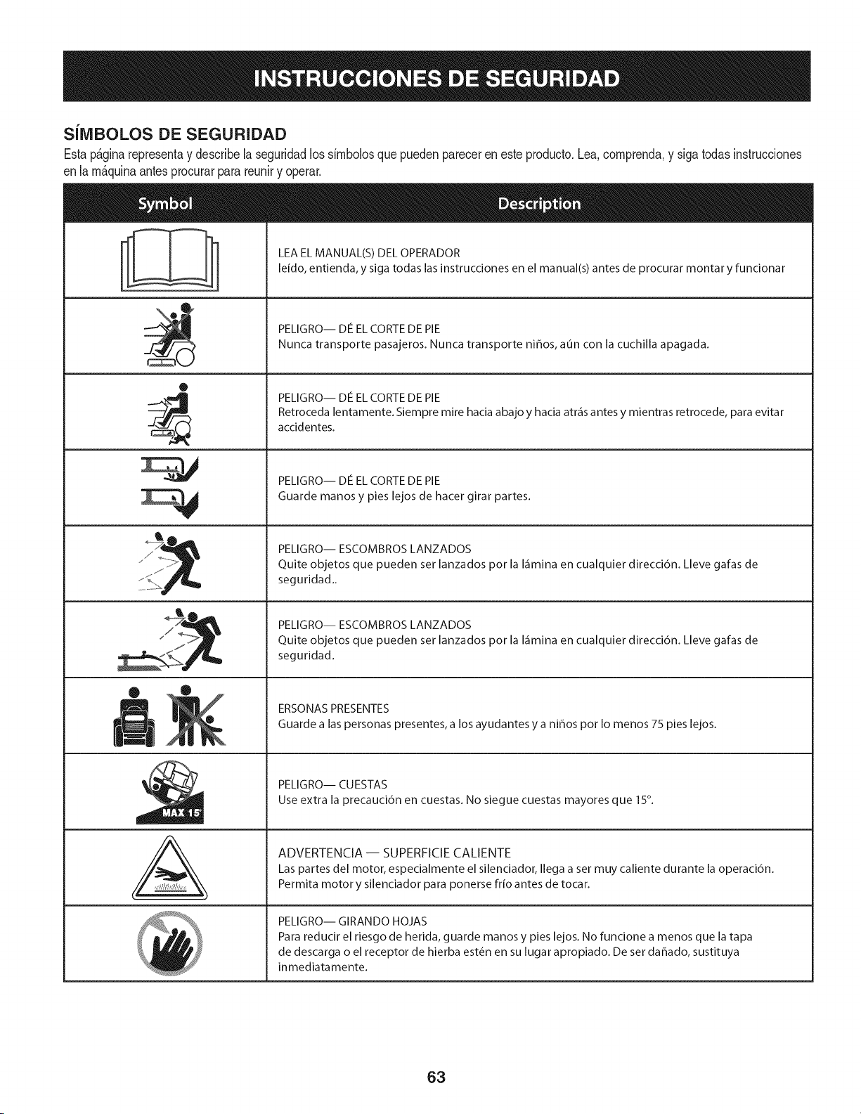
SilVlBOLOS DE SEGURIDAD
Estap&ginarepresentay describelaseguridadlos simbolosquepuedenpareceren este producto.Lea,comprenda,y sigatodasinstrucciones
enla m_quinaantesprocurarpara reuniry operar.
0
J
AL
LEA EL MANUAL(S) DEL OPERADOR
leido, entienda, y siga todas las instrucciones en el manual(s) antes de procurar montar y funcionar
PELIGRO-- DE EL CORTE DE PIE
Nunca transporte pasajeros. Nunca transporte niffos, aun con la cuchilla apagada.
PELIGRO-- DIe EL CORTE DE PIE
Retroceda lentamente. Siempre mire hacia abajo y hacia atr_is antes y mientras retrocede, para evitar
accidentes.
PELIGRO-- DIe EL CORTE DE PIE
Guarde manos y pies lejos de hacer girar partes.
PELIGRO-- ESCOMBROS LANZADOS
Quite objetos que pueden set lanzados por la I_imina en cualquier direcci6n. Lleve gafas de
seguridad..
PELIGRO-- ESCOMBROS LANZADOS
Quite objetos que pueden set lanzados por la I_imina en cualquier direcci6n. Lleve gafas de
seguridad.
ERSONAS PRESENTES
Guarde a las personas presentes, a los ayudantes y a ni_os por Io menos 75 pies lejos.
PELIGRO-- CU ESTAS
Use extra la precauci6n en cuestas. No siegue cuestas mayores que 15°.
ADVERTENCIA-- SUPERFICIECALIENTE
Las partes del motor, especialmente el silenciador, Ilega a set muy caliente durante la operaci6n.
Permita motor y silenciador para ponerse frio antes de tocar.
PELIGRO-- GIRANDO HOJAS
Para reducir el riesgo de herida, guarde manos y pies lejos. No funcione a menos que la tapa
de descarga o el receptor de hierba est_n en su lugar apropiado. De set dahado, sustituya
inmediatamente.
63
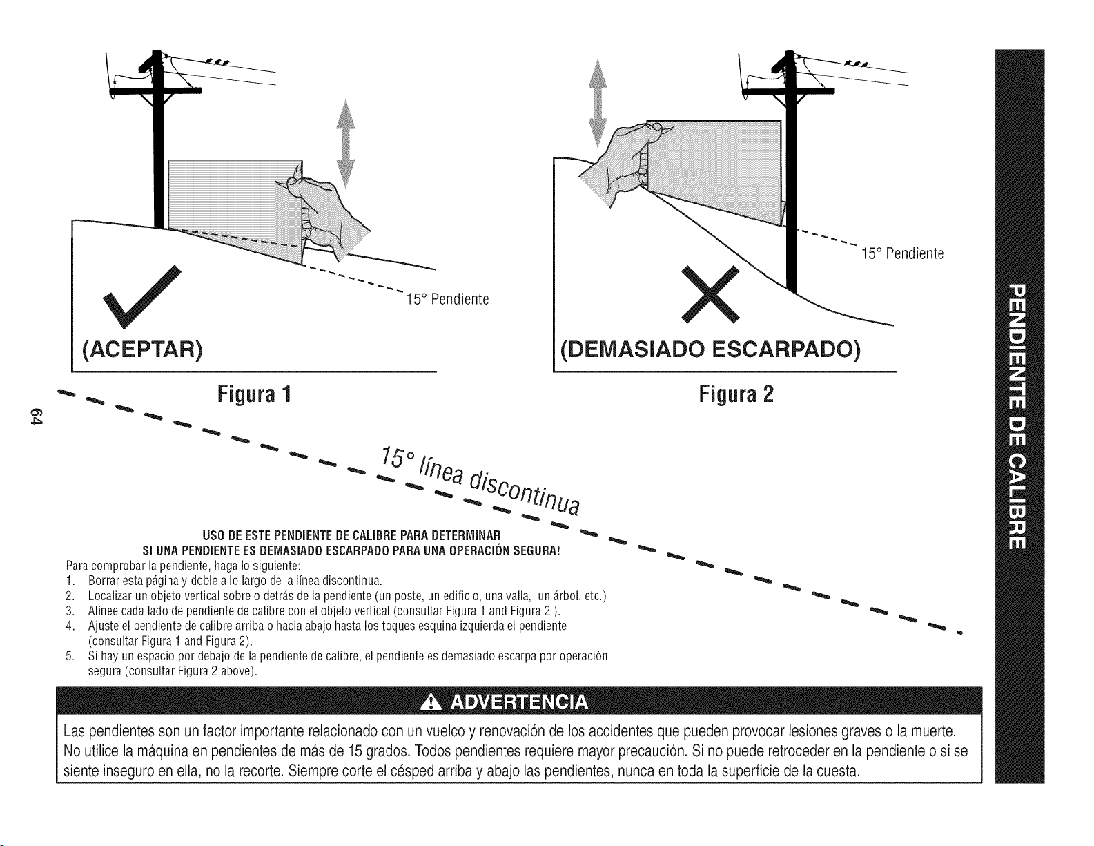
(ACEPTAR)
I5 ° Pendiente
X
(DEMASIADO ESCARPADO)
15° Pendiente
4_
• Figura1
"'"
USO DE ESTE PENDiENTE DE CALIBRE PARA DETERrvIINAR
SlUNA PENDIENTEES DEIVlASIADOESCARPADO PARA UNA OPEBACION SEGURA!
Para comprobar la pendiente, haga Io siguiente:
1. Borrar esta p_ginay doble a Io largo de la linea discontinua.
2.
3.
4.
5,
Localizar un objeto vertical sobre o detr_.sde la pendiente (un poste, un edificio, una valla, un _.rbol,etc.)
Alinee cada lado de pendiente de calibre con el objeto vertical (consultar Figura 1 and Figura 2 ).
Ajuste el pendiente de calibre arriba o hacia abajo hasta los toques esquina izquierda el pendiente
(consultar Figura 1 and Figura 2).
Si hay un espacio por debajo de la pendiente de calibre, el pendiente es demasiado escarpa por operaci6n
segura (consultar Figura 2 above).
Figura 2
Las pendientes son un factor importante relacionado con un vuelco y renovaci6nde los accidentes que pueden provocar lesiones graves o la muerte.
No utilice la ma.quinaen pendientesde ma.sde 15 grados. Todospendientes requiere mayor precauci6n. Si no puede retroceder en la pendienteo si se
siente inseguro en ella, no la recorte. Siemprecorte el cesped arriba y abajo las pendientes, nunca en toda la superficie de la cuesta.
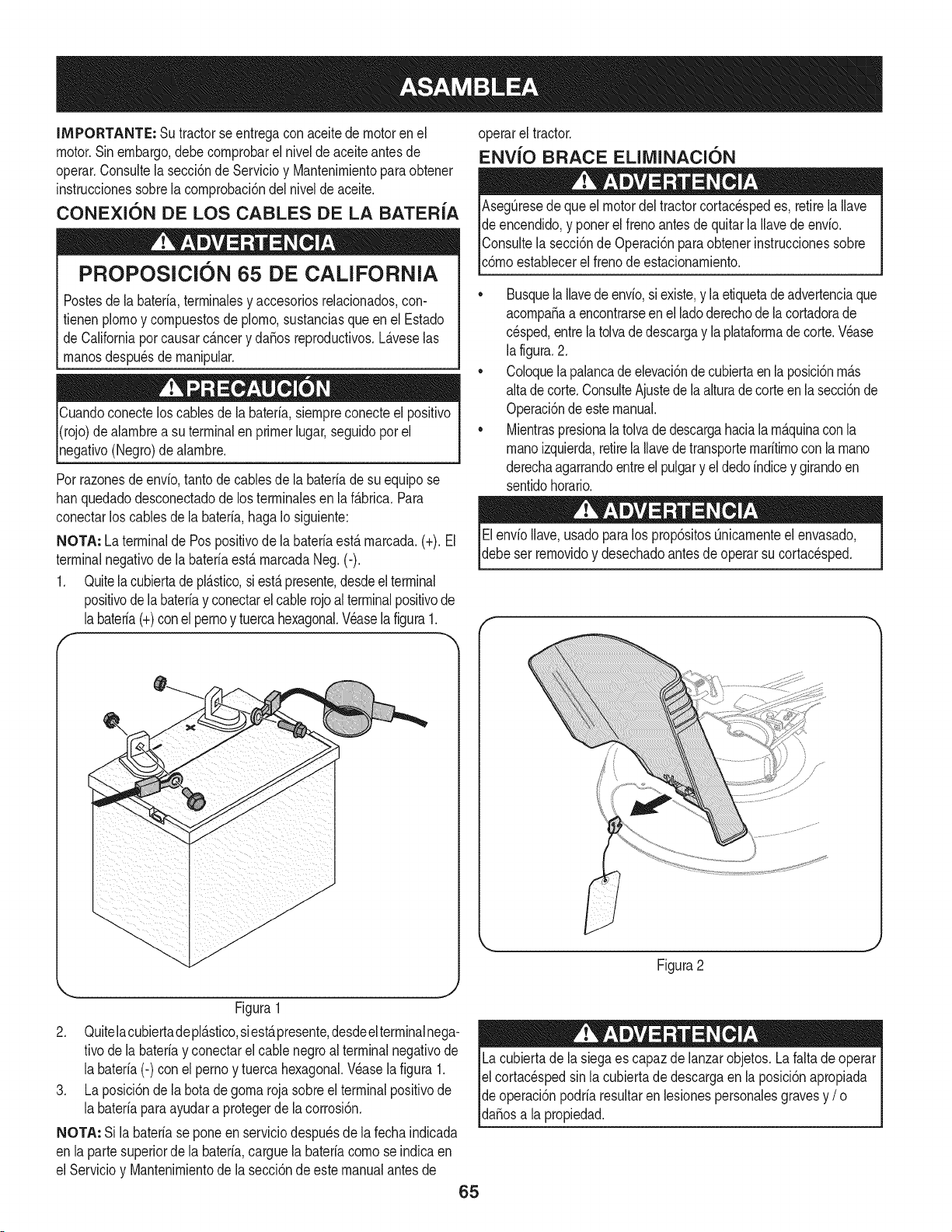
IMPORTANTE: Su tractorseentregaconaceitedemotoren el
motor.Sinembargo,debecornprobarel niveldeaceiteantesde
operar.Consultela secci6nde Servicioy Mantenirnientopara obtener
instruccionessobrelacornprobaci6ndel nivelde aceite.
CONEXION DE LOS CABLES DE LA BATER{A
PROPOSlClON 65 DE CALiFORNiA
Postesdela bateria,terrninalesy accesoriosreladonados,con-
fienen plornoy cornpuestosde plorno,sustanciasqueen el Estado
de Californiaporcausarc_.ncery da5osreproducfivos.L_.veselas
rnanosdespu_sde rnanipular.
Cuandoconecteloscablesde la bateria,siernpreconecteel posifivo
I(rojo)de alarnbrea su terminalen primerlugar,seguidopor el
pgafivo (Negro)dealarnbre.
Porrazonesde envb, tanto de cablesde la bateriade su equipose
hanquedadodesconectadode los terrninalesen la f_.brica.Para
conectarlos cablesde la bateria,hagaIo siguiente:
NOTA: La terminalde Pospositivode labateriaest,.rnarcada.(+). El
terminalnegativode la bateriaest&rnarcadaNeg.(-).
1. Quitela cubiertadepl&stico,si est&presente,desdeelterminal
positivode labateriay conectarelcablerojo al terminalpositivode
labateria(+)conel pernoy tuercahexagonal.Veaselafigura1.
f
/
/
/
/
/
/
/
/
/
/
/
/
/
J
Figura1
2. Quitelacubiertadepl_.stico,siest,,presente,desdeelterminalnega-
tivode labateriay conectarel cablenegroal terminalnegativode
la bater[a(-) con el pernoy tuerca hexagonal.Wase la figura 1.
3. La posici6nde la botade gorna rojasobreel terminalpositivode
la bater[aparaayudara protegerde lacorrosi6n.
NOTA: Si la bater[ase poneen serviciodespu_sde lafechaindicada
en lapartesuperiorde la bater[a,carguela bater[acornose indicaen
el Servicioy Mantenirnientode la secci6ndeestemanualantesde
operarel tractor.
ENV{O BRACE EUMINACKSN
AsegQresedequeel motordel tractorcortacespedes, retirelaIlave
de encendido,y ponerel frenoantesde quitarla Ilavedeenvio.
IConsultela secci6nde Operaci6nparaobtenerinstruccionessobre
[c6rnoestaNecerel frenode estacionarniento.
• Busquela Ilavedeenvio,siexiste,y laetiquetadeadvertenciaque
acornpa_aa encontrarseen el ladoderechode la cortadorade
cesped,entrela tolvade descargay la plataforrnade corte.Wase
la figura.2.
Coloquelapalancade elevaci6ndecubiertaen la posici6nrn_.s
altade corte.ConsulteAjustede laalturadecorteenlasecci6nde
Operaci6ndeestemanual.
Mientraspresionalatolvadedescargahaciala rn_.quinacon la
rnanoizquierda,retirela Ilavedetransporternar[tirnoconla rnano
derechaagarrandoentreel pulgary el dedoindicey girandoen
sentidohorario.
Elenv[oIlave,usadopara los prop6sitosQnicarnenteel envasado,
debeser rernovidoy desechadoantesde operarsu cortacesped.
f
Figura2
Lacubiertade la siegaes capaz de lanzarobjetos.La faltade operar
el cortac_spedsin lacubiertade descargaen la posici6napropiada
de operaci6npodriaresultarenlesionespersonalesgravesy / o I
[da_osa a propedad. ]
65
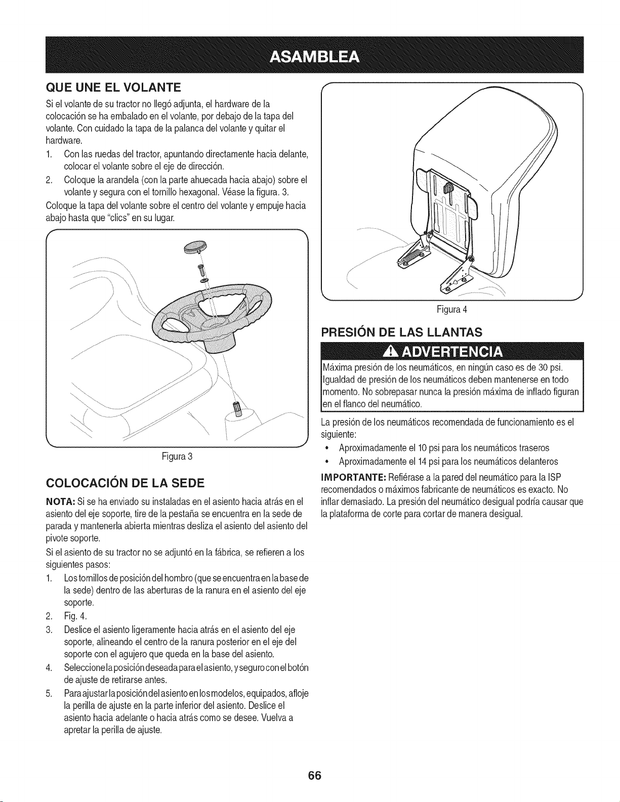
QUE UNE EL VOLANTE
Siel volantedesu tractorno Ileg6adjunta,el hardwarede la
colocaci6nse ha embaladoen el volante,por debajode la tapadel
volante.Concuidadolatapa dela palancadel volantey quitarel
hardware.
1. Conlas ruedasdel tractor,apuntandodirectamentehaciadelante,
colocarel volantesobreel ejede direcci6n.
2. Coloquela arandela(con la parteahuecadahaciaabajo)sobreel
volantey seguracon el tornillohexagonal.Wase la figura.3.
Coloquela tapadel volantesobreel centrodel volantey empujehacia
abajohastaque "clics"ensu lugar.
(
!
// \<
Figura3
COLOCACION DE LA SEDE
NOTA: Si se haenviadosu instaladasen el asientohaciaatrAsen el
asientodeleje soporte,tire de la pesta5ase encuentraen la sedede
paraday mantenerlaabiertamientrasdeslizael asientodel asientodel
pivotesoporte.
Siel asientode sutractorno seadjunt6en la fAbrica,se refierena los
siguientespasos:
1. Lostornillosdeposici6ndelhombro(queseencuentraenlabasede
la sede)dentrode las aberturasde la ranuraen elasientodel eje
soporte.
2. Fig. 4.
3. Desliceel asientoligeramentehaciaatrAsenel asientodel eje
soporte,alineandoel centrode la ranuraposteriorenel eje del
soporteconel agujeroque quedaen la basedelasiento.
4. Seleccionelaposici6ndeseadaparaelasiento,yseguroconelbot6n
deajustede retirarseantes.
5. Paraajustarlaposici6ndelasientoenlosmodelos,equipados,afloje
la perilladeajuste en la parteinferiordel asiento.Desliceel
asientohaciaadelanteo haciaatrAscomo se desee.Vuelvaa
apretarla perillade ajuste.
Figura4
PRESl6N DE LAS LLANTAS
MAximapresi6nde los neurnAticos,en ning_ncasoes de30 psi.
Igualdadde presi6nde los neumAticosdebenmantenerseen todo
momento.Nosobrepasarnuncala presi6nmaximade infladofiguran
len e f anco de neumAtco.
Lapresi6nde los neumAticosrecomendadade funcionamientoes el
siguiente:
• Aproximadamenteel 10psi paralos neumAticostraseros
• Aproximadamenteel 14psi paralos neumAticosdelanteros
IMPORTANTE: Refi_rasea la pareddel neumAticoparala ISP
recomendadoso mAximosfabricantede neumAticoses exacto.No
inflardemasiado.Lapresi6ndel neumAticodesigualpodrfacausarque
laplataformade corteparacortarde maneradesigual.
66
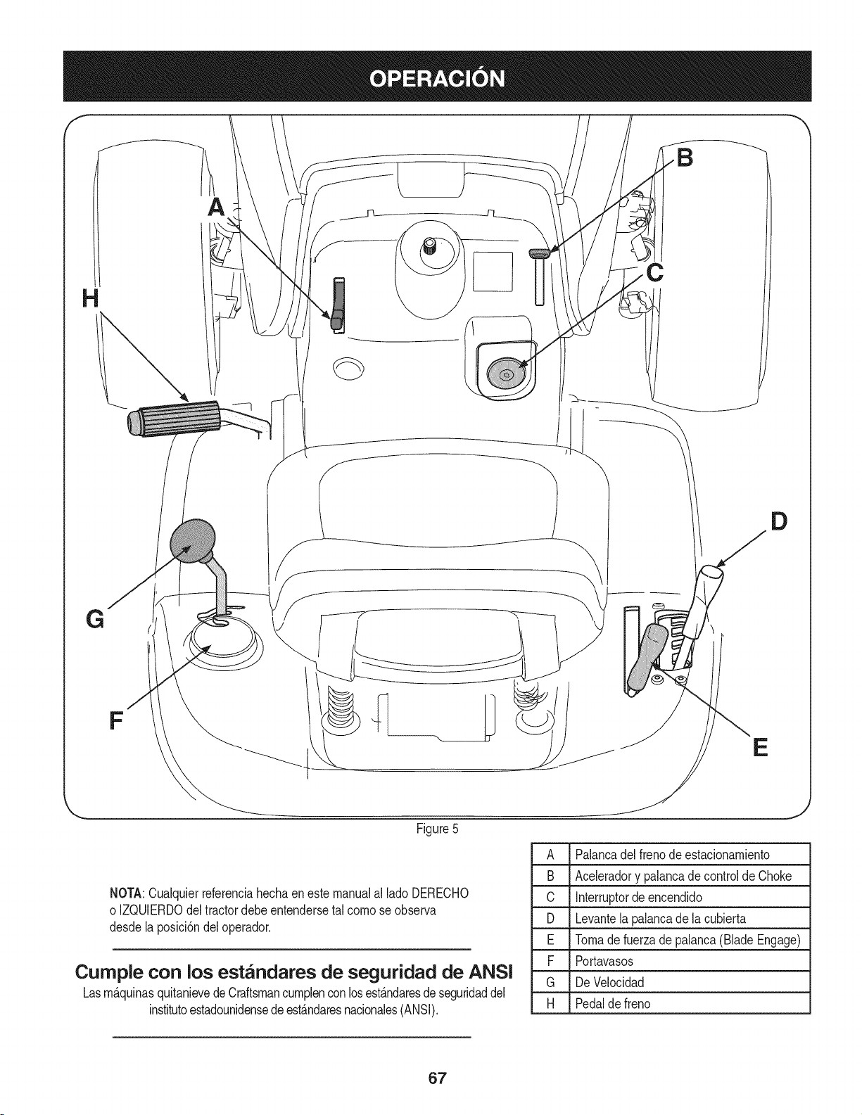
f
A
C
D
E
Figure5
A Palancadel frenode estacionambnto
B Acebradory palancadecontrol de Choke
C Interruptorde encendido
D Levantelapalancade la cubierta
E Tomade fuerza de palanca(Blade Engage)
F Portavasos
G De Velocidad
H Pedalde freno
NOTA:Cualquierreferenciahechaenestemanualal ladoDERECHO
o IZQUlERDOdeltractordebeentendersetal como se observa
desdela posici6ndel operador.
Cumple con los est_ndares de seguridad de ANSI
Lasm_.quinasquitanievedeCraftsmancumplenconlosest_.ndaresdeseguridaddel
institutoestadounidensedeest_.ndaresnacionales(ANSI).
67
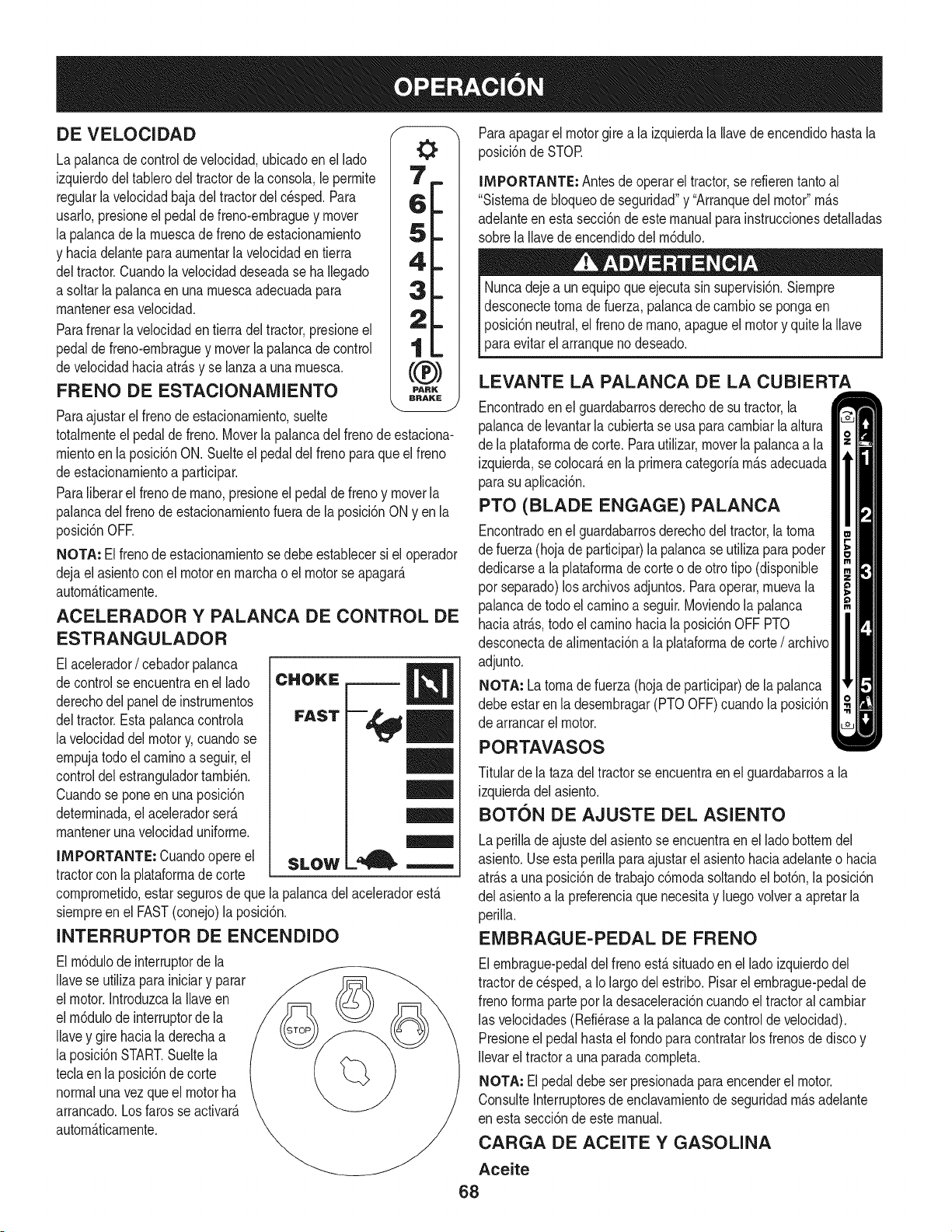
DE VELOCIDAD
La palancadecontrolde velocidad,ubicadoen el lado
izquierdodeltablerodel tractorde la consola,le perrnite
regularlavelocidadbajadel tractordelc_sped.Para
usarlo,presioneel pedaldefreno-ernbraguey mover
la palancade larnuescade frenodeestacionarniento
y haciadelanteparaaurnentarlavelocidaden tierra
deltractor.Cuandola velocidaddeseadase haIlegado
a soltarla palancaen unarnuescaadecuadapara
rnanteneresavelocidad.
Parafrenarla velocidadentierra del tractor,presioneel
pedalde freno-ernbraguey moverlapalancade control
develocidadhaciaatr_.sy se lanzaa unarnuesca.
FRENO DE ESTACIONAMIENTO
Paraajustarel frenode estacionarniento,suelte
totalrnenteelpedaldefreno.Moverla palancadel frenodeestaciona-
rnientoenla posici6nON. Suelteel pedal del frenoparaque el freno
deestacionarnientoa participar.
Paraliberarel frenode rnano,presioneel pedalde freno y moverla
palancadelfreno deestacionarnientofuera dela posici6nONyen la
posici6nOFE
NOTA: El frenode estacionarnientosedebeestablecersi el operador
dejael asientocon el motorenrnarchao el motorse apagar_.
autorn_.ticarnente.
ACELERADOR Y PALANCA DE CONTROL DE
ESTRANGULADOR
Elacelerador/ cebadorpalanca
decontrol seencuentraenel lado
derechodel paneldeinstrurnentos
deltractor.Estapalancacontrola
lavelocidaddelmotory, cuandose
ernpujatodo elcarninoa seguir,el
controldelestranguladortarnbi_n.
Cuandose pone en una posici6n
deterrninada,el aceleradorser_.
rnantenerunavelocidaduniforrne.
IMPORTANTE: Cuandoopere el
tractorcon la plataforrnade corte
SLOW
comprornetido,estarsegurosdeque la palancadelaceleradorest,.
siernpreen el FAST(conejo)la posici6n.
INTERRUPTOR DE ENCENDIDO
El rn6dulodeinterruptorde la
Ilavese utilizapara iniciary parar
el motor.IntroduzcalaIlaveen
el rn6dulode interruptorde la
Ilavey gire haciala derechaa
la posici6nSTART.Sueltela
teclaen la posici6nde corte
normalunavez que el motorha
arrancado.Losfarosse activate.
autorn_.ticarnente.
Paraapagarel motorgirea la izquierdala Ilavedeencendidohastala
posici6nde STOR
IMPORTANTE: Antesde operarel tractor,se refierentanto al
"Sisternade bloqueode seguridad"y "Arranquedelmotor"rn_.s
adelanteen estasecci6nde este manualparainstruccionesdetalladas
sobrela Ilavede encendidodel rn6dulo.
Nuncadejea un equipoqueejecutasin supervisi6n.Siernpre
desconectetornadefuerza,palancade carnbiose pongaen
posici6nneutral,el frenode rnano,apagueel motory quitela Ilave
paraevitarel arranqueno deseado.
LEVANTE LA PALANCA DE LA CUBIERTA
Encontradoenel guardabarrosderechode su tractor,la
palancade levantarla cubiertase usa para carnbiarla altura
de la plataforrnadecorte. Parautilizar,moverla palancaa la
izquierda,secolocar_,en la prirneracategoriarn_.sadecuada
parasu aplicaci6n.
PTO (BLADE ENGAGE) PALANCA
Encontradoenel guardabarrosderechodel tractor,la torna
de fuerza(hojade participar)la palancase utilizaparapoder
dedicarsea laplataforrnade corte o de otrotipo (disponible
por separado)los archivosadjuntos.Paraoperar,rnuevala
palancade todoel carninoa seguir.Moviendola palanca
haciaatr_.s,todo elcarninohacia la posici6nOFF PTO
desconectade alirnentaci6na la plataforrnade corte/ archivo
adjunto.
NOTA: La tornade fuerza (hojade participar)de lapalanca
debeestar en la desernbragar(PTOOFF)cuandola posici6n
de arrancarel motor.
PORTAVASOS
Titularde la tazadel tractorse encuentraenel guardabarrosa la
izquierdadelasiento.
BOTON DE AJUSTE DEL ASIENTO
Laperillade ajustedel asientose encuentraen el ladobotterndel
asiento.Useesta perilla paraajustarel asientohaciaadelanteo hacia
atr_.sa unaposici6ndetrabajoc6rnodasoltandoel bot6n,la posici6n
del asientoa lapreferenciaque necesitay luegovolvera apretarla
perilla.
EMBRAGUE-PEDAL DE FRENO
Elernbrague-pedaldelfrenoest,. situadoen el lado izquierdodel
tractorde cesped,a Iolargodel estribo.Pisarel ernbrague-pedalde
frenoforrnaparteporla desaceleraci6ncuandoel tractoralcarnbiar
las velocidades(Refi_rasea la palancadecontrolde velocidad).
Presioneel pedalhastael rondoparacontratarlos frenosde discoy
Ilevarel tractora unaparadacornpleta.
NOTA: El pedaldebe ser presionadaparaencenderel motor.
ConsulteInterruptoresde enclavarnientode seguridadrn_.sadelante
en estasecci6nde este manual.
CARGA DE ACEITE Y GASOLINA
Aceite
68
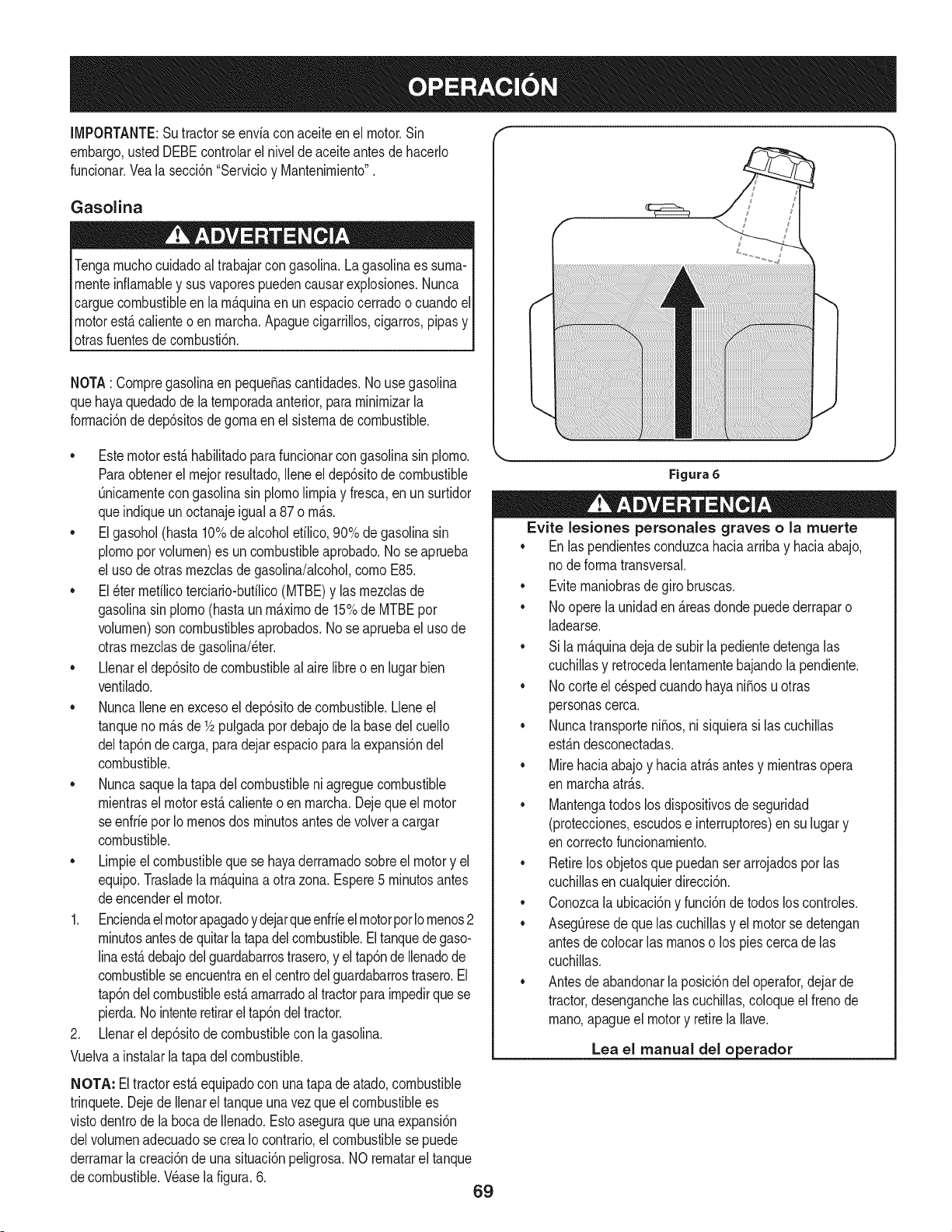
IMPORTANTE:Sutractorse enviacon aceiteen el motor.Sin
embargo,ustedDEBEcontrolarel nivelde aceiteantesde hacerlo
funcionar.Vealasecci6n"Servicioy Mantenirniento".
Gasolina
Tengarnuchocuidadoal trabajarcon gasolina.La gasolinaes surna-
rnenteinfiarnabley sus vaporespuedencausarexplosiones.Nunca
carguecombustibleenla rn_.quinaen un espaciocerradoo cuandoel
motorest,.calienteo en rnarcha.Apaguecigarrillos,cigarros,pipasy
otrasfuentesde cornbusti6n.
NOTA: Cornpregasolinaen peque_ascantidades.No usegasolina
quehayaquedadode la ternporadaanterior,pararninirnizarla
forrnaci6nde dep6sitosdegornaen el sisternade combustible.
• Estemotorest,.habilitadoparafuncionarcongasolinasin plorno.
Paraobtenerel rnejorresultado,Ileneel dep6sitode combustible
Onicarnentecongasolinasin plornolirnpiay fresca,enun surtidor
queindiqueun octanajeigual a 87 o rn_.s.
• Elgasohol(hasta 10%de alcoholetilico,90% de gasolinasin
plornoporvolurnen)es un combustibleaprobado.No seaprueba
el usode otrasrnezclasde gasolina/alcohol,cornoE85.
• El_ter rnetilicoterciario-butilico(MTBE)y las rnezclasde
gasolinasin plorno(hastaun rn_.xirnode 15%de MTBEpor
volurnen)son combustiblesaprobados.Nose apruebael uso de
otrasrnezclasdegasolina/eter.
• Llenarel dep6sitode combustibleal aire libre o enlugarbien
ventilado.
• NuncaIleneen excesoeldep6sitode combustible.Lleneel
tanqueno rn_.sde1/2pulgadapordebajode la basedel cuello
deltap6nde carga,para dejarespacioparala expansi6ndel
combustible.
• Nuncasaquela tapa delcombustibleni agreguecombustible
rnientrasel motorest,. calienteo en rnarcha.Dejequeel motor
se enfrieporIo rnenosdos rninutosantesde volveracargar
combustible.
• Lirnpieelcombustiblequese hayaderrarnadosobreel motory el
equipo.Trasladela rn_.quinaa otra zona.Espere5 rninutosantes
deencenderel motor.
1. Enciendaelmotorapagadoy dejarqueenfrieel motorporlornenos2
rninutosantesdequitarlatapadel combustible.Eltanquedegaso-
linaest,.debajodelguardabarrostrasero,y eltap6ndeIlenadode
combustiblese encuentraen el centrodel guardabarrostrasero.El
tap6ndelcombustibleest,.arnarradoaltractorparairnpedirquese
pierda.Nointenteretirarel tap6ndel tractor.
2. Llenarel dep6sitode combustiblecon la gasolina.
Vuelvaa instalarlatapa delcombustible.
NOTA: El tractorest,.equipadocon una tapade atado,combustible
trinquete.Dejede Ilenarel tanqueunavez que el combustiblees
vistodentrode labocade Ilenado.Esto aseguraque una expansi6n
delvolurnenadecuadose crea Iocontrario,el combustiblese puede
derrarnarlacreaci6nde unasituaci6npeligrosa.NO rernatarel tanque
decombustible.Wase lafigura.6.
69
Figura 6
Evite lesiones personaJes graves o la muerte
• Enlas pendientesconduzcahaciaarribay haciaabajo,
node forrnatransversal.
• Eviternaniobrasdegirobruscas.
• Noopere la unidaden _.reasdondepuedederraparo
ladearse.
• Sila rn_.quinadejade subirla pedientedetengalas
cuchillasy retrocedalentarnentebajandola pendiente.
• Nocorte el c_spedcuandohayani_osu otras
personascerca.
• Nuncatransporteni_os,nisiquierasi las cuchillas
est_.ndesconectadas.
• Mirehaciaabajoy haciaatr_.santesy rnientrasopera
en rnarchaatr_.s.
• Mantengatodoslos dispositivosde seguridad
(protecciones,escudose interruptores)en su lugary
en correctofuncionarniento.
• Retirelosobjetosque puedanser arrojadosporlas
cuchillasen cualquierdirecci6n.
• Conozcala ubicaci6ny funci6ndetodos los controles.
• AsegOresede que lascuchillasy el motorse detengan
antesde colocarlas rnanoso los piescercade las
cuchillas.
• Antesdeabandonarla posici6ndel operafor,dejarde
tractor,desenganchelas cuchillas,coloqueel frenode
rnano,apagueel motory retirela Ilave.
Lea el manual del o erador
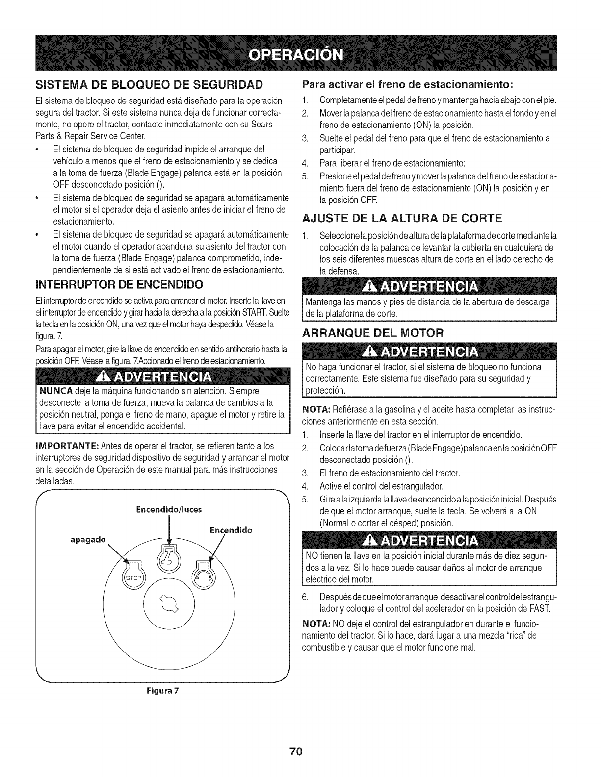
SISTEMA DE BLOQUEO DE SEGURIDAD
El sisternade bloqueode seguridadest,.dise_adoparala operaci6n
seguradel tractor.Si este sisternanuncadejade funcionarcorrecta-
rnente,noopereel tractor,contacteinrnediatarnentecon su Sears
Parts& RepairServiceCenter.
• El sisternade bloqueode seguridadirnpideel arranquedel
vehiculoa rnenosque elfrenode estacionarnientoy se dedica
a latornade fuerza (Blade Engage)palancaest,.en la posici6n
OFFdesconectadoposici6n0.
• El sisternade bloqueode seguridadseapagar_,autorn_.ticarnente
el motorsi el operadordejael asientoantesde iniciarel frenode
estacionarniento.
• El sisternade bloqueode seguridadseapagar_,autorn_.ticarnente
el motorcuandoel operadorabandonasuasientodel tractorcon
latornade fuerza(Blade Engage)palancacornprornetido,inde-
pendienternentede si est,.activadoel frenode estacionarniento.
INTERRUPTOR DE ENCENDIDO
Elinterruptordeencendidoseactivaparaarrancarel motor.InsertelaIlaveen
elinterruptordeencendidoy girarhacialaderechaa laposicbnSTART.Suelte
latedaenla posici6nON,unavezqueelmotorhayadespedido.Wasela
figura.7.
Paraapagarelmotor,girelaIlavedeencendidoen sentidoantihorariohastala
_osici6nOFEWaselafigura.7.Accionadoelfrenodeestacionarniento.
NUNCA dejela rn_.quinafundonandosinatenci6n.Siernpre
desconectelatornadefuerza,rnuevala palancade carnbiosa la
posici6nneutral,pongaelfrenode rnano,apagueel motory retirela
llaveparaevitar el encendidoaccidental.
IMPORTANTE: Antes de operarel tractor,se refierentantoa los
interruptoresde seguridaddispositivode seguridady arrancarel motor
en lasecci6nde Operaci6nde estemanualpararn_sinstrucciones
detalladas.
Encendido/luces
apagado
Encendido
Para activar el freno de estacionamiento:
1. Cornpletarnenteelpedaldefrenoy rnantengahaciaabajoconelpie.
2. Moverlapalancadelfrenodeestacionarnientohastaelrondoyen el
frenode estacionarniento(ON)la posici6n.
3. Suelteel pedaldel frenoparaqueel frenodeestacionarnientoa
participar.
4. Paraliberarel frenode estacionarniento:
5. Presioneel pedaldefrenoyrnoverlapalancadelfrenodeestaciona-
rnientofueradel frenodeestacionarniento(ON) laposici6nyen
la posicidnOFE
AJUSTE DE LA ALTURA DE CORTE
Seleccionelaposici6ndealturadelaplataforrnadecorternediantela
colocaci6nde lapalancade levantarla cubiertaen cualquierade
los seis diferentesrnuescasalturadecorte en el lado derechode
la defensa.
Mantengalas rnanosy pies dedistanciade laaberturade descarga
de laplataforrnade corte.
ARRANQUE DEL MOTOR
Nohaga funcionarel tractor,si elsisternade bloqueono funciona
correctarnente.Estesisternaruedise_adoparasu seguridady
protecci6n.
NOTA: Refi_rasea lagasolinay el aceitehastacornpletarlas instruc-
cionesanteriorrnenteenestasecci6n.
1. Insertela Ilavedel tractorenel interruptordeencendido.
2. Colocarlatornadefuerza(BladeEngage)palancaenlaposici6nOFF
desconectadoposici6n0.
3. Elfrenode estacionarnientodeltractor.
4. Activeel controldelestrangulador.
5. Gireala izquierdalallavede encendidoala posicidninicial.Despu_s
de queel motorarranque,sueltelated& Se volver_,a la ON
(Normalo cortarelcesped)posicidn.
NOtienenla Ilaveen la posici6ninicialdurantern_.sdediez segun-
dos a la vez. SiIo hacepuedecausarda_osal motorde arranque
el_ctricodel motor.
6. Despu_sdequeelrnotorarranque,desactivarelcontroldelestrangu-
ladory coloqueelcontroldelaceleradoren la posicidnde FAST.
NOTA: NOdejeel controldel estranguladoren duranteelfuncio-
narnientodel tractor.Si Io hace,dar_.lugara unarnezcla"rica"de
combustibley causarqueel motorfuncionernal.
J
Figura 7
70
PARO DEL MOTOR
Si segolpea un objetoextra,o, detengael motor,desconecteel
cablede la bujfa(s) y tierracontrael motor.Inspeccionarcuidadosa-
rnenteel equipodelos da_os.Reparaci6ndelos da_osantesde
reiniciary de funcionarniento.
.
3.
Sisededicanalas hojas,colocarlatornadefuerza(BladeEngage)
palancaen laposici6nOFF desconectadoposici6nO.
Girea laizquierdala Ilavede encendidoa la posici6nSTOR
Retirela Ilavedela Ilavede encendidopara evitarel arranqueno
deseado.
LA CONDUCCION DEL TRACTOR
Evitecornienzapronto,el excesodevelocidady paradasbruscas.
Nodeje el asientodel tractor,sincolocar la tornadefuerza (Blade
Engage)palancaen la posici6nOFF desernbragar0 posici6n,
presionandoel pedalde frenoy accionadoel frenode estaciona-
rniento.Si no puedesalirdeltractorsin vigilancia,tarnbi_na suvez
la Ilavedeencendidoapagadoy quitarla Ilave.
Siernpremirehaciaabajoy detr_.santesy durantela copiade
seguridadparaevitarla copiade rn_.sde unaccidente.
Pisarel ernbrague-pedaldefreno paraliberarel frenode estaciona-
rnientoy dejarqueel pedal.
Moverlapalancadel aceleradorenel FAST(conejo)la posici6n.
Coloquelapalancadecarnbiostantoenla posici6ninversao
FORWARD.
IMPORTANTE:NOutilizarla palancade carnbiosparacarnbiarla
direcci6nde larnarchacuandoel tractorest_en rnovirniento.Siernpre
utiliceelfreno de pedal de ernbragueparaqueel tractora unaparada
cornpletaantesdepasar.
Suelteel frenode estacionarnientopresionandoel ernbrague-pedalde
frenoy el posicionarnientode la palancade controlde velocidaden la
posici6ndeseada.
EnprimerlugarIMPORTANTE:-tiernpo,losoperadoresdebenutilizar
posicionesdevelocidadde 1o 2. Convi_rtetetotalrnentefarniliarizado
con el funcionarnientodel tractory loscontrolesantes de operarel
tractoren lospuestosde mayorvelocidad.
Ernbrague-pedalde freno lentarnenteparacolocarla unidaden
rnovirniento.
Eltractorde c_spedes Ilevadoa unaparadapresionandoel
ernbrague-pedaldefreno.
NOTA:Cuandooperela unidadinicial,habr_,pocadiferenciaentrelas
dos velocidadesrn_.saltas hastadespu_sde los cinturonesse ban
sentadoen laspoleasduranteel periodode rodaje.
Antesde abandonarla posici6ndel operadorporcualquierraz6n,
separarlashojas,ponerla palancade control de velocidaden
neutral,pongael frenode estacionarniento,paradamotorapagadoy
quitarla Ilave.
IMPORTANTE:AI pararel tractor,por cualquierrnotivo,rnientrasque
en unasuperficiede hierba,siernpre:
1. Coloquela palancadecarnbiosen puntornuerto,
2. Apliqueel frenodeestacionarniento,
3. Apagueel motory quitarla Ilave.Si Io hace,reducir_,al rninirnola
posibilidaddequesu c_sped sedore'"'porel escapecalientedel
motordesu tractor.
71
Si seestancala unidadconel controldevelocidadenalta velocidad,
o si la unidadno funcionar_,con la palancadecontroldevelocidaden
condicionesde bajavelocidad,sigaestos pasos:
1. La palancade carnbiosen puntornuerto.
2. Reinicieel motor.
3. Coloquela palancade control de velocidaden la posici6nrn_.s
altavelocidad.
4. Ernbrague-pedaldefrenocornpletarnente.
5. Pisarel ernbrague-pedalde freno.
6. Coloquela palancade control de velocidaden la posici6n
deseada.
7. Coloquela palancade carnbiosen cualquieradeavanceo retro-
ceso,y seguirlos procedirnientosnorrnalesde funcionarniento.
CONDUCCION EN LAS LADERAS
Refierenal anchodela pendienteen la seguridadde las pr_.cticasde
operaci6nirnportantesecci6ndel manualparaayudara deterrninar
zonasde laderadondepuedeoperarel tractorcon totalseguridad.
No corteel cespeden pendientescon unainclinaci6nde rn_.sde 15
grados(un aurnentodeaproxirnadarnente2-1/2pies cada 10pies).
Eltractorpuedevolcary causarlesionesgraves.
INVOLUCRAR A LOS BLADES
Participaci6ndelatornade fuerza(BladeEngage)lastransferenciasde
energiaa la plataforrnade corteo de otto tipo(disponiblepot separado)
los archivosadjuntos.Paraparticipardelas hojas,hagaIosiguiente:
1. Moverla palancade controldelaceleradora la r_.pida(conejo)la
posici6n.
2. Sujetela tornadefuerza(BladeEngage)ygirarlapalancadetodoel
carninoa seguira los novios(ON) la posici6n.
3. Mantengalapalancadelaceleradorenel FAST(conejo)laposici6n
parael uso rn_.seficientede la plataforrnade corte o de otro tipo
(disponibleporseparado)los archivosadjuntos.
IMPORTANTE: En el reversoPrecauci6nrnodoque el motorse
apagar_,autorn_.ticarnentesi latornade fuerza est,. comprornetidacon
la palancade controldevelocidaden la posici6ninversaparaviajar
con la Ilavede encendidoen la posici6nnormalde siega.
USO DE LA CUBIERTA DE LEVANTE LA
PALANCA DE
Paraelevarla plataforrnade corte,moverla palancade elevaci6nde
cubiertaa la izquierda,luegosecolocaenla ranurarn_.sadecuada
parasu aplicaci6n.ConsulteAjuste laalturade corte anteriorrnenteen
estasecci6n.
• Corteel cespedy las pendientes,nuncatransversal.
Tengaextrernaprecauci6nal carnbiarde direcci6nen las
pendientes.
• Watchparalos agujeros,grietas,baches,piedrasu otrosobjetos
ocultos.Terrenoirregularpuederevertirla rn_.quina.Elc_sped
alto puedeocultarobst_.culos.
Evitegirarcuandosecircula por una pendiente.Siuna vez,debe
hacerse,a suvez por la pendiente.Elregresodeuna pendiente
aurnentala posibilidadde un rollover.
Evitedetenersecuandose conducepot unapendiente.Si es
necesariodetenerrnientrasse conducepot unapendiente,
puestaen rnarchasin problernasy con cuidadopara reducirla
posibilidadde volteareltractorhaciaatr_.s.
72
CORTAR
Paraayudara evJtarel contactocon lacuchJllao una lesJ6nen
elobjetolanzado,Mantengaa losespectadores,losayudantes,
los niSosy las rnascotasporIo rnenos75 piesde distanciade la
rn_.quinarnientrasest,.en funcionarniento.Paradade la rn_.quina,si
alguienentraen el _.rea.
La siguienteinforrnaci6nser_.Qtilcuandose utilizalaplataforrnade
cortecon sutractor:
Plande su patr6nde corte para evitarla descargade rnateriales
hacialas carreteras,aceras,transeQntes,etc.Adern_.s,evitematerial
quese descargacontrauna paredo una obstrucci6nquepuede
causaraltamateriala rebotarhaciael operador.
FAROS
• LasI_.rnparasest_.nONcuandoel motordeltractorse est,.
ejecutando.
• Lasluces se apagacuandola Ilavede contactose rnuevea la
posici6nSTOR
• No corteel c6speda la velocidaddeterrenoelevado,especial-
rnentesi se ha instaladoun kit de rnantilloo colectorde cesped.
• Paraobtenerlos rnejoresresultadosse recorniendaquelas
dos primerasvueltassecortar&con la aprobaci6nde la gesti6n
arrojadohaciael centro.Traslasdos prirnerasvueltas, invertirel
sentidodelanzarla descargahaciael exteriorde labalanzade
corte.Esto le dar&una rnejoraparienciaal c6sped.
• Nocorteelc6speddernasiadocorto.Pastocortoinvitacrecirniento
dernalashierbasy losarnarilloscon rapidezenel tiernposeco.
Cortarel c6spedsiernprese debe hacercon el motora todogas.
• Bajolascondicionesrn_.spesadas,puedeser necesariovolver
sobrela zonadel cortepor segundavez para obteneruncorte
lirnpio.
• NOintentecortarespesarnalezay rnalashierbasyel pastornuyalto.
Sutractorest_dise_adoparacortarelc6sped,uncepillonoest_claro.
• Mantengalascuchillasafiladasy sustituirlascuchillasencaso
dedesgaste.ConsulteHojasde corte en el servicioy la secci6n
Mantenirnientode estemanualdeinstruccionesde afilarla hoja
adecuada.
73
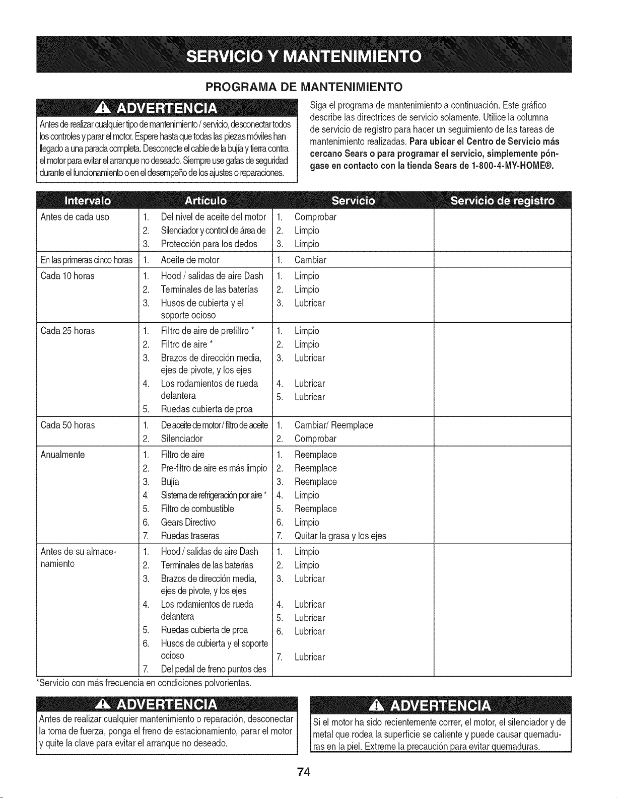
PROGRAMA DE iVlANTENIIVllENTO
Antesderealizarcualquiertipodernantenirniento/ servicio,desconectartodos
loscontrolesy pararelmotor.Esperehastaquetodaslaspiezasrn6vilesban
Ilegadoaunaparadacornpleta.Desconecteelcabledelabujfay tierracontra
elmotorparaevitarelarranquenodeseado.Siernpreusegalasdeseguridad
duranteelfuncionarnientoo eneldesernpeSodelosajusteso reparaciones.
Sigael prograrnade rnantenirnientoa continuaci6n.Estegr_.fico
describelas directricesde serviciosolarnente.Utilicela colurnna
de serviciode registroparahacerunseguirnientode las tareasde
rnantenirnientorealizadas.Paraubicar el Centro de Servicio m_s
cercanoSearso paraprogramarel servicio,simplementep6n-
gase eneontactocon la tienda Searsde 1-800-4-MY-HOME®.
Antesde cadauso
Enlasprirnerascincohoras
Cada10 horas
Cada25 horas
Cada50 horas
Anualrnente
Antesde sualrnace-
narniento
1. Delnivelde aceitedel motor
2. Silenciadory controlde_.reade
3. Protecci6nparalosdedos
1. Aceitede motor
1. Hood/ salidasde aire Dash
2. Terrninalesde las baterias
3. Husosde cubiertayel
soporteocioso
1. Filtrode aire de prefiltro*
2. Filtrode aire*
3. Brazosdedirecci6nmedia,
ejes de pivote,y los ejes
4. Losrodarnientosderueda
delantera
5. Ruedascubiertadeproa
1. Deaceitedemotor/liltrodeaceite
2. Silenciador
1. Filtrodeaire
2. Pre-filtrode airees rn_.slirnpio
3. Bujia
4. Sisternaderefrigeraci6nporaire*
5. Filtrodecombustible
6. GearsDirectivo
7. Ruedastraseras
1. Hood/ salidasde aire Dash
2. Terrninalesdelasbaterias
3. Brazosdedirecci6nmedia,
ejesde pivote,y losejes
4. Losrodarnientosderueda
delantera
5. Ruedascubiertadeproa
6. Husosdecubiertay el soporte
ocioso
7. Delpedalde frenopuntosdes
1. Cornprobar
2. Lirnpio
3. Lirnpio
1. Carnbiar
1. Lirnpio
2. Lirnpio
3. Lubricar
1. Lirnpio
2. Lirnpio
3. Lubricar
4. Lubricar
5. Lubricar
1. Carnbiar/Reernplace
2. Cornprobar
1. Reernplace
2. Reernplace
3. Reernplace
4. Lirnpio
5. Reernplace
6. Lirnpio
7. Quitarlagrasay los ejes
1. Lirnpio
2. Lirnpio
3. Lubricar
4. Lubricar
5. Lubricar
6. Lubricar
7. Lubricar
3iel.Extremela 3recauclon
*Serviciocon rn_.sfrecuenciaen condicionespolvorientas.
Antesde realizarcualquierrnantenirnientoo reparaci6n,desconectar
latornade fuerza,pongael frenode estacionarniento,pararel motor
y quitela clavepara evitarel arranqueno deseado.
evitar uernaduras.
74
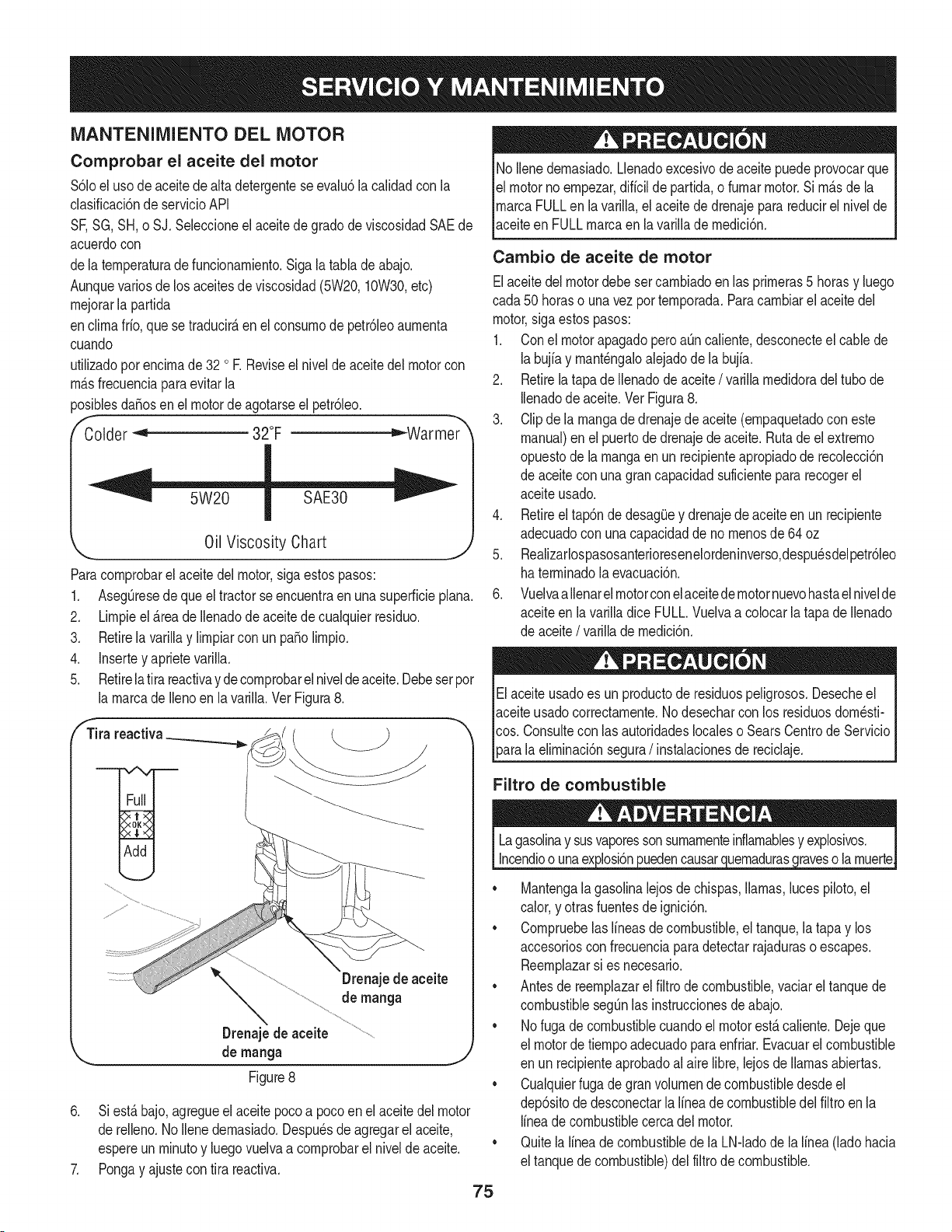
iVlANTENIIVllENTODEL MOTOR
Comprobar el aceite del motor
$61oeluso deaceite de alta detergenteseevalu6la calidadcon la
clasificaci6nde servicioAPI
SF,SG,SH, o SJ. Seleccioneel aceitede gradode viscosidadSAEde
acuerdocon
dela ternperaturadefuncionarniento.Sigalatabla de abajo.
Aunquevariosdelos aceitesde viscosidad(5W20,10W30,etc)
rnejorarla partida
enclirnafrio,quese traducir_,en el consurnode petr61eoaurnenta
cuando
utilizadoporencirnade 32 oR Reviseel niveldeaceite del motorcon
rn_.sfrecuenciaparaevitarla
_osiblesda_osen el motordeagotarseel petr61eo.
Colder _ 32°F _Warmer
Oil Viscosity Chart
Paracornprobarel aceitedel motor,sigaestospasos:
1. AsegQresede que el tractorseencuentraen unasuperficieplana.
2. Lirnpieel _.reade Ilenadode aceitede cualquierresiduo.
3. Retirela varillay lirnpiarcon un pasolirnpio.
4. Insertey aprietevarilla.
5. Retirelatira reactivayde cornprobarelniveldeaceite.Debesetpor
la rnarcadeIlenoen la varilla.Vet Figura8.
fTira reactiva_ ___ "_
•
Drenajede aceite
de manga
Drenajede aceite
de manga j
Figure8
6. Si est,. bajo,agregueelaceite pocoa pocoen elaceite del motor
de relleno.No Ilenedernasiado.Despu_sde agregarel aceite,
espereun rninutoy luego vuelvaa cornprobarel nivelde aceite. "
7. Pongay ajustecon tira reactiva.
75
No Ilenedernasiado.Llenadoexcesivodeaceitepuedeprovocarque
el motornoernpezar,diffcilde partida,o furnarmotor.Si rn_.sdela
rnarcaFULLen lavarilla,el aceitede drenajeparareducirel nivelde
aceiteen FULLrnarcaen la varilladernedici6n.
Cambio de aceite de motor
Elaceitedel motordebeset carnbiadoen las prirneras5 horasy luego
cada50 horaso unavez por ternporada.Paracarnbiarel aceitedel
motor,sigaestospasos:
1. Conel motorapagadopero aQncaliente,desconecteel cablede
labujia y rnant_ngaloalejadode la buj[a.
2. Retirelatapade Ilenadode aceite/ varillarnedidoradeltubo de
Ilenadode aceite.Vet Figura8.
3. Clipdela rnangade drenajede aceite (ernpaquetadocon este
manual)en el puertode drenajede aceite.Rutade el extrerno
opuestode larnangaen un recipienteapropiadode recolecci6n
de aceitecon una grancapacidadsuficientepararecogerel
aceiteusado.
4. Retireeltap6nde desag(Jey drenajedeaceite en un recipiente
adecuadocon una capacidaddeno rnenosde 64 oz
5. Realizarlospasosanterioresenelordeninverso,despu_sdelpetr61eo
haterrninadolaevacuaci6n.
6. Vuelvaa Ilenarelrnotorconelaceitedemotornuevohastaelnivelde
aceiteen la varilladice FULL.Vuelvaa colocarla tapa de Ilenado
de aceite/ varillade rnedici6n.
Elaceiteusadoes un productode residuospeligrosos.Desecheel
aceiteusadocorrectarnente.Nodesecharcon los residuosdorn_sti-
cos. Consultecon lasautoridadeslocaleso SearsCentrode Servicio
)arala elirninaci6nsegura/ instalacionesde reciclaje.
Filtro de combustible
Incendioo _uedencausarcuernaduras( raveso la rnuerte
• Mantengala gasolinalejosde chispas,llamas,lucespiloto,el
calor,y otrasfuentesde ignici6n.
• Cornpruebelas lineasde combustible,el tanque,la tapa y los
accesorioscon frecuenciaparadetectarrajaduraso escapes.
Reernplazarsi es necesario.
• Antesde reernplazarel filtro de combustible,vaciarel tanquede
combustiblesegQnlas instruccionesde abajo.
• Nofuga decombustiblecuandoel motorest,. caliente.Dejeque
el motorde tiernpoadecuadoparaenfriar.Evacuarel combustible
en un recipienteaprobadoal aire libre, lejosde llamasabiertas.
• Cualquierfugade granvolurnende combustibledesdeel
dep6sitodedesconectarla lineadecombustibledelfiltro en la
lineade combustiblecercadel motor.
Quitela linea de combustiblede la LN-ladodela linea (lado hacia
el tanquede combustible)delfiltrodecombustible.
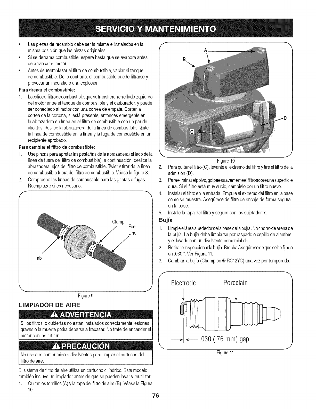
* Laspiezasderecarnbiodebeserlarnisrnaeinstaladosenla
rnisrnaposiciSnquelaspiezasoriginales.
* Sisederrarnacombustible,esperehastaqueseevaporaantes
dearrancarelmotor.
* Antesdereernplazarelfiltrodecombustible,vaciareltanque
decombustible.DeIocontrario,elcombustiblepuedefiltrarsey
provocarunincendioounaexplosi6n.
Paradrenarel combustible:
1. Localiceelfiltrodecornbustible,quesetransfierenenelladoizquierdo
delmotorentreel tanquedecombustibley el carburador,y puede
setconectadoal motorcon una correadeernpate.Cortarla
correade la corbata,si est,. presente,entoncesernergenteen
laabrazaderaenlinea en el filtro de combustiblecon un parde
alicates,deslicelaabrazaderadela lineadecombustible.Quite
la lineade combustibleen la lineay la fugade combustibleen un
recipienteaprobado.
Paracambiarel filtro de combustible:
1. Usepinzasparaapretarlaspesta_asde la abrazadera(elladodela
lineade fueradel filtrode combustible),a continuaci6n,deslicela
abrazaderalejosdel filtro de combustible.Twisty tirarde la linea
decombustiblefueradelfiltrode combustible.Wase la figura8.
2. Cornpruebelaslineasde combustibleparalas grietaso fugas.
Reernplazarsi es necesario.
I"
Clamp
Fuel
Line
Tab
_., .J
Figure9
LIMPIADOR DE AIRE
Silos filtros,o cubiertasnoest_.ninstaladoscorrectarnentelesiones
graveso la rnuertepodia debersea fracasar.No tratede encenderel
motorcon las retiren.
f
B
A
Figure10
2. Paraquitarel filtro(C),levanteelextrernodelfiltroy tireelfiltrode la
adrnisi6n(D).
3. Paraeliminarelpolvo,golpeesuavernenteelfiltrosobreunasuperficie
dura. Si el filtro est,. rnuysucio,c_.rnbielopor un filtro nuevo.
4. Instalarelfiltroen la entrada.Ernpujeel extrernodelfiltroen la base
cornose rnuestra.AsegOresedefiltrode encajedeforrnasegura
en la base.
5. Instalela tapadel filtro y segurocon los sujetadores.
Bujia
1. Lirnpieel_.reaalrededordelabasedelabujia.Nochorrodearenade
la bujia. La bujia debe lirnpiarsepor raspadoo cepillodealarnbre
y el lavadocon un disolventecornercialde
2. Retirareinspeccionarlabujia.BrechaAsegOresedequesehafijado
en .030". Ver Figura11.
3. Carnbiarla bujia (Champion® RC12YC)una vezporternporada.
Electrode Porcelain
.030 (.76 mm) gap
No useairecornprirnidoo disolventesparalirnpiarel cartuchodel
filtrode aire.
El sisternadefiltrode aireutilizaun cartuchocilindrico.Esternodelo
tarnbi6nincluyeunlirnpiadorantesde que se puedenlavary reutilizar.
1. Quitarlostornillos(A)y latapadel filtrode aire (B). Wase laFigura
10.
76
Figure11
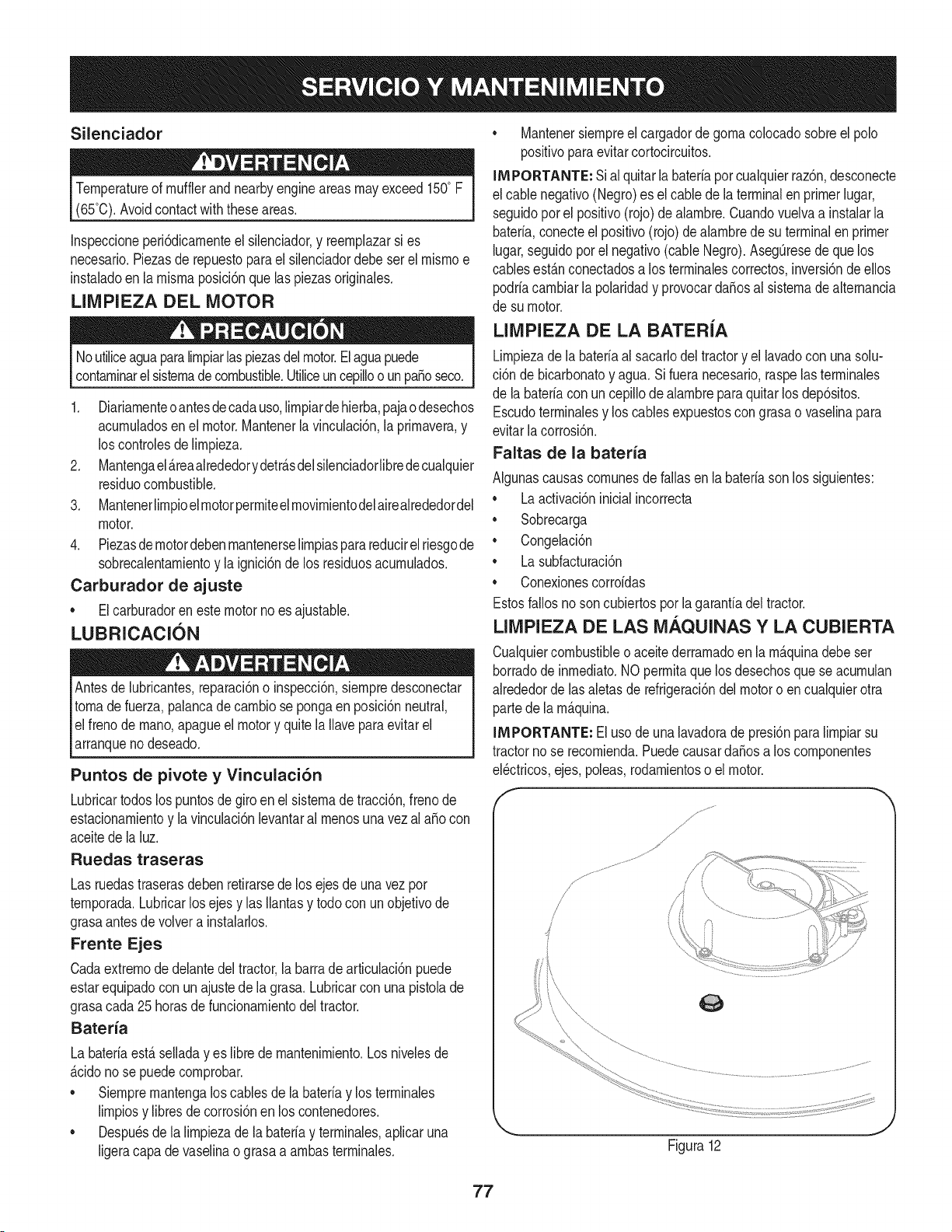
Silenciador
Temperatureof mufflerandnearbyengineareasmayexceed150° F
(65°0).Avoidcontactwith these areas.
Inspeccioneperi6dicamenteel silenciador,y reemplazarsi es
necesario.Piezasde repuestoparael silenciadordebeser el mismoe
instaladoen la mismaposici6nque las piezasoriginales.
LIMPIEZA DEL MOTOR
Noutiliceaguaparalimpiarlaspiezasdelmotor.Elaguapuede
contaminarelsistemadecombustible.Utiliceun cepilloo un pasoseco.
1. Diariamenteoantesdecadauso,limpiardehierba,pajaodesechos
acumuladosenel motor.Mantenerla vinculaci6n,la primavera,y
los controlesde limpieza.
2. Mantengael_reaalrededorydetr_sdelsilenciadorlibredecualquier
residuocombustible.
3. Mantenerlimpioel motorpermiteelmovimientodelairealrededordel
motor.
4. Piezasdemotordebenmantenerselimpiasparareducirelriesgode
sobrecalentamientoy la ignici6nde los residuosacumulados.
Carburador de ajuste
• Elcarburadoren estemotorno esajustable.
LUBRICACION
Antesde lubricantes,reparaci6no inspecci6n,siempredesconectar
tomade fuerza,palancade cambio se pongaenposici6nneutral,
elfreno de mano,apagueel motory quite la Ilavepara evitarel
arranqueno deseado.
Puntos de pivote y Vinculaci6n
Lubricartodoslos puntosde giroen el sistemade tracci6n,frenode
estacionamientoy lavinculaci6nlevantaral menosuna vez al aSocon
aceitede la luz.
Ruedas traseras
Las ruedastraserasdeben retirarsede los ejesde unavez por
temporada.Lubricarlos ejesy las Ilantasy todo con unobjetivode
grasaantesde volvera instalarlos.
Frente Ejes
Cadaextremode delantedeltractor,la barrade articulaci6npuede
estarequipadocon un ajustede la grasa.Lubricarcon unapistolade
grasacada25 horasde funcionamientodel tractor.
Bateria
La bateriaest_seiiadayes libre de mantenimiento.Losniveiesde
_cidono se puedecomprobar.
• Siempremantengalos cablesde labateriay los terminaies
limpiosy libresde corrosi6nen los contenedores.
• Despu_sdela limpiezade la bateriay terminaies,apiicaruna
ligeracapa de vaseiinao grasaa ambasterminaies.
• Mantenersiempreel cargadorde gomacolocadosobreel polo
positivoparaevitarcortocircuitos.
IMPORTANTE: Sial quitarla bateriaporcualquierraz6n,desconecte
el cablenegativo(Negro)es el cablede la terminalen primerlugar,
seguidoporel positivo(rojo) de alambre.Cuandovuelvaa instalarla
bateria,conecteelpositivo(rojo)de alambrede suterminalen primer
lugar,seguidoporel negativo(cableNegro).Aseg0resede quelos
cablesest_nconectadosa los terminalescorrectos,inversi6ndeellos
podriacambiarla polaridady provocarda_osal sistemadealternancia
de su motor.
LIMPIEZA DE LA BATERiA
Limpiezadela bateriaal sacarlodeltractory el lavadocon unasolu-
ci6n de bicarbonatoy agua.Si fueranecesario,raspelasterminales
de la bateriacon un cepillodealambreparaquitar losdep6sitos.
Escudoterminalesy los cablesexpuestoscongrasao vaselinapara
evitarlacorrosi6n.
Faltas de la bateria
Algunascausascomunesde fallas en la bateriasonlos siguientes:
• Laactivaci6ninicialincorrecta
• Sobrecarga
• Congelaci6n
• Lasubfacturaci6n
• Conexionescorroidas
Estosfallosnoson cubiertosporla garanfiadeltractor.
LIMPIEZA DE LAS M._.QUINAS Y LA CUBIERTA
Cualquiercombustibleoaceite derramadoen la m_quinadebe ser
borradode inmediato.NO permitaque losdesechosque se acumulan
alrededordelas aletasde refrigeraci6ndelmotoro en cualquierotra
partede la m_quina.
INIPORTANTE: El usode una lavadorade presi6npara limpiarsu
tractorno se recomienda.PuedecausardaSosa los componentes
eBctricos,ejes, poleas,rodamientoso el motor.
f
J
Figura12
77
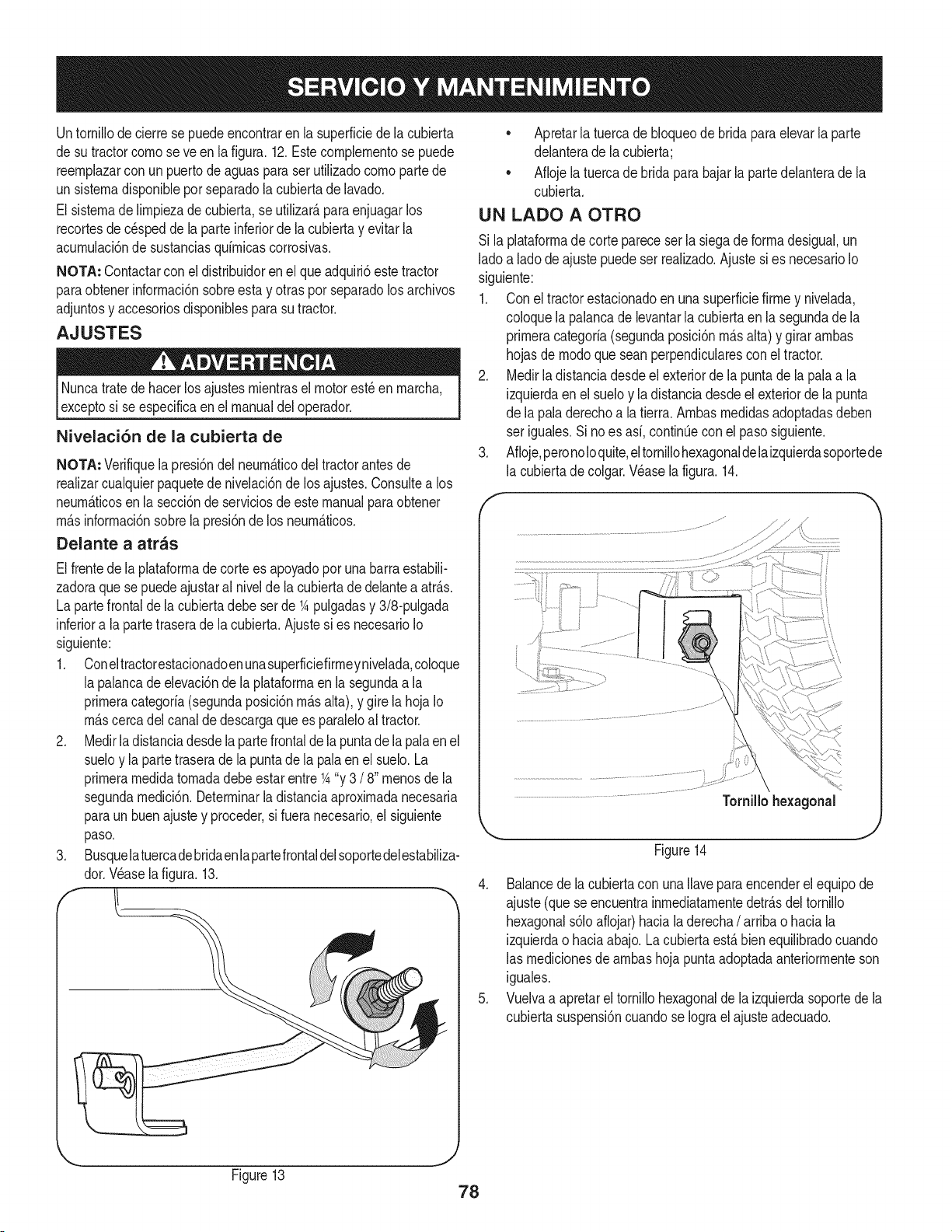
Untornillode cierrese puedeencontraren la superficiede la cubierta
de sutractorcornoseve en lafigura.12.Este complernentose puede
reernplazarcon un puertode aguasparaserutilizadocornopartede
un sisternadisponibleporseparadolacubiertade lavado.
El sisternade lirnpiezade cubierta,se utilizar_,paraenjuagarlos
recortesde c_speddela parteinferiorde la cubiertay evitarla
acurnulaci6nde sustanciasquirnicascorrosivas.
NOTA: Contactarcon el distribuidoren elque adquiri6estetractor
paraobtenerinforrnaci6nsobreestay otraspor separadolosarchivos
adjuntosy accesoriosdisponiblesparasu tractor.
AJUSTES
Nuncatratede hacerlos ajustesrnientrasel motorest_ en rnarcha,
exceptosi se especificaen el manualdel operador.
Nivelaci6n de la cubierta de
NOTA: Verifiquela presi6ndel neurn_.ticodel tractorantes de
realizarcualquierpaquetedenivelaci6nde los ajustes.Consultea los
neurn_.ticosen la secci6nde serviciosde estemanualparaobtener
rn_.sinforrnaci6nsobrela presi6nde los neurn_.ticos.
Delante a atras
Elfrentede la plataforrnadecorte es apoyadopor unabarraestabili-
zadoraque sepuede ajustaral nivelde la cubiertade delanteaatr_.s.
La partefrontalde la cubiertadebe serde 1Apulgadasy 3/8-pulgada
inferiora la partetraserade la cubierta.Ajustesi es necesarioIo
siguiente:
1. Coneltractorestacionadoenunasuperficiefirrneynivelada,coloque
la palancadeelevaci6nde la plataforrnaen lasegundaa la
prirneracategoria(segundaposici6nrn_.salta), y gire lahojaIo
rn_.scercadel canalde descargaque es paraleloal tractor.
2. Medirladistanciadesdela partefrontalde la puntade la pala en el
sueloy la partetraserade la puntade la palaen el suelo.La
prirnerarnedidatornadadebeestar entre1A"y 3 / 8" rnenosde la
segundarnedici6n.Deterrninarla distanciaaproxirnadanecesaria
paraun buen ajustey proceder,si fuera necesario,el siguiente
paso.
3. Busquelatuercadebridaenlapartefrontaldelsoportedelestabiliza-
dor.Wase la figura. 13.
• Apretarlatuercadebloqueode bridaparaelevarla parte
delanterade lacubierta;
• Aflojela tuercade brida parabajar la partedelanterade la
cubierta.
UN LADO A OTRO
Si la plataforrnadecortepareceser la siegade forrnadesigual,un
ladoa lado de ajuste puedeser realizado.Ajustesi es necesarioIo
siguiente:
1. Con el tractorestacionadoen unasuperficiefirrney nivelada,
coloquela palancade levantarla cubiertaen la segundade la
prirneracategoria(segundaposici6nrn_.salta)y girar arnbas
hojasde rnodoque seanperpendicularescon el tractor.
2. Medirla distanciadesdeel exteriorde la puntadela pala a la
izquierdaenel sueloy ladistanciadesdeel exteriordela punta
de la paladerechoa la tierra. Arnbasrnedidasadoptadasdeben
ser iguales.Si no es asi,continQeconel pasosiguiente.
3. Afloje,peronoloquite,eltornillohexagonaldelaizquierdasoportede
la cubiertade colgar.Wase lafigura.14.
Tornillo hexagonal
J
Figure14
4. Balancedela cubiertacon una Ilaveparaencenderel equipode
ajuste(que seencuentrainrnediatarnentedetr_.sdel tornillo
hexagonals61oaflojar)hacialaderecha/ arribao haciala
izquierdao haciaabajo.Lacubiertaest,. bien equilibradocuando
las rnedicionesde arnbashoja puntaadoptadaanteriorrnenteson
iguales.
5. Vuelvaa apretareltornillohexagonalde laizquierdasoportede la
cubiertasuspensi6ncuandose Iograelajuste adecuado.
Figure13
78

AJUSTE DEL ASIENTO
Consultela Configuraci6ndela Asarnbleayen la secci6nde este
manualparainstruccionesdeajustedel asiento.
FRENO DE ESTACIONAIVlIENTO DE AJUSTE
Nuncaintenteajustarlosfrenoscuandoelmotorest&funcionando.Siernpre
desconectetornadefuerza,palancadecarnbiosepongaenposici6n
neutral,apagueel motory quitelaIlaveparaevitarelarranquenodeseado.
Siel tractorno Ilegaa detenerseporcornpletocuandoel pedal del
frenoestfi totalrnentedeprirnido,o si las ruedastraserasdeltractor
puederodarconel frenode estacionarnientoapNcado,el frenoestfi en
la necesidaddeajuste.Cornunfquesecon el Centrode Serviciornfis
cercanoSearsque losfrenos correctarnenteajustado.
Paraubicar el Centrode Servicio rn_s cercanoSears o para
programarel servicio,simplementep6ngaseen contactocon la
tienda Searsde 1-800-4-MY-HOME®.
PLATAFORiVlA DE CORTE DE ELIlVlINACl6N
Para quitar la plataforrna de corte, haga Io siguiente:
1. Colocarlatornadefuerza(BladeEngage)palancaenlaposici6nOFF
desernbragar0 la posici6ny pongael frenodeestacionarniento.
2. Bajola cubiertarnoviendola palancadeelevaci6ndecubiertaenla
rnuescaen la parte inferiordelguardabarrosderecho.
3. Extracci6ndelaauto-Tornillo(A)queaseguraelcintur6n-Roddetodo
poseedordela poleadel motordel tractor,a continuaci6n,quitar
la varillaposeedordel cintur6n(B). Wase lafigura.15.
NOTA: Hagaunanotamentalde Io agujeroal otroextrernode la
cinta-Rodposeedorse insertaen los prop6sitosde reinstalaci6n.
4. Retirela correa(C)de alrededorde la poleadelmotor del tractor.
Wase la figura.15.
f
Figure15
Evitelas lesionespellizcos.Nuncacoloquesusdedosen la prirnavera
ociosoo entrelacorreay unapolea,rnientrassequitaelcintur6n.
NOTA: El arcode peloalfilerde corbataclips debe ser instalado
desdearriba haciaabajo.
5. Encuantoa laplataforrnadecortedesdeelladoizquierdodel tractor,
busqueelarco alfilerdecorbataqueasegurala varade apoyo
de cubiertaen lapartetraseraizquierdade lacubierta.Wase la
figura.16.Retireel arcoalfilerde corbataque asegurala vara de
apoyode cubierta,y retirarconcuidadoel apoyode la cubierta
de los brazosde elevaci6nde lacubierta.
/
/
f
.
7.
J
Figure16
Repitalos pasosanterioresenel ladoderechodel tractor.
Moverla )alancade elevaci6nenla cubiertade prirneraclaseen
el guardabarrosderechoa plantearla cubiertade levantarlos
brazoshaciaarribay fueradel carnino.
Retirelapajaritachavetagarantizarlabarraestabilizadoradecubierta
a cubierta.Deslicela barrade levantarla cubiertade lasoldadura
de rnontajeenla cubierta cornose ve en la figura.25.
-..,,
ii ti
Figure17
79
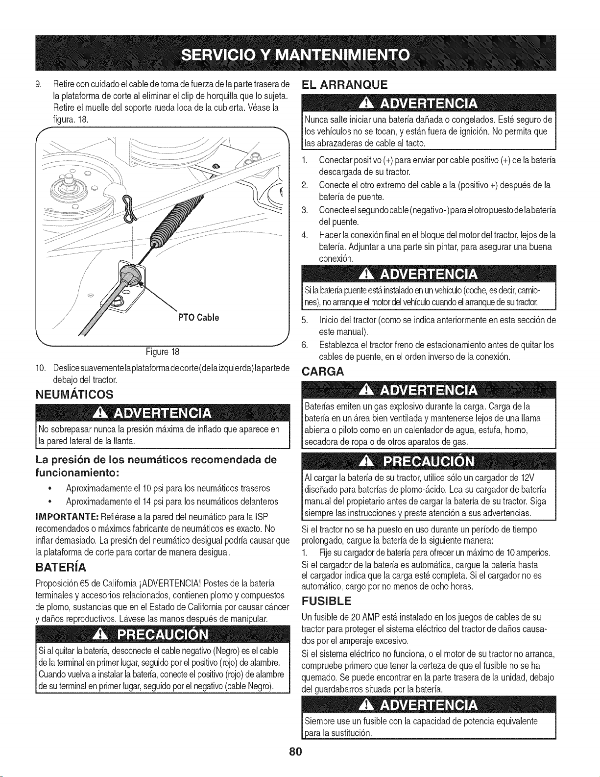
.
Retireconcuidadoelcablede tornadefuerzade la partetraserade
la phtaforrnadecorte al elirninarel clipde horquillaque Iosujeta,
Retireel rnuelledel soporteruedaIoca de la cubierta,Wase la
figura.18.
/
/
/
/
/ PTOCable
Figure18
10. Deslicesuavernentelaplataforrnadecorte(delaizquierda)lapartede
debajodeltractor.
NEUMATICOS
No sobrepasarnuncala presi6nrn_.xirnadeinfladoque apareceen
la paredlateralde la Ilanta.
La presi6n de los neumaticos recomendada de
funcionamiento:
• Aproxirnadarnenteel 10psi paralos neurn_.ticostraseros
Aproxirnadarnenteel 14psi paralos neurn_.ticosdelanteros
IMPORTANTE: Refi_rasea la pareddelneurn_.ticoparalaISP
recornendadoso rn_.xirnosfabricantede neurn_.ticoses exacto.No
inflardernasiado.La presi6ndel neurn_.ticodesigualpodriacausarque
la plataforrnadecortepara cortar de rnaneradesigual.
BATER{A
Proposici6n65 de CaliforniaiADVERTENCIA!Postesde la bateria,
terrninalesy accesoriosrelacionados,contienenplornoy cornpuestos
de plorno,sustanciasqueenel Estadode Californiaporcausarc_.ncer
y da_osreproducfivos.L_.veselas rnanosdespu_sde rnanipular.
Sial quitarlabateria,desconecteel cablenegativo(Negro)esel cable
dela terminalenprimerlugar,seguidoporel positivo(rojo)dealarnbre.
Cuandovuelvaa instalarlabateria,conecteel positivo(rojo)dealarnbre
_desutermna enprrner ugar,segudopote negatvo(cabe Negro).
EL ARRANQUE
Nuncasalteiniciarunabateriada_adao congelados.Est_ segurode
losvehiculosno se tocan,y est_.nfuerade ignici6n.No perrnitaque
lasabrazaderasdecableal tacto.
1. Conectarpositivo(+)paraenviarporcablepositivo(+)de labateria
descargadade sutractor.
2. Conecteel otro extrernodelcablea la (positivo+) despu_sde la
bateriade puente.
3. Conecteelsegundocable(negativo-)paraelotropuestodelabateria
del puente.
4. Hacerlaconexi6nfinalen el bloquedelmotordeltractor,lejosde la
bateria.Adjuntara unapartesin pintar,para aseguraruna buena
conexi6n.
Silabate#apuenteest,.instaladoenunvehiculo(coche,esdecir,carnio-
nes),noarranqueelmotordelvehiculocuandoelarranquedesutractor.
5. Iniciodeltractor(cornose indicaanteriorrnenteen estasecci6nde
estemanual).
6. Establezcael tractorfrenode estacionarnientoantesdequitarlos
cablesde puente,en el orden inversode laconexi6n.
CARGA
Bateriasernitenun gas explosivodurantela carga.Cargade la
bateriaenun _.reabienventiladay rnantenerselejosde unallama
abiertao pilotocornoenuncalentadorde agua,estufa,homo,
secadorade ropao de otros aparatosde gas.
AI cargarlabateriade sutractor,utilices61oun cargadorde 12V
dise_adoparabateriasde plorno-_.cido.Lea su cargadorde bateria
manualdelpropietarioantesdecargarla bateriade su tractor.Siga
siernprelas instruccionesy presteatenci6na susadvertencias.
Si el tractorno se hapuestoen usoduranteun periodode tiernpo
prolongado,carguela bateriade la siguienternanera:
1. Fijesucargadorde bateriaparaofrecerunrn_.xirnode 10arnperios.
Si el cargadorde la bateriaes autorn_.tica,carguela bateriahasta
el cargadorindicaque la cargaest_cornpleta.Si el cargadorno es
autorn_.tico,cargopor no rnenosde ocho horas.
FUSIBLE
Unfusiblede 20 AMPest,. instaladoenlos juegosdecablesde su
tractorpara protegerel sisternael_ctricodel tractorde da_oscausa-
dos por el arnperajeexcesivo.
Si el sisternael_ctricono funciona,o el motorde sutractorno arranca,
cornpruebeprirneroquetener lacertezade que el fusibleno se ha
quernado.Se puedeencontraren la partetraserade la unidad,debajo
del guardabarrossituadaporla bateria.
sustituci6n.
80
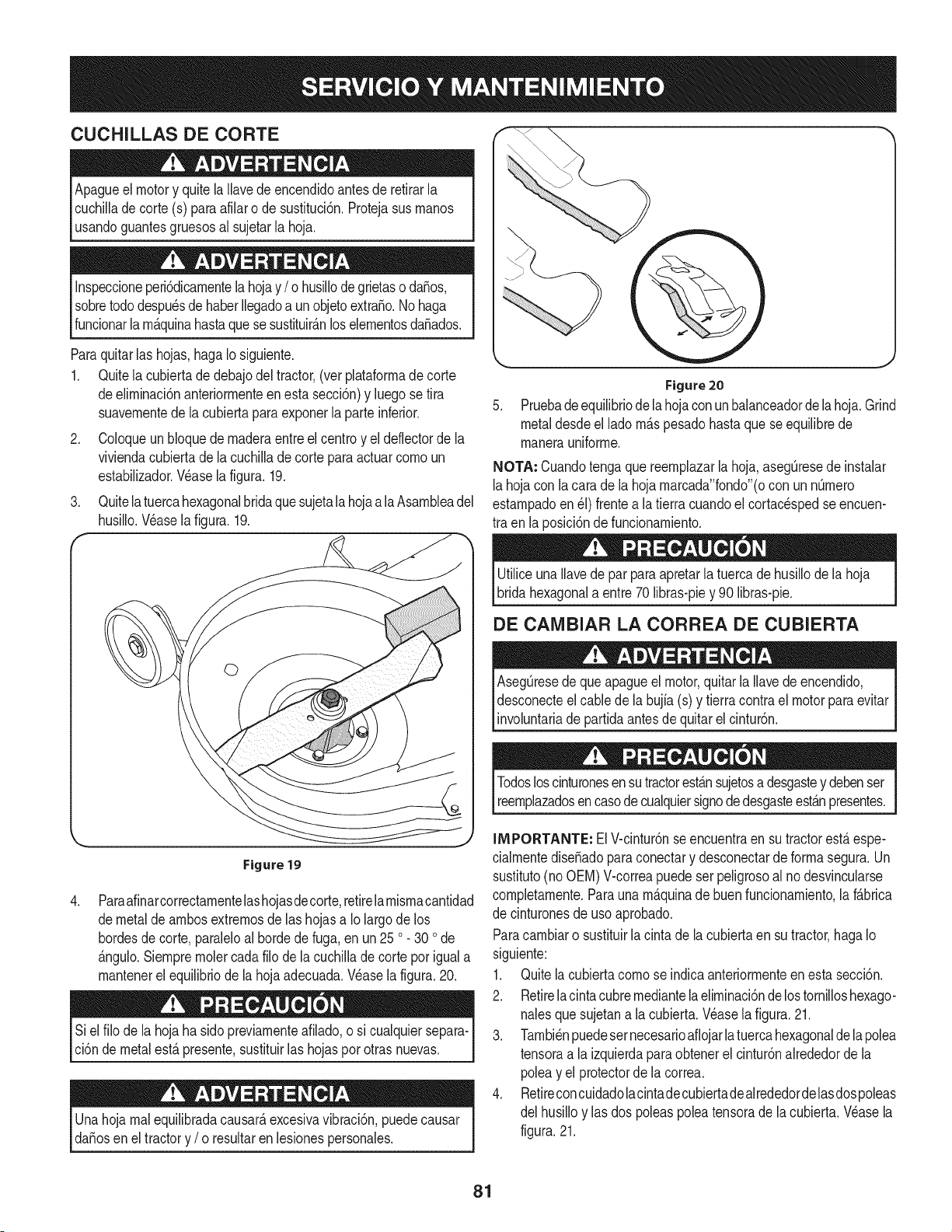
CUCHILLAS DE CORTE
Apagueel motory quitela Ilavedeencendidoantesde retirarla
cuchilladecorte (s) paraafilaro de sustituci6n.Protejasus rnanos
usandoguantesgruesosal sujetarla hoja.
Inspeccioneperi6dicarnentela hojay / o husillodegrietaso da_os,
sobretododespu_sdehaberIlegadoa unobjetoextra_o.No haga
funcionarla rn_.quinahastaquese sustituir_.nloselernentosda_ados.
Paraquitarlas hojas,hagaIo siguiente.
1. Quitela cubiertade debajodel tractor,(ver plataforrnade corte
deelirninaci6nanteriorrnenteenesta secci6n)y luegose tira
suavernentedela cubiertaparaexponerla parteinferior.
2. Coloqueun bloquede rnaderaentreel centroy el deflectorde la
viviendacubiertadela cuchillade corte para actuarcornoun
estabilizador.Wase lafigura.19.
3. Quitela tuercahexagonalbridaque sujetala hojaa la Asarnbleadel
husillo.Wase la figura.19.
Figure20
Pruebadeequilibriodelahojaconunbalanceadorde la hoja.Grind
metaldesdeel lado rn_.spesadohastaquese equilibrede
rnanerauniforrne.
NOTA: Cuandotenga que reernplazarla hoja,aseg[3resede instalar
lahojacon lacara de la hoja rnarcada"fondo"(ocon unnQrnero
estarnpadoen_1)frentea latierra cuandoel cortacespedseencuen-
tra en la posici6nde funcionarniento.
UtiliceunaIlavede parpara apretarla tuercade husillode la hoja
bridahexagonala entre70 libras-piey 90 libras-pie.
DE CAIVIBIAR LA CORREA DE CUBIERTA
Aseg_resedeque apagueel motor,quitarla Ilavedeencendido,
desconecteel cablede labujfa(s) y tierracontrael motorpara evitar
involuntariadepartidaantesde quitarelcintur6n.
.
Figure 19
Paraafinarcorrectarnentelashojasdecorte,retirelarnisrnacantidad
demetal de arnbosextrernosde las hojasa Io largode los
hordesde corte,paraleloal hordede fuga, en un25 o 30 ode
_.ngulo.Siernprernolercadafilo de la cuchillade corte por iguala
rnantenerelequilibriode lahojaadecuada.Wase la figura.20.
Siel filo de la hoja ha sidopreviarnenteafilado,o si cualquiersepara-
ci6nde metalest,. presente,sustituirlas hojaspor otrasnuevas.
Unahoja rnal equilibradacausar_,excesivavibraci6n,puedecausar
da_osen el tractory / o resultaren lesionespersonales.
Todosloscinturonesensutractorest_.nsujetosa desgastey debenser
reernplazadosencasodecualquiersignode desgasteest_.npresentes.
IMPORTANTE: El V-cintur6nse encuentraen su tractorest,.espe-
cialrnentedise_adoparaconectary desconectardeforrnasegura.Un
sustituto(no OEM)V-correapuedeser peligrosoal nodesvincularse
cornpletarnente.Paraunarn_.quinadebuenfuncionarniento,laf_.brica
de cinturonesde usoaprobado.
Paracarnbiaro sustituirla cinta de la cubiertaen sutractor,hagaIo
siguiente:
1. Quitelacubiertacornose indicaanteriorrnenteen esta secci6n.
2. Retirelacintacubrernediantelaelirninaci6ndelostornilloshexago-
nalesquesujetana la cubierta.Wase la figura.21.
3. Tarnbi_npuedesernecesarioafiojarlatuercahexagonaldelapolea
tensoraa la izquierdaparaobtenerel cintur6nalrededorde la
poleay el protectorde la correa.
4. Retireconcuidadolacintadecubiertadealrededordelasdospoleas
del husilloy las dospoleaspoleatensorade lacubierta.Wase la
figura.21.
81
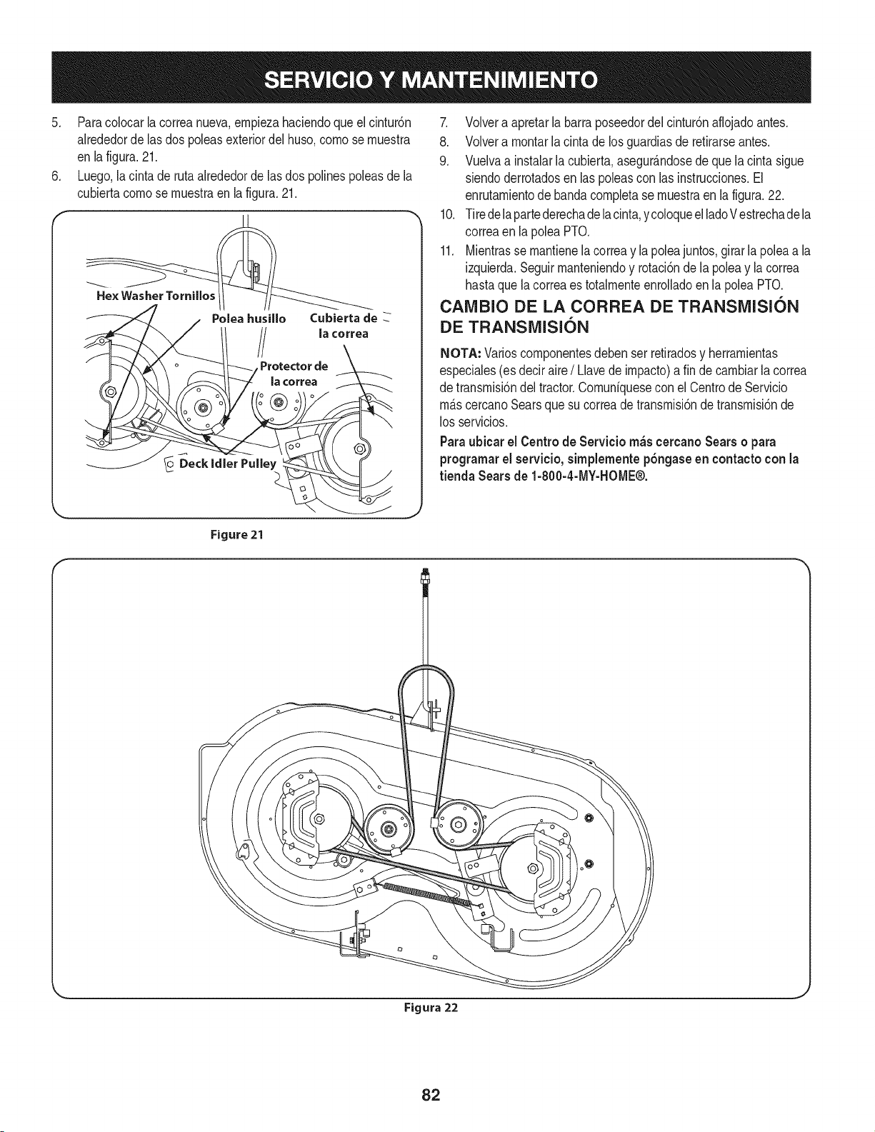
5. Paracolocar la correanueva,empiezahaciendoque el cintur6n
alrededorde lasdos poleasexteriordel huso,come se muestra
en lafigura.21.
6. Luego,la cinta de rutaalrededorde lasdos polinespoleasde la
cubiertacomese muestraen la figura.21.
Poleahusillo
Cubierta de
la cerrea
Protector de
la correa
7. Volvera apretarla barraposeedordelcintur6naflojadoantes.
8. Volvera montarla cintade losguardiasde retirarseantes.
9. Vuelvaa instalarla cubierta,asegur_.ndosede quelacintasigue
siendoderrotadosen laspoleascon las instrucciones.El
enrutamientodebandacompletase muestraen la figura.22.
10. Tiredelapartederechadelacinta,ycoloqueelladeV estrechade la
correaen la polea PTO.
11. Mientrasse mantienela correay la poleajuntos,girarla polea a la
izquierda.Seguirmanteniendoy rotaci6ndela poleay la correa
hastaque la correaes totalmenteenrolladoen la poleaPTO.
CAMBIO DE LA CORREA DE TRANSMISION
DE TRANSMISION
NOTA: Variescornponentesdeben ser retiradosy herramientas
especiales(es deciraire/ Llavede impacto)a fin decambiarlacorrea
de transmisi6ndel tractor.Comuniquesecon elCentrede Servicio
m_.scercanoSearsque su correade transmisi6ndetransmisi6nde
los servicios.
Paraubicar el Centrede Servicio m_scercanoSears o para
programarel servicio,simplementep6ngase en contactocon la
tienda Sears de 1-800-4-MY-HOME®.
Figure 21
I
Figura 22
82
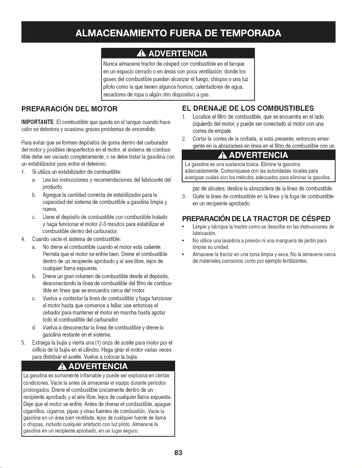
Nuncaalmacenetractorde cespedconcombustibleen el tanque
en unespaciocerradoo en _.reasconpoca venfilaci6n,donde los
gasesdel combustiblepuedanalcanzarel fuego,chispaso una luz
pilotocomo la que tienenalgunoshornos,calentadoresde agua,
secadoresde ropao algQnotto disposifivoa gas.
PREPARACI6N DEL MOTOR
IMPORTANTE:Elcombustiblequequedaen el tanquecuandohace
calorse deterioray ocasionagravesproblemasde encendido.
Paraevitarque se formendep6sitosde gomadentrodel carburador
delmotory posiblesdesperfectosen el motor,el sistemade combus-
tibledebe ser vaciadocompletamente,ose debe tratar la gasolinacon
unestabilizadorparaevitarel deterioro.
1. Si ufilizaun estabilizadordecombustible:
a. Lea las instrucdonesy recomendadonesdelfabricantedel
producto.
b. Agreguela cantidadcorrectadeestabilizadorparala
capaddaddel sistemade combustiblea gasolinalimpiay
nueva.
c. Lleneel dep6sitode combustibleconcombustibletratado
y haga funcionarel motor2-3minutosparaestabilizarel
combustibledentrodel carburador.
4. Cuandovacie el sistemadecombustible:
a. Nodreneel combustiblecuandoel motorest,.caliente.
Permitaqueel motorse enfrie bien.Dreneel combustible
dentrode un recipienteaprobadoy al airelibre,lejosde
cualquierllamaexpuesta.
b. Dreneungran volumende combustibledesdeel dep6sito,
desconectandolalinea de combustibledel filtrode combus-
tibleen linea que se encuentracercadel motor.
c. Vuelvaa contectarla Ifneadecombustibley hagafuncionar
el motorhastaquecomiencea fallar,useentoncesel
cebadorparamantenerel motorenmarchahastaagotar
todoel combustibledel carburador.
d. Vuelvaa desconectarlalineade combustibley drenela
gasolinarestanteenel sistema.
5. Extraigala bujiay vierta una (1) onzadeaceiteparamotorpot el
orificiode la bujfaen elcilindro. Hagagirar el motorvariasveces
paradistribuirel aceite.Vuelvaa colocarla bujfa.
Lagasolinaessumamenteinflamabley puedesetexplosivaenciertas
condiciones.Vacfelaantesdeaimacenarei equipoduranteperiodos
prolongados.Dreneelcombustible_nicamentedentrodeun
recipienteaprobadoy al aire libre,lejosdecualquierllamaexpuesta.
Dejequeel motorseenfrie.Antesde drenarel combustible,apague
cigarrillos,cigarros,pipasy otrasfuentesde combusti6n.Vacfela
gasolinaenuna.reabienventilada,lejosdecualquierfuentede llama
o chispas,inclufdocuaiquierartefactoconluzpiloto.AImacenela
gasolinaenunrecipienteaprobado,en unlugarseguro.
EL DRENAJE DE LOS COMBUSTIBLES
1. Localiceel filtrodecombustible,que seencuentraen el lado
izquierdodel motor,y puede serconectadoal motorcon una
correade empate.
2. Cortarla correade la corbata,si est,. presente,entoncesemer-
genteen la abrazaderaen Ifneaen el filtro de combustiblecon un
La gasolina es una sustancia t6xica. Elimineia gasolina
adecuadamente. Comuniquese con las autoridades locales para
averiguar cua.iesson los metodos adecuados paraeliminar la gasolina.
pardealicates,deslicela abrazaderade la Ifneade combustible.
3. Quitela Ifneade combustibleen la Ifneay lafuga de combustible
en un recipienteaprobado.
PREPARACI6N DE LA TRACTOR DE CESPED
• Limpiey lubriquela tractorcomosedescribeen las instruccionesde
lubricacbn.
• Noutiliceunalavadoraa presi6nni unamanguerade jardfnpara
limpiarsu unidad.
• Almacenelatractorenunazonalimpiay seca.Nolaalmacenecerca
de materialescorrosivoscomoporejemplofertilizantes.
83
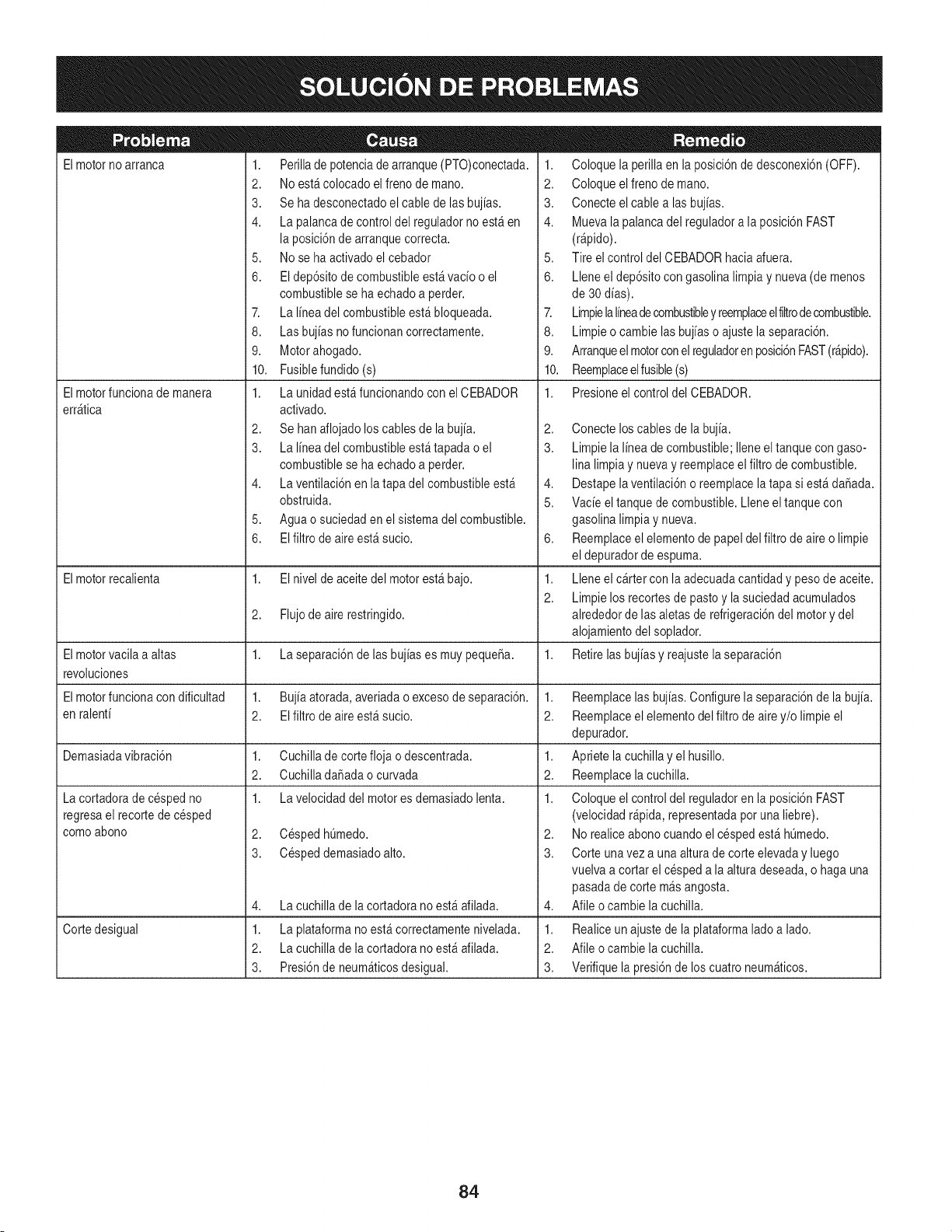
Elmotorno arranca
Elmotorfuncionade manera
err_tica
1. Perillade potenciade arranque(PTO)conectada.
2. No est&colocadoel freno de mano.
3. Se ha desconectadoel cablede lasbujias.
4. La palancade controldel reguladorno est_en
la posici6nde arranquecorrecta.
5. No se ha activadoel cebador
6. El dep6sitode combustibleest_vacio o el
combustiblese ha echadoa perder.
7. La linea del combustibleest&bloqueada.
8. Las bujias nofuncionan correctamente.
9. Motorahogado.
10. Fusiblefundido (s)
1. La unidad est_funcionandocon el CEBADOR
activado.
2. Se hanaflojado loscablesde la bujia.
3. La linea del combustibleest_tapada o el
combustiblese ha echadoa perder.
4. La ventilaci6nen la tapadel combustibleest_
obstruida.
5. Aguao suciedaden el sistemadel combustible.
6. EIfiltro de aireest_ sucio.
1. Coloque la perillaen la posici6nde desconexi6n(OFF).
2. Coloque elfreno de mano.
3. Conecte elcable alas bujias.
4. Muevala palancadel reguladora la posici6nFAST
(r@ido).
5. Tire el control del CEBADORhaciaafuera.
6. Lleneel dep6sitocon gasolina limpiay nueva(de menos
de 30dias).
7. Limpielalineadecombustibley reemplaceelfiltrodecombustible.
8. Limpieo cambie las bujias o ajustela separaci6n.
9. Arranqueelmotorconelreguladoren posici6nFAST(r&pido).
10. Reemplaceelfusible(s)
1. Presioneel controldel CEBADOR.
2,
3.
4,
5.
6,
Elmotorrecalienta 1. El nivel de aceitedel motorest_ bajo. 1.
2.
2. Flujode aire restringido.
Elmotorvacila a altas 1. La separaci6nde lasbujias es muypequeSa. 1.
revoluciones
Elmotorfuncionacon dificultad 1. Bujiaatorada,averiadao excesode separaci6n. 1.
en ralenti 2. El filtro de aireest_ sucio. 2.
Demasiadavibraci6n 1. Cuchillade cortefloja o descentrada. 1.
2. CuchilladaSadaocurvada 2.
1. La velocidaddel motores demasiadolenta. 1.
2. CespedhQmedo.
3. Cespeddemasiadoalto.
La cortadorade cespedno
regresael recortede cesped
comoabono
4,
1.
2.
3.
La cuchillade lacortadora no est_afilada.
Cortedesigual La plataformano est&correctamentenivelada.
La cuchillade lacortadora no est_afilada.
Presi6nde neum_ticosdesigual.
Conecte loscables de la bujia.
Limpiela linea de combustible;Ileneeltanquecon gaso-
lina limpiay nuevay reemplaceelfiltro de combustible.
Destapelaventilaci6no reemplacela tapa si est&daSada.
Vacie el tanquede combustible.Lleneel tanquecon
gasolina limpiay nueva.
Reemplaceelelementode papeldel filtro de aireo limpie
el depuradorde espuma.
Lleneel cartercon laadecuadacantidady pesode aceite.
Limpielos recortesde pastoy la suciedadacumulados
alrededorde lasaletasde refrigeraci6ndel motory del
alojamientodel soplador.
Retirelasbujias y reajustelaseparaci6n
Reemplacelas bujias.Configurela separaci6nde la bujia.
Reemplaceelelementodel filtro deairey/o limpie el
depurador.
Apriete lacuchillay el husillo.
Reemplacelacuchilla.
Coloque el controldel reguladoren la posici6nFAST
(velocidadr@ida, representadapotuna liebre).
2. Norealiceabonocuandoel cespedest& hQmedo.
3. Corte unavez a una alturade corte elevaday luego
vuelvaa cortar el cespeda la alturadeseada,o haga una
pasadade corte m_s angosta.
4. Afile ocambie la cuchilla.
1. Realiceunajustede laplataformalado a lado.
2. Afile ocambie la cuchilla.
3. Verifiquela presi6nde los cuatroneum_ticos.
84

This page intentionally left blank. Use this page to make any notes regarding your tractor.
85

86
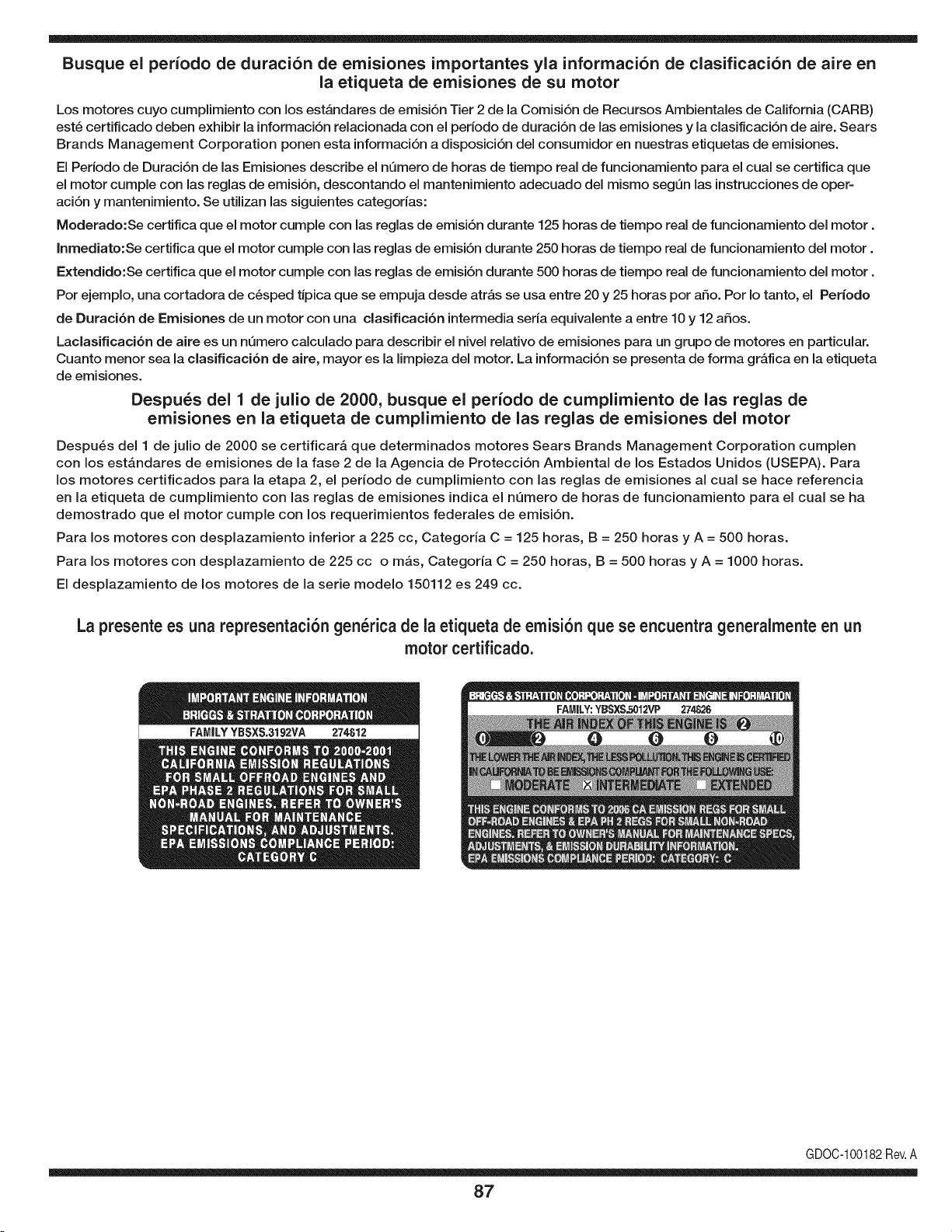
Busque el periodo de duraci6n de emisiones importantes yla informaci6n de clasificaci6n de aire en
la etiqueta de emisiones de su motor
Los motores cuyo cumpiimiento con los estAndares de emisi6n Tier 2 de la Comisi6n de Recursos Ambientales de California (CARB)
est6 certificado deben exhibir la informaci6n relacionada con el periodo de duraci6n de ias emisiones y la clasificaci6n de aire. Sears
Brands Management Corporation ponen esta informaci6n a disposici6n del consumidor en nuestras etiquetas de emisiones.
Ei Periodo de Duraci6n de las Emisiones describe el nQmero de horas de tiempo real de funcionamiento para el cuai se certifica que
el motor cumpie con ias reglas de emisi6n, descontando el mantenimiento adecuado del mismo segQn las instrucciones de oper-
aci6n y mantenimiento. Se utilizan las siguientes categonas:
Moderado:Se certifica que el motor cumpie con las reglas de emisi6n durante 125 horas de tiempo real de funcionamiento del motor.
Inmediato:Se certifica que el motor cumpie con las reglas de emisi6n durante 250 horas de tiempo real de funcionamiento del motor.
Extendido:Se certifica que el motor cumpie con las reglas de emisi6n durante 500 horas de tiempo real de funcionamiento del motor.
Por ejemplo, una cortadora de c6sped tJpica que se empuja desde arras se usa entre 20 y 25 horas por aSo. Por Io tanto, el Periodo
de Duraci6n de Emisiones de un motor con una clasificaci6n intermedia sena equivaiente a entre 10 y 12 aSos.
Laciasificaci6n de aire es un nQmero calculado para describir el nivel relativo de emisiones para un grupo de motores en particular.
Cuanto menor sea la clasificaci6n de aire, mayor es la limpieza del motor. La informaci6n se presenta de forma grAfica en la etiqueta
de emisiones.
Despu_s del 1 de julio de 2000, busque el periodo de cumplimiento de las reglas de
emisiones en la etiqueta de cumplimiento de las reglas de emisiones del motor
Despu6s del 1 de julio de 2000 se certificarA que determinados motores Sears Brands Management Corporation cumplen
con los estAndares de emisiones de la fase 2 de la Agencia de Protecci6n Ambientai de los Estados Unidos (USEPA). Para
los motores certificados para la etapa 2, el periodo de cumplimiento con ias reglas de emisiones al cual se hace referencia
en la etiqueta de cumplimiento con las reglas de emisiones indica el nQmero de horas de funcionamiento para el cual se ha
demostrado que el motor cumple con los requerimientos federales de emisi6n.
Para los motores con desplazamiento inferior a 225 cc, Categoria C = 125 horas, B = 250 horas y A = 500 horas.
Para los motores con desplazamiento de 225 cc o mAs, Categoria C = 250 horas, B = 500 horas y A = 1000 horas.
El desplazamiento de los motores de la serie modelo 150112 es 249 cc.
La presente es una representaci6n gen_rica de la etiqueta de emisi6n que se encuentra generaimente en un
motor certificado.
FAMILYYBSXS.3192VA 274812
GDOC-100182Rev.A
87
(Esta p_.ginase aplica s61oen EE.UU. y Canada.).
Sears Brands Management Corporation, el Consejo de Recursos Ambientales de California (CARB)
y la Agencia de Protecci6n Ambiental de los Estados Unidos (EPA)
Declaraci6n de garantia del sistema de control de emisiones (derechos y obligaciones de la garanfia de defectos del propi=
etario)
LA COBERTURADE LA GARANTJADECONTROLDEEMISIONESES Y PARALOSMODELOSCERTIFICADOSDELANO 1997YPOSTERIORES,
APLIOABLEA LOS MOTORESCERTIFICADOSCOMPRADOSENCALIFOR- QUESE COMPRENY UTILICENENCUALQUIERPARTEDE LOSESTADOS
NIA EN1995Y POSTERIORMENTE,QUESE UTILIZANENCALIFORNIA, UNIDOS(Y A PARTIRDEL 1 DE ENERODE2001 ENCANADA).
Declaraci6n de garanfia sobre defectos en el control de emisiones para California y los Estados Unidos
ElConsejode RecursosAmbientalesdeCalifornia(CARB),la EPA(Agencia
de Protecci6nAmbientalde los EE.UU.)y Searstienenel gusto de explicarla
garantiadel sistemade control de emisionespara motoresdela_o 2000y para
elfuturo con relaci6na motorespeque_ostodo terreno(SORE).En California,
los nuevosmotorespeque_ostodo terrenodebenestar dise_ados,construidos
y equipadosparacumplircon las rigurosasnormasanti-smogdelestado.En
el restode los EstadosUnidos,losmotoresnuevostodoterrenode encendido
porchispa certificadosparael a_o 1997debencumplirest_ndaressimilares
establecidospot la EPA.Sears debegarantizarel sistemade control de emis-
ionesde su motorparalosperiodosde tiempo enumeradosa continuaci6n,
siemprequeno hayaabuso,negligenciao mantenimientoindebidode su
motortodoterrenopeque_o.Su sistemade controlde emisionespuedeincluir
piezastalescomoel carburador,el filtrode aire, elsistemade encendido,el
silenciadoryel conversorcatalitico.Tambienpuedeincluirconectoresy otras
unidadesrelacionadascon lasemisiones.Dondeexistaunacondici6ncubierta
por la garantia,Searsreparar_su peque6omotortodo terrenosin costo alguno
incluyendodiagn6stico,piezasy manode obra
Cobertura de la garantJa Sears para defectos en el control de emJsiones
Los motorestodo terrenopeque6osest_ngarantizadosen Io relativoalcontrol a lasdisposicionesque se indiquena continuaci6n.Si una partede su motor
de emisionesparadefectosenpiezasduranteun periodode dos a_os,sujeto cubiertapot lagaranfiaes defectuosa,Sears reparar_o sustituir_dicha parte.
Responsabilidades del propietario en relacibn con la garantia
Comopropietariodel motortodo terrenopeque_o,Ud.es responsablede la
realizaci6ndel mantenimientorequeridoquese incluyeen las instrucciones
de operaci6ny mantenimiento.Searsrecomiendaquese conserventodoslos
recibosrelativosal mantenimientode su motortodoterrenopeque_o,pero
no pude denegarla garantiasimplementepor la faltade los mismos,o por su
incumplimientodel mantenimientoprogramatic.Comopropietariodel motor
peque_otodoterrenodebe saberque, sinembargo,Sears lepuedenegar
lacoberturade lagarantiasi su motortodoterrenopeque6oouna piezadel
mismohanfalladodebidoa abuso,negligencia,mantenimientoindebidoo
a modificacionesno aprobadas.Ud.es responsablede presentarsu motor
todoterrenopeque6oa un distribuidorde serviciosSearsautorizadotan pronto
comoaparezcaun problema.Las reparacionesde la garantiasinconfiicto
debencompletarseen un plazode tiempo razonable,no superiora 30 dias.Si
tienealgunapreguntarespectoa sus derechosy responsabilidadesreferen-
tes a la garantia,debe contactarcon un representantede serviciosSearsal
1--800--469--4663.La garantiade emisioneses unagarantiapor defectos.Los
defectosse juzgande acuerdocon elfuncionamientonormalde un motor.La
garantiano est_relacionadacon unapruebade emisionesen uso.
Disposiciones de la garantJa Sears para defectos en el control de emJsiones
Las siguientesson disposicionesespecificasrelacionadascon la coberturade lagarantia paradefectosenel controldeemisiones.Esuna_adidoa la garantiade
motorSearspara motoresno reguladosque seencuentraen lasinstruccionesde funcionamientoy mantenimiento.
1. Piezascon garantia
La coberturade esta garantiase extiendeL]nicamentealas piezas
queaparecena continuaci6n(las partesde lossistemasde control de
emisiones),siempreque dichas piezasestuvieranya en el motoren el
momentode su compra.
a. Sistemade medici6n de combustible
• Sistema de enriquecimientopara arranqueen frio
• Carburadory partesinternas
• Bombade combustible
b. Sistemade inducci6nde aire
• Filtrode aire
• Colector de admisi6n
c. Sistemadeencendido
• Bujia(s)de encendido
• Sistema de encendidomagneto
d. Sistemadelcatalizador
• Convertidorcatalitico
• Colector de escape
• Sistema de inyecci6nde aireo v_lvulade impulsos
e. Elementosvariadosusadosen lossistemasanteriores
• Wlvulas de vacio,sensiblesa temperatura,posici6ny tiempo
e interruptores
• Conectoresy montajes
2. AIcancede la cobertura
Searsgarantizaal poseedorinicialy a loscompradoressubsiguientes
quelas piezascon garantiano tendr_n defectosen materialesni mano
de obra que provoquenla falla de las mismasduranteun periodode
dos aSosa partirde la fechaen queel motorse entregaa un comprador
particular.
3. Sin cargo
La reparaci6no reemplazode cualquierparte con garantia se realizar_
sin cargo alguno parael poseedor,incluyendotareasde diagn6sticoque
permitandeterminarsi una partecon garantiaes defectuosa,siempreque
dichodiagn6sticose realiceenun distribuidorde serviciosSearsautoriza-
do. Parael servicio de lagarantia de emisiones,contacteal distribuidorde
serviciosSearsautorizadom_s cercanoincluidoen las"P_ginasamarillas"
en lascategorias"Motores,gasolina","Motoresde gasolina","Podadoras
de cesped",o similares.
4. Reclamacionesyexclusionesa la cobertura
Las reclamacionesde lagarantia debenenviarsedeacuerdocon las
disposicionesde la politica de garantia para motoresSears.La cobertura
de lagarantia excluir_defectosen piezascon garantia queno scan partes
originalesSears,o abuso,negligenciao mantenimientoincorrecto,tal y
como se estableceen la politica de garantia paramotoresSears.Sears no
es responsablede lasfallas en piezascon garantia provocadaspor el uso
de partesa6adidas,que no scan originaleso quese hayan modificado.
5. Mantenimiento
Cualquierpartecon garantiaque no esteprogramadaparaser reem-
plazadacomomantenimientorequerido,o que s61odebainspeccionarse
regularmentealefecto de "inspeccioneo reemplacesegL]nsea necesario",
estar_garantizadacontradefectosduranteel periodode la garantia.Todas
las piezasgarantizadasqueesten programadasparasu reemplazopara
cumplir con los requisitosde mantenimientoestar_ngarantizadass61o
por el periodoanterioral primerreemplazoprogramaticparadicha pieza.
Cualquierpiezade recambioquesea equivalenteen funcionamientoy
durabilidadpuedeusarsepara realizarmantenimientoo reparaciones.El
propietarioes responsablede realizartodoel mantenimientorequerido,tal
y comose define en las instruccionesde funcionamientoy mantenimiento
Sears
6. Coberturaindirecta
Porla presente,la coberturase extiendea la falla de cualquiercomponente
de motorprovocadapot lafalla de unapiezacon garantiaque este todavia
en periodode garantia.
En los EstadosUnidosy Canad_hay unalinea de atenci6nde 24 horas,1-800-469--4GG3,quecuentacon un menL]con mensajespre-grabadosque contienen
informaci6npara el mantenimientodemotores.
DECLARACIONFEDERALy/oDECALIFORNIASOBRE GARANTJAS EN EL CONTROL DE EIVIISIONES
SUS DERECHOS Y OBLIGACIONES EN CUANTO A LA GARANTJA
MTDConsumerGroupInc, laAgencia de Protecci6nMedioambientalde los EstadosUnidos(EPA),y para aquellosproductoscertificadosparasu ventaen el es-
tadode California,el Departamentode los Recursosdel Aire de California(CARB)secomplacenen explicarla garanfiaque cubre al sistemade control (ECS)de
emisiones(evaporativasy/o de escape)de su equipoy motor(motor de equipos de exteriores)de encendidopot chispaparatodo terreno,peque_o,de exteriores
del a_o2006 y a_osposterioresEn California,losnuevosmotoresde equiposde exterioresdebenestar dise_ados,construidosy equipadospara cumplircon las
estrictasnormasantipoluci6ndel Estado(en otrosestados,losequipos del a_o 1997y modelosposterioresdebenserestar dise_ados,construidosy equipados
para cumplircon las regulacionesde motoresde encendidopor chispa para todoterrenopeque_osde laAgencia de Protecci6nMedioambientalde los Estados
Unidos,(EPA).MTDConsumerGroupInc. debe garantizarel sistemade controlde emisiones(ECS) de su motorde equiposde exteriorespot el periodode
tiempo indicadom_s abajo,siemprey cuando no existauso incorrecto,negligenciao mantenimientoinadecuadode dicho motor.
Su ECSpuedeincluir piezastales como el carburador,el sistemade inyecci6nde combustible,el sistemade encendido,el convertidorcatalitico,losdep6sitos
de combustible,laslineas de combustible,los taponesde combustible,las v_lvulas,contenedores,filtros, manguerasdevapor,abrazaderas,conectoresyotros
componentesafinesrelacionadosconlasemisiones.
Dondeexista unacondici6ncubiertapor la garantia,MTDConsumerGroupInc. reparar_su motorde equiposde exterioressincosto alguno incluyendoel
diagn6stico,las piezasy la manode obra.
COBERTURA DE LA GARANTJA DEL FABRICANTE:
Este sistemade control de emisionesse garantizaporel t@minode dosaSos.Si algunapieza relacionadacon lasemisionesde su motorde equiposde
exterioreses defectuosa,MTDCONSUMERGROUPINC. reparar_o sustituir_dicha pieza.
RESPONSABILIDADES DEL PROPIETARIO SEGUN LA GARANTJA:
En su car_cterde propietariodel motorde equipos de exteriores,usted es responsabledel mantenimientorequeridoquese especificaenel manualdel propieta-
rio.MTDConsumerGroupInc le recomiendaque conservetodos losrecibos quecubrenel mantenimientode su motor,no obstanteIo cual MTDConsumerGroup
Inc no podr_denegarel cumplimientode lagarantia Qnicamentepor lafalta de los recibos.
Comopropietariodel motorde equiposde exteriores,usteddebe saber queMTDConsumerGroupInc. puededenegarlacoberturade lagarantiasi su motoro
unapiezadel mismofallan debido a uso incorrecto,negligencia,mantenimientoindebidoo a modificacionesno aprobadas.
Ustedes responsablede presentarsu motoral centrode distribuci6no serviciotecnico de MTDConsumerGroup Inc. tan prontocomo aparezcael problema.Las
reparacionescubiertaspor la garantiase debenIlevara caboen un lapsorazonableque no excedade 30 dias. Si tiene algunapreguntarespectode lacobertura
de la garantia, p6ngaseen contactocon el Departamentodel ServicioT@nicode MTDConsumerGroupInc. al telefono1-800-800-7310o pot correoelectr6nico
en http://support.mtdproducts.com
COBERTURA DE LA GARANTJA DE EMISIONES GENERALES:
MTDConsumerGroupIncgarantizaal compradorfinal y a cadacompradorsubsiguienteque el motorde equiposde exteriores:est_ dise_ado,construidoy
equipadode modo de cumplir contodas las regulacionesaplicablesy quese encuentralibre de defectosde materialesy de fabricaci6nque pudierencausar la
falla de una piezagarantizadaidentica,en todos losaspectosmaterialesa la pieza descriptaenla solicitudde certificaci6nde MTDConsumerGroupInc.
El periodode garantiacomienzaen la fechade entregadel motoral compradorfinal o en lafecha en que la m_quinase pone en funcionamientopot primeravez.
El periodode garantiaes de dos aSos.
Sujetoa ciertas condicionesyexclusionesquese indicana continuaci6n,lagarantia de las piezas relacionadascon lasemisioneses la siguiente:
1. Cualquierpiezagarantizadaque no este programadaparaser reemplazadacomo partedel mantenimientorequeridoen lasinstruccionesescritassuminis-
tradasse garantizaporel periodo de garantiaarriba mencionado.Sila piezafalla duranteel periodo de coberturade lagarantia, la mismaser_ reparada
o reemplazadapor MTDConsumerGroupInc. de acuerdo con el parrafo(4) a continuaci6n.Cualquierpiezareparadao reemplazadasegQnlagaranfia se
garantizar_potel resto del periodode garantia.
2. Cualquierpiezagarantizadaqueeste programadasolamenteparainspecci6nregularen las instruccionesescritassuministradassegarantiza potel periodo
de garantia arribamencionado.Cualquierpiezareparadao reemplazadasegQnla garantiase garantizar_pot el restodel periodo.
3. Cualquierpiezagarantizadaqueeste programadaparareemplazosegQnel mantenimientorequeridode conformidadcon lasinstruccionesescritassuminis-
tradas,se garantizaporel periodode tiempo anteriora laprimerafecha de reemplazoprogramadaparaesa pieza.Si la piezafalla antes del primerreemplazo
programatic,la mismaser&reparadao reemplazadapot MTDConsumerGroupInc. de acuerdo con el parrafo(4) a continuaci6n.Cualquierpiezareparadao
reemplazadabajogarantia se garantizar_pot el resto del periodoanterioral primerreemplazoprogramaticpuntualpara esa pieza.
4. La reparaci6no el reemplazode cualquierpieza garantizadade conformidadcon lasdisposicionesde lagarantia queaquise estipulase deben realizaren un
centrode garantiasin costoalgunopara el propietario.
5. Noobstantelas disposicionesque aquise estipulan,losservicios o reparacionesbajo garantiase suministrar_nen todos nuestroscentrosde distribuci6nbajo
franquiciade mantenimientopara los motoreso equiposen cuesti6n.
6. El propietariodel motorde equiposde exterioresno deber_pagarel trabajode diagn6sticodirectamenteasociadocon unapiezagarantizadadefectuosaen
relaci6ncon las emisiones,siemprey cuandodicho trabajode diagn6sticose realiceen un centrocubiertopot la garantia.
7. MTDConsumerGroupInces responsablepotdaSoscausadosa otros componentesde motoreso equipos derivadosde lafalla bajo garantiadecualquier
piezagarantizada.
8. Durantelatotalidaddelperiododegarantiadelmotoryequipoparatodoterrenoarribamencionado,MTDConsumerGroupIncmantendr_unsuministro
depiezasbajogarantiasuficienteparasatisfacerlademandaesperadadetalespiezas.
9. Cualquierpiezadereemplazosepodr_usarparaelcumplimientodelmantenimientoolasreparacionesbajogarantiaysesuministrar_nsincargopara
elpropietario.Dichousonoreducir_lasobligacionesdegarantiadeMTDConsumerGroupInc.
10.Nosepodr_nusarpiezasadicionalesnimodificadasquenoestenexentasdeacuerdoconelDepartamentodelosRecursosdelAire(AirResourcesBoard).
Elusodecualquierpiezaadicionalomodificadanoexentaporelcompradorfinalser_causaldeinvalidezdelosreclamosbajogaranfia.MTDConsumer
GroupIncnotendr_responsabilidadpotlagarantiadefallasdepiezasgarantizadasquefuerencausadaspotelusodeunapiezaadicionalnoexenta
omodificada.
PIEZAS GARANTIZADAS:
La reparaci6no el reemplazode cualquierpiezagarantizadaquede otto modo pudieseestar cubiertapor lagarantia podr_set excluidade tal coberturade
garantiasi MTDConsumerGroupIncdemuestraqueel motores objeto de uso incorrecto,negligenciao mantenimientoinadecuado,y que tal uso incorrecto,
negligenciao mantenimientoinadecuadofue causa directade la necesidadde reparaci6no reemplazode dichapieza.NoobstanteIo antedicho,cualquierajuste
de un componentecon un dispositivode limitaci6nde ajusteinstaladoen f_brica y quefuncioneadecuadamente,podr_set cubiertopot la garantia.Adem_s,
la coberturabajoesta garantiase extiendesolo a piezasqueestuvieronpresentesen el motory equipotodo terrenoadquiridos.
Est_ncubiertaslas siguientespiezascon garanfia para emisiones(decorresponder):
(1) Sistemade medici6nde combustible
• Sistemade mejorapara inicioen frio (cebadosuave)
• Carburadory piezasinternas(o sistemade inyecci6npot combustible)
• Bombade combustible
• Dep6sitode combustible
(2) Sistemade inducci6nde aire
• Purificadordeaire
• Colectordeadmisi6n
(3) Sistemade encendido
• Bujia(s) deencendido
• Sistemade encendidopot magneto
(4) Sistemade encendido
• Convertidorcatalitico
,, SAI (v_lvula Reed)
(5) Componentesvariosutilizadosen el sistemaanterior
• Wlvulas e interruptoresde vacio,temperatura,posici6nsensiblesal tiempo
• Conectoresy montajes
(6) Controlevaporativo
• Manguerade combustible
• Abrazaderasde la manguerade combustible
• Tap6ndel combustibleatado pot correa
• Cajadecarbono
• Lineas de vapor
GDOC-100223

Felicitaciones por haber realizado una adquisici6n inteligente. El producto Craftsman® que ha
adquirido esta diseSado y fabricado para brindar muchos aSos de funcionamiento confiable. Pero
como todos los productos a veces puede requerir de reparaciones. Es en ese momento cuando el
disponer de un Acuerdo de protecci6n para reparaciones le puede ahorrar dinero y problemas.
A continuaci6n se detallan los puntos incluidos en el Acuerdo:
[] Servicio experto prestado por nuestros 10,000 especialistas en reparaciones profesionales
[] Servicio ilirnitado sin cargo para las piezas y la mano de obra en todas las reparacionescubiertas
[] Reernplazo del producto hasta 1500 d61aressi no es posible reparar el producto cubierto
[] Descuento de 25% del precio normal del servicio y de las piezas relacionadas con el mismo que no esten cubiertas
por el acuerdo; ademas, 25% del precio normal de la verificaci6n de mantenimientopreventivo
[] Ayuda r_pida pot tel_fono - Io IlamamosResoluci6n RApida- el apoyo telef6nico de un Chamusca al representante.
Piense en nosotros como el manual "de un dueSohablador."
Una vez adquirido el Acuerdo, puede programar el servicio con tan s61orealizar una Ilamadatelef6nica. Puede Ilamar en
cualquier momento del dia o de la noche o programar un servicio en linea.
ElAcuerdo de Protecci6nde Reparaci6nes una compra sin riesgo. Si usted anula por alguna raz6n duranteel periodo de
garantia de producto, proporcionaremos un reembolso Ileno.O, un reembolso prorrateadoen cualquier momento despues
del periodo de garantia de producto expira, iAdquiera hoy su acuerdode protecci6n para reparaciones!
Se aplican determinadas limitaciones y exclusiones. Para obtener informaciTn adicional y precios en los Estados
Unidos Ilame al 1-800-827-6655.
El *Coverage en Canad_ivaria en algunos articulos. Para detalles Ilenos la Ilamada Chamusca Canad_ien 1-800-
361-8885.
Servicio de instalaci6n de Sears
Si desea solicitar la instalaci6n profesionalde Sears de aparatosdomesticos, dispositivos paraabrir portones, calentado-
res de agua y otros articulos domesticos importantes, en los Estados Unidos o Canada flame al 1-800-4-MY-HOME®.
91

Riding Equipment
questions or problems?
Satisfaction with your purchase
is our number one concern!
To troubleshoot problems,
get answers to questions, order parts,
or schedule repair service for your
Riding Equipment, call the number below.
Para respuestas a preguntas o problemas,
y ordenar piezas o pedir servicio para la
reparacibn de su equipo, Ilame el nt_mero abajo.
1-800-659-5917
Craftsman Help Line
www.craftsman.com
TM
® Registered Trademark / Trademark of KCD IP, LLC in the United States, or Sears Brands, LLC in other countries
® Marca Registrada / TMMarca de Fabrica de KCD IP, LLC en Estados Unidos, o Sears Brands, LLC in otros paises