SSL 12 User Manual (English)
Introduction to SSL 12
Congratulations on purchasing your SSL 12 USB audio interface. A whole world of
recording, writing and production awaits you! We know you’re probably keen to get
up-and-running, so this User Guide is set out to be as informative and useful as
possible. It should provide you with a solid reference for how to get the best out of
your SSL 12. If you get stuck, don’t worry, the support section of our website is full of
useful resources to get you going again.
Overview
What is SSL 12?
SSL 12 is a USB bus-powered audio interface that enables you to get studio-quality
audio into and out of your computer with minimal fuss and maximum creativity. On
Mac, it's class-compliant - this means that you don't need to install any software
audio drivers. On Windows, you'll need to install our SSL USB Audio ASIO/WDM
driver, which you can download from our website or via the HOME page of the SSL
360° software - see the Quick-Start section of this guide for more information on
getting up and running.

SSL 12's capabilities are further extended with the power of SSL 360°; an
application hosted on your computer where the powerful SSL 12 Mixer page allows
for super low latency (sub 1 ms) headphone mixes, flexible loopback functionality
and customisation of the 3 user-assignable switches on the front panel. See the
SSL 360° section for more information.
Features
4 x SSL-designed microphone preamps with unrivalled EIN performance
and huge gain range for a USB-powered device
Per-Channel Legacy 4K switches - analogue colour enhancement for any
input source, inspired by the 4000-series console
2 Hi-Z instrument inputs for Guitars, Bass or Keyboards
2 professional-grade headphone outputs, with plenty of power & switchable
options for high impedance or high sensitivity headphones.
32-bit / 192 kHz AD/DA Converters - capture and hear all the detail of your
creations
ADAT IN- expand the input channel count with up to 8 channels of digital
audio.
Easy-to-use Headphone routing via SSL360° for critical low-latency
monitoring tasks
Built InTalkback Mic that can be routed to Headphone A, B and Line 3-4
outputs
4 x balanced outputs and precision Monitor Level, with stunning dynamic
range
Use Outputs 3-4 to connect an alternative monitor set to or as general
additional line-level outputs.
Headphone Outputs are switchable to Balanced Line Outputs for
additional outputs.
DC-coupled outputs for controlling CV input instruments & FX
3 user-assignable front panel switches - assign to various monitoring
functions and talkback open/close
MIDI I/O
SSL Production Pack Software Bundle: Includes the SSL Production Pack
Software Bundle - an exclusive collection of DAWs, Virtual Instruments and
Plug-ins
USB bus-powered audio interface for Mac/Windows - power is provided by
USB 3.0, audio via the USB 2.0 protocol
K-Lock Slot for securing your SSL 12
Getting Started
Unpacking
The unit has been carefully packed and inside the box you will find the following
items:
SSL 12
Quickstart Guide
Safety Guide
1.5m 'C' to 'C' USB Cable
USB 'C' to 'A' adapter
USB Cables & Power
Please use the provided USB cable to connect the SSL 12 to your computer. The
connector on the rear of SSL 12 is a 'C' type. The type of USB port you have
available on your computer will determine if the USB C to A adapter is required.
Newer computers may have 'C' ports, whereas older computers may have 'A'. As
this is a USB 2.0 compliant device, it will make no difference to the performance as
to which cable you use.
SSL 12 is powered entirely from the computer's USB 3.0-bus power and therefore
requires no external power supply. When the unit is receiving power correctly, the
green USB LED will light a steady green colour. For best stability and performance,
we recommend using the included USB cable & adapter if required. Long USB
cables (especially 3m and above) should be avoided as they tend to suffer from
inconsistent performance and are unable to provide steady and reliable power to the
unit.
USB Hubs
Wherever possible, it is best to connect SSL 12 directly to a spare USB 3.0 port on
your computer. This will give you the stability of an uninterrupted supply of USB
power. However, if you do need to connect via a USB 3.0 compliant hub, then it is
recommended that you choose one of high enough quality to provide reliable
performance - not all USB hubs were created equally. With SSL 12, we've really
pushed the limits of audio performance on a USB bus-powered interface and as
such, some low-cost self-powered hubs might not always be up to the task. Usefully,
you can check out our FAQs at support.solidstatelogic.comto see which hubs
we'vesuccessfullyused and found to be reliable with SSL 12.
Safety Notices
Please read the Important Safety Notice document included as a printed document
shipped with your SSL 12 interface.
System Requirements
Mac and Windows operating systems and hardware are constantly changing.
Please search for 'SSL 12 Compatibility' in our online FAQs to see if your system is
currently supported.
Registering Your SSL 12
Registering your SSL USB Audio interface willgrant you access to an array of
exclusive software from us and other 'industry-leading' software companies - we call
this incredible bundle the 'SSL Production Pack'
To register your product, head to www.solidstatelogic.com/get-started and follow the
on-screen instructions. During the registration process, you’ll need to input the serial
number of your unit. This can be found on the label on the base of your unit.
Please note: the serial number begins with the letters 'S12'
Once you have completed registration, all of your software content will be available
in your logged-in user area. You can return to this area at any time by logging back
into your SSL account at www.solidstatelogic.com/login should you wish to
download the software another time.
What is the SSL Production Pack?
The SSL Production Pack is an exclusive software bundle from SSL and other third-
party companies. To find out more please visit the SSL Production Pack page for an
up-to-date list of all included software.
Quick-Start
Driver Installation
1. Connect your SSL USB audio interface to your computer using the included USB
cable.
2. (Windows) Download and install the SSL 12 USB ASIO/WDM Driver for your
SSL 12. Go to the following web address:
www.solidstatelogic.com/support/downloads
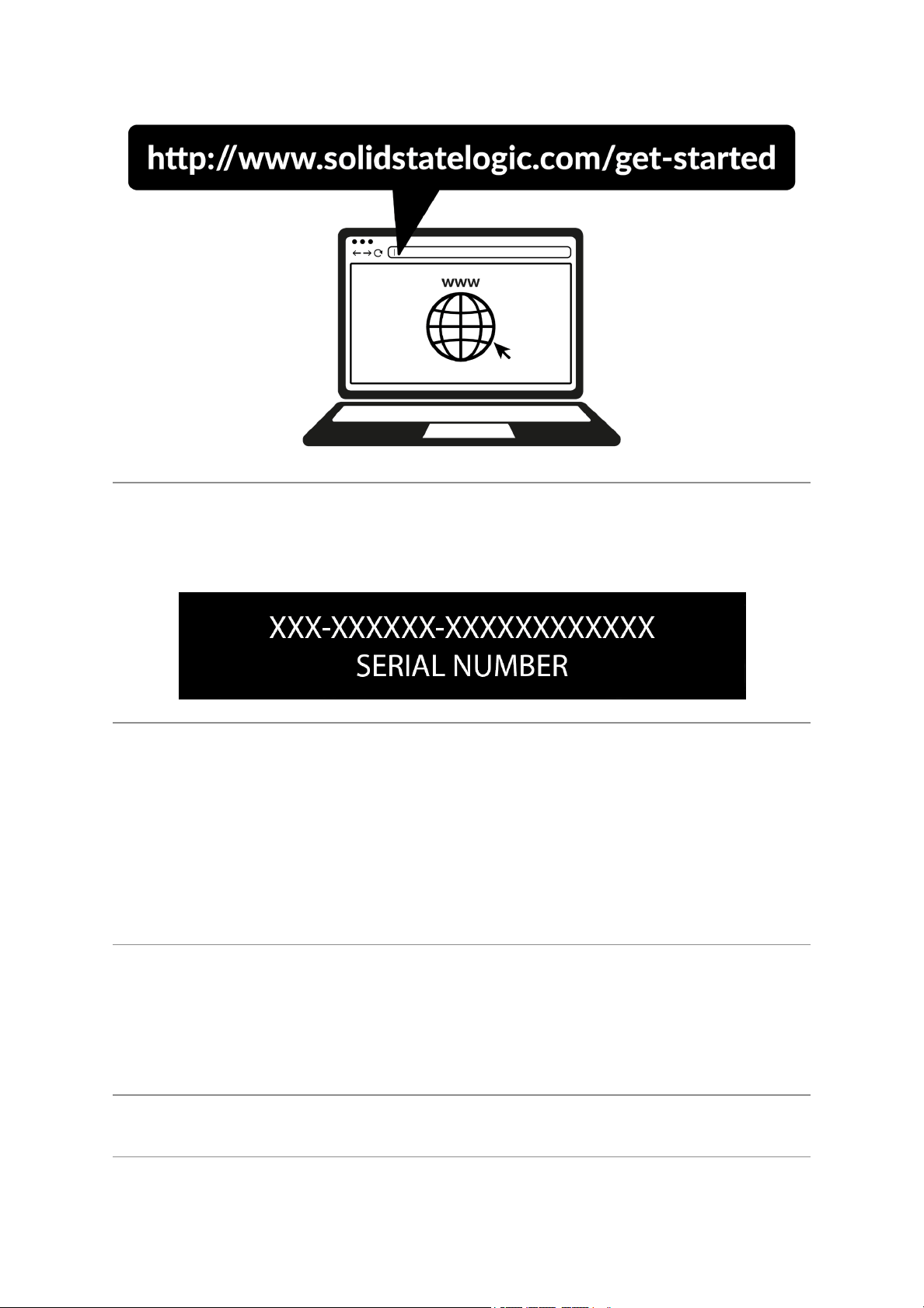
2. (Mac) Simply go to ‘System Preferences’ then ‘Sound’ and select 'SSL 12’ as
the input and output device (drivers are not required for operation on Mac)
Downloading SSL 360° Software
SSL 12 requires the SSL 360° software to be installed on your computer in order to
fully function. SSL 360° is the brain behind your SSL 12 Mixer and controls all
internal routing and monitoring configuration. Once you have connected your SSL12
hardware to your computer as described on the previous page, please download
SSL 360° from the SSL website.
1. Go to www.solidstatelogic.com/support/downloads
2. Select SSL 360°from Products drop-down list
3. Download the SSL 360° software for your Mac or PC
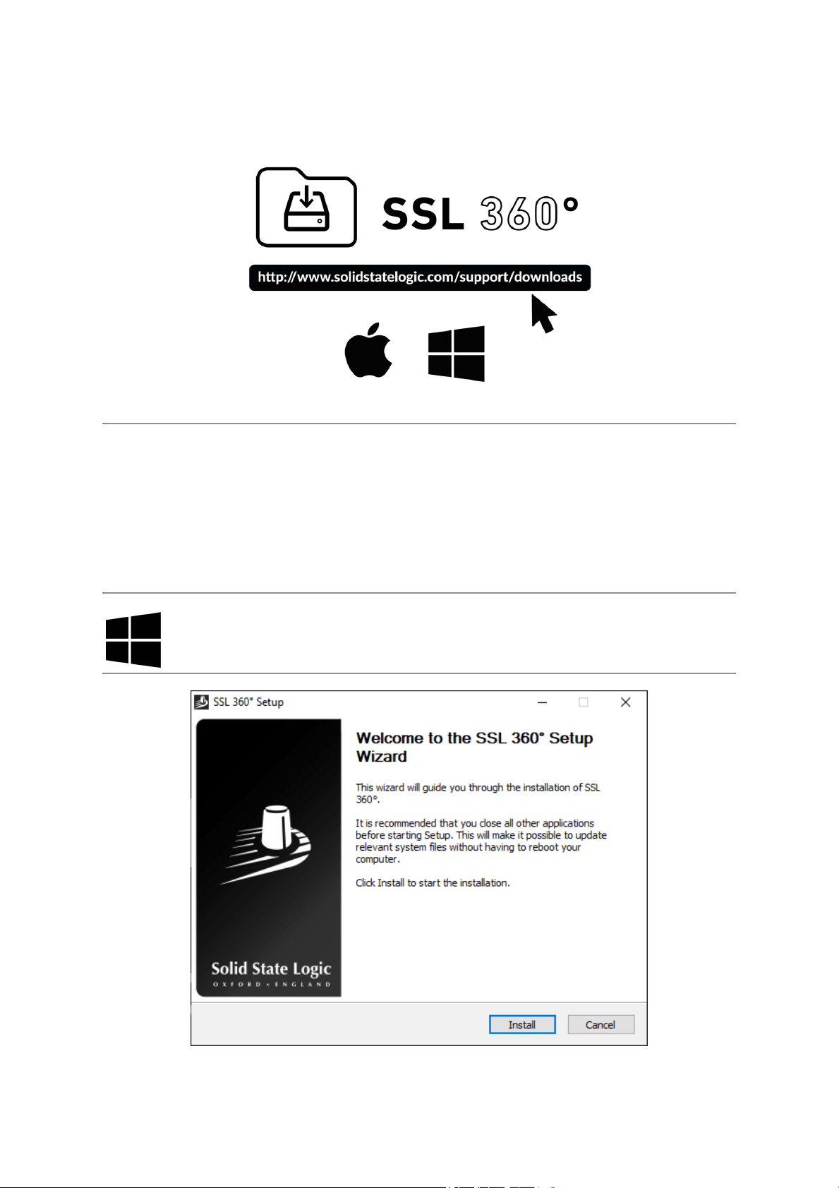
Installing SSL 360° Software
1. Locate the downloaded SSL 360°.exe on your computer.
2. Double-click to run the SSL 360°.exe.
3. Proceed with the installation, following the on-screen instructions.
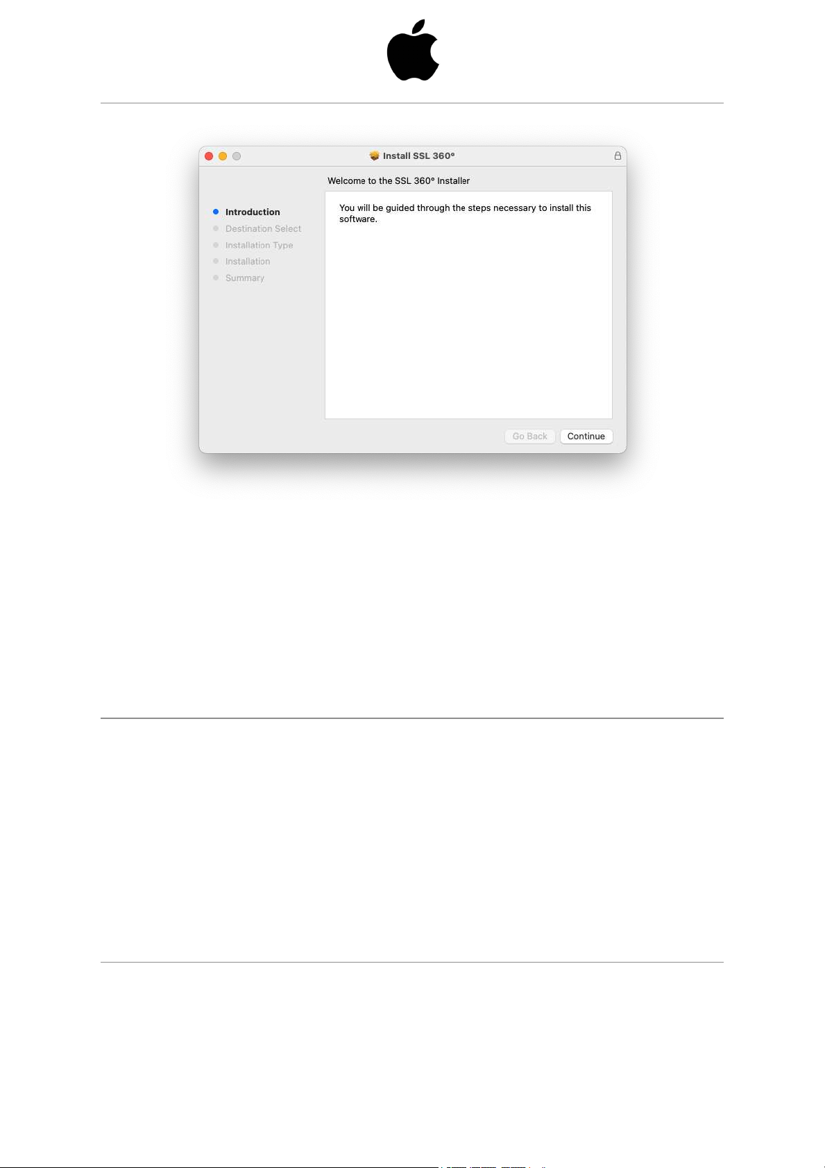
1. Locate the downloaded SSL 360°.dmg on your computer.
2. Double-click to open the .dmg
3. Double-click to run the SSL 360°.pkg
4. Proceed with the installation, following the on-screeninstructions.
Selecting SSL 12 As Your DAW's Audio Device
If you have followed the Quick-Start / Installation section then you are ready to open
up your favourite DAW and start creating. You can of course use any DAW that
supports Core Audio on Mac or ASIO/WDM on Windows.
No matter which DAW you are using, you need to ensure that SSL 12 is selected as
your audio device in the audio preferences/ playback settings. Below is an example
in Pro Tools. If you are unsure, please refer to your DAW's User Guide to see where
these options can be found.
Pro Tools
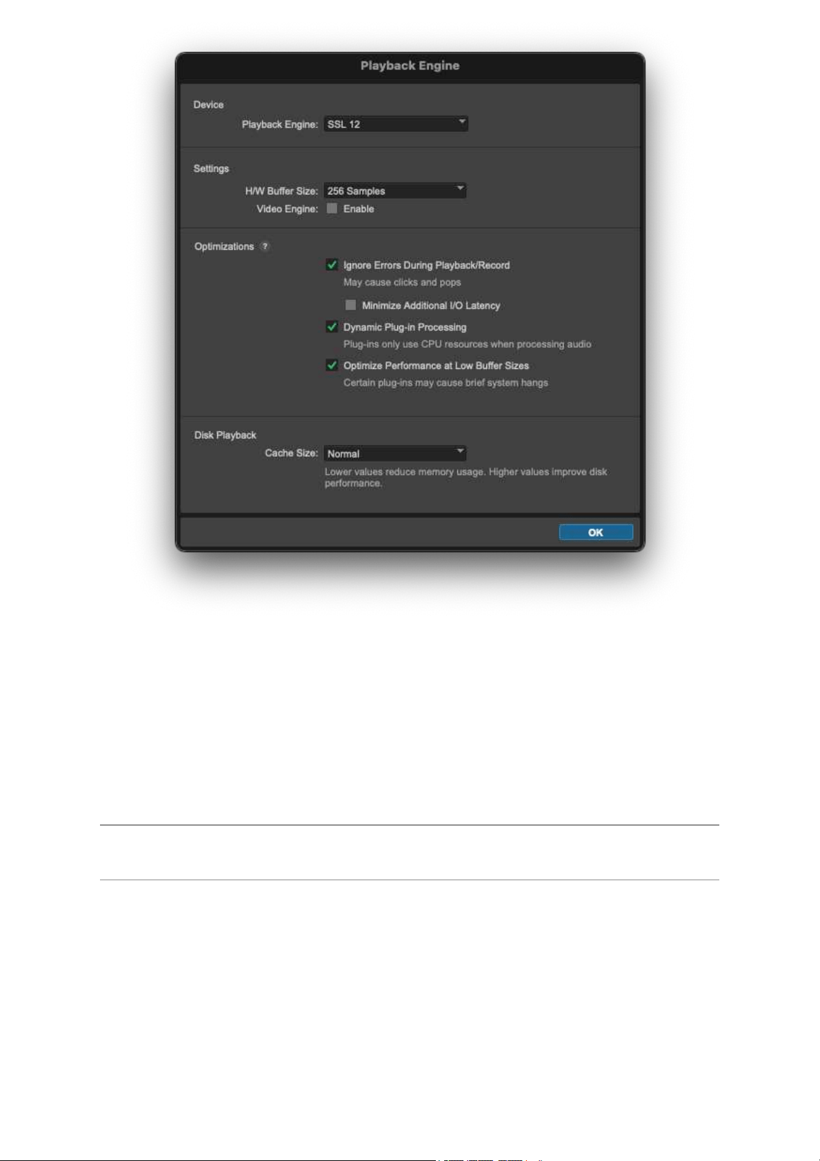
Open up Pro Tools and go to the 'Setup' menu and choose 'Playback Engine...'.
Make sure that SSL 12 is selected as the 'Playback Engine' and that 'Default Output'
is Output 1-2 because these are the outputs that will be connected to your monitors.
Note: On Windows, ensure that 'Playback Engine' is set to 'SSL 12 ASIO' for the
best possible performance.
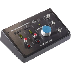
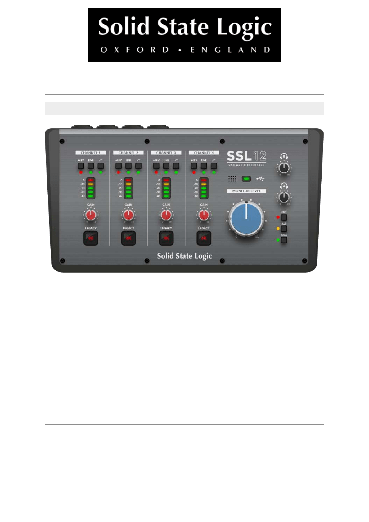
Front Panel Controls
Input Channels
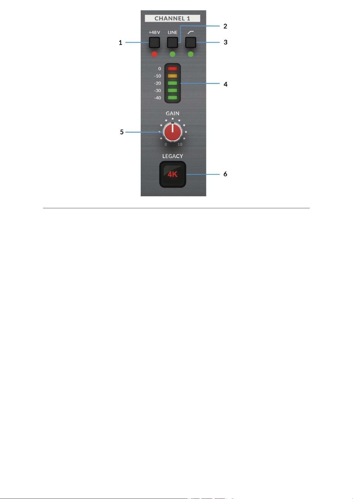
This section describes the controls for Channel 1. The controls for Channels
2-4 are exactly the same.
1. +48V
This switch enables phantom power on the combo XLR connector, which will be
sent down the XLR microphone cable to the microphone. When
engaging/disengaging +48V, the LED blinks a couple of times and the audio is
temporarily muted to avoid any unwanted audio clicks/pops. Phantom power is
required when using Condenser microphones or certain active Ribbon mics.
Dynamic or Passive Ribbon microphones do not require phantom power to operate,
and in some cases can cause damage to the microphone. If in doubt, make sure
+48V is off before plugging in any microphone and consulting the user manual from
the manufacturer to ensure correct operation
2. LINE
This switch changes the source of the channel input to be from the balanced Line
input. Connect line-level sources (such as keyboards and synth modules) using a
TRS Jack cable into an input on the rear panel.
3. HI-PASS FILTER
This switch engages the Hi-Pass Filter with a cut off frequency at 75Hz with a
18dB/Octave slope. This is ideal for removing unwanted low-end frequencies from
an input signal and cleaning up unnecessary rumble. This is suitable for sources
such as Vocals or Guitars.
4. LED METERING
5 LEDs show the level at which your signal is being recorded into the computer. It is
good practice to aim for the '-20' mark (the third green meter point) when recording.
Occasionally going into '-10' is fine. If your signal is hitting '0' (top red LED), that
means it is clipping, so you'll need to lower the GAIN control or output from your
instrument. Scale markings are in dBFS.
5. GAIN
This control adjusts the pre-amp gain applied to your microphone, line-level or
instrument. Adjust this control so that your source is lighting all 3 green LEDs most
of the time whilst you are singing/playing your instrument. This will give you a
healthy recording level into the computer.
6. LEGACY 4K - ANALOGUE ENHANCEMENT EFFECT
Engaging this switch allows you to add some extra analogue 'magic' to your input
when you need it. It injects a combination of high-frequency EQ-boost, together with
some finely tuned harmonic distortion to help enhance sounds. We have found it to
be particularly pleasant on sources such as vocals and acoustic guitar. This
enhancement effect is created completely in the analogue domain and is inspired by
the kind of extra character the legendary SSL 4000-series console (often referred to
as '4K') could add to a recording. The 4K was renowned for many things, including a
distinctive 'forward', yet musical-sounding EQ, as well as its ability to impart a
certain analogue 'mojo'. You will find that most sources become more exciting when
the 4K switch is engaged!
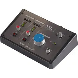
Monitor Controls
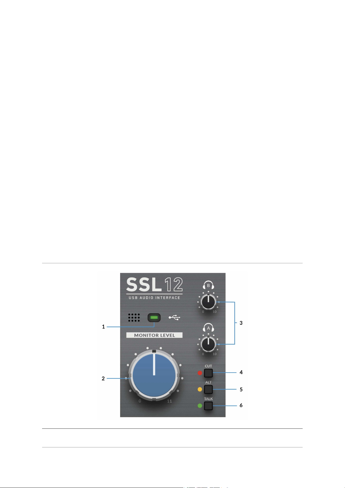
1. GREEN USB LED
Illuminates solid green to indicate that the unit is successfully receiving power over
USB.
2. MONITOR LEVEL (Large Blue Control)
The MONITOR LEVEL directly affects the level sent out of OUTPUTS 1(Left) and
2(Right) to your monitors. Turn the knob to make the volume louder. Please note
the MONITOR LEVEL goes to 11 because it's one louder.
Note that if ALTis engaged, Monitors connected to OUTPUTS 3 & 4 will also
becontrolledvia the Monitor Level Control.
3. PHONES A & B
These controls each set the level for the PHONES A & Bheadphones output.
4. CUT
This button mutes theMonitor Output Signal
5. ALT
Switches the Monitor Bus to an alternative set of monitor speakers that you have
connected to OUTPUTS 3&4. To do this ALT SPK ENABLE must be active in SSL
360°.
6. TALK
This button engages the on-board Talkback mic. The signal can be routed to any
combination of Headphones A, Headphones B and Line 3-4 (providing Line 3-4 is
not being used as ALT monitors) in the SSL 12 Mixer page of SSL 360°. The
Talkback Mic is located to the left of the green USB light.
Please Note: Interface buttons annotated as4, 5 & 6 in the description are also
user-assignable using SSL 360° but they come defaulted to the silkscreened
functions (CUT, ALT, TALK) on the front panel.
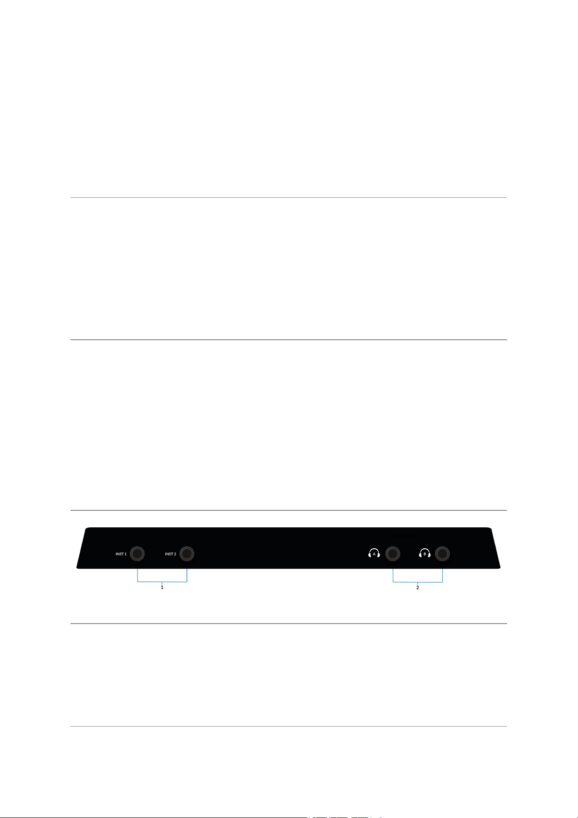
Front Panel Connections
1 . INSTRUMENT INPUTS
INST 1 & INST 2 are the HI-Z Instrument line inputs that allow high impedance
sources such as Guitars & Basses to be recorded without the need for an external
D.I. Plugging into an Instrument input will automatically over-ride the Mic/Line input
on the rear.
2. HEADPHONE OUTPUTS
PHONES A&B allow for two sets of headphones to be connected, both of which
can be configured to allow independent mixes for artist and engineer. The master
output levels are set by the PHONES A and PHONES B controls on the front panel.
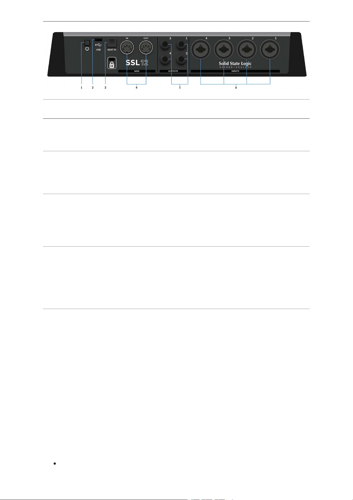
Rear Panel Connections
1 . POWER
The power button toggles power on/off to the unit.
2. USB
USB 'C' Type Connector - connect SSL 12 to your computer using the included
cable.
3. ADAT IN
The ADAT IN - a further 8 input channels to be added to the interface at 48 kHz, 4
channels at 96 kHz, and 2 channels at 192 kHz, allowing expansion to enable larger
recording projects.
4. MIDI IN & OUT
The MIDI (DIN) IN & OUT allow the SSL 12 to be used as a MIDI interface. MIDI IN
will receive MIDI signals from keyboards or controllers & MIDI OUT allows MIDI
information to be sent out to trigger Synths, Drum machines or any MIDI controllable
equipment you have available.
5. OUTPUTS
1/4" TRS Jack Output Sockets
Outputs 1 & 2 are primarily to be used for your main monitors and the physical
volume is controlled by the Monitor Knob on the front of the Interface. Outputs 3 & 4
can be set up as a secondary ALTpair of monitors (switchable to be controlled by
the Monitor Knob when the ALTbutton is engaged).
All Outputs (including headphone outputs as previously described) are also DC-
coupled and able to send +/-5v signal to allow CV control to Semi & Modular
Synths, Eurorack and CV-enabled outboard FX.
Please Note: More information is available in theDC Coupling CV Control via
Ableton® Live CV Toolssection in this User Guide.
A few things to be aware of when using the DC-coupled outputs:
When using output 1-2 for CV output, remember the Monitor Control Knob is
still affecting the signal. Set it fully Clock Wise for full signal.
Meters in the 360° Mixer are DC coupled hence you can still expect them to
work and show a DC signal.
6. INPUTS
Combo XLR / 1/4" Jack Input Sockets
The 4 rear combo jacks accept Mic-level inputs (on XLR) and Line-level inputs (on
TRS). Hi-Z inputs for Channels 1 & 2 are located at the lower front of the interface
and plugging into these will over-ride any Mic/Line rear panel inputs.
SSL 360°
Overview & Home Page
SSL 12 is configured via the SSL 12 page in SSL 360°. SSL 360° is a cross-platform
Mac and Windows application that also manages other SSL 360°- enabled
products.
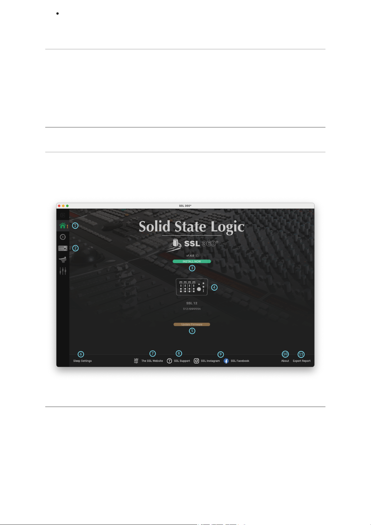
The Home Screen
1. Menu Toolbar
This toolbar allows you to navigate through the various pages of SSL 360°.
2. SSL 12 Mixer
This tab opens the SSL 12 Interface Mixer; allowing for Routing, Input channel &
Playback management, Monitor controls & settings for the SSL 12 interface within
your system. More information on the SSL 12 360° Mixer is detailed in the next
chapter.

3. Software Version Number & Update Software Button
This area displays the version number of SSL 360° that is running on your computer.
When software updates become available, the Update Software button (pictured
above) will appear. Click this to download and update your software. Clicking on the
'i' symbol will take you to the Release Notes information on the SSL website for the
version of SSL 360° you have installed
4. Connected Units
This area shows if you have SSL 360° hardware (SSL 12, UF8, UC1) connected to
your computer, along with its serial number. Please allow 10-15 seconds for units to
be discovered once they are plugged in.
5. Firmware Updates Area
If a firmware update becomes available for your SSL 12 unit, then an Update
Firmware button will appear below each unit. Click on the button to start the
firmware update process, being sure to not disconnect the power or USB cable
whilst it is in progress.
6. Sleep Settings (applies only to UF8 and UC1, not SSL 12)
Clicking this will open a pop-up window that allows you to determine the length of
time before your connected 360° control surfaces go into Sleep mode.
7. SSL Website
Clicking this link will take you directly to the Solid State Logic website.
8. SSL Support
Clicking this link will take you directly to the Solid State LogicSupport website.
9. SSL Socials
The bar at the bottom has quick links to the SSL Socials to keep up to date on the
latest news, product tutorials & updates on SSL users.
10. About
Clicking this will open a pop-up window detailing software licensing relating to SSL
360°
11. Export Report
Should you encounter any issues with your SSL 12 or SSL 360° software, you may
be asked by a support agent to use the EXPORT REPORT feature. This feature
generates a text file containing the essential information about your computer
system and SSL 12, alongside technical log files relating to SSL 360° activity, which
may help to diagnose any issues. When you click EXPORT REPORT, you'll be
asked to choose a destination on your computer to export the generated .zip file to,
which you can then forward onto a support agent.
SSL 12 Mixer Page
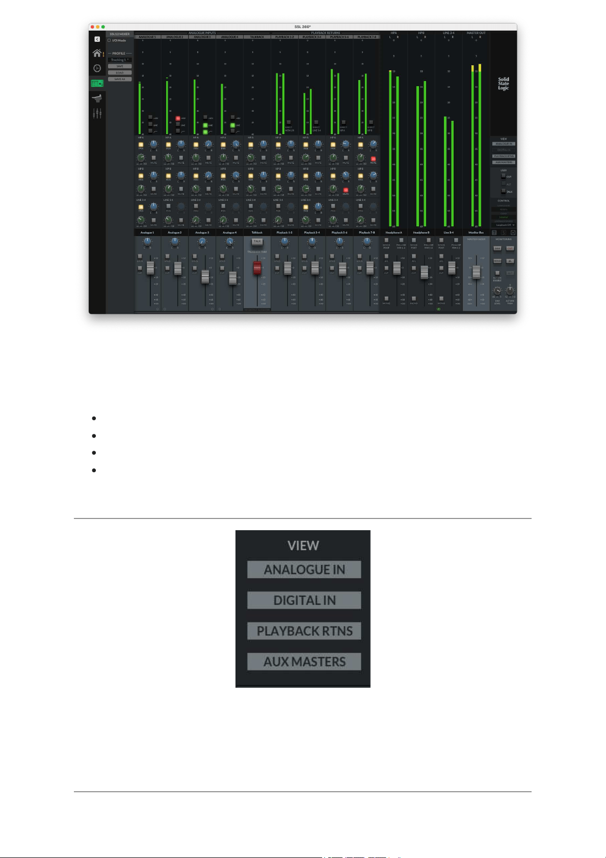
In order to access the powerful routing and input channels from ADAT & your DAW,
the 360° Mixer presents you with a console-style layout with all controls available in
a detailed but intuitive workspace. In this page you can:
Easily set up multiple headphone mixes
Configure your control room monitor mix
Choose your Loopback source
Change the 3 user-assignable front panel buttons
VIEW
Within the mixer, use the VIEW buttons on the right-hand side to hide/show different
input channel types (Analogue Inputs, Digital Inputs, Playback Returns) and the Aux
Masters.
Inputs - Analogue & Digital
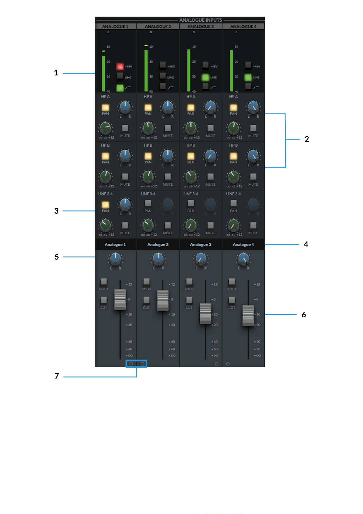
1. Meters
The meters indicate the incoming signal level to the channel. If the meter turns red
then it demonstrates the the channel has clipped. Click on the meter to clear the clip
indication.
The +48V, LINE & HI-PASS functions can be controlled from either the hardware or
SSL 12 software mixer.
2. Headphone Sends

This is where you can create independent mixes for HP A, HP B and Line 3-4
Outputs.
The Green Knob controls the set level for each Mix Bus (HP A, HP B &
Outputs 3-4)
MUTE button mutes the send and illuminates red when activated.
The Pan control allows you to determine the pan position for that send. The
PANbutton must first be engaged.
IfPAN is not engaged, then the send follows the main monitor bus Pan
control in the fader section.
Tips:
Shift + Mouse Click sets a send to 0 dB.
Alt + Mouse Click (Mac) or Option+Click (Windows) sets a send to Off.
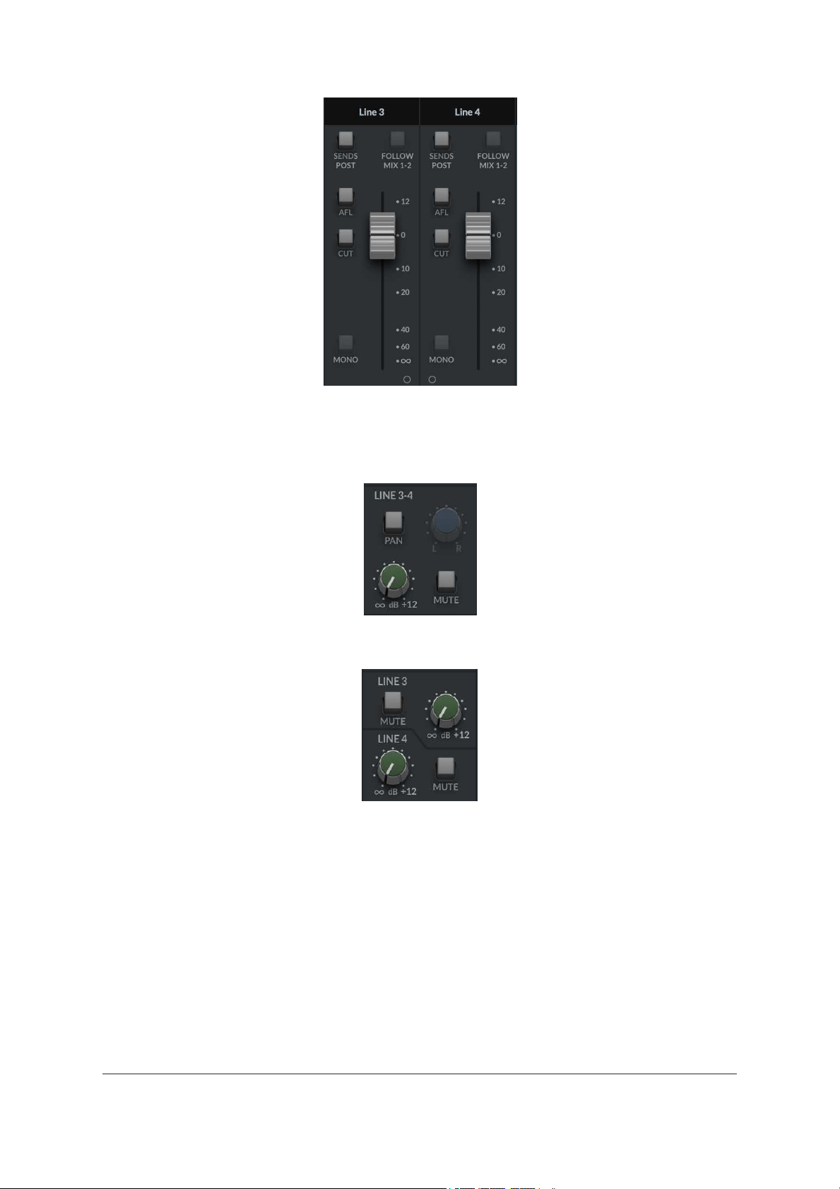
3. Line 3-4 Sends
Similar to the headphone sends, the Line 3-4 sends allow the signal to be routed to
Outputs 3-4. When the output channel is stereo linked, a single set of controls for
Pan, Level and Mute are controllable.
When the output channel is split into dual-mono, independent level controls appear,
one for Output 3 and one for Output 4.
4. Scribble Strips
These are the text boxes on each channel identifying its input/output type and
number order as default. These text boxes are editable, allowing each channel in
the 360° mixer to be renamed by the user.
To re-name the Scribble Strip on the channel, simply double-click on the text box
and type your preferred name.
5. Pan
The Pan control determines the position of the signal in the Monitor Bus stereo
image.
6. Faders
The Fader section of the mixer allows control of the signal going out to the Monitor
Bus & consists of 4 control parameters.
Pan Knob as previously described.
Solo button, soloing the channel in the Monitor Bus. This illuminates yellow
when activated.
Cut button mutes the channel to the Monitor Bus. This illuminates red when
activated.
Fader control the level, with a range from +12dB to -Infinite dB being sent to
the Monitor Bus.
Tip:
Shift + Mouse Click sets the fader to 0 dB. Alt + Mouse Click also sets the fader to 0
dB.
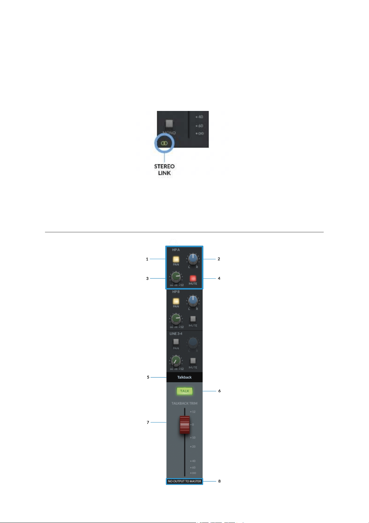
7. Stereo Link
Clicking on either 'O', two sequential channels can be stereo linked and will convert
to a single fader stereo channel. When activated this 'O' will change to a green
linkedsymbol as shown below:
Note: These controls affect only the playback of the signal via the Monitor Bus, and
won't affect the signals recorded into your DAW.
Talkback
Routing Sections HP A Highlighted as an example

In the same way as the Input channels, the TALKBACK channel can be routed to the
Headphones & Line Output 3&4.
1. The PAN button when illuminated engages the send's Pan.
2. Pan Knob allows you to determine the pan position for that mix being sent to
the Aux Bus.
3. The Green Knob controls the set level for each Aux Bus (HP A, HP B &
Outputs 3-4) from +12dB to -Inf dB.
4. MUTE button mutes the send and illuminates red when activated.
This layout is identical for Headphones B & Line Out 3-4
5. Scribble Strip
This text box identifies the TALKBACK channel and is named as default. This text
box is also editable, allowing it to be renamed by the user.
6. TALKBACK ENGAGE BUTTON
When illuminated green, the built-in TALKBACK mic will send the signal to the
routed aux buss(es) (HP A, HP B & LINE 3-4). This can also be controlled by
physically engaging the TALKBACK button on the SSL 12 Interface, or via the SSL
360° TALK software button (if assigned).
7. FADER
The red capped fader sets the master output level of the TALKBACK signal. The
Fader ranges from +12dB & -Inf dB.
8. NO OUTPUT TO MASTER
The text at the bottom of the TALKBACK channel is a reminder that the TALKBACK
signal is not sent to the MONITOR BUS& can only be routed via the aux sends.
Digital Inputs
The 8 channels of Digital Inputs are provided by the optical ADAT IN port at the rear
of the interface, accepting 8 channels at 44.1/48 kHz, 4 Channels at 88.2/96 kHz
and 2 channels at 176.4/192 kHz.
The Digital Inputs provide no gain controls. Gains should be set on the external
ADAT device.
Routing to the HP A, HP B & LINE 3-4 is identical to the Analogue Input Channels.
Playback Returns
The 4x Stereo Playback Return channels allow separate stereo signals to be sent
out of your DAW or other programs with assignable audio outputs, into the SSL 12
Mixer as inputs.
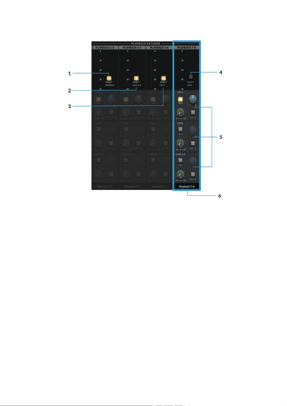
At the top of the channel next to the meters, the 'Direct' button allows each stereo
Playback Return to bypass the SSL 12 Mixer's Routing Matrix and instead the signal
is sent directly to the corresponding Aux/Bus Master.
In the above diagram, Playback 7-8 is highlighted in Blue to distinguish the
difference between engaged & disengaged Direct Buttons.
1. DIRECT MON L-R
Engaging the DIRECT button will send the DAW Mon L/R outputs directly to the
main Monitor Bus (OUT 1-2), bypassing the Routing Matrix.
2. DIRECT LINE 3-4
Engaging the DIRECT button will send the DAW 3-4 outputs directly to Line 3-4 Aux
Master (OUT 3-4), bypassing the Routing Matrix.
3. DIRECT HP A
Engaging the DIRECT button will send the DAW 5-6 outputs directly to Headphone
A Aux Master (OUT 5-6), bypassing the Routing Matrix.
4. DIRECT HP B
On Playback 7-8, engaging the DIRECT button will send the DAW 7-8 outputs
directly to Headphone B Aux Master (OUT 7-8), bypassing the Routing Matrix.
5. ROUTING MATRIX
When the DIRECT Button is disengaged, the signals can be routed to the HP A, HP
B & Line 3-4 from the SSL Mixer. As with the Input Channels, sends to the aux
busses are controlled via the HP A,HP B & LINE 3-4 Send Level Knobs, with Pan,
and muting button also accessible.
6. SCRIBBLE STRIP
This text box identifies the Playback Return Channel and is named as displayed by
default. The text box is editable, allowing it to be renamed by the user.
FADER
The fader controls the level sent to the Monitor Bus for each Playback Return
Channel (providing DIRECT is disengaged), as well as providing SOLO,CUT &
PANfunctionality.
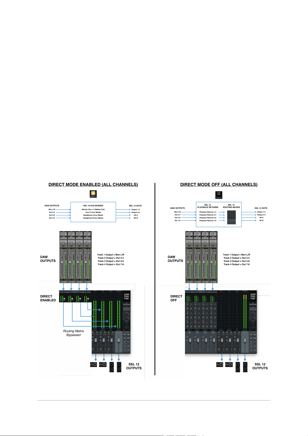
Below is a visual illustration of DIRECT MODE. For simplicity, the illustration shows
all Playback Returns with DIRECT Enabled (left-hand side) and all Playback
Returns with DIRECT Disabled (right-hand side). Of course, you have the ability to
toggle the DIRECT mode on/off for each Stereo Playback Return Channel.
AUX Masters
The Aux Masters section of the Mixer View consists of both Headphones A,
Headphones B & Line Out 3&4 aux master outputs.
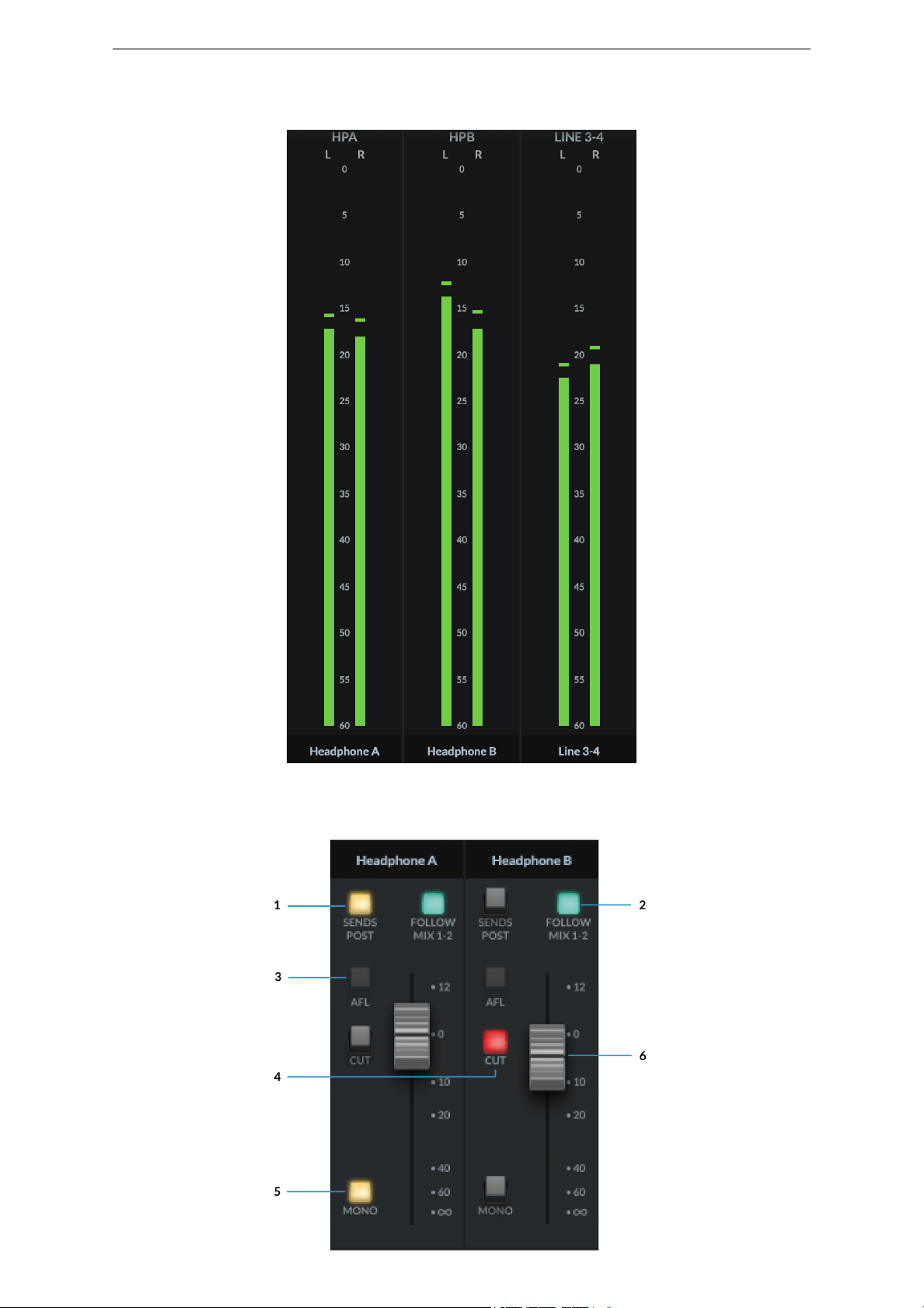
Headphone Outputs
Each Headphone Output consists of a large Signal Metering section with a
resolution from 0dB down to -60dB.
Below are details of the Fader section with the following parameters:
1. SENDS POST
When selected, send levels to the aux busses from the channels will be Post Fader
level.
2. FOLLOW MIX 1-2
Over-rides the aux master so that it follows the Monitor Bus mix, providing an easy
way to send what you are listening to on the Monitor Bus (through your monitor
speakers) to the Headphones.
3. AFL
Short for'After Fade Listen' allows the user to monitor the Aux Mix on the Main
Outputs; ideal for quickly listening to the Artist's headphone mix.
4. CUT
Mutes the signal output of the HP Aux channel
5. MONO
Switches the output to Mono, summing both L&R signals together.
6. Fader
Sets the master level for the HP Bus. Remember this is pre physical gain control on
the SSL 12 front panel.
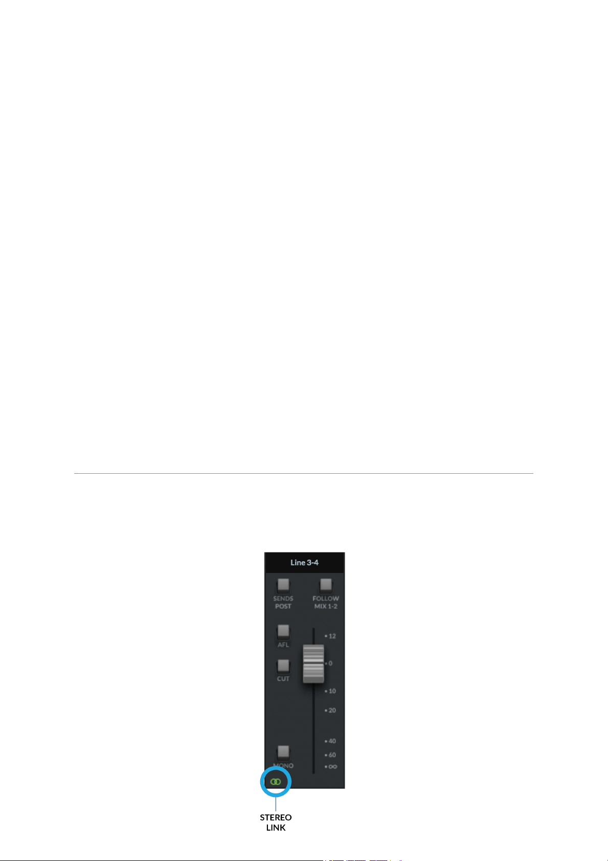
Line Output 3-4 Master
The Line 3&4 aux master has all the same parameter controls as the Headphones
aux masters, but with the addition of the Channel linking button at the very bottom of
the fader section.
When linked, the button glows green and represents Stereo Operation
Unlinked
. When unlinked, this will configure Line 3 &4 as independent mono busses.
Left: Sends when Line 3-4 is linked , Right: Sends when Line 3-4 are unlinked.
When unlinked all input channels in the SSL 12 mixer will change their Line 3&4
sends to individual levels & mutes. If already set as a send to 3&4, the levels
already set will be maintained in Mono between each channel.
Within the SSL 12 360° Mixer, the signal sent to each Headphone Mix can be
derived from any Input Channel or Playback Return or can mirror the main output
mix by implementing the 'Follow Mix 1-2' button on the HP Channel in the Mixer.
MASTER OUT
This is the MONITOR BUS feeding your monitors via OUTPUTS 1-2 (or ALT
OUTPUTS 3-4).
The MASTER FADER level will control the output volume signal, pre the physical
Monitor Level Control on the SSL 12 Interface.
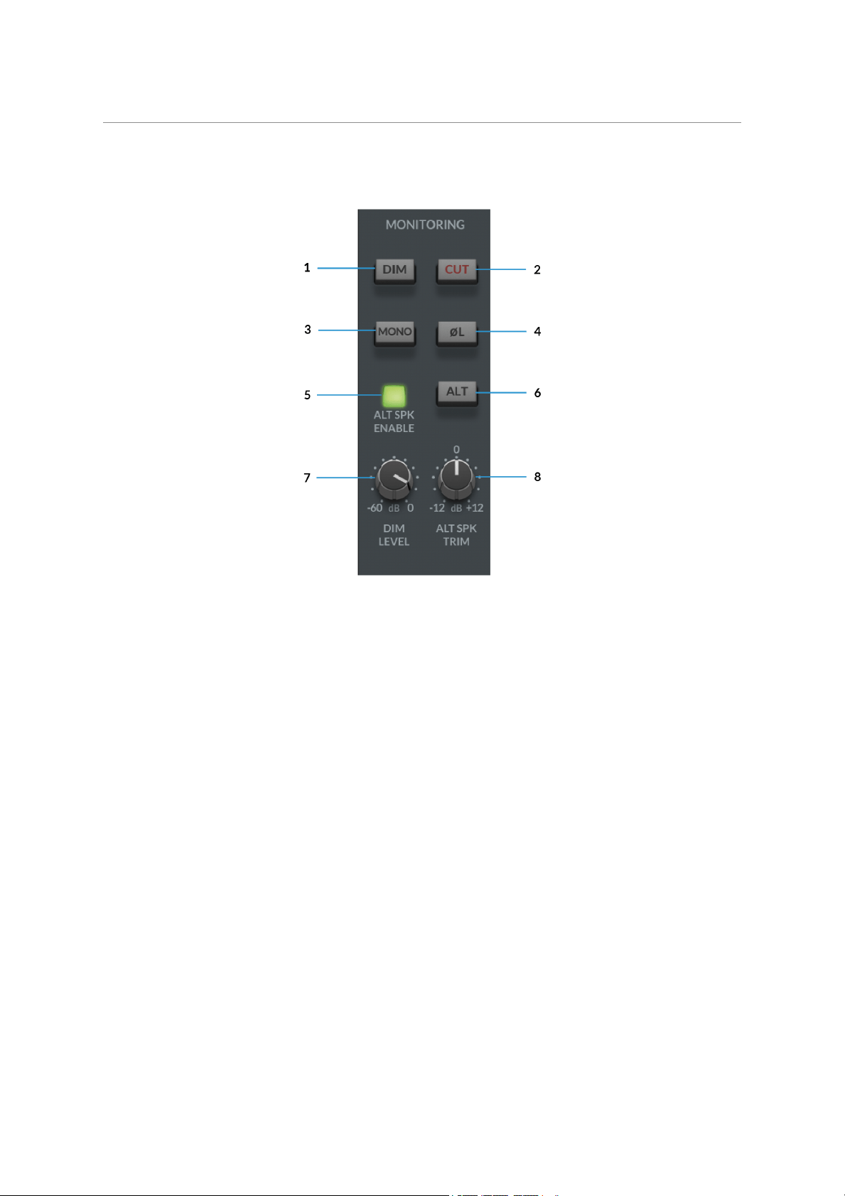
MONITORING
This section of the Mixer pertains to the control of your SSL 12's range of
comprehensive monitoring features.
1. DIM
The DIM button will engage a level attenuation set by the DIM LEVEL (7)
2. CUT
Cuts the output to the monitors.
3. MONO
This will sum the Left & Right channel signals of the Master Out together and
provide a MONO output signal to the Main Outputs.
4. POLARITY INVERT
This will invert the left side signal, allowing assessment of the phase relationship
between the left & right signal.
5. ALT SPEAKER ENABLE
This function allows you to connect a second set of monitors to Line Outputs 3-4.
When ALT SPK is enabled, the MONITOR LEVEL will also affect the output signal
level to Outputs 3&4 when ALT is engaged.
6. ALT
With ALT SPK ENABLE (5) engaged, engaging the ALT button will transfer the
MASTER BUSsignal to Outputs 3&4.
7. DIM LEVEL
The DIM LEVELcontrol adjusts the level of attenuation provided when the DIM (1)
button is engaged. This allows up to -60dB of attenuation when fully tuned counter-
clockwise.
8. ALT SPEAKER TRIM
The ALT SPKR TRIM knob allows gain adjustment to offset the output level sent to
the ALT monitors connected to Outputs 3&4. This allows the levels to be adjusted
between the Main Monitors and Alt Monitors so the Monitor Controllevel doesn't
need to be changed when A/Bing between two different sets of speakers for a more
accurate comparison.
SETTINGS
In the bottom-right of the SSL 12 Mixer, you can access the Settings panel, which
contains configuration options for the Headphone outputs and also Peak metering.
HEADPHONE OUTPUTS MODES
The HP outputs can operate in one of 2 modes:
Headphones Mode
Line Output Mode
Headphones Mode Options
When operating in Headphones Mode, you can choose between 3 different options:
Standard- The default setting and is suitable for a wide range of headphones.
High Sensitivity - This is most applicable for use with certain In-Ear Monitors
(IEMs) or headphones that have especially high sensitivity (expressed in
dB/mW). Typically, headphones that specify their performance at 100 dB/mW
or higher.
High Impedance - This setting is ideal for High Impedance headphones which
require greater voltage drive to produce the expected output level. Typically,
headphones with an impedance of 250 Ohms or greater will benefit from this
setting.

Beware: Always make sure BEFOREyou switch your headphone output to High
Impedance, to turn the front panel level control down to avoid accidentally
overloading your headphones if you are unsure of what sensitivity they are.
Line Output Mode Options
HP A and HP B can be switched into Line Output Mode. This allows you to use them
as additional mono line outputs, instead of headphone outputs.
By default they are balanced but you can make them unbalanced by click the
Unbalanced box.
Please beware when switching the output setting between Balanced & Unbalanced
to be aware of the cables being used and the destination of the signal as not to
introduce noise or distortion into the circuit.
METERS PEAK HOLD
Determines how long the peak hold segment of the SSL meters hold for.
No Peak Hold
Hold for 3 Seconds
Hold Until Cleared
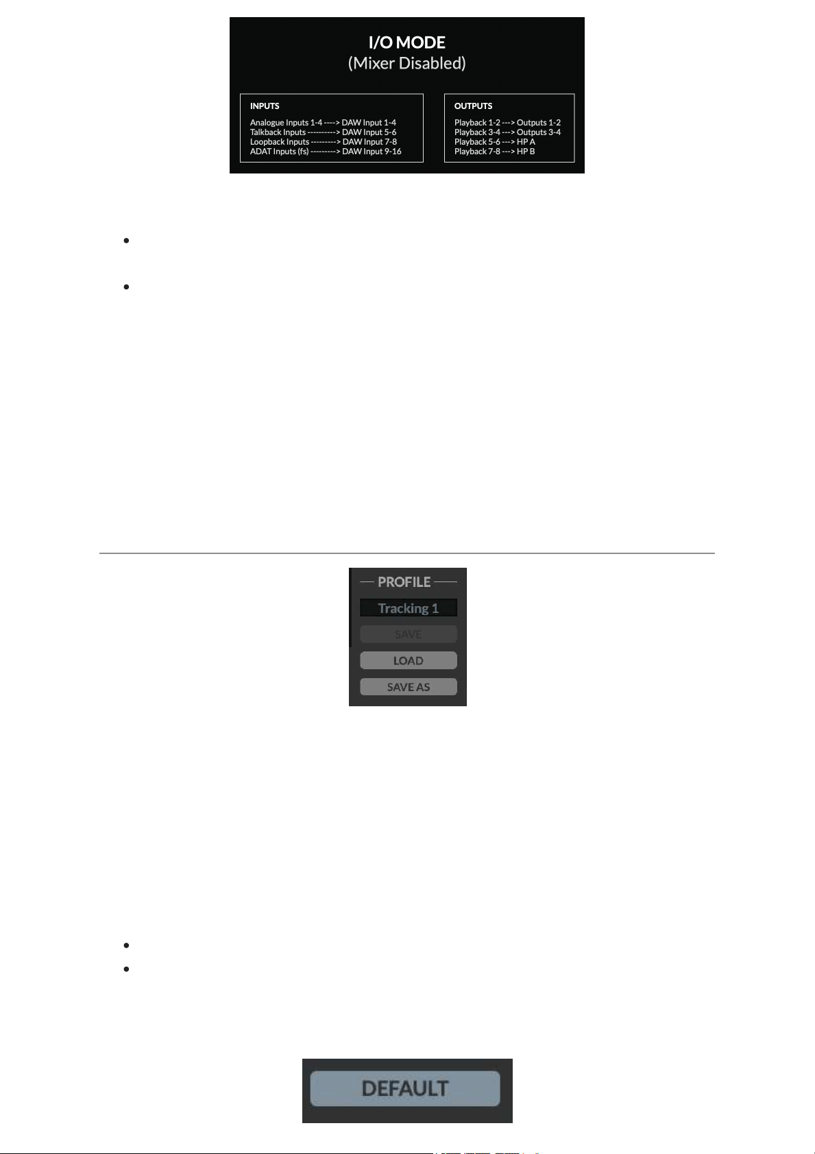
I/O MODE
You can put SSL 12 into I/O Mode by engaging the tickbox in the upper-left corner
of the SSL 12 Mixer.
I/O Mode bypasses the SSL 12 Mixer's routing matrix and fixes the routing as
shown in the table below:
I/O Mode can be used for different purposes:
To simplify the operation of the unit when you do not need the full flexibility that
the SSL 12 Mixer offers.
It allows SSL 12's outputs to operate at 176.4 or 192 kHz, instead of
downsampling them.
When I/O Mode is not engaged (SSL 12 Mixer is active) and you are
operating at sample rates of 176.4 or 192 kHz, SSL 12's outputs are
automatically downsampled to 88.2 or 96 kHz in order to preserve the full
mixing capability of the mixer. Other audio interfaces typically limit mixer
capability in the same scenario.
So if you want end-to-end 176.4 or 192 kHz performance, then I/O Mode is a useful
option.
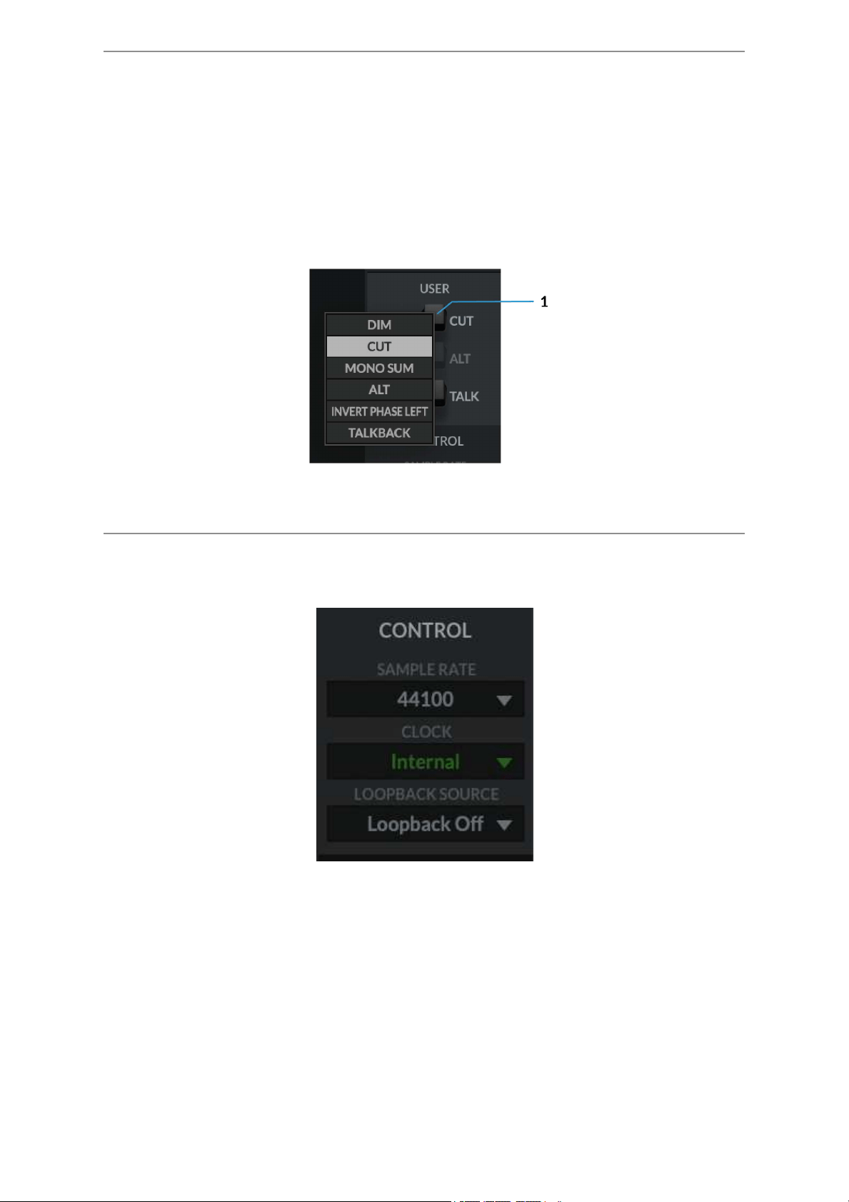
PROFILE
The user can Save and Load customised profiles for the SSL 12 Mixer. To Save a
Profile, simply press SAVE AS and name your new Profile, which will be saved in
the SSL 12 folder for easy recall.
To load an existing profile, press the LOAD button, which will then open a window to
all the saved profiles, and can be selected by pressing 'Open'.
The default storage location for both Mac & Windows OS's is shown below, although
they can be saved & stored from any location.
Mac – Mac HD\Users\%userprofile%\Documents\SSL\SSL360\SSL12
Windows – %userprofile% \Documents\SSL\SSL360\SSL12
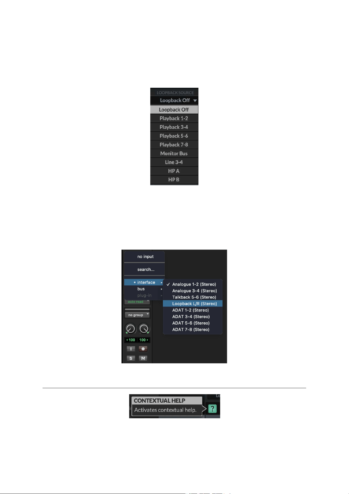
Click the DEFAULT button, to return the SSL 12 Mixer to its factory-shipped, default
state.
USER Buttons
By Default, the User buttons are assigned to match the printing on the SSL 12
Interface front panel - CUT, ALT & TALK.
A right-mouse click presents a menu whereby you can change the assignment of
these buttons. You can choose between DIM, CUT, MONO SUM, ALT, INVERT
PHASE LEFT, TALKBACK ON/OFF.
CONTROL
The Control section displays key information in setting up your Interface ready for
working within your DAW.
1. SAMPLE RATE
The drop-down menu allows the user to select the Sample Rate that the SSL 12
Interface will operate at. The selection allows for 44.1 kHz, 48 kHz, 88.2 kHz, 96
kHz, 176.4 kHz & 192 kHz. Note, that when any DAW is opened, SSL 12 will follow
the DAW's sample rate setting.
2. CLOCK
The Clock source menu allows the change between INTERNAL clocking or ADAT.
When using an external ADAT unit connected to the SSL 12, select the source to
ADAT, allowing the ADAT-connected device to act as the clocking source (set the
ADAT device to Internal).
3. LOOPBACK SOURCE
This option allows you to record USB audio back into your DAW. This is especially
useful for recording audio from other applications such as Youtube.
To set this up, simply select the LOOPBACK SOURCE channel you wish to record
from the drop-down menu (for example Playback 1-2 to record the output of a media
player), then in your DAW, select the input channel as Loopback as shown below
and record the audio as you would with any other input channel. Be sure to mute the
recording channel in your DAW to avoid creating a feedback loop!
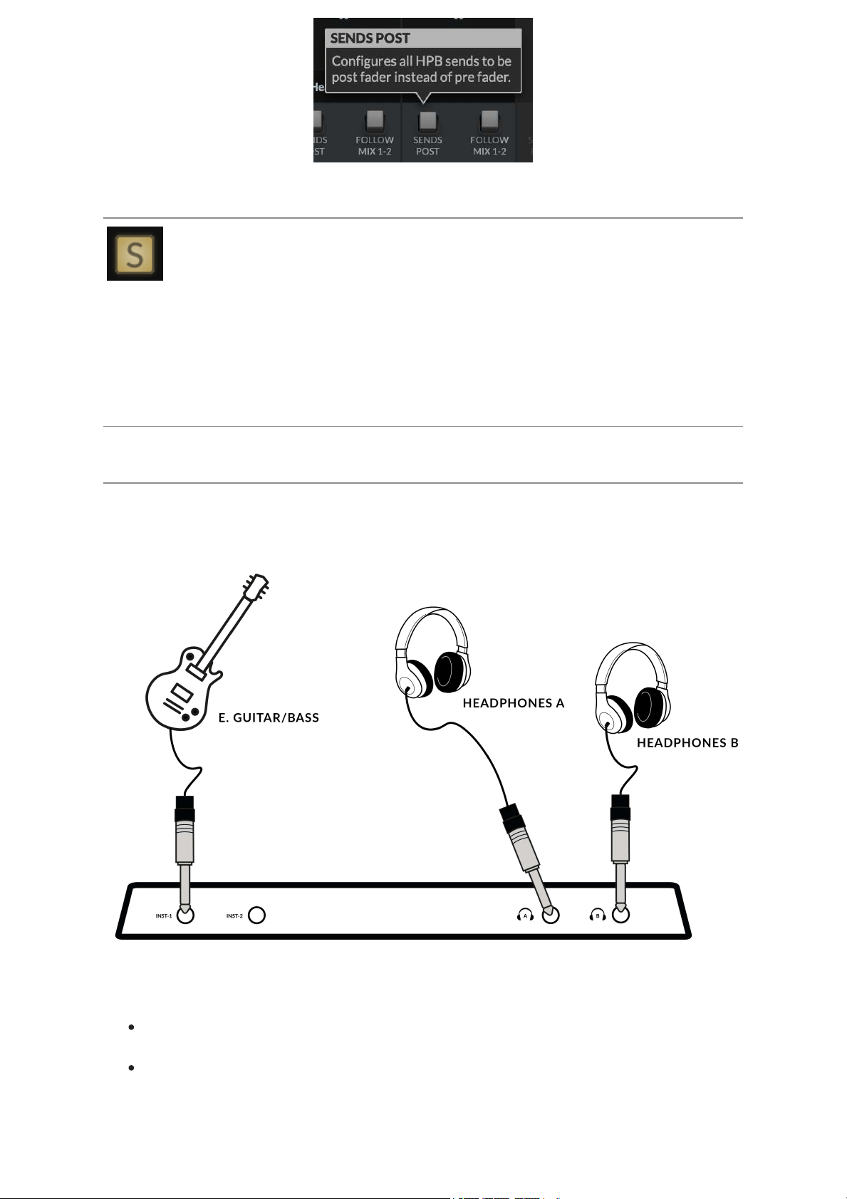
Contextual Help
The Contextual Help, once activated by clicking the ? button (as shown above) adds
a text bar to the tooltip with a brief explanation of the parameter's function. The
below image demonstrates this with an explanation text box when hovering the
mouse over the SENDS POST on the HP B Channel.
Solo Clear
The Solo Clear button allows you to quickly clear any active solo's (or AFLs) in the
SSL 12 Mixer. When any channels have been put into SOLO or AFL, the Solo Clear
button will illuminate yellow.
How-To / Application Examples
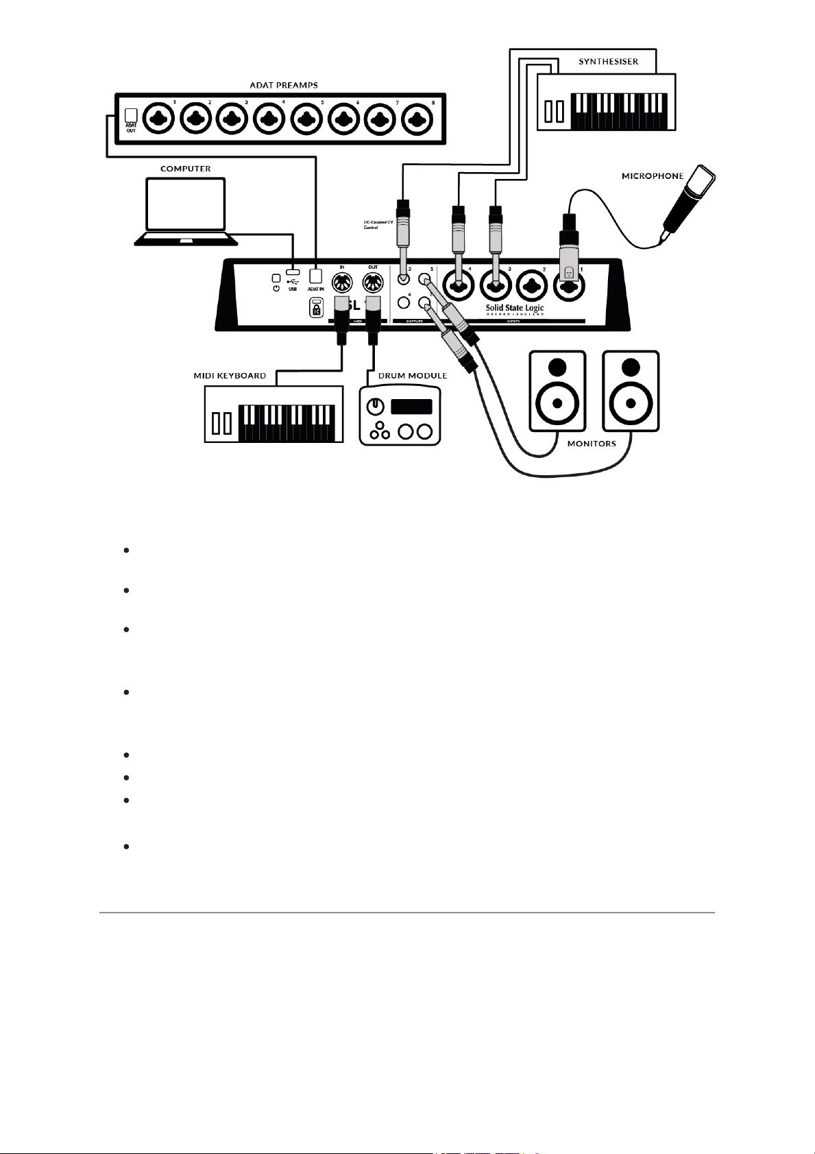
Connections Overview
The diagram below illustrates where the various elements of your studio connect to
SSL 12 on the front panel.
This diagram shows the following:
An E Guitar/Bass plugged into INST 1, using a TS Jack Instrument cable.
Two pairs of Headphones each connecting directly to theHeadphone Outputs
HP A & HP B
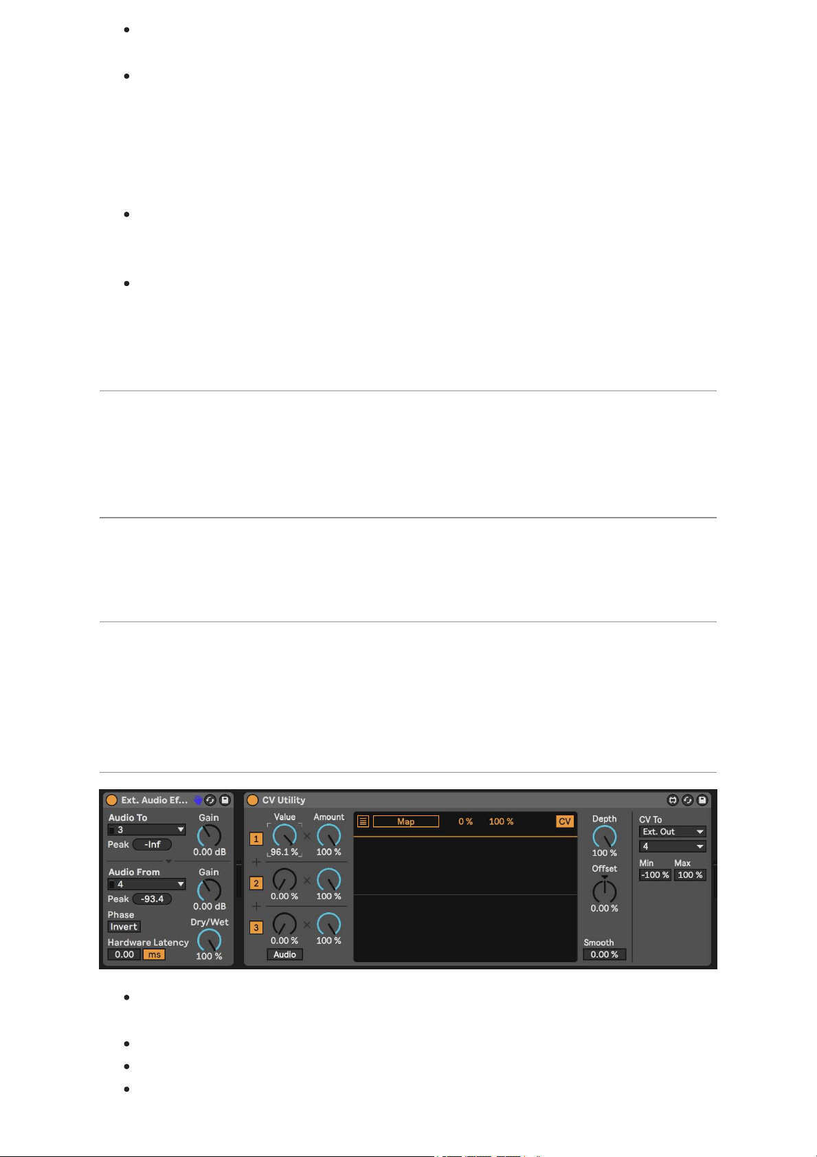
The below example visually details some likely uses for all the potential connections
available on the rear panel of the SSL 12 Interface.
This diagram shows the following:
A microphone plugged into INPUT 1, using an XLR cable
A StereoSynthesiserplugged into INPUT 3&4, using jack cables
Monitor speakers plugged into OUTPUT 1(Left) and OUTPUT 2(Right), using
TRS jack cables (balanced cables)
A TS cable sending DC (+/-5V) out of OUTPUT 3 signal to the Synthesiser to
control CV parameters.
MIDI OUT to trigger a Drum Machine
MIDI IN from a MIDI Control Keyboard
ADAT INfrom an ADAT-enabled Preamp rack feeding 8x Channels of INPUT
signal to the DIGITAL IN Channels of the SSL 12 360° Mixer
USB cable connecting SSL 12 to the computer
DC Coupling CV Control via Ableton® Live CV Tools
All Outputs on the SSL 12 areDC-coupled (1, 2, 3, 4 and Headphone A and
Headphone B when set to Line Output Mode) and able to send +/-5v signal to allow
CV control to Semi & Modular Synths, Eurorack and CV-enabled outboard FX. This
allows the Headphone outputs to be used to send Control Voltage from the front
output pairs.
When using DC-coupled outputs there are a few things to keep in mind:
It's recommended to put SSL 12 into I/O Modeto stop previously routed
signals from accidentally passing to your Main Monitors or Headphones.
When using Outputs 5-6 and 7-8 for DC Control, be careful to first unplug any
attached headphones from the front panel outputs & then switch the outputs to
Line Output Mode using the SSL 12 Mixer page in 360°. SomeHeadphones
might not be happy about receiving excessive DC, so disengage DC outputs
before reattaching headphones to the front panel outputs. For further details
on this please see the SSL 360° section of this manual.
Remember Headphone volume knobs are still affecting the signal, so to
accurately send out correct CV values, set the HP volume knob fully clockwise
for full signal.
Further information on using DC-Coupled Outputs can be read later in this
manual under the
DC Coupling CV Control via Ableton® Live CV Toolschapter.
SSL 12 DC-Coupling Outputs
The SSL 12 Interface allows the user to send out a DCSignalfrom any output on
the interface. Thisallows CV-enabledequipment toreceivethe signal to control
parameters.
What is CV?
CV is an abbreviation of "Control Voltage"; an analogue method of controlling
synthesizers, drum machines and other similar equipment.
What are CV Tools?
CV Tools is a free pack of CV-enabled instruments, synchronisation tools, and
modulation utilities that enable users to seamlessly integrate Ableton Live with
various devices in the Eurorack format or Modular Synthesisers & Analog effects
units.
Setting Up Ableton Live CV Tools
Before Setting up Ableton, first put your SSL 12 intoI/O MODEto ensure no
DCsignal is being sent to your headphones or Main Monitors accidentally.
Open yourAbleton Live session
First set up a new Audio Track that you'll use to send out the CV Signal.
Then insert onto the Audio track a CV Utilities Plug-Infrom the packs menu.
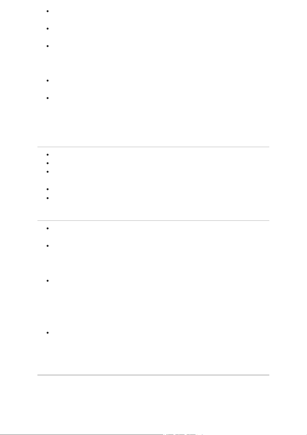
Once the CV Utility Plug-In is Open, set the CV Toto your designated Output.
In this example we've set this to Output 4from the SSL 12.
Set up a second Audio track with the input signal from the Effect/Instrument
and record arm to monitor the input back into Ableton Live.
Now using the CV Value knob on the CV Control channel, you can automate
the CV signal sent out of Ableton to your External Instrument/FX unit. This can
then be mapped to a MIDI controller to control in realtime, or record the
Automation into your session.
Now you can record the audio back into your Ableton Session, or other DAW
you may be using to record your Audio back onto your system.
Please note that multiple CV Utility plugs can be set up when using the SSL 12
as EVERY PHYSICAL OUTPUT is able to send DC signal for CV Control.
Therefore you can use up to 8 CV control signals at any one time using CV
Tools and an SSL 12
Requirements for CV Tools
Live 10 Suite (version 10.1 or later)
Live 10 Standard + Max for Live (version 10.1 or later)
A DC-coupled audio interface (for CV hardware integration) such as the SSL
12
Some understanding of Ableton Live Packs
Some understanding of how to use CV-enabled hardware with Live
Best Practices & Safety
Never send CV directly to your speakers. (Direct voltage can causedamage
toyour speakers/hearing).
When Using Outputs 1/2, 5/6 & 7/8, to allow for correct signal values ensure
the corresponding Volume knobs are turned fully Clockwise. The MONITOR
LEVEL controls the Level for Outputs 1&2, and the HP A &HP B knobs
control the levels for Outputs 5&6 & 7&8 respectively.
The CV Instrument device is only capable of calibrating oscillators that use
bipolar voltage (+/-5V) for 1v/oct. tuning. However, some digital oscillator
modules exclusively use unipolar signals (+5V or above) for tuning. As a
result, CV Tools will be incompatible with these modules. If you are unsure
whether this applies to the modules in your system, please consult the user
manual for the device.
Remember - Eurorack signals are up to 5x louder than line-level audio! Before
connecting your modular system to a digital audio interface, be sure to reduce
the signal down to line-level using a dedicated output module.
SSL USB Control Panel (Windows Only)
If you're working on Windows and have installed the USB Audio Driver required to
make the unit operational, you will have noticed that as part of the installation the
SSL USB Control Panel will be installed onto your computer. This Control Panel will
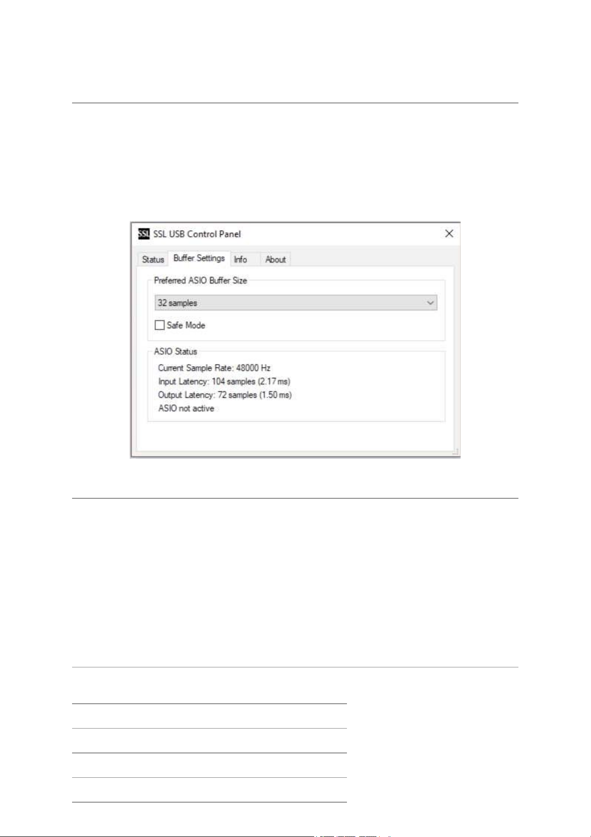
report details such as what Sample Rate and Buffer Size your SSL 12 is running at.
Please note that both Sample Rate and Buffer size will be taken control of by your
DAW when it is opened.
Safe Mode
One aspect you can control from the SSL USB Control Panel is the tickbox for Safe
Mode on the 'Buffer Settings' tab. Safe mode defaults to ticked but can be unticked.
Unticking Safe Mode will reduce the overall Output Latency of the device, which
may be useful if you are looking to achieve the lowest possible roundtrip latency in
your recording. However, unticking this may cause unexpected audio clicks/pops if
your system is under strain.
Specifications
Unless specified otherwise, default test configuration:
Sample Rate: 48kHz, Bandwidth: 20 Hz to 20 kHz
Measurement device output impedance: 40 Ω (20 Ω unbalanced)
Measurement device input impedance: 200 kΩ (100 kΩ unbalanced)
Unless otherwise quoted all figures have a tolerance of ±0.5dB or 5%
Audio Performance Specifications
Microphone Inputs
Frequency Response 20Hz - 20kHz unweighted +/-0.15 dB
Dynamic Range (A-weighted) 111 dB
THD+N (-8dBFS) 0.0015%

Gain Range 62 dB
EIN (A-weighted) -130.5 dBu
Max Input Level +6.5 dBu
Input impedance 1.2 kΩ
Line Inputs
Frequency Response 20Hz - 20kHz unweighted +/-0.1 dB
Dynamic Range (A-weighted) 111.5 dB
THD+N (-1dBFS) (@1kHz) 0.0005%
Gain Range 17.5 dB
Max Input Level +24.1 dBu
Input Impedance 15 kΩ
Instrument Inputs
Frequency Response 20Hz - 20kHz +/-0.1dB
Dynamic Range (A-weighted) 110.5 dB
THD+N (-8dBFS) (@1kHz) 0.0015%
Gain Range 62 dB
Max Input Level +14 dBu
Input Impedance 1 MΩ
Balanced Outputs (Out 1&2 and 3&4)
Frequency Response 20Hz - 20kHz +/-0.05 dB
Dynamic range (A-weighted) >120 dB
THD+N (-1dBFS) (@1kHz) 0.0005%
Maximum Output Level +24 dBu
Output Impedance 75 Ω
Headphone Outputs (A&B) - Standard Mode
Frequency Response 20Hz - 20kHz +/-0.02dB
Dynamic Range (A-weighted) 112dB
THD+N (-1dBFS) (@1kHz) 0.005%

Maximum Output Level +10 dBu
Output Impedance <1 Ω
Headphone Outputs (A&B) - High Sensitivity
Frequency Response 20Hz - 20kHz +/-0.02dB
Dynamic Range (A-weighted) 108dB
THD+N (-1dBFS) (@1kHz) 0.001%
Maximum Output Level -6 dBu
Output Impedance <1 Ω
Headphone Outputs (A&B) - High Impedance
Frequency Response 20Hz - 20kHz +/-0.02dB
Dynamic Range (A-weighted) 112dB
THD+N (-1dBFS) (@1kHz) 0.001%
Maximum Output Level +18 dBu
Output Impedance <1 Ω
Headphone Outputs (A&B) - Line Mode (Balanced)
Frequency Response 20Hz - 20kHz +/-0.02dB
Dynamic Range (A-weighted) 115dB
THD+N (-1dBFS) (@1kHz) 0.005%
Maximum Output Level +24 dBu
Output Impedance <1 Ω
Digital Audio
Supported Sample Rates 44.1, 48, 88.2, 96, 176.4, 192 kHz
Clock Sources Internal, ADAT
USB USB 3.0 for power, USB 2.0 for audio
Low-Latency Monitor Mixing < 1ms
Roundtrip Latency at 96 kHz Windows (Safe Mode Off): 3.3 ms
Mac: 4.9 ms
Physical Specification
Height: 58.65mm
Length: 286.75mm
Depth: 154.94mm
Weight: 1.4kg
Troubleshooting, FAQs, Important Safety Notices
Frequently Asked Questions and additional support contacts can be found on the
Solid State Logic Supportwebsite.
General Safety
Read these instructions.
Keep these instructions.
Heed all warnings.
Follow all instructions.
Do not use this apparatus near water.
Clean only with dry cloth.
Do not install near any heat sources such as radiators, heat registers, stoves
or other apparatus (including amplifiers) that
produce heat.
Unplug this apparatus during lightning storms or when unused for long periods
of time.
Install in accordance with the manufacturer’s instructions.
Only use attachments/accessories recommended by the manufacturer.
Refer all servicing to qualified service personnel. Servicing is required when
the apparatus has been damaged in any way,
such as liquid has been spilled or objects have fallen into the apparatus, the
apparatus has been exposed to rain or moisture,
does not operate normally, or has been dropped.
Do NOT modify this unit, alterations may affect performance, safety and/or
international compliance standards.
Ensure that no strain is placed on any cables connected to this apparatus.
Ensure that all such cables are not placed where
they can be stepped on, pulled or tripped over.
SSL does not accept liability for damage caused by maintenance, repair or
modification by unauthorised personnel.
WARNING: To prevent possible hearing damage, do not listen at high volume levels
for long periods. As a guide to setting the volume level, check that you can still hear
your own voice, when speaking normally while listening with the headphones.
EU Compliance
SSL 12 Audio Interfaces are CE compliant. Note that any cables supplied with SSL
equipment may be fitted with ferrite rings at each end. This is to comply with the
current regulations and these ferrites should not be removed.
Electromagnetic Compatibility
EN 55032:2015, Environment: Class B, EN 55103-2:2009, Environments: E1 - E4.
Audio input and output ports are screened cable ports and any connections to them
should be made using braid-screened cable and metal connector shells in order to
provide a low impedance connection between the cable screen and the equipment.
RoHS notice
Solid State Logic complies with and this product conforms to European Union’s
Directive 2011/65/EU on Restrictions of Hazardous Substances (RoHS) as well as
the following sections of California law which refer to RoHS, namely sections
25214.10, 25214.10.2, and 58012, Health and Safety Code; Section 42475.2, Public
Resources Code.
Instructions for disposal of WEEE by users in the European
Union

The symbol shown here, which is on the product or on its packaging, indicates that
this product must not be disposed of with other waste. Instead, it is the user’s
responsibility to dispose of their waste equipment by handing it over to a designated
collection point for recycling of waste electrical and electronic equipment. The
separate collection and recycling of your waste equipment at the time of disposal will
help to conserve natural resources and ensure that it is recycled in a manner that
protects human health and the environment. For more information aboutwhere you
can drop off your waste equipment for recycling, please contact your local city office,
your household waste disposal service or where you purchased the product.
FCC Compliance
This device complies with part 15 of the FCC Rules. Operation is subject to the
following two conditions: (1) This device may not cause harmful interference, and (2)
this device must accept any interference received, including interference that may
cause undesired operation.
For USA – to the user
Do not modify this unit! This product, when installed as indicated in the
instructions contained in the installation manual,
meets FCC requirements.
Important: This product satisfies FCC regulations when high quality shielded
cables are used to connect with other equipment.
Failure to use high quality shielded cables or to follow the installation
instructions may cause magnetic interference with
appliances such as radios and televisions and will void your FCC authorisation
to use this product in the USA.
Note: This equipment has been tested and found to comply with the limits for a
Class B digital device, pursuant to part 15 of the FCC Rules. These limits are
designed to provide reasonable protection against harmful interference in a
residential environment. This equipment generates, uses and can radiate radio
frequency energy and, if not installed and used in accordance with the instructions,
may cause harmful interference to radio communications. However, there is no
guarantee that interference will not occur in a particular installation. If this equipment
does cause harmful interference to radio or television reception, which can be
determined by turning the equipment off and on, the user is encouraged to try to
correct
the interference by one or more of the following measures:
• Reorient or relocate the receiving antenna.
• Increase the separation between the equipment and receiver.
• Connect the equipment into an outlet on a circuit different from that to which the
receiver is connected. • Consult the dealer or an experienced radio/TV technician for
help.
Industry Canada Compliance
This Class B digital apparatus complies with Canadian ICES-003. Cet appareil
numérique de la classe B est conforme à la norme NMB-003 du Canada.
Evaluation of apparatus based on altitude not exceeding 2000m. There may be
some potential safety hazard if the apparatus is operated at altitude exceeding
2000m.
Evaluation of apparatus based on temperate climate conditions only. There may be
some potential safety hazard if the apparatus is operated in tropical climate
conditions.
Environmental
Temperature: Operating: +1 to 40°C Storage: -20 to 50°C