1
BM19164
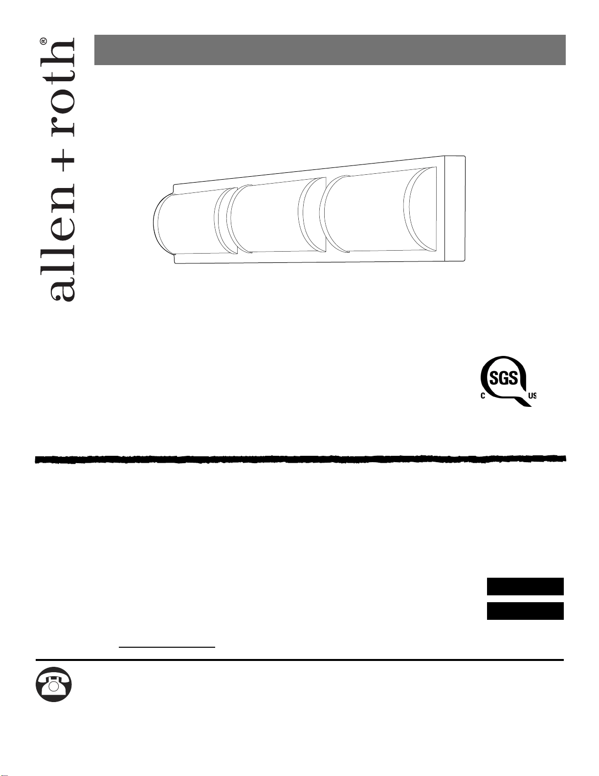
ITEM #1362612
1362621
MODEL #VBL18-3BNK
VBL18-3OSB
3-Light Vanity Bar
Questions, problems, missing parts? Before returning to your retailer, call our customer
service department at 1-866-439-9800, 8 a.m. - 6 p.m., EST, Monday - Thursday,
8 a.m. - 5 p.m., EST, Friday.
Purchase Date
ATTACH YOUR RECEIPT HERE
welcoming • sophisticated • inspiring
allen + roth
®
is a registered trademark
of LF, LLC. All Rights Reserved.
Français p. 10
Español p. 19
APPROVED FOR USE
IN DAMP LOCATIONS
800413
2
Package Contents ................................................................................................................2
Hardware Contents .............................................................................................................
..
3
Safety Information ................................................................................................................3
Preparation
.........................................................................................................................
.
4
Assembly Instructions ...........................................................................................................5
Care and Maintenance .........................................................................................................9
Troubleshooting ..................................................................................................................
.
.
9
Warranty ...............................................................................................................................9
TABLE OF CONTENTS
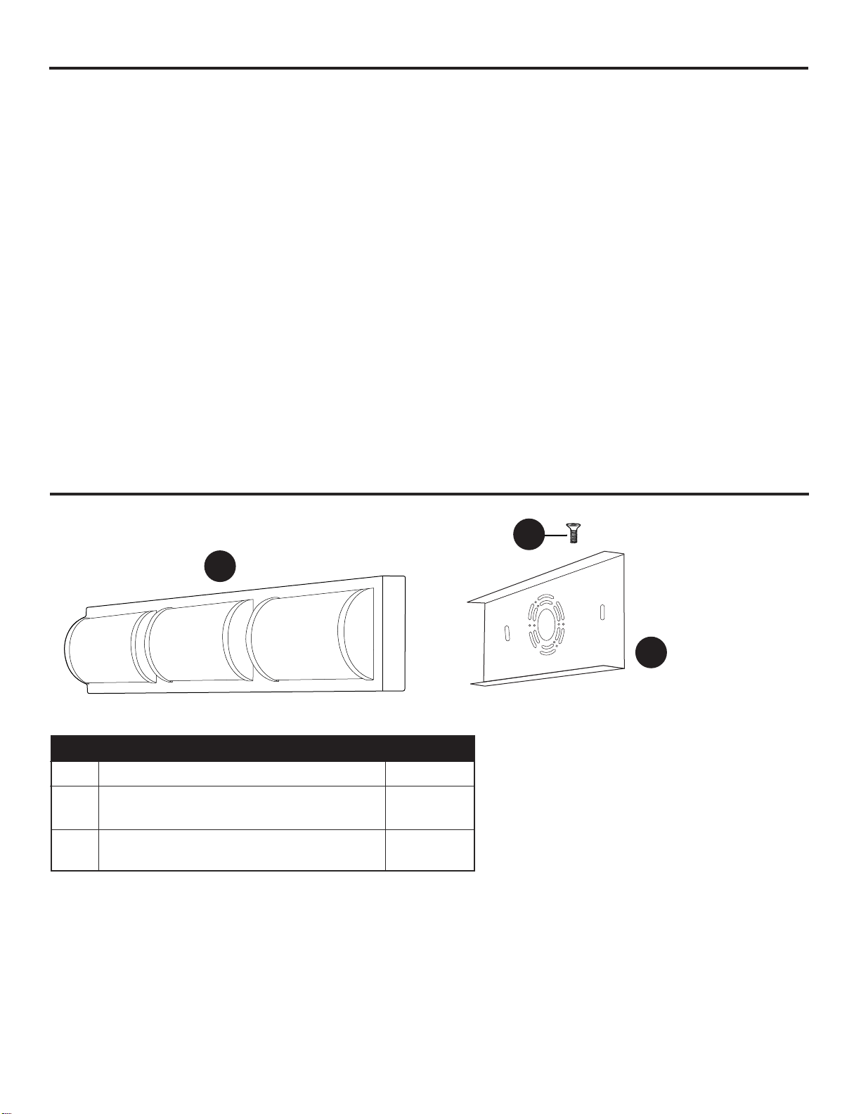
PACKAGE CONTENTS
A Fixture 1
B Mounting Plate 1
(preassembled to fixture (A))
C Mounting Plate Screw 4
(preassembled to fixture (A))
PART DESCRIPTION QUANTITY
A
B
C
READ AND SAVE THESE INSTRUCTIONS.
SAFETY INFORMATION
3
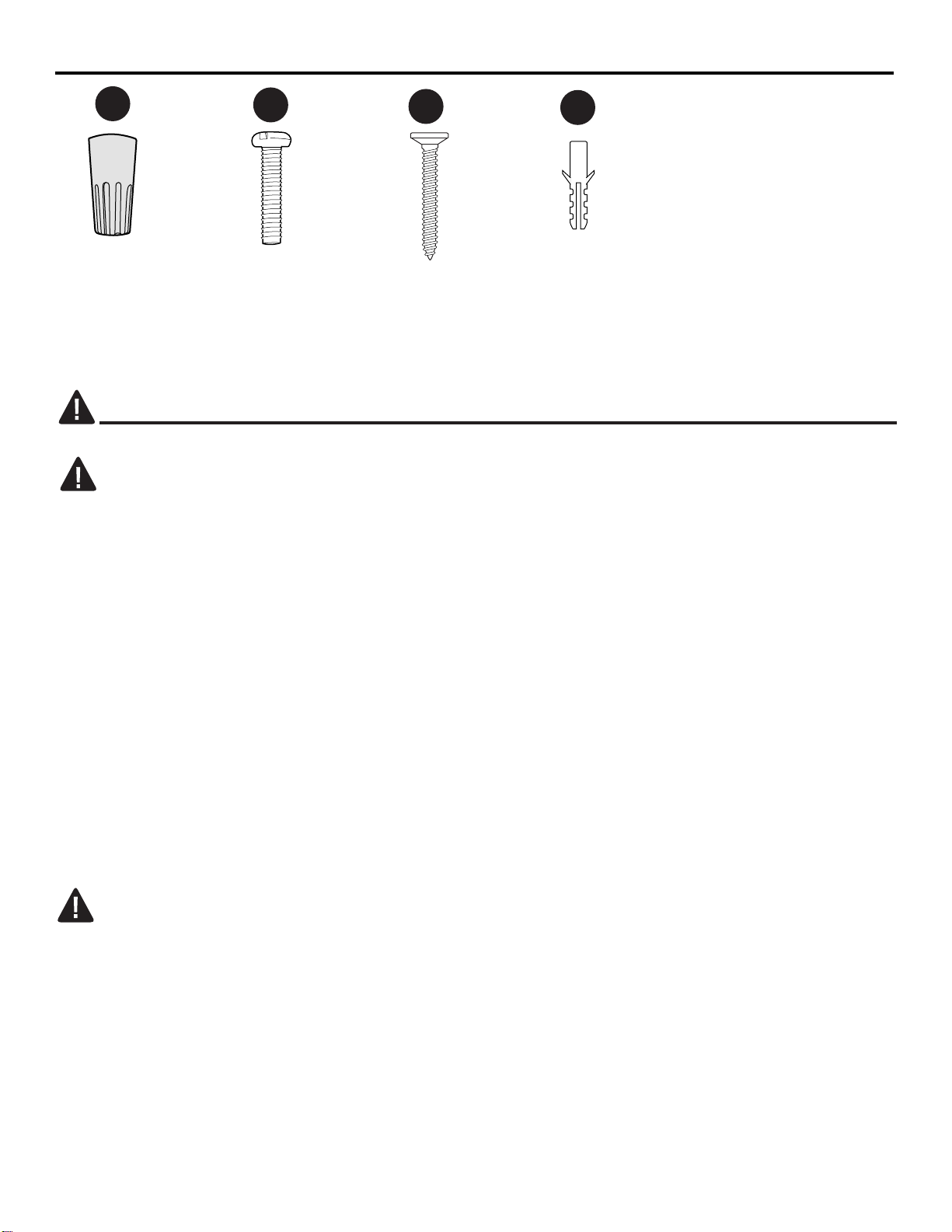
HARDWARE CONTENTS (shown actual size)
• For your protection and safety, carefully read and understand the information provided in this manual
completely before attempting to assemble, install or operate this product. Failure to do so could lead
to fire, electrical shock or other injuries that could be hazardous or even fatal.
• DO NOT connect this fixture to an electrical system that does not provide a means for equipment
grounding. Never use a fixture in a two-wire system that is not grounded. Installing a fixture into an
electrical system not having a proper grounding means could cause metal parts of the fixture to carry
electrical currents if any of the fixture wires, wire connections or splices were to become broken, cut
or loose during the mounting or normal operation of the fixture. Under this condition, anyone coming
in contact with the fixture would be subject to electrical shock, which could cause serious injury or
death.
• DO NOT connect the bare or green insulation fixture ground wire to the black (HOT) current-carrying
wire or the white neutral house wire. Connection of the bare or green fixture ground wire to the black
or white house wires may cause metal parts of the fixture to carry electrical currents. Under this
condition, anyone coming in contact with the fixture will receive electrical shock, which could cause
serious injury or death.
• DO NOT damage or cut the wire insulation (covering) during installation of fixture. DO NOT permit
wires to contact any surface having a sharp edge. To do so may damage or cut the wire insulation,
which could cause serious injury or death from electrical shock.
DANGER
Wire
Connector
Qty. 3
BB
Machine
Screw
Qty. 2
AA
• All electrical connections must be in agreement with local codes and ordinances, the National
Electric Code (NEC) and ANSI/NFPA 70-1999. Contact your municipal building department to learn
about your local codes, permits and/or inspections. Risk of fire - most dwellings built before 1985
have supply wire rated for 140°F. Consult a qualified electrician before installation.
• To avoid personal injury, the use of gloves may be necessary while handling fixture parts with sharp
edges.
• DO NOT suspend any fixture by the house wires. A fixture must always be mounted directly to an
outlet box or to a mounting plate that is first attached to the outlet box. Wire connectors will not
support the weight of a fixture. Suspending a fixture by the house wires and wire connectors will
result in the fixture falling, with the possibility of personal injury and the danger of electrical shock or
fire.
WARNING
Fixture
Screw
Qty. 2
Plastic
Anchor
Qty. 2
CC
DD
4
SAFETY INFORMATION
• To reduce the risk of fire, electrical shock or personal injury, wire connectors provided with this light
fixture are designed to accept only one 12-gauge house wire and two lead wires from the light fixture.
If your house wire is larger than 12-gauge or there is more than one house wire to connect to the
corresponding fixture lead wires, consult an electrician for the proper size wire connectors to use.
• To reduce the risk of damage to the fixture, DO NOT use power tools to assemble any part of the
fixture.
• Note: This equipment has been tested and found to comply with the limits for a Class B digital
device, pursuant to Part 15 of the FCC Rules. These limits are designed to provide reasonable
protection against harmful interference in a residential installation. This equipment generates, uses
and can radiate radio frequency energy and, if not installed and used in accordance with the
instructions, may cause harmful interference to radio communications. However, there is no
guarantee that interference will not occur in a particular installation. If this equipment does cause
harmful interference to radio or television reception, which can be determined by turning the
equipment off and on, the user is encouraged to try to correct the interference by one or more of the
following measures: - Reorient or relocate the receiving antenna. - Increase the separation between
the equipment and receiver. - Connect the equipment into an outlet on a circuit different from that to
which the receiver is connected. Consult the dealer or an experienced radio/TV technician for help.
• TURN OFF ELECTRICITY at main fuse box (or circuit breaker box) before beginning installation by
removing the fuse (or switching the circuit breaker off).
• If you are not sure the lighting system has a grounding means, DO NOT attempt to install this fixture.
Contact a qualified, licensed electrician for information regarding the proper grounding methods as
required by the local electrical code in your area.
• All fixtures must be mounted to an outlet box that is supported by the building structure.
• If a dimmer control switch is used with this fixture, obtain professional advice to determine the
correct type to use as well as the electrical rating required.
• Do NOT tamper with or attempt to repair LED component of fixture. The light source is designed for
this specific application and should not be serviced by untrained personnel. If any servicing is
required, call our customer service department.
WARNING
CAUTION
Before beginning assembly of product, make sure all parts are present. Compare parts with package
contents list and hardware contents list. If any part is missing or damaged, do not attempt to
assemble the product.
Estimated Assembly Time: 30 minutes
Tools Required for Assembly (not included): Flathead Screwdriver, Phillips Screwdriver, Wire
Strippers, Drill, 1/8 in. Drill Bit, Hammer, Pencil, Pliers, Wire Cutters, Safety Glasses, Stepladder,
Electrical Tape
Helpful Tools (not included): A/C Tester Light, Do-It-Yourself Guide, Soft Cloth, Level
PREPARATION
NOTE: Dimmable to 10% with select dimmers. See Lowes.com for more information.
5
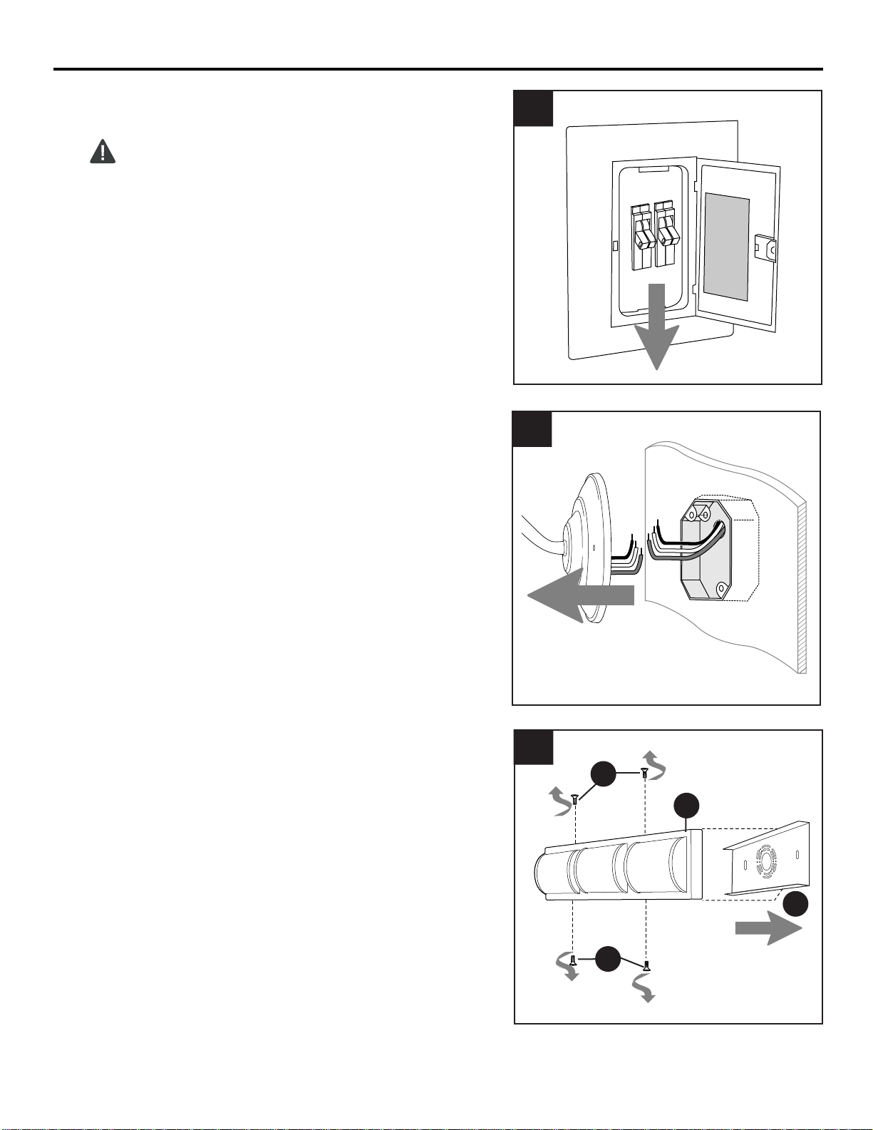
ON
OFF
ON
OFF
Turn off circuit breakers and wall switch to
the fixture supply line leads.
DANGER: Failure to disconnect power
supply prior to installation may result in
serious injury or death.
1
2.
1.
Remove existing fixture and disconnect all
electrical wiring.
2
ASSEMBLY INSTRUCTIONS
Remove mounting plate (B) from fixture (A) by
removing mounting plate screws (C) from the
edges of the fixture (A).
Save mounting plate screws (C) for later use.
3.
3
B
C
A
C
6
4a
B
BB
BB
Outlet Box
Washer
Washer
ASSEMBLY INSTRUCTIONS
Hardware Used
Plastic Anchor
x 2
DD
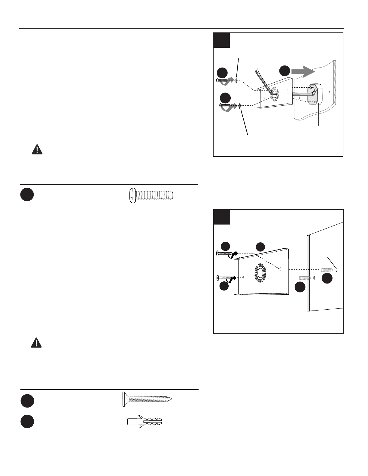
4b.
To mount the item directly to wall, determine the
approximate location for the fixture (A). Place
mounting plate (B) against the wall and mark the
location of the holes using a pencil or a marker (not
included). Set mounting plate (B) aside.
Then, using a 1/8 in. drill bit (not included), drill two
pilot holes at the marked locations. Position plastic
anchor (DD) in each pilot hole. Gently tap plastic
anchors (DD) with a hammer (not included) until
flush with wall surface.
Use a level to adjust mounting plate (B) parallel with
floor and ceiling as needed. Secure mounting plate
(B) to wall with fixture screws (CC).
CAUTION: To mount to wall without an outlet
box, proper wiring for a light fixture must be present
and/or accessible. If not, consult a qualified
electrician before installing the fixture.
CC
x 2
Fixture Screw
To mount the item directly to an outlet box (not
included), attach mounting plate (B) to outlet box
using the existing washers and outlet box screws or
the machine screws (BB). Note: If the outlet box
screws required for your outlet box are of a different
size than the machine screws (BB), consult with a
licensed electrician before proceeding.
Use a level (not included) to make sure mounting
plate (B) is level horizontally (shown) or vertically.
This will help ensure the fixture (A) is level when
attached. Tighten machine screws (BB) completely
to secure mounting plate (B).
CAUTION: Make sure the outlet box can support
35 lbs. hanging weight. Use metal outlet box; plastic
outlet boxes are not recommended.
4a.
Hardware Used
Machine Screw
x 2
BB
DD
Pilot Hole
4b
DD
B
CC
CC
7
ASSEMBLY INSTRUCTIONS
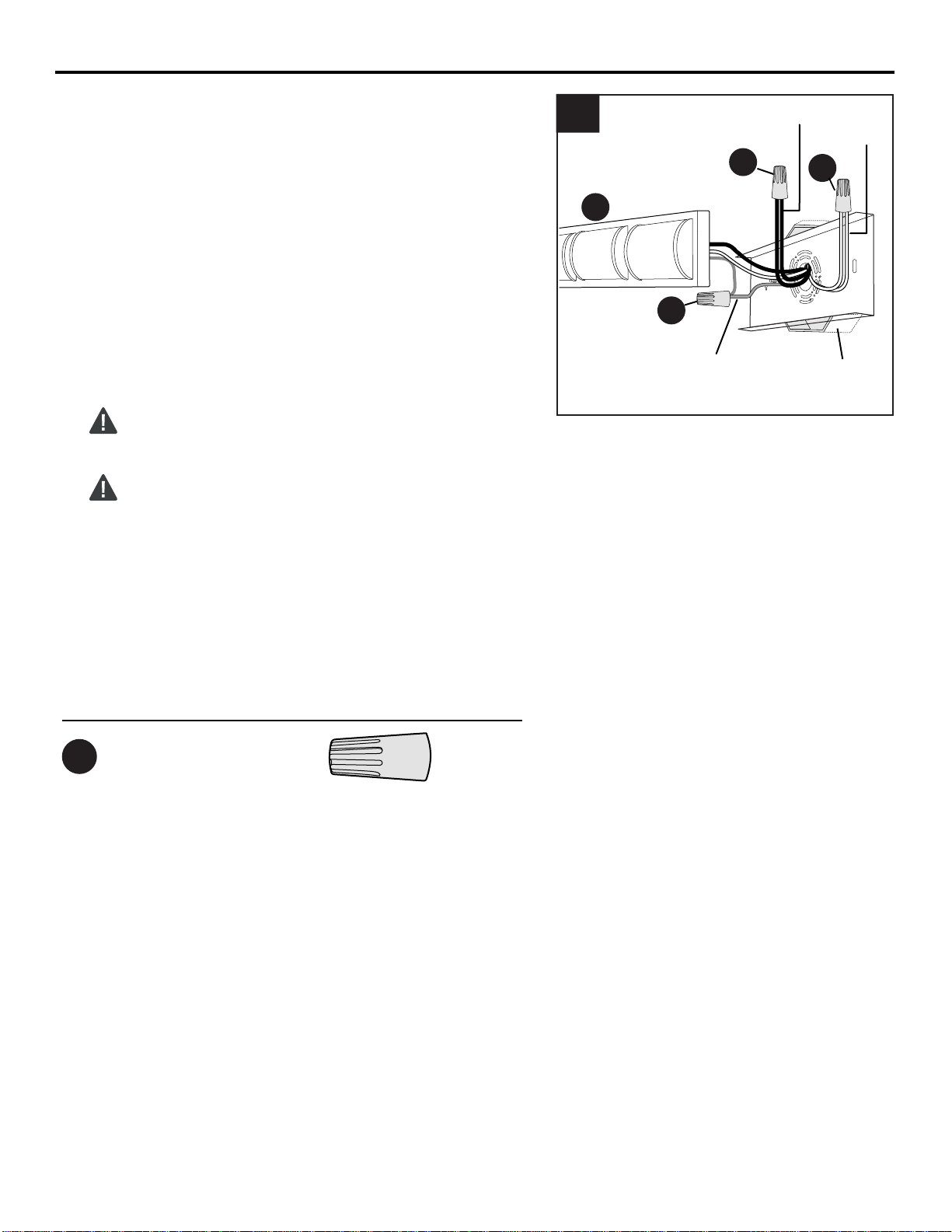
5.
Prepare wires by stripping 1/2 in. of insulation from
wire ends using wire strippers (not included).
Connect BARE/GREEN ground wire from outlet
box to BARE ground wire from fixture (A) with wire
connector (AA). Connect WHITE wire from fixture
(A) to WHITE wire from outlet box using existing
wire connector or wire connector (AA). Connect
BLACK wire from fixture (A) to BLACK wire from
outlet box using existing wire connector or wire
connector (AA).
NOTE: Screw wire connectors (AA) on in a
clockwise direction.
WARNING: Never connect ground wire to
WHITE or BLACK power supply wires.
WARNING: To reduce the risk of fire, electrical
shock or personal injury, wire connectors (AA) are
designed to accept only one 12-gauge house wire
and two lead wires from the light fixture. If your
house wire is larger than 12-gauge or there is
more than one house wire to connect to the
corresponding fixture lead wires, consult an
electrician for the proper size wire connectors to
use.
Hardware Used
Wire Connector
x 3
AA
BLACK
WHITE
BARE/
GREEN
AA
5
A
AA
AA
Outlet
Box
8
ASSEMBLY INSTRUCTIONS
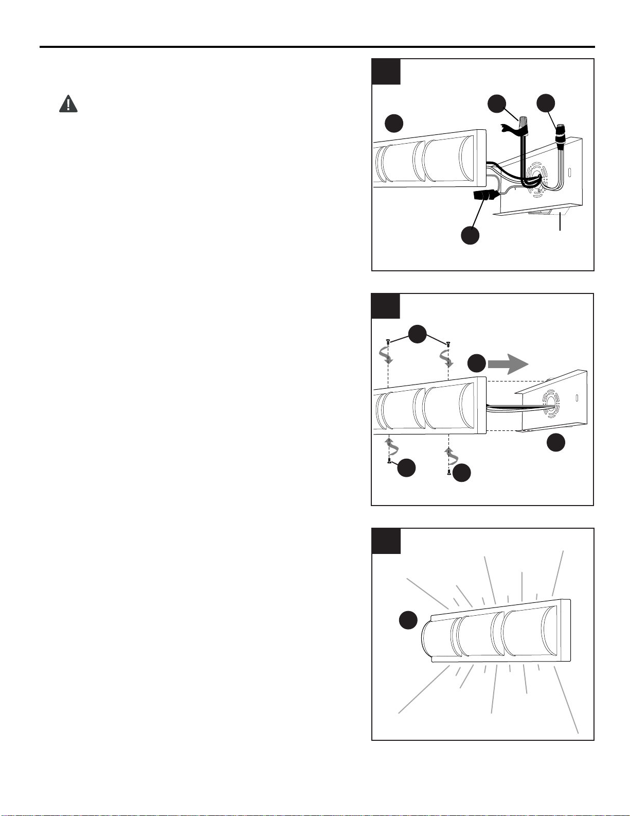
6.
Wrap electrical tape (not included) around each
individual wire connector (AA) down to the wire.
WARNING: Make sure no bare wire or wire
strands are visible after making connections.
Carefully push excess wiring and wire connectors
(AA) gently back into outlet box.
6
AA
A
AA
AA
Outlet
Box
7.
Attach fixture (A) to mounting plate (B) using
the mounting plate screws (C) previously
removed (Step 3, Page 5).
NOTE: Before tightening mounting plate
screws (C) completely, use a level to check
fixture (A) -- adjust if necessary.
Restore power and test fixture (A).
If lights do not function, please refer to
TROUBLESHOOTING on the following page.
8.
8
A
C
7
B
A
C
C
Printed In China
9
WARRANTY
CARE AND MAINTENANCE
WARNING: Before beginning work, shut off the power supply to avoid electrical shock.
• Shut off main power supply. Wipe fixture with soft, damp cloth. Use window cleaner to clean glass.
Do not use an abrasive cleaner on glass or fixture.
• Total wattage for this fixture is 24 watts; do not attempt to replace the LEDs.
TROUBLESHOOTING
The distributor warrants all of its lighting fixtures against defects in materials and workmanship for
five (5) years from the date of purchase. If within this period the product is found to be defective,
take a copy of the bill of sale as a proof of purchase and the product in its original carton to the place
of purchase. The distributor will, at its option, repair, replace or refund the purchase price to the
consumer. All costs of installation and removal of the fixture is the responsibility of the consumer.
This warranty does not cover fixtures becoming defective due to misuse, accidental damage or
improper handling and/or installation and specifically excludes liability for direct, incidental or
consequential damages. As some states do not allow exclusions of limitations on an implied
warranty, the above exclusion and limitation may not apply. This warranty gives you specific rights
and you may also have other rights which may vary from state to state.
KHLI1906
Light does not come on
initially or no longer
comes on.
Fuse blows out or
circuit breaker trips.
1. Power is OFF.
2. Faulty connection.
3. LED component is not working
properly.
1. Crossed wires.
2. Power wire is grounding out.
1. Check wiring.
2. Check all connections.
1. Make sure power supply is ON.
2. Check wiring and all connections.
3. Contact Customer Service.
PROBLEM POSSIBLE CAUSE CORRECTIVE ACTION