Loading ...
Loading ...
Loading ...
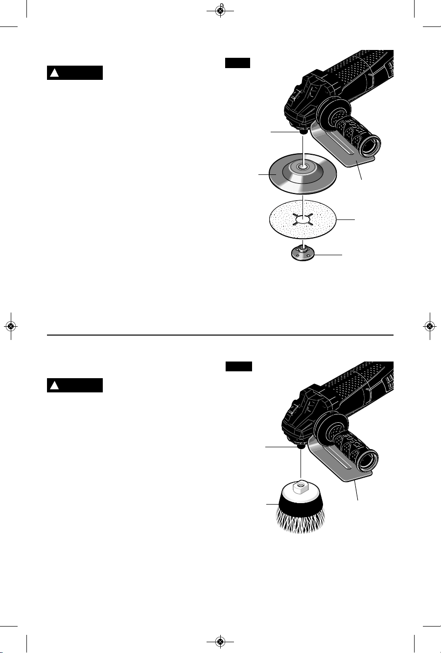
Wire Cup Brush Assembly
A type 27 wheel guard may
not be used for all tool
operations. Do not discard guard when
not in use. Always reinstall wheel guard
when converting back to grinding operations.
The hand shield is to be used with backing
pads, sanding discs and wire brushes to keep
fingers and hand away from work surface,
sharp edges, burs and debris. When using the
hand shield accessory, insert side handle
through hole in shield and then thread into
housing (Fig 4). Ensure that hand shield is
positioned between hand and backing pad,
sanding disc or wire brush.
Do not use a knotted wire cup brush with
this tool. This tool does not have a guard for
knotted wire cup brushes.
To install wire cup brush (Fig. 12):
1. Unplug tool from power source.
2. Attach hand shield.
3. Thread wire cup brush onto spindle until
secure. Be sure to seat cup brush against
shoulder before turning tool “ON”.
TO REMOVE: Reverse procedure.
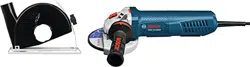
Sanding Assembly
A type 27 wheel guard may
not be used for all tool
operations. Do not discard guard when not
in use. Always reinstall wheel guard when
converting back to grinding operations.
The hand shield is to be used with backing
pads, sanding discs and wire brushes to keep
fingers and hand away from work surface,
sharp edges, burs and debris. When using the
hand shield accessory, insert side handle
through hole in shield and then thread into
housing (Fig 4). Ensure that hand shield is
positioned between hand and backing pad,
sanding disc or wire brush.
To install backing pad and sanding disc
(Fig. 11):
1. Unplug tool from power source.
2. Attach hand shield.
3. Place the rubber backing pad onto the
spindle shaft.
4. Center the sanding disc on top of the
backing pad.
5. Insert the lock nut through the disc and
thread onto spindle.
6. Tighten lock nut with supplied lock nut
wrench while holding spindle lock.
TO REMOVE: Reverse procedure.
SANDING
DISC
BACKING
PAD
LOCK NUT
SPINDLE
FIG. 11
SPINDLE
FIG. 12
WIRE CUP
BRUSH
-17-
!
WARNING
!
WARNING
HAND
SHIELD
HAND
SHIELD
2610041357 09-15 GWS10 GWS13.qxp_GWS series 9/18/15 12:56 PM Page 17
Loading ...
Loading ...
Loading ...