Loading ...
Loading ...
Loading ...
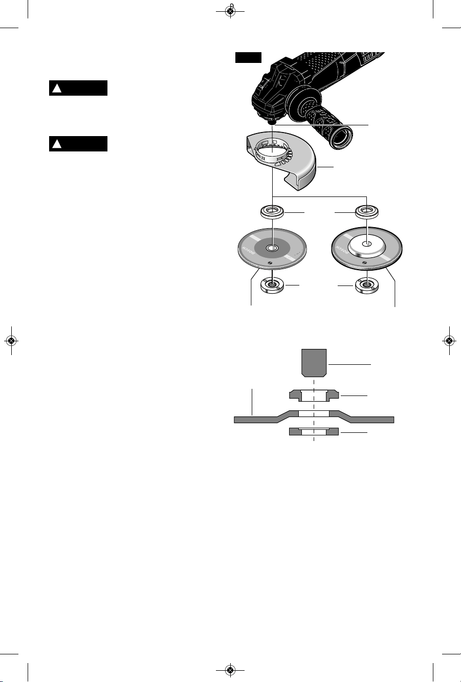
Abrasive Type 41/1A and 27 Cutting
Wheel Assembly
Always use Type 41/1A
cutting guard for cutting
operations. Other guards or attachments may
not protect operator in the event of a wheel
burst.
A type 27 wheel guard may
not be used for all tool
operations. Do not discard guard when not
in use. Always reinstall wheel guard when
converting back to grinding operations.
To install cutting wheel (Fig. 9):
1.Unplug tool from power source.
2.Install and adjust Type 41/1A cutting guard
to the proper position for cutting as shown
in figure 5.
3.Place the backing flange on the spindle.
Turn flange until it locks with the base of the
spindle.
4.Place the cutting wheel onto the spindle
and align the arbor hole of the cutting
wheel with the shoulder of the backing
flange.
5.Thread the lock nut onto the spindle with
the lock nut relief facing the accessory.
6.Tighten lock nut with supplied lock nut
wrench while holding spindle lock.
TO REMOVE: Reverse procedure.
-15-
TYPE 41/1A
WHEEL GUARD
SPINDLE
BACKING
FLANGE
TYPE 41/1A
CUTTING
WHEEL
FIG. 9
LOCK NUT
TYPE 27A
CUTTING
WHEEL
LOCK NUT
TYPE 27A
CUTTING
WHEEL
BACKING
FLANGE
SPINDLE
!
WARNING
!
WARNING
2610041357 09-15 GWS10 GWS13.qxp_GWS series 9/18/15 12:56 PM Page 15
Loading ...
Loading ...
Loading ...