1
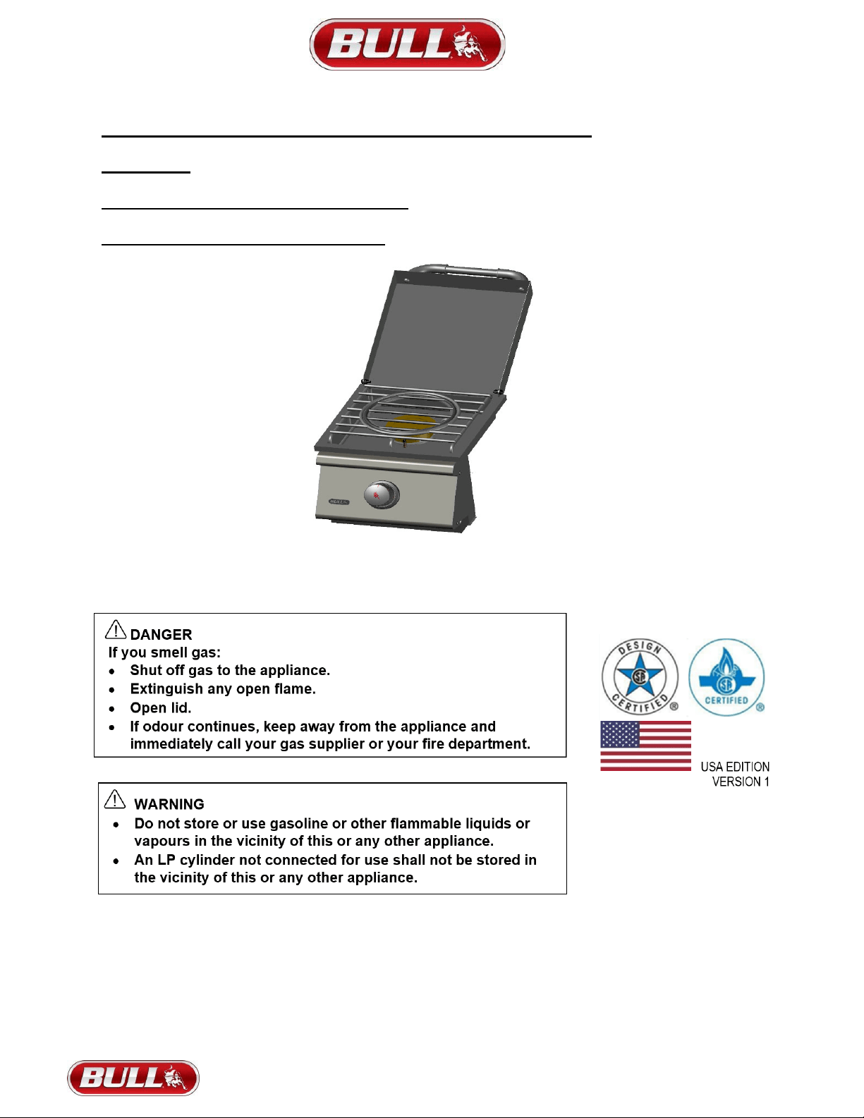
SLIDE-IN PRO SIDE BURNER OWNER’S MANUAL
MODELS
# 60018 LIQUID PROPANE (LP)
# 60019 NATURAL GAS (NG)
2
PLEASE READ THE ENTIRE OWNERS MANUAL CAREFULLY AND RETAIN FOR FUTURE REFERENCE
We care about your safety, so please ….
BE SURE YOUR SIDE BURNER IS PROPERLY INSTALLED ASSEMBLED AND CARED FOR. FAILURE TO FOLLOW INSTRUCTIONS IN THIS
MANUAL MAY RESULT IN SERIOUS BODILY INJURY AND/OR PROPERTY DAMAGE. IF YOU HAVE QUESTIONS CONCERNING
ASSEMBLY OR OPERATION, CONSULT YOUR DEALER OR APPLIANCE SERVICE REPRESENTATIVE FOR ASSISTANCE.
NOTE TO ASSEMBLER, PLEASE RETURN THIS MANUAL TO CONSUMER AFTER INSTALLATION.
NOTE TO CONSUMER, RETAIN THIS MANUAL FOR FUTURE REFERENCE.
THIS SIDE BURNER IS NOT INTENDED FOR USE IN OR ON RECREATIONAL VEHICLES AND OR BOATS.
THIS SIDE BURNER IS NOT INTENDED FOR INSTALLATION OR USE WITH A GRILL CART.
TABLE OF CONTENTS PAGE # 2
HOW TO REGISTER YOUR SIDEBURNER 3
HOW TO ORDER REPLACEMENT PARTS 3
REPLACEMENT PARTS LIST WITH ILLUSTRATION 4
OPERATIONAL SAFETY
SAFETY INSTRUCTIONS, CHECKING FOR GAS LEAKS 5
LIQUID PROPANE SAFETY GUIDELINES 6-8
NATURAL GAS SAFETY GUIDELINES 9
SAFETY GUIDELINES
OPERATING LOCATION AND OVER HEAD VENTILATION 10-11
LIQUID PROPANE GAS CONNECTION 12
LIQUID PROPANE TANK RETENTION 13
NATURAL GAS CONNECTION 14
OPERATING INSTRUCTIONS
FIRST USE OR NEW SEASON GUIDELINES 15-16
STANDARD AND MANUAL LIGHT PROCEDURES 16
COOKING GUIDELINES 16
INSPECTION AND MAINTENANCE
BURNER REMOVAL, INSPECTING AND PORT CLEANING _____________ 17
CLEANING 17
MAINTENANCE 18
TROUBLESHOOTING
YELLOW FLAME AND FLASHBACK 19
LIMITED WARRANTY POLICY
20-22
CREATED 4/2021
3
REGISTERING YOUR SLIDE-IN PRO SIDE BURNER
HOW TO ORDER REPLACEMENT PARTS
This is where your Product Information Reference Card will come in handy for supplying necessary info needed by your Bull Authorized Dealer to
assure you get the correct part(s) for your Side Burner Rotisserie or additional accessories to keep your Side Burner in top working condition. If you
don’t have the card you can still get the Gas grill model number and type of gas hook up used as stated on your Side Burner’s data sticker which is
located on the right side of the grease tray drawer or on the inside of the left side panel as shown in your owner manual. That information is required
for parts orders.
Please refer to your owner’s manual parts list and illustration to identify what you need.
To Order Replacement Parts on-line go to:https://www.bullbbq.com/buy-parts
Ordering Parts by phone: Bull is ready to help with two regional suppliers open 8:00 am to 5:00 pm Monday through Friday.
For the Western Region, please call Bull Grills & Spas at (760) 746-7727 For the Eastern Region. Please call Goodwood Hardware (225) 926-0155
CAUTION: REGARDING CONVERTING YOUR SIDE BURNER FROM LIQUID PROPANE TO NATURAL GAS OR VISA-VERSA.
Your Side Burner gas valve is pre-set at the factory specifically for the gas the Side Burner was intended for. That means a different or specific gas valve
must be installed when converting from one type of gas to another
.
Before you start, be sure to contact your gas supplier or your Bull Grill Dealer who will be ready to supply the correct conversion kits needed.
To validate your Bull Limited Warranty, you must submit the
completed the Warranty Registration Card within 90 days from
the date of purchase. Registration can be completed on-line at
www.bullbbq.com or by sending the completed Warranty
Registration Card and copy of your Purchase Receipt or
Invoice as proof of purchase to:
BULL OUTDOOR PRODUCTS, INC.
2483 WEST WALNUT AVE.
RIALTO, CA 92376
Attn: Warranty Service Center
For Warranty Claims or Replacement Parts ordering, please
fill out the area provided below:
PRODUCT INFORMATION REFERENCE CARD
1) Model Number___________________________________
2) Serial Number ___________________________________
(The Serial Number is encoded with essential information
for ordering replacement parts or submitting Warranty
claims. Location of Serial Numbers is shown below)
3) Date of Purchase______________________
4) Copy of your Purchase Receipt or Invoice.
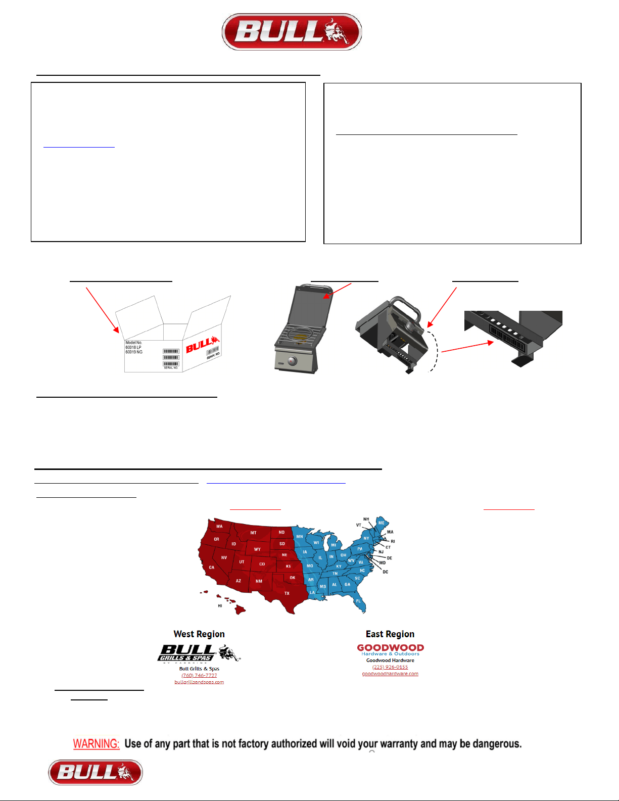
Your Side Burner Model Number and Serial Number are shown in the following locations:
Sides of the Shipping Box Under side of Lid Bottom of Frame
4
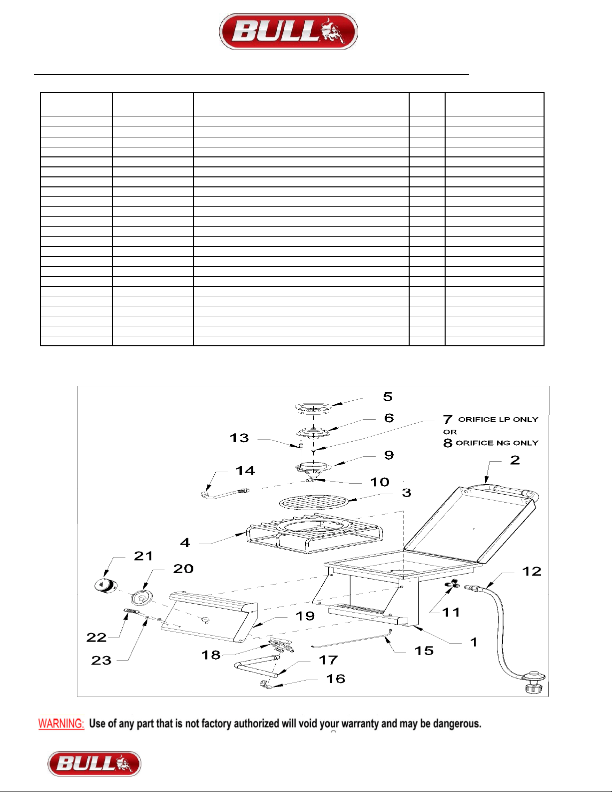
SLIDE-IN PRO SIDE BURNER REPLACEMENT PARTS LIST AND ILLUSTRATION
MODELS # 60018 LP (LIQUID PROPANE) & # 60019 NG (NATURAL GAS)
DWG REF # BULL PART # DESCRIPTION QTY
WARRANTY PERIOD
(SHOWN IN YEARS)
1 60023 PRO BURNER BODY ASSEMBLY 1 1
2 60024 PRO BURNER GRATE COVER 1 1
3 60031 PRO BURNER INNER GRATE 1 1
4 60025 PRO BURNER OUTER GRATE 1 1
5 60026 BURNER TOP 1 1
6 60027 BURNER BASE ‘A’ 1 3
7 60028 ORIFICE LP ONLY (1.5” DIAMETER) 1 1
8 60029 ORIFICE NG ONLY (2.35” DIAMETER) 1 1
9 60030 BURNER BASE ‘B’ 1 1
10 96114 RIGHT ANGLE FITTING 1 1
11 16510 ‘T’ FITTING 1 1
12 16544 LP HOSE (LP TANK TO ‘T’ FITTING) 49.2” LG 1 1
13 96116 IGNITER 1 1
14 95011 SST HOSE (‘T’ FITTING TO BURNER) .35” DIA X 7.8” LG 1 1
15 30013 IGNITER WIRE 9.5” LG 1 1
16 60022 VALVE CLIP 1 1
17 60021 MANIFOLD 1 1
18 16526 BURNER VALVE (LP OR NG) 1 1
19 60020 CONTROL PANEL 1 1
20 16613 KNOB, BURNER CONTROL 1 1
21 16629 BEZEL, ‘BURNER CONTROL KNOB 1 1
22 16571 LOGO PLATE, CONTROL PANEL 1 1
23 16400 LOGO PLATE CLIP 2 1
INSPECT YOUR SIDE BURNER FOR ANY DAMAGE AND CONTACT OUR SERVICE CENTER OR LOCAL DEALER FOR
REPLACEMENT OF ANY DAMAGED PARTS. IF DAMAGED DO NOT ATTEMPT INSTALLATION.
5
SIDE BURNER OPERATIONAL SAFETY
WARNING!
FOR YOUR SAFETY, FOLLOW THE GUIDELINES BELOW:
YOUR GAS SIDE BURNER IS ONLY FOR OUTDOOR USE.
WARNING: DO NOT USE UNDER EXTENDED
AWNINGS, GARAGES, PORCHES, BREEZEWAYS,
SHEDS OR OTHER ENCLOSED AREAS. FAILURE TO DO
SO COULD RESULT IN A FIRE OR PERSONAL INJURY.
DANGER: DO NOT PUT SIDE BURNER IN STORAGE OR
TRAVEL MODE IMMEDIATELY AFTER USE, ALLOW TO COOL
ENOUGH TO TOUCH BEFORE MOVING OR STORAGE. FAILURE
TO DO SO COULD RESULT IN FIRE RESULTING IN PROPERTY
DAMAGE, PERSONAL INJURY OR DEATH.
1) THIS SIDE BURNER IS NOT INTENDED FOR USE IN OR ON
RECREATIONAL VEHICLES AND/OR BOATS.
2) DO NOT PLACE SIDE BURNER UNDER OR ON TOP OF ANY
SURFACE THAT WILL BURN.
3) DO NOT ALLOW OBSTRUCTION OR RESTRICTION TO THE FLOW
OF COMBUSTION AND VENTILATION AIR AROUND THE SIDE
BURNER HOUSING.
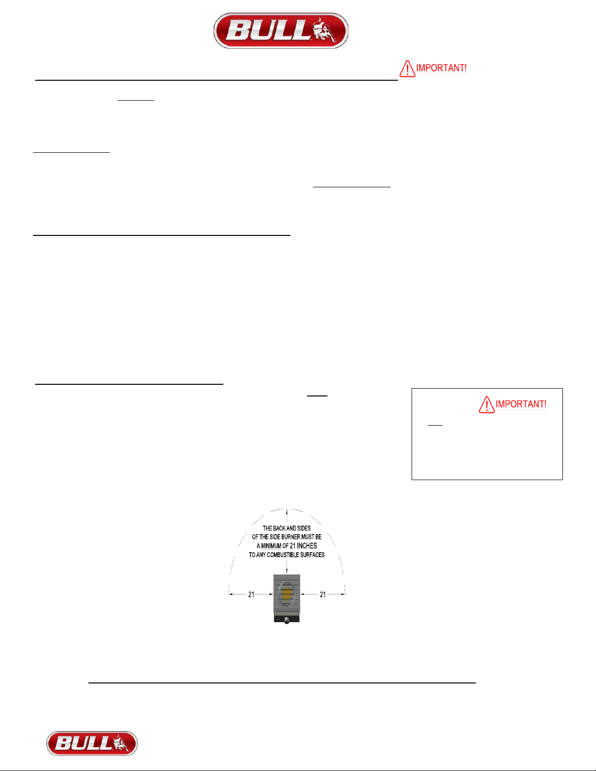
4) SIDE BURNER CLEARANCE FROM THE BACK AND SIDE OF ANY
COMBUSTIBLE SURFACE MUST BE AT LEAST 21 INCHES DO NOT STORE OR USE GASOLINE, OR OTHER LIQUIDS EMITTING
FLAMMABLE VAPOURS IN THE VICINITY OF SIDE BURNER OR ANY OTHER APPLIANCES.
5) DO NOT STORE EMPTY OR FULL SPARE LP GAS CYLINDERS AND/OR CHEMICALS UNDER OR NEAR SIDE BURNER OR ANY
OTHER APPLIANCES.
6) KEEP THE FUEL HOSE AND ELECTRICAL CORDS AWAY FROM HOT SURFACES AND DRIPPING GREASE.
7) CHECK AND CLEAN BURNER TOP, BURNER BASE ‘A’ AND ‘B’ AND ORIFICES FOR INSECTS AND DEBRIS. A CLOGGED TUBE
CAN LEAD TO A FIRE BENEATH THE GRILL. SEE PAGE 4 FOR LOCATION OF THESE PARTS.
8) KEEP THE VENT OPENINGS OF THE CYLINDER ENCLOSURE FREE AND CLEAR FROM DEBRIS.
9) CLEAN OUTDOOR COOKING GAS APPLIANCE WITH RECOMMENDED CLEANING AGENTS.
10) AVOID UNNECESSARY TWISTING OF THE LP HOSE. VISUALLY INSPECT THE LP HOSE PRIOR TO EACH USE FOR CUTS,
CRACKS, EXCESSIVE WEAR OR OTHER DAMAGE AND REPLACE IF NECESSARY. THE REPLACEMENT HOSE SHOULD BE THAT
SPECIFIED BY THE MANUFACTURER
11) ALWAYS REMOVE GRATE COVER BEFORE LIGHTING SIDE BURNER. DO NOT COVER BURNER WITH GRATE COVER UNTIL
SIDE BURNER HAS COMPLETELY COOLED
12) NEVER LEAN OVER COOKING SURFACE WHILE LIGHTING SIDE BURNER.
13) WEAR INSULATED OVEN MITTS AND USE BARBECUE TOOLS WITH WOOD HANDLES WHILE PLACING ITEMS ON SIDE BURNER.
14) NEVER PLACE OBJECTS OR UTENSILS ON TOP OF SIDE BURNER.
15) ALWAYS OPEN SUPPLIED GRATE COVER BEFORE USE. NEVER USE GRATE COVER AS A COOKING SURFACE.
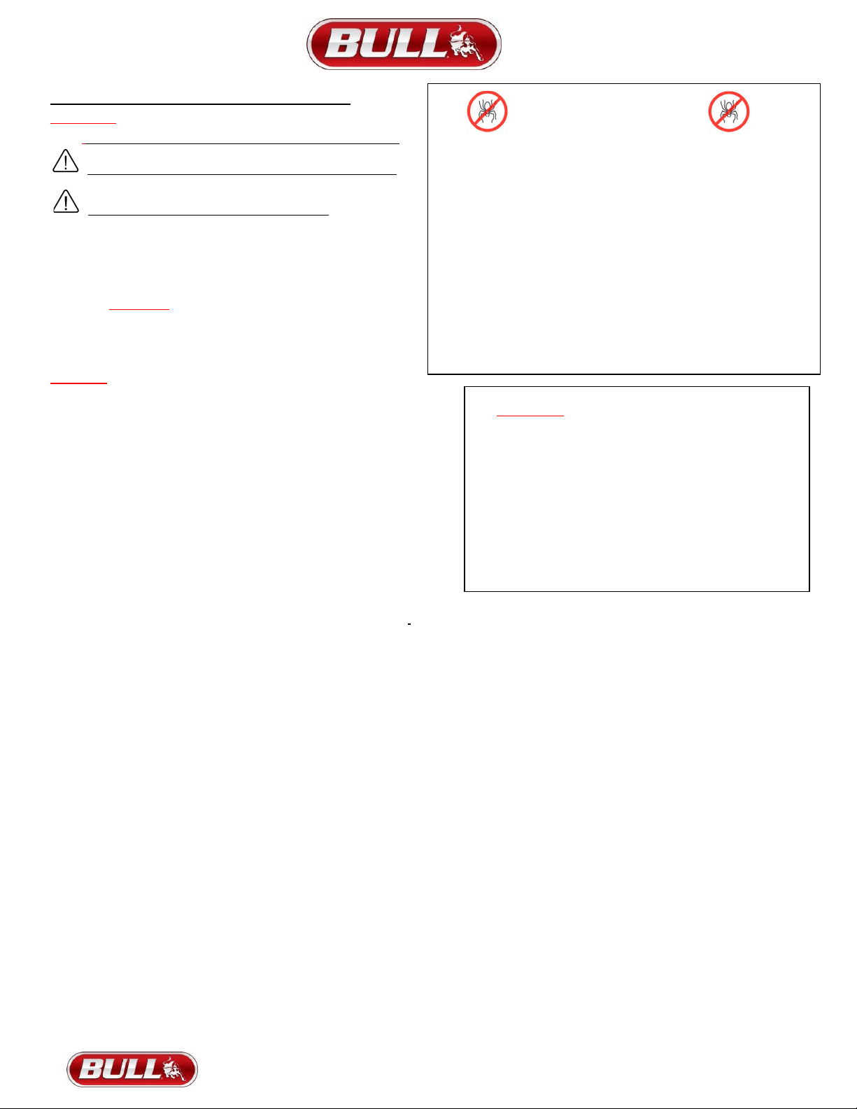
BEWARE OF CLOGGED BURNER
DUE TO SPIDER WEBS
CAUTION: BURNER MUST BE INSPECTED AND CLEANED
BEFORE FIRST USE
Spiders and small insects occasionally spin webs or make
nests in the burner during warehousing, transit and/or after
long periods of non- use. These webs can lead to a gas flow
obstruction, which could result in a fire in and around the
burner venturi tube. This type of fire is known as “FLASH-
BACK” and can cause serious damage to your Side Burner
and create an unsafe operating condition for the user.
Although an obstructed burner tube is not the only cause of
“FLASH BACK” it is the most common cause, and frequent
inspection and cleaning of the burner is necessary
.
WARNING
NEVER cover slots, holes
or passage in the Side
Burner bottom or cover an
entire cooking grate with
material such as aluminium
foil. Doing so blocks air
flow through the oven and
may cause carbon
monoxide poisoning.
Aluminium foil linings may trap
heat causing a fire hazard.
PROTECT CHILDREN FROM SIDE BURNER:
DO NOT ALLOW CHILDREN TO OPERATE SIDE BURNER.
KEEP CHILDREN AWAY FROM SIDE BURNER
DURING USE AND AFTERWARD UNTIL YOU
KNOW IT HAS COOLED COMPLETELY.
6
MODEL 60018 LIQUID PROPANE (LP) SAFETY GUIDELINES
DANGER! IF YOU SMELL GAS, FOLLOW THE GUIDELINES BELOW:
16)
VISUALLY CHECK BURNER FLAME STATUS, AND PILOT BURNER FLAME IF PROVIDED.
17) NEVER TEST FOR GAS LEAKS WITH A LIGHTED MATCH OR OPEN FLAME.
18) SHUT OFF GAS SOURCE TO THE APPLIANCE.
19) EXTINGUISH ANY OPEN FLAME.
CHECKING FOR GAS LEAKS NEVER TEST FOR GAS LEAKS WHILE THE BURNER IS LIT!
IT IS A MUST THAT YOU USE THE STEPS BELOW TO CHECK FOR LEAKS ON LP GAS BURNERS PRIOR TO FIRST USE, START OF A
NEW BBQ SEASON AND
WHENEVER THE GAS CYLINDER IS CHANGED ON LP GAS APPLIANCES.
1)
TURN OFF HEAT CONTROL VALVE(S), AND THEN TURN ON GAS AT SOURCE.
2) MAKE A SOAP SOLUTION BY MIXING ONE-PART LIQUID DETERGENT AND ONE-PART WATER.
3) APPLY THE SOAP SOLUTION TO ALL GAS CONNECTIONS: BUBBLES WILL APPEAR IN THE SOAP SOLUTION IF CONNECTIONS ARE NOT
PROPERLY
SEALED. TIGHTEN CONNECTION FITTINGS OR REPLACE IF NEEEDED.
4) IF YOU HAVE A GAS LEAK THAT YOU CANNOT REPAIR, TURN OFF THE GAS AT THE SOURCE, DISCONNECT FUEL LINE FROM THE GRILL AND
IMMEDIATELY
CALL YOUR GRILL DEALER AND GAS SUPPLIER FOR PROFESSIONAL ASSISTANCE.
YOUR PROPANE GAS GRILL IS DESIGNED TO OPERATE ON PROPANE GAS ONLY, AT A PRESSURE REGULATED AT 11” WATER COLUMN (WC.)
OR 27.4 MBAR
WHEN EQUIPPED WITH THE CORRECT PROPANE ORIFICES ON THE VALVES AND A PROPANE REGULATOR ON THE SUPPLY LINE.
IT IS REQUIRED THAT YOU ONLY USE AN LP GAS CYLINDER MEASURING 12 INCHES IN DIAMETER X 18 INCHES TALL WITH A MAXIMUM CAPACITY
OF 20 LB. IN
THE UNITED STATES, THE LP GAS CYLINDER MUST BE CONSTRUCTED AND MARKED IN ACCORDANCE WITH SPECIFICATIONS
OF THE US DEPARTMENT OF
TRANSPORTATION FOR PROPANE GAS CYLINDERS.
1) ALWAYS KEEP LP GAS CYLINDER SECURELY FASTENED IN AN UPRIGHT POSITION.
2) NEVER CONNECT AN UNREGULATED LP GAS CYLINDER TO THE SIDE BURNER
3) DO NOT SUBJECT LP GAS CYLINDERS TO EXCESSIVE HEAT.
4) DO NOT FILL LP GAS CYLINDER BEYOND 80% FULL.
5) CAUTION: NEVER STORE LP GAS CYLINDERS INSIDE A BUILDING, GARAGE OR IN THE VICINITY OF ANY GAS-BURNING APPLIANCE.
6) WARNING: WHEN THE OUTDOOR COOKING GAS APPLIANCE IS NOT IN USE: THE LP GAS MUST BE TURNED OFF AT THE SUPPLY CYLINDER.
7) DO NOT STORE SPARE LP GAS CYLINDERS UNDER OR NEAR THIS APPLIANCE.
8) SPARE LP GAS CYLINDERS MUST BE STORED OUTSIDE IN AN ADEQUATELY VENTILATED AREA THAT IS ISOLATED FROM THE GRILL.
9) SPARE LP GAS CYLINDERS MUST BE KEPT OUT OF REACH OF CHILDREN AND MUST NOT BE STORED IN A BUILDING, GARAGE OR ANY OTHER
ENCLOSED AREA.
10) STORAGE OF AN OUTDOOR COOKING GAS APPLIANCE INDOORS IS PERMISSIBLE ONLY IF THE CYLINDER IS DISCONNECTED AND
REMOVED FROM THE OUTDOOR COOKING GAS APPLIANCE
11) THE LP GAS CYLINDER MUST BE EQUIPPED WITH AN ARRANGEMENT FOR VAPOR WITHDRAWAL.
12) THE LP GAS CYLINDER MUST INCLUDE A COLLAR TO PROTECT THE CYLINDER VALVE.
13) PLACE DUST CAP ON CYLINDER VALVE OUTLET WHENEVER THE CYLINDER IS NOT IN USE. ONLY INSTALL THE TYPE OF DUST CAP ON THE
CYLINDER VALVE
OUTLET THAT IS PROVIDED WITH THE CYLINDER VALVE. OTHER TYPES OF CAPS OR PLUGS MAY RESULT IN LEAKAGE OF
PROPANE.
IF
GAS
ODOR
PERSISTS, IMMEDIATEL
Y
CONTACT
Y
OU
R
GAS
SUPPLIE
R
OR
Y
OUR
FIRE
DEPARTMENT.
7
LIQUID PROPANE (LP) SAFETY GUIDELINES, CONTINUED
14) DO NOT FILL LP GAS CYLINDER BEYOND 80% FULL. IF WARNING NOTICES 1 AND 2 ARE NOT FOLLOWED, A FIRE CAUSING SERIOUS INJURY
OR DEATH MAY OCCUR
15) CAUTION: CHANGING THE GAS TANKS MUST BE DONE AWAY FROM ANY SOURCE OF IGNITION.
16) LP GAS TANK MUST BE MARKED IN ACCORDANCE WITH THE SPECIFICATIONS FOR LP GAS CYLINDERS, SPHERES AND TUBES FOR
TRANSPORTATION OF DANGEROUS GOODS AND COMMISSION, CAN/CSA- B339, AS APPLICABLE
17) LP GAS TANK CONNECTION DEVICE MUST BE COMPATIBLE WITH OUTDOOR COOKING APPLIANCES.
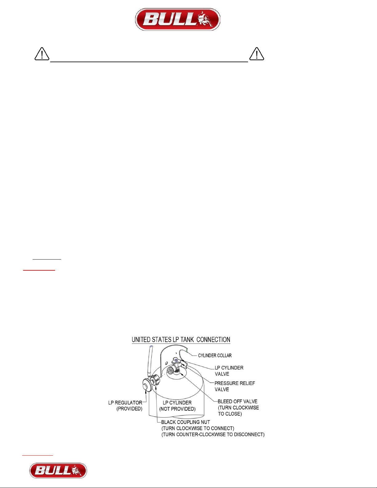
18) LP GAS TANK (CYLINDER) MUST HAVE A LISTED OVERFILLING PREVENTION DEVICE. SEE ILLUSTRATION FOR INSTRUCTIONS 7-11
19) LP GAS TANK(CYLINDER) USES A TYPE 1 TANK VALVE THAT IS FIRMLY SECURED IN AN UPRIGHT POSITION.
20) DO NOT USE AN LP TANK (CYLINDER) THAT IS DAMAGED. VISUALLY INSPECT THE LP HOSE PRIOR TO EACH USE FOR CUTS, CRACKS,
EXCESSIVE WEAR OR DAMAGE. IF FOUND THE HOSE ASSEMBLY SHOULD BE REPLACED.
21) INSPECT LP HOSE FOR PHYSICAL DAMAGE PRIOR TO EACH USE.
22) LP GAS PRESSURE REGULATOR AND 31” INCH HOSE ASSEMBLY (BULL PART # 16589) ARE SUPPLIED AND MUST BE USED WITHOUT
ALTERATION AND SHOULD ONLY BE USED ON YOUR STALLION GRILL.
23) IF THE HOSE ASSEMBLY OR HOSE CLIP NEED TO BE REPLACED, USE ONLY THE BULL PART NUMBERS SHOWN IN THE PARTS LIST SUPPLIED
WITH THIS UNIT.
24) TO CONNECT THE BLACK COUPLING, TURN NUT OF THE HOSE AND REGULATOR ASSEMBLY IN A CLOCKWISE DIRECTION (SEE
ILLUSTRATION BELOW) UNTIL IT IS COMPLETELY THREADED ONTO THE CYLINDER VALVE BEFORE TURNING GAS SUPPLY ON. TO REMOVE
TURN THE BLACK COUPLING NUT OF THE HOSE AND REGULATOR ASSEMBLY IN A COUNTER- CLOCKWISE DIRECTION.
25) IMPORTANT: MAKE SURE THE SIDE BURNER CONTROL KNOB IS IN THE ‘OFF’ POSITION BEFORE CONNECTING TO GAS SOUCE.
WARNING:
GAS VALVES ARE PRE-SET AT THE BULL FACTORY TO OPERATE ON LP GAS OR NATURAL GAS. IF YOU WISH TO CONVERT TO A DIFFERENT GAS
TYPE,
OTHER THAN LP OR NG, BE SURE TO CONTACT YOUR GRILL DEALER, LICENSED PLUMBER OR AUTHORIZED SERVICE CENTER FOR
FURTHER DETAILS.
CONVERSION KITS ARE NOT SOLD TO THE GENERAL PUBLIC AND REQUIRE A PROFESSIONAL TO PERFORM SERVICE.
FAILURE TO PROPERLY CONVERT A
UNIT CAN CAUSE SERIOUS INJURY TO YOURSELF AND/OR OTHERS, IRREPARABLE DAMAGE TO YOUR GRILL
AND VOID OF WARRANTY.
WARNING: IF THESE GUIDELINES ARE NOT FOLLOWED, FIRE CAUSING SERIOUS INJURY OR DEATH MAY OCCUR
8
LIQUID PROPANE (LP) SAFETY GUIDELINES
WHEN THE OUTDOOR COOKING GAS APPLIANCE IS NOT IN USE:
1)
The LP gas must be turned off at the supply cylinder.
2)
Do not store spare LP gas cylinders under or near this appliance.
3)
Spare LP gas cylinders must be stored outside in an adequately ventilated area that is isolated from the grill.
4)
Spare LP gas cylinders must be kept out of reach of children and must not be stored in a building,
garage or any other enclosed
area.
5)
Storage of an outdoor cooking gas appliance indoors is permissible only if the cylinder is disconnected
and removed from the
outdoor cooking gas appliance
6)
The LP gas cylinder must be equipped with an arrangement for vapor withdrawal.
7)
The LP gas cylinder must include a collar to protect the cylinder valve.
8)
Place dust cap on cylinder valve outlet whenever the cylinder is not in use. Only install the type of dust
cap on the cylinder valve
outlet that is provided with the cylinder valve. Other types of caps or plugs may
result in leakage of propane.
WARNING: If these guidelines are not followed, fire causing serious injury or death may occur.
LIQUID PROPANE GAS TO NATURAL GAS CONVERSION
Gas valves are pre-set at the Bull factory to operate on LP Gas or Natural Gas. If you wish to convert to a
different gas type,
other than LP or NG, be sure to contact your grill dealer, licensed plumber or authorized
service center for further details.
Conversion kits are not sold to the general public and require a professional
to perform service. Failure to properly convert a
unit can cause serious injury to yourself and/or others,
irreparable damage to your grill and void of warranty.
WARNING: If these guidelines are not followed, fire causing serious injury or death may occur.
9
MODEL 60019 NATURAL GAS (NG) SAFETY GUIDELINES
Your Natural Gas (G20) grill is designed to use natural gas ONLY. The grill operates at a pressure of 4” water column (wc)
or 10 mbar set at the natural gas regulator attached at the back of the grill. Prior to installing gas supply lines, check with
your local gas utility or municipality regarding local gas pressure and for building code requirements and instructions or
consult a licensed and knowledgeable installer.
NATURAL GAS PLUMBING GUIDELINES:
1) Install an “ON-OFF” shutoff valve for OUTDOOR gas supply source after gas line piping exits outside wall, or before gas
piping enters ground.
2) Install an “ON-OFF” shutoff valve for INDOOR gas supply source to the branch fuel line in an accessible location near the
supply line.
3) Do not use Teflon ® tape or pipe sealant on any flare ends because you will not obtain a leak-free seal.
4) Use only Pipe sealing compound or pipe thread tape of the type resistant to the action of natural gas to at least the first
three threads of all male pipe threads when making the connection.
5) Disconnect your gas grill from fuel source when the gas supply is being tested at high pressures. This appliance and its
individual shutoff valve must be disconnected from the gas supply piping system during any pressure testing of that system
at pressures in excess of 1/2 psig or 37 mbar.
6) Turn off your gas grill when the gas supply is being tested at low pressures. This appliance must be isolated from
the gas supply piping system by closing its individual valve.
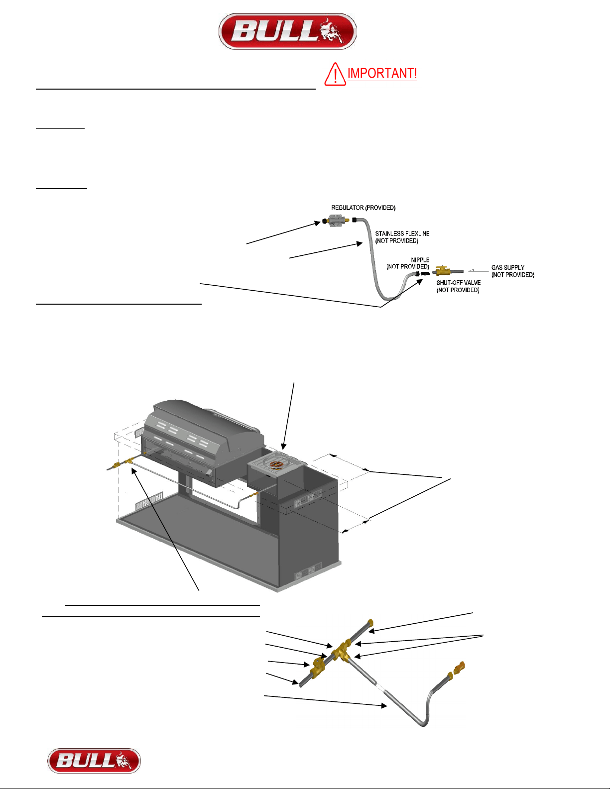
Refer to the following instructions and illustrations for typical gas supply connections.
We strongly suggest professional installation and hook-up of the Gas BBQ. All regulators must meet EN16129 standard.
IMPORTANT: Before connecting grill to gas source, make sure BBQ Grill control knobs are in “OFF” position.
Be sure to follow instructions for connecting an appliance to a fixed fuel piping system specifying the use of a rigid pipe, semi-
rigid tubing, and/or a connector that complies with the Standard for Connectors for Outdoor Gas Appliances and Manufactured
Homes, ANSI Z21.75 For post-mounted outdoor cooking gas appliances, in-ground metallic posts shall be protected against
corrosion as warranted by soil conditions. A suitable coating of corrosion protection will retard the effects of corrosion and help
your Bull purchase last longer.
IMPORTANT: Bull Outdoor Products does not recommend the use of any quick
connect fittings or lines to the unit. Use of
these types of fittings or lines could cause low gas flow and greatly reduce the performance of the unit.
IMPORTANT CONNECTION STEPS:
1) Do not use Teflon tape or pipe sealant on
any flare ends because you will not obtain a
leak free seal.
2) Remove plastic cap from regulator
installed on grill.
3) Attach stainless steel flex line 3/8 flare
female end to the regulator and the
other end to a nipple to allow
connection to a shut-off valve to the
gas supply.
10
SIDE BURNER INSTALLATION AND VENTILATION REQUIREMENTS
READ CAREFULLY BEFORE ASSEMBLY AND OPERATION OF YOUR SLIDE-IN PRO SIDEBURNER
YOUR SLIDE-IN PRO SIDE SIDEBURNER COMES TO YOU FULLY ASSEMBLED. WE STRONGLY RECOMMEND PROFESSIONAL INSTALLATION AND HOOKUP
OF THE SIDEBURNER. THESE INSTRUCTIONS WILL PROVIDE YOU WITH THE MEASUREMENTS NECESSARY FOR YOU OR YOUR BUILDER TO
CONSTRUCT A MASONRY STRUCTURE TO HOUSE YOUR OUTDOOR SIDEBURNER.
NOTE TO INSTALLER: LEAVE THESE INSTRUCTIONS WITH THE CONSUMER FOR FUTURE REFERENCE.
THIS SIDEBURNER MUST BE INSTALLED IN ACCORDANCE WITH ALL LOCAL BUILDING CODES. IN THE UNITED STATES YOUR GAS GRILL MUST BE
INSTALLED IN ACCORDANCE WITH LOCAL CODES OR,
PER THE LATEST EDITION OF THE NATIONAL FIRE PREVENTION ASSOCIATION NFPA 54/ANSI (Z223.1)
IN CANADA, YOUR GAS GRILL MUST BE INSTALLED IN ACCORDANCE WITH LOCAL CODES OR, PER THE LATEST EDITION OF THE CANADIAN STANDARDS
ASSOCIATION CODE CGA B149.2 FOR NATURAL GAS AND PROPANE INSTALLATION OF GAS BURNING APPLIANCES AND EQUIPMENT
ADAPTER FROM 1/2” NPT TO BSP 21 MM & REGULATOR ARE AVAILABLE FROM BULL DEALERS AND DISTRIBUTORS.
SPECIFICATIONS FOR STRUCTURE / ENCLOSURE VENTING:
ANY MASONRY USED FOR CABINET CONSTRUCTION FOR THE STRUCTURE HOLDING THE SIDEBURNER MUST BE NON-COMBUSTIBLE MATERIAL.
1) KEEP IN MIND WHEN CHOOSING A LOCATION FOR YOUR DOUBLE SIDEBURNER THAT IT SHOULD NOT BE LOCATED UNDER ANY OVERHEAD
COMBUSTIBLE CONSTRUCTION.
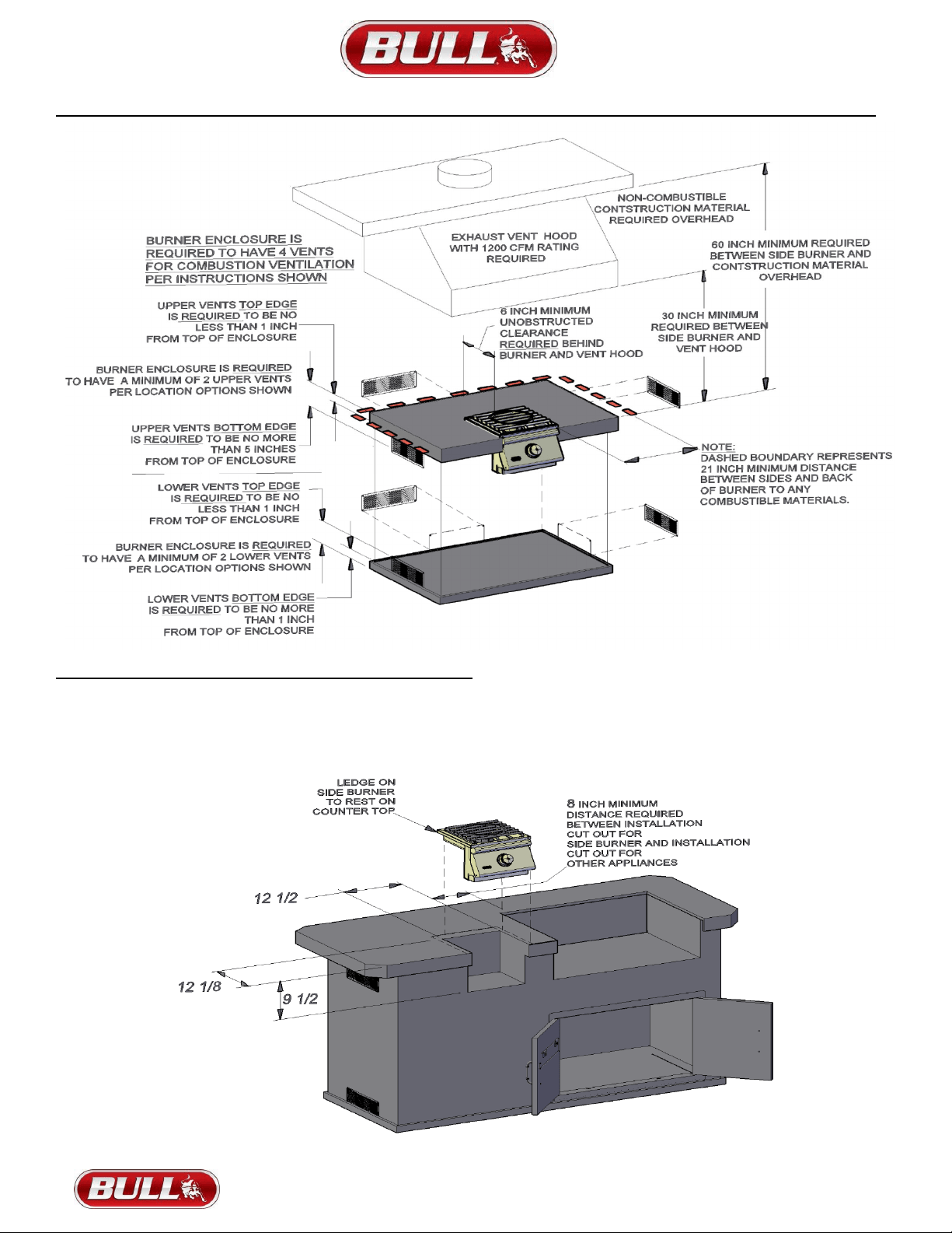
2) UPPER AND LOWER LEVEL VENTS MUST BE PROVIDED FOR COMBUSTION AIR ON BOTH SIDES OF BUILT-IN CABINET. VENTS ON BBQ INSERT MUST
REMAIN UNOBSTRUCTED TO ALLOW FOR COMBUSTION AIR AND VENTILATION.
• UPPER VENTS MUST BE LOCATED WITHIN 5 INCHES FROM THE TOP OF THE ISLAND ENCLOSURE TO THE BOTTOM OF THE VENT. THE UPPER VENTS
MUST HAVE OPENINGS THAT HAVE A TOTAL FREE AREA OF NOT LESS THAN 1 SQ IN PER LB OF STORED FUEL CAPACITY PER VENT
• LOWER VENTS MUST BE LOCATED WITHIN 1 INCH FROM THE BOTTOM OF THE ISLAND ENCLOSURE TO THE BOTTOM OF THE FIRST VENT OPENINGS
AND NO MORE THAN 5 INCHES FROM THE BOTTOM OF THE ISLAND ENCLOSURE TO THE TOP OF THE VENT.
• LOWER VENTS MUST HAVE OPENINGS THAT HAVE A TOTAL FREE AREA OF NOT LESS THAN 1/2 SQ IN PER LB OF STORED FUEL CAPACITY PER VENT.
IF NOT USING BULL VENTS, THE VENTS YOU USE ARE REQUIRED TO MEET ANSI STANDARD CODES. AND BOTH UPPER AND LOWER VENT OPENINGS
MUST HAVE MINIMUM DIMENSIONS SO AS TO PERMIT THE ENTRANCE OF A 1/8 IN DIAMETER ROD.
SPECIFICATIONS FOR OVERHEAD VENTING
IF THE BURNER LOCATION HAS OVER HEAD CONSTRUCTION PRESENT. YOU MUST DO THE FOLLOWING
THESE INSTRUCTIONS:
1) DO NOT INSTALL BURNER UNDER A COMBUSTIBLE COVER.
2) A MINIMUM HEIGHT SEPARATION OF 60 INCHES FROM COOKING SURFACE TO ANY OVERHEAD
CONSTRUCTION IS REQUIRED UNLESS OTHERWISE STATED BY LOCAL BUILDING AND FIRE CODE
REQUIREMENTS.
3) A MINIMUM HEIGHT SEPARTION OF 30 INCHES FROM COOKING SURFACE AND VENTILATION HOOD.
4) VENTILATION HOOD MUST BE LARGER THAN THE COOKING SURFACE WITH A MINIMUM OF 3 INCHES
OF OVERLAP ON EACH SIDE OF COOKING SURFACE.
5) VENTILATION HOOD MUST BE RATED TO OPERATE AT A 1200 CFM (CUBIC FEET PER MINUTE) MINUMUM.
6) MINIMUM HORIZONTAL CLEARANCE TO ADJACENT COMBUSTIBLE SURFACE FROM SIDE AND BACK OF THE SIDE BURNER
MUST BE 21 INCHES.
7) PROVIDE 6 INCHES OF CLEARANCE BEHIND SIDE BURNER TO ALLOW FRONT PORTION OF HOOD TO OPEN AND FOR VENTILATION PURPOSES.
8) THE SIDE BURNER SHOULD NOT BE PLACED UNDER OR ON TOP OF ANY SURFACE THAT WILL BURN.
9) DO NOT OBSTRUCT THE FLOW OF COMBUSTION AND VENTILATION AIR AROUND THE INSERT.
10) LIQUID PROPANE TANK STORAGE AREA MUST BE ISOLATED FROM GRILL AND VENTED
SEE NEXT PAGE FOR REFERENCE DRAWING SHOWING ENCLOSURE AND OVERHEAD VENTILATION DETAILS.
DO NOT PLACE SIDE BURNER IN AN:
ENCLOSED AREA
BREEZEWAY
SCREENED IN PATIO
INDOORS
11
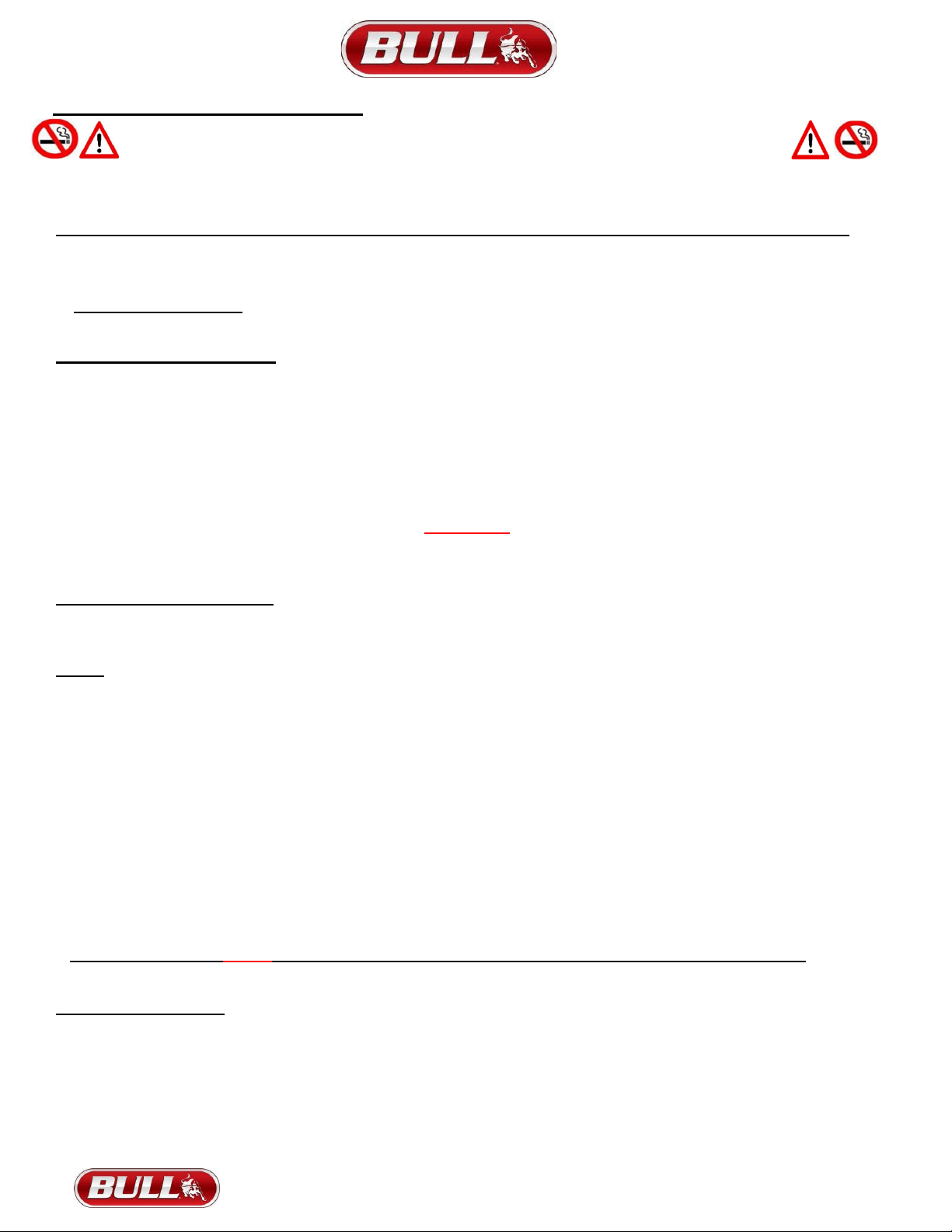
SIDE BURNER ENCLOSURE AND OVERHEAD VENTILATION DRAWING TO THOSE INSTALLING:
SIDE BURNER INSTALLATION TO ENCLOSURE :
1)
ALL DIMENSIONS ARE IN INCHES
2)
INSTALLATION CUTOUT DIMENSIONS ARE 12 1/8 LONG X 9 1/2 WIDE X 12 1/2 DEEP AS SHOWN
3)
FINISHING FRAME FOR SIDE BURNER CAN BE OBTAINED FROM BULL REFER TO ITEM NO. 93007
12
GUIDELINES FOR INSTALLING LP GRILL INTO AN OUTDOOR KITCHEN
1) Vents must be provided for combustion air and ventilation on both sides of built-in cabinet.
2) When choosing a location for your gas grill keep in mind that it should never be located under any overhead combustible construction.
3) Per illustration, the sides and back of the grill should not be any closer than 21 inches to combustible construction.
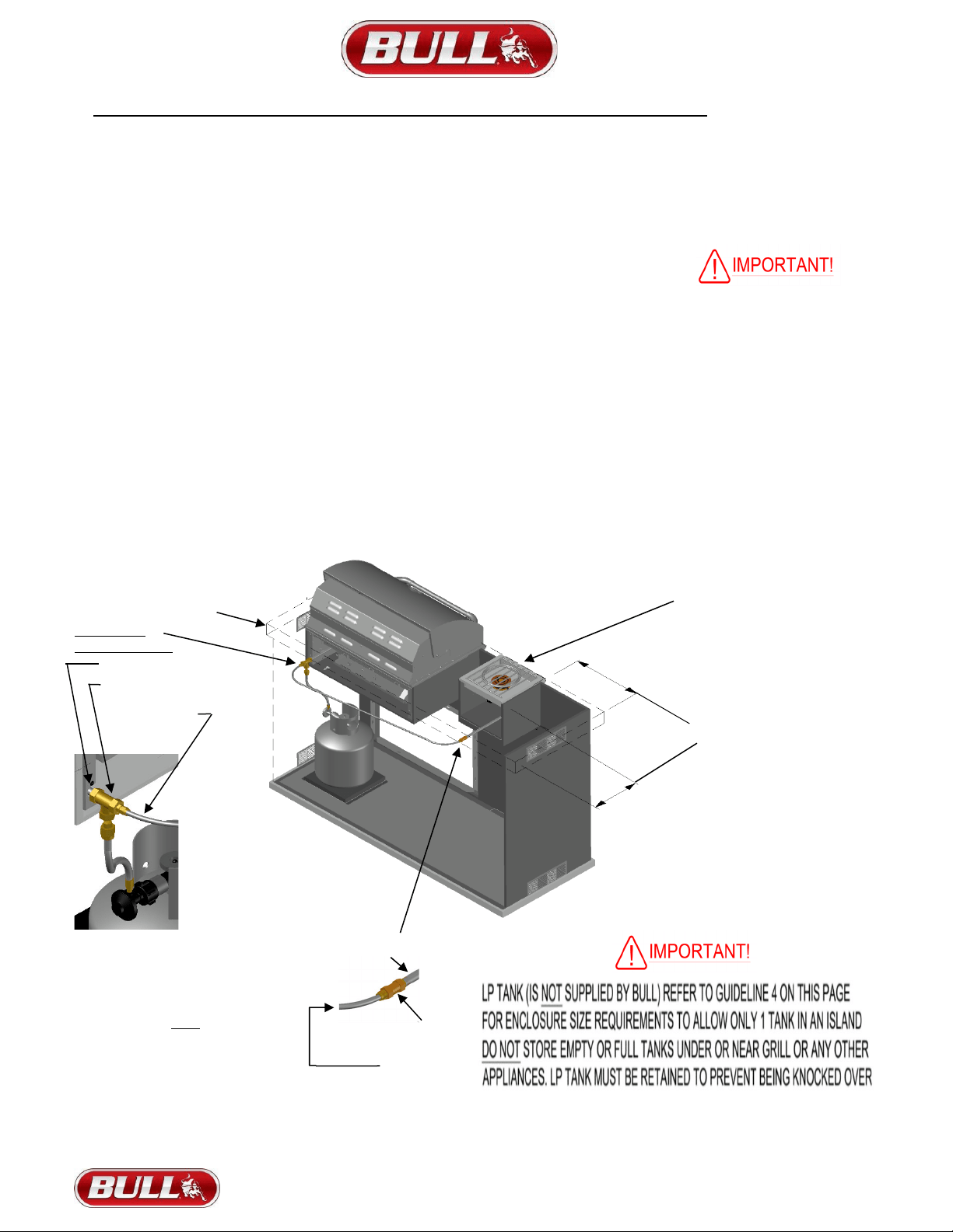
4) Per CSA, it is required that any built-in cabinet must have enough room for only 1 LP tank. The LP tank enclosure must not
exceed (24.5” X 24.5” X 30”) and there must be a minimum clearance of 2 inches between the floor and the propane tank
enclosure.
(DO NOT STORE EMPTY OR FULL SPARE TANKS UNDER OR NEAR THIS OR ANY OTHER APPLIANCE)
5) There must be a minimum of 6 inches counter space behind the grill in order to allow the grill hood to clear properly.
6) The cylinder valve on the LP tank must be readily accessible for hand operation.
7) The LP tank must be isolated enough to where it is shielded from radiant heat and open flames.
8) The LP tank must be protected from foreign matter such as hot drippings.
9) There must be access so the LP tank can be connected, disconnected, inspected and leak tested outside of the cabinet.
10) The enclosure must provide access to allow leak testing of LP connections inside the enclosure for the LP Tank
11) The connectors must comply with ANSI Z21.75 CSA 6.27 standard for Connectors used on Outdoor Gas Appliances and
Manufactured Homes to be suitable for outside installation.
12) The instructions shall indicate that the maximum length of the connection shall be 6 ft.
13) Please ensure visibility of the connector and directions for the piping, flexible tubing and gas connector within enclosure.
14) Do not use any combustible materials for this construction.
NO COMBUSTIBLE
CONSTRUCTION
MATERIALS ALLOWED
WITHIN 21 INCHES OF
THE BACK AND BOTH
SIDES OF SIDE
BURNER OR GRILL
NON-COMBUSTIBLE
CONSTRUCTION REQUIRED
LP PLUMBING
SUPPLIED BY BULL:
GRILL FLEX LINE
3/8 FLARED ‘T’
FITTING
SIDE BURNER LP
LINE
LP HOSE LINE
WITH REGULATOR
SUPPLIED BY BULL
NOTE: LP TANK TO GRILL
AND SIDE BURNER MUST BE
SECURED TO ISLAND
(MOUNTING HARDWARE NOT
SUPPLIED BY BULL)
SIDE BURNER FLEX TUBE
3/8 INCH UNION
FLARE FITTING AND
LP HOSE
SUPPLIED BY BULL
SIDE BURNER
13
LP GAS TANK RETENTION GUIDELINES:
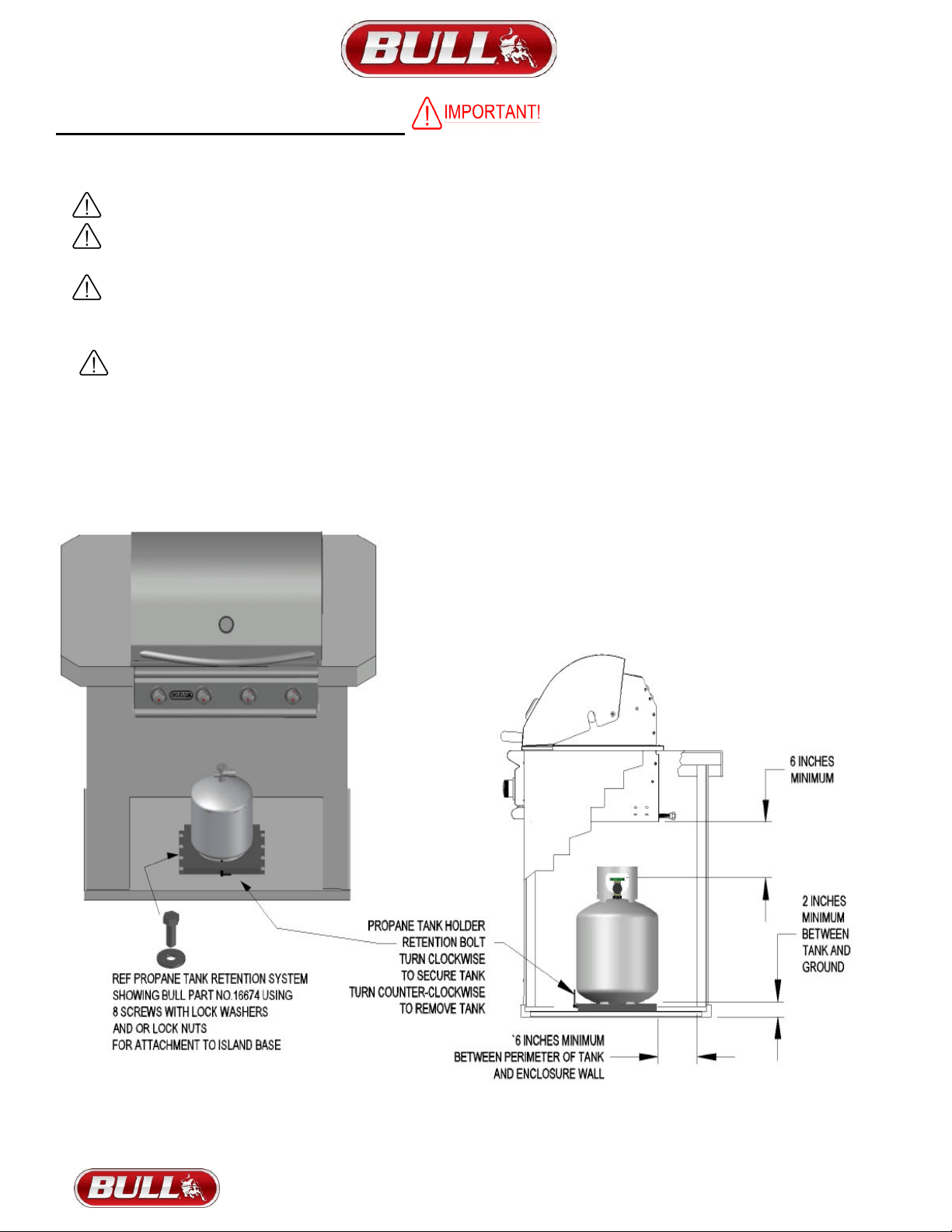
AN LP TANK (CYLINDER) WITHIN AN ENCLOSURE MUST USE A TANK RETENTION SYSTEM TO PREVENT BEING KNOCKED OVER.
Below are guidelines and illustrations for an LP Tank enclosure and how to install a Tank Retention System which can
be obtained through your Bull Dealer:
Any Tank Retention system must be secured to the floor using bolts and nuts or lock washers.
Once secured, place the LP tank in the tank retention system and tighten the tank retention bolt clockwise until the tank is held snug and
cannot move. Turn the retention bolt counter-clockwise to free the tank for removal.
Per CSA, it is required that any built-in cabinet must have enough room for only 1 LP tank.
The LP tank enclosure must not exceed (24.5” X 24.5” X 30”) and there must be a minimum clearance of 2 inches
between the floor and the propane tank enclosure.
WARNING:
DO NOT STORE AN EMPTY, SPARE OR DISCONNECTED LP GAS CYLINDER UNDER OR NEAR THIS GRILL OR ANY OTHER
APPLIANCE.
DO NOT USE A DENTED OR RUSTY LP GAS CYLINDER AS THIS MAY BE HAZARDOUS
DO NOT USE A LP GAS CYLINDER WITH A DAMAGED VALVE OR HOSE.
14
NATURAL GAS (NG) CONNECTION INSTRUCTIONS
Refer to the following instructions and illustrations for typical gas supply connections.
We strongly suggest professional installation and hook-up of the Gas BBQ.
IMPORTANT: Before connecting grill to gas source, make sure BBQ Grill control knobs are in “OFF” position.
Be sure to follow instructions for connecting an appliance to a fixed fuel piping system specifying the use of a rigid pipe, semi-rigid tubing, and/or a
connector that complies with the Standard for Connectors for Outdoor Gas Appliances and Manufactured Homes, ANSI Z21.75 For post-mounted
outdoor cooking gas appliances, in-ground metallic posts shall be protected against corrosion as warranted by soil conditions. A suitable coating of
corrosion protection will retard the effects of corrosion and help your Bull purchase last longer.
IMPORTANT: Bull Outdoor Products does not recommend the use of any quick
connect fittings or lines to the
unit. Use of these types of fittings or lines could cause low gas flow and greatly reduce the performance of the
unit.
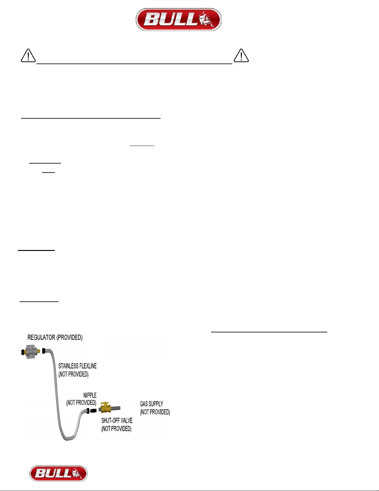
1) Do not use Teflon ® tape or pipe sealant on any flare ends because
you will not obtain a leak-free seal.
2) Remove plastic cap from regulator installed on grill.
3) Attach stainless steel flex line 3/8” flare-female end to the regulator.
4) ``Attach the other end of flex line to shut-off valve through a nipple.
5) Attach a shut-off valve to gas supply pipe.
IMPORTANT INSTALLATION GUIDELINES:
1) Vents must be provided for combustion air and ventilation on both sides of built-in cabinet.
2) When choosing a location for your gas grill, keep in mind that it should never be located under any overhead combustible construction.
3)The sides and back of the grill should not be any closer than 21 inches to combustible construction as shown in drawing below.
4)There must be a minimum of 6 inches counter space behind the grill in order to allow the grill hood to clear properly.
5) Do not use any combustible materials for this construction.
SIDE BURNER
NATURAL GAS CONNECTION PLUMBING TO SIDE
BURNER (THESE PARTS ARE NOT PROVIDED BY BULL)
• 1/2 INCH ‘TEE’ FITING
• 1/2 INCH NIPPLE
• SHUT-OFF VALVE
• 1/2 INCH NIPPLE FROM NATURAL GAS SOURCE
• STAINLESS STEEL FLEX LINE
NO COMBUSTIBLE
CONSTRUCTION
MATERIALS ALLOWED
WITHIN 21 INCHES OF
THE BACK AND BOTH
SIDES OF SIDE
BURNER OR GRILL
STAINLESS STEEL FLEX LINE
3/8-1/2 INCH NPT ADAPTERS
(QUANTITY 2)
15
FIRST USE’ LIGHTING PROCEDURE
NEVER SMOKE WHILE LIGHTING SIDE BURNER OR CHECKING LP GAS CONNECTIONS.
BECOME FAMILIAR WITH THE SAFETY GUIDELINES AT THE FRONT OF THE MANUAL
DO NOT LEAVE SIDE BURNER UNATTENDED DURING USE
IMPORTANT! FOLLOW THE STEPS BELOW BEFORE FIRST USE OR AT START OF NEW GRILLING SEASON
1) If your grill fuel source is LP, verify the gas cylinder is full.
2) Check that the end of the burner tube is properly located over the valve orifice.
3) PERFORM LEAK TEST to ensure that there are no gas leaks before first use, after changing gas tank or start of a new
grilling season.
LEAK CHECK INSTRUCTIONS
1) Turn off heat control valve, and then turn on gas at source.
2) Make a soap solution by mixing one-part liquid detergent and one-part water.
3) Apply the soap solution to all gas connections: bubbles will appear in the soap solution if connections
are not properly sealed. Tighten or repair as necessary.
4) If you have a gas leak that you cannot repair, turn off the gas at the source, disconnect fuel line from the
grill and immediately call your grill dealer and gas supplier for professional assistance.
5) Make sure all gas connections are securely tightened.
WARNING:
IF THESE GUIDELINES ARE NOT FOLLOWED, FIRE CAUSING SERIOUS INJURY OR DEATH MAY OCCUR.
FIRST USE LIGHTING STEPS
Always open lid before lighting. Do not move the appliance when it is in use.
NOTE: The gas line and burner will be full of air after assembly or installation. Before lighting, please follow the
steps below to purge the gas lines and prime them with gas to properly ignite the burners on your grill. It may
require several attempts at lighting the burner before you are successful.
1)
With BBQ Grill control knob in “OFF” position, turn on the Gas supply.
2)
Light the burner by pushing its control knob in fully and slowly (3 to 4 seconds) turning it about 1/4 turn to the
left (counterclockwise) until a click is heard. The 3 to 4 second duration should provide enough gas to light the
burner. Adjust the burner to the desired cooking temperature.
3)
If the burner does not light, immediately return the control knob to “OFF”, wait several minutes for the gas to
disperse, and repeat the process. After burner lights successfully, turn control knob to “OFF”.
4)
If the burner fails to light after several attempts, discontinue gas supply at source and re-inspect for obstructions
to gas flow and orifice. If the burner does not light after several attempts,
immediately (or within 5
seconds?) return the control
knob to ‘OFF’, wait 5 minutes for the gas to disperse
before repeating the
process or attempting to manually light the grill.
IF YOU SMELL GAS, STOP! FOLLOW THE GUIDELINES ON PAGE 6 BEFORE MANUALLY LIGHTING:
MANUALLY LIGHTING
NOTE: If igniter fails to produce a spark at the electrode tip, burner can be manually lit with a fireplace-type match.
NOTE: To light the Side Burner with a fireplace-type match, follow steps 1 through 6 above. Remove cooking grate
and insert lighted fireplace-type match or long-necked butane lighter placing flame near to burner ports. Press in
control knob and rotate left to “HIGH” setting to release gas. Burner should light immediately. Replace cooking
grate and adjust burner to desired cooking temperature.
16
‘FIRST USE’ PROCEDURE
, CONTINUED
IMPORTANT: Before first use and at the end of each barbecue season: wash cooking grate with warm, soapy water. Rinse and dry
thoroughly.
DO NOT RUN FOR MORE THAN 10 MINUTES BEFORE FIRST USE
ALWAYS OPEN LID BEFORE LIGHTING. DO NOT MOVE THE APPLIANCE WHEN IT IS IN USE.
FIRST USE ‘BURN OFF’ GUIDELINES:
A Burn-off process is needed to get rid of any odors or foreign matter before cooking on your Side Burner for the
first time. To do this, ignite the burner and set the control knob to the “HIGH” setting for five minutes, but no more
than 10 minutes before first use, after that turn control knob to “OFF”
NOW YOUR SIDE BURNER IS READY TO USE!
NEVER SMOKE WHILE LIGHTING GRILL OR CHECKING GAS SUPPLY CONNECTIONS!
OPERATIONAL GUIDELINES:
CAUTION: DO NOT LEAVE SIDE BURNER UNATTENDED WHILE IN USE.
CAUTION: The cooking pot sizes to be used are between 4 3/4in(120mm)-8 3/4in(220mm) in diameter. Maximum
weight of pan and contents should not exceed 20 lbs.
It is recommended you use protective gloves during use or handling any components with transferred heat
temperature.
Do not move the appliance when it is in use.
Turn off the gas supply at the gas supply source after usage.
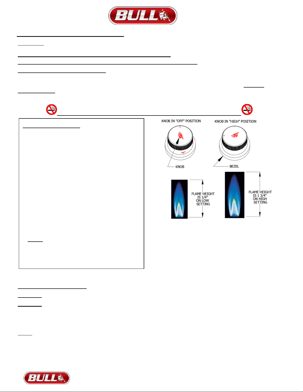
LIGHTING INSTRUCTIONS:
1)
Set ALL BBQ Grill control knobs to “OFF” and
open gas supply, LP cylinder or Natural Gas
Valve.
2)
Ignite only the burners you intend to use, using the
same method for each as follows:
A)
Push in control knob completely and rotate
slowly (3 to 4 seconds) about 1/4 turn to the left
(counterclockwise) until a click is heard. The 3
to 4 second duration should provide enough
gas to light the burner.
B)
If the burner does not light, immediately return
the control knob to ‘OFF’, wait several minutes
for the gas to disperse, repeat the process.
C)
After burner ignites, repeat procedure with any
other burner needed.
D)
Adjust control knob(s) to desired cooking
temperature.
3)
NOTE: Initially, the burner will have a blue
flame (see guidelines below). After
some time, the color of the flame and
Ceramic Panel will be orange.
Note: This may not be evident in bright
dliht
17
SIDE BURNER INSPECTION AND CLEANING
Following these cleaning procedures on a timely basis, will help keep your Side Burner clean and working properly.
CAUTION – ALWAYS TURN OFF THE GAS SUPPLY PRIOR TO CLEARING YOUR SIDE BURNER.
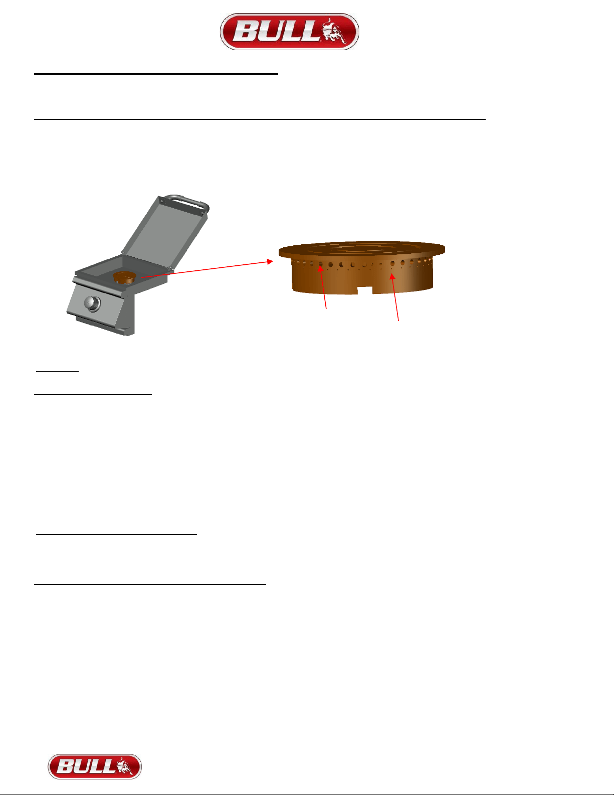
INSTRUCTIONS FOR BURNER REMOVAL, BURNER PORT INSPECTION AND DEBRIS REMOVAL
1) Remove the inner and outer cooking grates.
2) The Burner requires no tools to remove. Burner Port Inspection, the Burner Ports consist of 2 set of holes (one set of large holes and a ring of smaller
holes) as shown below. Visually inspect all of them to insure none are clogged. If there is a clogged port, bend a stiff wire into a small hook and run the
hook through the port several times using a narrow bottlebrush with a flexible handle, run it through the burner openings several times.
3) Inspect the burner for any damage or openings caused by corrosion.
WARNING: Any modification of the appliance is considered dangerous and can cause serious or possible fatal injuries.
CLEANING THE BURNER
IMPORTANT: Gas control knob should be in the “OFF” position, and fuel line should be disconnected from gas valve. To reduce the chance of
FLASHBACK, the procedure below should be followed at least once a month or when your Side Burner has not been used for an extended period of
time.
1) Remove cooking grate and outer ring.
2) Wash the burner ring in a mild soap and warm water solution to remove residue and dirt. Clean any clogged burner ports with a stiff wire such as an
open paper clip.
3) Inspect the burner for damage (cracks or holes) and if such damage is found, order and install a new burner. Clean any clogged burner ports with a
stiff wire such as an open paper clip.
4) After installation, check to ensure that the burner ring is correctly placed on the burner.
CLEANING THE COOKING GRATE CAUTION: ALWAYS ALLOW THE SIDE BURNER TO COOL COMPLETELY BEFORE CLEANING.
IMPORTANT: After cooking, turn control knob to “OFF” and let Side Burner cool before attempting to clean your cooking grate. Before first use and
periodically it is suggested that you wash the cooking grate in a mild soap and warm water solution. You can use a washcloth or a vegetable brush to clean
your cooking grate.
ANNUAL CLEANING OF SIDE BURNER HOUSING
Periodically the Side Burner should be given an entire thorough cleaning to ensure optimal performance.
1) Shut off gas supply at source and disconnect fuel line from gas valve. Protect fuel line fitting.
2) Remove and clean the cooking grate as explained above.
3) Cover the gas orifice with a piece of aluminum foil.
4) Brush the inside of the Side Burner with a brush and wash down with a mild soap and warm water solution. Rinse thoroughly and let dry.
5) Check igniter as instructed on page 16
6) Replace cooking grate.
7)
Reconnect to gas source and observe burner flame for correct operation.
LARGE BURNER
PORT HOLES
SMALL BURNER
PORT HOLES
BURNER
18
MAINTENANCE
REQUIRED INSTALLATION, OPERATION AND MAINTENANCE INSTRUCTIONS THAT MUST BE FOLLOWED PER ANSI
Z210.58-CSA 1.6-2019 SECTION 4.24.2a FOR ALL OUTDOOR COOKING GAS APPLIANCES.
STAINLESS STEEL CLEANING AND MAINTENANCE
Your Side Burner outstanding lustre and durability is attributed to Stainless Steel construction. The Stainless Steel has an outer
layer that relies on a proper cleaning and maintenance routine as the best way to remain intake and prevent corrosion.
Please note, Stainless Steel is not ‘rust proof’ contrary to popular belief. Stainless Steel BBQ equipment is often at risk of
corrosion by exposure to chemicals, caustics and fertilizers from swimming pools and outdoor landscaping. Locations with
climates with greater heat and humidity will intensify this condition. By following a proper cleaning routine, you will add to the
years you enjoy Side Burner.
I. Installation must conform with local codes or, in the absence of local codes, with either of the following as applicable:
a. National Fuel Gas Code, ANSI Z223.1/NFPA 54
b. National Gas and Propane Installation Code, CSA B149.1
c. Propane Storage and Handling Code. CSA B149.2
d. Standard for Recreational Vehicles, ANSI A119.2/NFPA 1192 OR Recreational Vehicle Code, CSA Z240 RV Series
II. If an electrical source is utilized, the outdoor cooking gas appliance, when installed must be electrically grounded in accordance
with local codes, or in the absence of local codes with the refer to National Electrical Code, ANSI/INFPA 70 or Canadian
Electrical Code, Part 1, CSA C22 the following as applicable:
III. This outdoor cooking gas appliance shall be used only outdoors and shall not be used in a building, garage or any enclosed
area.
IV. This outdoor cooking appliance is not intended to be installed in or on boats
V. This outdoor cooking appliance is not intended to be installed in or on recreational vehicles
VI. Do not remove any labels, nameplate or data plate that show the manufacture’s, distributor’s, jobber or dealer’s name,
manufactures address, model name or serial number.
VII. YOUR SIDE BURNER MINIMUM CLEARANCE FROM THE BACK AND SIDE OF ANY COMBUSTIBLE CONSTRUCTION
MUST BE AT 21 INCHES MUST NOT BE UNDER OVERHEAD COMBUSTIBLE CONSTRUCTON.
REFER TO MANUAL PAGES LISTED BELOW FOR GRILL INSPECTION, MAINTENANCE OR SAFETY GUIDELINES:
PAGE 3 & 4 INFO AND LOCATIONS FOR ORDERING REPLACEMENT PARTS
PAGE 10-14 BURNER INSTALLATION, FIELD-INSTALLED PARTS OR ACCESSORIES SUPPLIED WITH THIS OUTDOOR
GAS APPLIANCE.
PAGE 5 CHECKING AND CLEANING OF BURNER/VENTURI TUBES OF INSECTS AND INSECT NESTS.
A CLOGGED TUBE CAN LEAD TO FIRE BENEATH THE GRILL.
REQUIRING OUTDOOR GAS APPLIANCE ARE TO BE CLEAR AND FREE OF COMBUSTIBLE MATERIALS, GASOLINE,
OR OTHER LIQUIDS EMITTING FLAMMABLE VAPOURS.
DO NOT ALLOW OBSTRUCTION OR RESTRICTION TO THE FLOW OF COMBUSTION AND VENTILATION AIR
AROUND THE GRILL HOUSING.
KEEPING THE VENTILATION OPENING OF THE CYLINDER ENCLOSURE FREE AND CLEAR FROM DEBRIS.
KEEPING ELECTRICAL SUPPLY CORD AND FUEL SUPPLY HOSE AWAY FROM ANY HEATED SURFACES.
PAGE 6 GAS LEAK TESTING PROCEDURES
PAGE 7 LP HOSE INSPECTION PRIOR TO EACH USE. ENCLOSED GRILLS MUST HAVE ACCESS TO INSPECT THE HOSE
AND CONNECTIONS. UPON INSPECTION, A HOSE WITH ANY CUTS, SLITS, TEARING, EXCESSIVE ABRASION OR
WEAR. MUST BE REPLACED, DO NOT USE. REFER TO PAGES 3, AND 4 TO ORDER REPLACEMENT LP HOSE.
PAGES 16
INSTRUCTIONS AND ILLUSTRATIONS FOR LIGHTING AND BURNER CONTROL OPERATION.
INSTRUCTIONS AND ILLUSTRATIONS FOR VISUALLY CHECKING THE BURNER AND PILOT FLAME
PAGE 17 BURNER INSPECTION INSTRUCTIONS THAT SHOULD BE DONE MONTHLY.
PAGE 19 IMPORTANTANCE OF BURNER ORIFICE BEING PROPERLY INSERTED INTO THE BURNER TUBE.
.
19
NEVER SMOKE WHILE TROUBLESHOOTING!
TROUBLESHOOTING
IF SIDE BURNER FAILS TO OPERATE PROPERLY
1) TURN OFF GAS AT SOURCE, TURN CONTROL KNOB TO “OFF”, AND WAIT FIVE MINUTES BEFORE TRYING AGAIN.
2) CHECK GAS SUPPLY/CONNECTIONS.
3) REPEAT LIGHTING PROCEDURE.
IF SIDE BURNER STILL FAILS TO OPERATE PROPERLY, TURN “OFF” GAS AT SOURCE, TURN CONTROL KNOB TO “OFF”,
WAIT FOR SIDE BURNER TO COOL, AND CHECK THE FOLLOWING:
A.
MISALIGNMENT OF BURNER TUBE OVER VENTURI TUBE
CORRECTION: REPOSITION BURNER TUBE TO PROPERLY SEAT INSIDE VENTURI TUBE.
B.
OBSTRUCTION IN GAS LINE
CORRECTION: REMOVE FUEL LINE FROM THE SIDE BURNER. NEVER SMOKE AROUND EXPOSED GAS LINE! OPEN GAS
SUPPLY FOR ONE SECOND TO BLOW ANY OBSTRUCTION FROM FUEL LINE. CLOSE OFF GAS SUPPLY AT SOURCE AND
RECONNECT FUEL LINE TO THE SIDE BURNER.
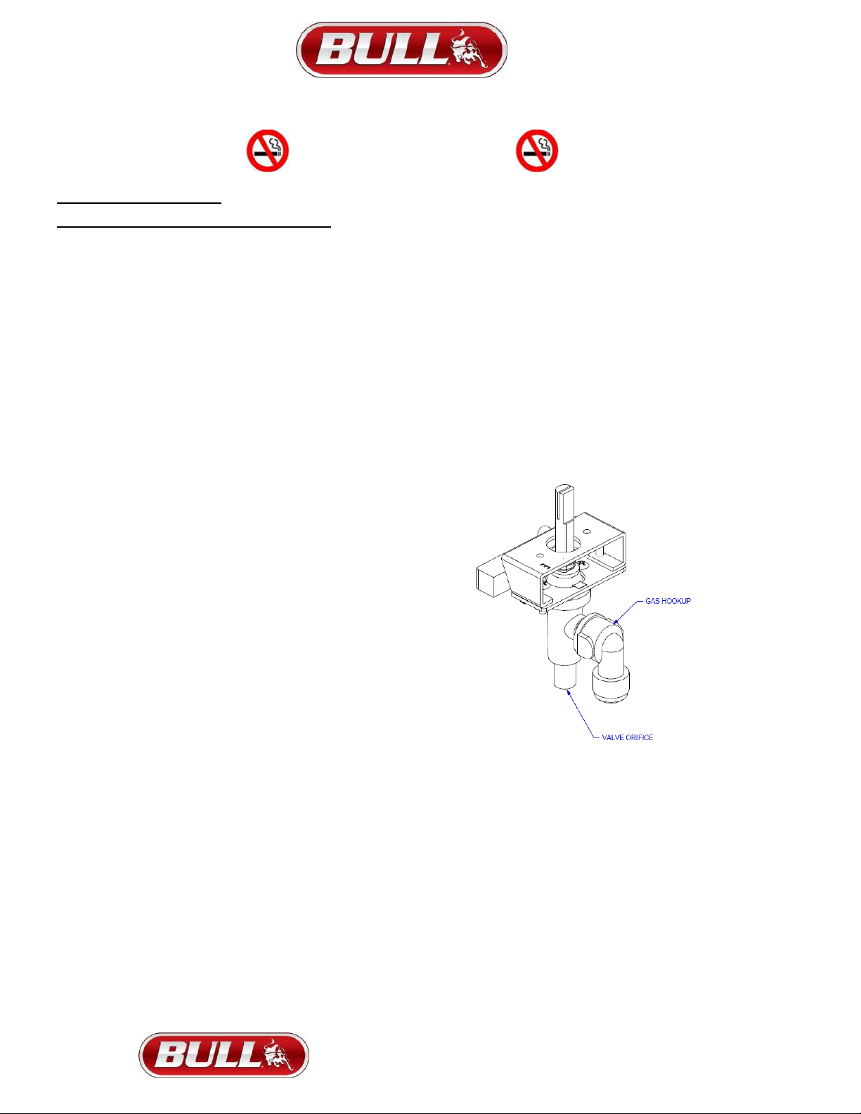
C.
PLUGGED ORIFICE
CORRECTION: REMOVE THE VALVE FROM THE VENTURI TUBE
AND GENTLY CLEAR ANY OBSTRUCTION IN THE ORIFICE WITH A
FINE WIRE. RE-INSTALL THE VALVE INTO THE VENTURI TUBE. IF
AN OBSTRUCTION IS SUSPECTED IN THE GAS VALVE OR THE
VENTURI TUBE, PLEASE CONTACT YOUR SIDEKICK SIDE BURNER
DEALER OR GAS APPLIANCE SERVICE PERSON FOR ASSISTANCE.
D.
MISALIGNMENT OF IGNITER ON BURNER
CORRECTION: CHECK FOR PROPER POSITION OF IGNITER TIP.
THE TIP OF THE IGNITER SHOULD BE RELATIVELY CLOSE TO
THE BURNER PORTS AND FREE FROM GREASE FOR SPARK
DISCHARGING. THE IGNITION WIRE SHOULD BE FIRMLY
CONNECTED TO THE VALVE IGNITION AND IGNITER. REPLACE
THE IGNITION WIRE IF THE WIRE WERE BROKEN OR CRACKED.
WITH GAS SUPPLY CLOSED AND THE CONTROL KNOB SET TO
“OFF”, CHECK THE POSITIVE IGNITER INDIVIDUALLY FOR
PRESENCE OF SPARK AT IGNITER TIP. PUSH THE CONTROL
KNOB IN FULLY AND ROTATE ABOUT 1/4 TURN TO THE LEFT
(COUNTER-CLOCKWISE) UNTIL CLICK IS HEARD; THE TRIGGER
HITTING THE STRIKE BLOCK SHOULD PRODUCE A BLUE SPARK
AT THE IGNITER TIP. RETURN CONTROL KNOB TO “OFF”.
IF RE-IGNITION IS NECESSARY
WHILE THE SIDEKICK SIDE BURNER IS STILL HOT, YOU MUST WAIT FOR A MINIMUM OF FIVE MINUTES BEFORE COMMENCING
TO RE-IGNITE (THIS ALLOWS ACCUMULATED GAS FUMES TO CLEAR). IF ALL CHECKS/CORRECTIONS HAVE BEEN MADE AND
THE SIDEKICK SIDEBURNER STILL FAILS TO OPERATE PROPERLY, CONSULT YOUR SIDEBURNER DEALER OR GAS APPLIANCE
SERVICE PERSON.
FLASHBACK
WHEN FIRE OCCURS IN AND AROUND THE BURNER TUBE, IMMEDIATELY TURN OFF GAS AT ITS SOURCE AND TURN THE CONTROL
KNOB TO “OFF”. WAIT UNTIL THE SIDEKICK SIDEBURNER HAS COOLED COMPLETELY, THEN CLEAN THE BURNER TUBE AS
DESCRIBED ON PAGE 14.
20
LIMITEDWARRANTYONBULLOUTDOORPRODUCTS,INC.,PRODUCTS
THIS LIMITED WARRANTY GIVES YOU SPECIFIC LEGAL RIGHTS.YOU MAY ALS O HAVE OTHER RIGHTS,
WHICHVARYFROMSTATETOSTATE.
THIS LIMITED WARRANTY CAN ALSO BE FOUND ON OUR WEB SITE AT:
https://www.bullbbq.com/support-warranty (United States Customers);
https://www.bullbbq.eu/en/warrantyform.htm (International Customers) AND IN
THEOWNER’S/INSTALLATIONMA NUAL THATWEPROVIDEWITHOURPR ODUCT.
THISLIMITEDWARRANTYISSUBJECTTOTHE EXCLUSIONS,CONDITIONSANDLIMITATIONSSETFORTH
BELOW.
ANY IMPLIED WARRANTIES IMPOSED BY LAW, INCLUDING WITHOUT LIMITATION THE IMPLIE D
WARRANTIES OF MRECHANTABILITY AND FITNESS FOR A PARTICULAR PUR P OSE, ARE LIMITED IN
DURATION TO THEDURATION OF
THIS EXPRESSLIMITEDWARRANTY.SOME STATESDO NOT ALLOW
LIMITATIONS ON HOW LONG AN IMPLIED WARRANTY LASTS, SO THE ABOVE LIMITATION MAY NOT
APPLYTOYOU.
WHOMAYUSETHISWARR ANTY?
BULL OUTDOOR PRODUCTS, INC. located at address 1011 East Pine St. Lodi, CA. 95240
("we") extend this limited warranty only to the consumer who originally purchased the product ("you") at the
original site of delivery or installation. It does not extend to any subsequent owner or other transferee of the
product. It does not apply to products installed in any rental, commercial or non-residential application. Examples
of excluded applications include, but are not limited to day care centers, schools, bed and breakfast centers,
churches, private clubs, fire stations, club houses, common areas in multi-family dwellings, restaurants, hotels,
nursing homes, food service locations and institutional food service locations.
WHATDOESTHISWARRANTYCOVER?
This limited warranty covers defects in materials and workmanship of the product and product components
identified below for the Warranty Periods defined below.
WHATISTHE
PERIODOFCOVERAGE?
This limited warranty starts on the date of your purchase and lasts for the time period or time periods specified
above (the "Warranty Period"). The Warranty Period is not extended if we repair or replace the product. We
may change the availability of this limited warranty at our discretion, but any changes will not be retroactive.

21
GrillWarrantyPeriods
The following parts are covered for oneyear on all our current gas grill models:
The lid, control panel, grease tray, bezels, knobs, temperature gauge, valves, regulator, flex tubes, rotisserie
burner, transformer, and all components of the lighting system.
The following parts are covered for threeyears on all our current gas grill models:
The manifold, handle end caps, flame tamers, heat shields, and warming rack.
The following parts are covered for lifetime on all our current gas grill models:
Insert assembly and the grates.
The warranty period for the grill burners vary by type:
Cast stainless steel burners - lifetime,
Welded burners – 5years, and
Porcelain coated burners – 3years.
The warranty period for the charcoal grill is oneyear on all parts, except for the insert assembly, which is covered
for 5years.
The Bel Air grill included a one‐year warranty on all parts.
ComponentWarrantyPeriods
All of the parts for our components/grill carts/refrigerators/kegerators/drawers/doors are covered for oneyear
with these exceptions:
Power Burner
o The insert/grates are lifetime covered parts.
o The manifold/burner are covered for 3years
.
Searing Station/Slide in Double Sideburner
o The grates are covered for lifetime,
o the insert for 5years, and
o the manifold for 3years.
Single Sideburner
o The grates are covered for 5years and
o the burner for 3years.

22
Sidekick
o The burner is covered for 3years.
PizzaOvens/Islands/FireFeaturesWarrantyPeriods
All of the parts and construction materials are covered for oneyear.
Grill Accessories and Grill Covers do not include a warranty period.
WHATDOESTHISWARRANTYNOTCOVER?
This limited warranty does not cover any damage due to: (a) transportation; (b) storage; (c) improper installation
or use; (d) use on improper fuel/gas supply; (e) failure to follow the product instructions or to perform any
preventive maintenance; (f) modifications; (g) unauthorized repair; (h) normal wear and tear; or (i) external
causes such as accidents, abuse, or other actions or events beyond our reasonable control.
WHATAREYOURREMEDIESUNDE RTHISWARRANTY?
With respect to any defective product claim made during the Warranty Period, we will, in our sole discretion,
either: repair or replace such product (or the defective part) free of charge or (b) refund the purchase price of
such product. We will not pay for shipping charges for repaired or replacement parts, or for any labor or labor
related charges. We will not pay for any accessory products or ancillary products purchased by you for use in
connection with the product.
HOWDOYOUOBTAINWARRANTYSERVICE?
To obtain warranty service, you must submit a warranty claim online through the Bullbq.com website during the
Warranty Period. Warranty claims will not be accepted via email, fax or phone.
LIMITATIONOFLIABILITY
THE REMEDIES DESCRIBED ABOVE ARE YOUR SOLE AND EXCLUSIVE REMEDIES AND OUR ENTIRE
LIABILITY FOR ANY BREACH OF THIS LIMITED WARRANTY. OUR LIABILITY SHALL UNDER NO
CIRCUMSTANCES EXCEED THE ACTUAL AMOUNT PAID BY YOU FOR THE DEFECTIVE PRODUCT, NOR
SHALLWEUNDERANYCIRCUMSTANCESBELIABLE
FORANYCONSEQUENTIAL,INCIDENTAL,SPECIALOR
PUNITIVEDAMAGESORLOSSES,WHETHERDIRECTORINDIRECT.
SOME STATES DO NOT ALLOW THE EXCLUSION OR LIMITATION OF INCIDENTAL OR CONSEQUENTIAL
DAMAGES,SOTHEABOVELIMITATIONOREXCLUSIONMAYNOTAPPLYTOYOU.
Revised 10-15-2020 APR