
IMPORTANT MANUAL Do Not Throw Away
TM
OWNER'S MANUAL
MODEL:
PR1742STA
1, AWNI TR A_TC_R
WARI%TING:
Read the Owner's Manual and follow
all Warnings and Safety Instructions.
Failure to do so can result in serious
injury.
279810 PR 1742STA
Always Wear Eye Protection During Operation
173302 1.6.00 MH
Printed in U.S.A.
SAFETY RULES
Safe Operation Practices for Ride-On Mowers &
IMPORTANT: THIS CUTTING MACHINE IS CAPABLE OF AMPUTATING HANDS AND FEET AND THROWING OBJECTS.
FAILURE TO OBSERVE THE FOLLOWING SAFETY INSTRUCTIONS COULD RESULT IN SERIOUS INJURY OR DEATH.
L
Q
GENERAL OPERATION
Read, understand, and follow all i0structions in the
manual and on the machine beforestarting.
Only allow responsible adults,who arefamiliar withthe
instructions, to operate the machine.
Clear the area ofobjectssuch as rocks,toys, wire, etc.,
which could be picked up and thrown bythe blade.
Be sure the area isclearofotherpeople before mowing.
Stop machine ifanyone enters the area.
Never carry passengers.
Do not mow in reverse unless absolutely necessary.
Always lookdownand behindbeforeandwhile backing.
Be aware of the mower dischargedirection and do not
point it at anyone. Do not operate the mower without
either the entire grass catcher orthe guard in place.
Slow down before turning.
Never leave a runningmachineunattended. Always turn
off blades, set parkingbrake, stopengine, and remove
keys before dismounting.
Turn off blades when not mowing.
Stop engine before removinggrass catcher or unclog-
ging chute.
Mow only in daylight or good artificiallight.
Do not operate themachine whileunder the influance of
alcohol or drugs.
Watch for traffic when operating near orcrossing read-
ways.
Use extra care when loading or unloading the machine
into a trailer or truck.
Data indicates that operators,age 60 years and above,
are involved in a large percentage of riding mower-
related injuries. These operatorsshould evaluate their
abiUty to operate the riding mower safely enough to
protect themselves and othersfrom sedous injury.
II. SLOPE OPERATION
Slopes are a major factor related to loss-of-control and
tipover accidents, which canresultinsevere injuryordeath.
All slopes require extra caution. If you cannot back up the
slope or if you feel uneasy on it, do not mow it.
DO:
• Mow up and down slopes, not across.
• Remove obstacles such as rocks,tree limbs, etc.
• Watch for holes, ruts,or bumps. Uneven terrain could
overturn the machine. Tal/ grass can hide obstacles.
• Uee slow speed. Choose a lowgear sothat you willnot
have to stop or shiftwhile on the slope.
• Follow the manufacturer's recommendations for wheel
weights or counterweights to improve stability.
• Use extra care with grass catchers or other attach-
ments. These can change the stabilityofthe machine.
• Keep all movement onthe slopesslowand gradual. Do
not make sudden changes in speed or direction.
• Avoid starting or stopping on a slope. If tires lose
traction, disengage the blades and proceed slowly
straight down the slope.
2
DO NOT:
• Do not turnon slopesunless necessary, and then, turn
slowlyand graduaUydownhill, ifpossible.
• Do not mow near drop-offs, ditches, or embankments.
The mower couldsuddenlyturnover ifa wheel isoverthe
edge of a cliff or ditch, or ifan edge caves in.
Donotmow onwetgrass. Reduced traction could cause
slidir{g.
• Do not try tostabilizethe machine by putting your foot
onthe ground.
• Do not use grass catcher on steep slopes.
Ill. CHILDREN
Tragic accidents can occurif the operator is not alert to the
presence of children. Children are often attracted to the
machine and the mowing activity. Never assume that
childrenwill remain where you last saw them.
• Keep children out of the mowing area and Under the
watchfulcare of another responsible adult.
• Be alert and turnmachine off if children enter the area.
• Before and when backing, look behind and down for
small children.
• Nevercarrychildren. Theymayfalloffandbeseriously
injuredor interferewith safe machine operation.
• Never allow childrentooperate the machine.
• Useextra carewhen approaching blindcomers, shrubs,
trees, or other objectsthat may obscure vision.
IV. SERVICE
• Use extra care in handling gasoline and other fuels.
They are flammable and vapors are explosive.
Use only anapproved container.
Never remove gas cap or add fuel with the engine
running. Allowengine to cool before refueling, Do
not smoke.
Never refuelthe machine indoors.
Never store the machine or fuel container inside
where there isan open flame, suchas a water heater.
• Never run a machineinside a closed area.
• Keep nuts andbolts, especially blade attachment bolts,
tightand keep equipment in good condition.
• Nevertamperwithsafetydevices. Check their proper
operation regularly.
• Keep machine free of grass, leaves, or other debris
build-up. Cleanoilorfuelspinage. Allowmashinetocool
before stodng.
Stop and inspectthe equipment if you strike an object.
Repair, ifnecessary, before restarting.
• Never make adjustments or repairs with the engine
running.
• Grass catcher components are subject to wear, dam-
age, and detenoretion,whichcouldexpose moving parts
orallow objectstobe thrown. Frequently check compo-
nents and replace with manufacturer's recommended
parts,when necessary.
• Mowerbladesaresharpandcancut. Wraptheblade(s)
or wear gloves, and use extra caution when servicing
them.
• Check brake operation frequently. Adjust and service
as required.
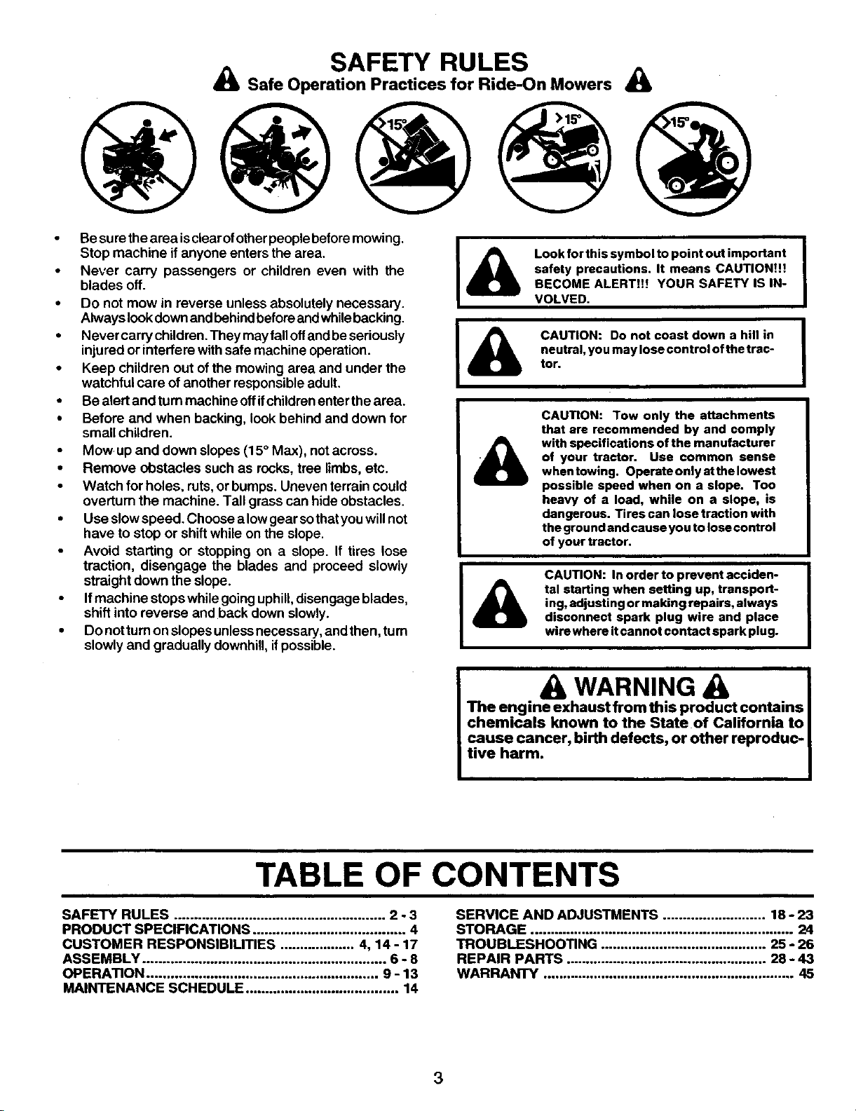
SAFETY RULES
& Safe Operation Practices for Ride-On Mowers &
Besure thearea isclear ofotherpeople beforemowing.
Stop machine if anyone enters the area.
• Never carry passengers or children even with the
blades off.
• Do not mow in reverse unless absolutely necessary.
Always lookdownand behindbeforeandwhilebacking.
• Never carry children.They mayfall offandbe seriously
injured or interfere withsafe machine operation.
• Keep children out of the mowing area and under the
watchful care of another responsible adult.
• Be alert and turn machine offifchildrenenter the area.
• Before and when backing, look behind and down for
small children.
• Mow up and down slopes (15° Max), notacross.
• Remove obstacles such as rocks, tree limbs, etc.
• Watch for holes, ruts,or bumps. Uneven terrain could
overfurn the machine. Tall grass can hide obstacles.
• Use slowspeed. Choose a lowgear sothatyouwillnot
have to stop or shift while on the slope.
• Avoid starting or stopping on a slope. If tires lose
traction, disengage the blades and proceed slowly
straight down the slope.
• Ifmachine stops whilegoinguphill,disengage blades,
shift into reverse and back down slowly.
• Do not turnon slopesunlessnecessary, andthen, turn
slowly and gradually downhill,ifpossible.
Look for this symbol to point out important
safety precautions. It means CAUTION!!!
BECOME ALERT!!! YOUR SAFETY IS IN-
VOLVED.
CAUTION: Do not coast down a hill in
neutral, you may lose control of the trac-
tor.
CAUTION: Tow only the attachments
that are recommended by and comply
with specifications of the manufacturer
of your tractor. Use common sense
when towing. Operate only at the lowest
possible speed when on a slope. Too
heavy of a load, while on a slope, is
dangerous. Tires can lose traction with
the ground and cause you to lose control
of your tractor.
CAUTION: In order to prevent acciden-
tal starting when setting up, transport-
ing, adjusting or making repairs, always
disconnect spark plug wire and place
wire where it cannot contact spark plug.
I
L
& WARNING
The engine exhaust from this product contains
chemicals known to the State of California to
cause cancer, birth defects, or other reproduc-
tive harm.
TABLE OF CONTENTS
SAFETY RULES ...................................................... 2 - 3
PRODUCT SPECIFICATIONS ....................................... 4
CUSTOMER RESPONSIBILITIES ................... 4, 14- 17
ASSEMBLY .............................................................. 6 - 8
OPERATION ........................................................... 9 - 13
MAINTENANCE SCHEDULE ....................................... 14
SERVICE AND ADJUSTMENTS .......................... 18 - 23
STORAGE ................................................................... 24
TROUBLESHOOTING .......................................... 25 - 26
REPAIR PARTS ................................................... 28 - 43
WARRANTY ................................................................ 45
3
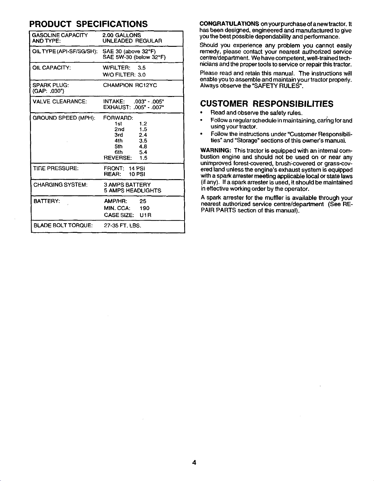
PRODUCT SPECIFICATIONS
GASOLINE CAPACITY 2.00 GALLONS
AND TYPE: UNLEADED REGULAR
OILTYPE(API-SF/SG/SH): SAE 30 (above 32°F)
SAE 5W-30 (below 32°F)
OILCAPACITY: W/FILTER: 3.5
W/O FILTER: 3.0
SPARKPLUG: CHAMPION RCI2YC
GAP: .030")
VALVE CLEARANCE: INTAKE: .003" -.005"
EXHAUST: .005" - ,007"
GROUND SPEED (MPH): FORWARD:
Ist 1.2
2nd 1.5
3rd 2.4
4th 3.5
5th 4.8
6th 5.4
REVERSE: 1.5
TIRE PRESSURE: FRONT: 14 PSI
REAR: 10 PSI
CHARGING SYSTEM: 3 AMPS BATTERY
5 AMPS HEADLIGHTS
BATTERY: AMPiHR: 25
MIN. CCA: 190
CASE SIZE: U 1R
BLADE BOLT TORQU E: 27-35 FT. LBS.
CONGRATULATIONS onyourpumhaseofanewtrector. It
has been designed, engineered and manufactured to give
you the best possibledependability and performance.
Should you experience any problem you cannot easily
remedy, please contact your nearest authorized service
centre/department We have competent, well-trained tech*
niciansand the propertoolsto service or repair this tractor.
Please read and retain this manual. The instructionswill
enable you toassemble and maintain your tractor properly.
Always observe the =SAFETY RULES".
CUSTOMER RESPONSIBILITIES
• Read and observe the safety rules.
Followa regularschedule inmaintaining, cad-ngforand
using yourtractor.
• Followthe instructionsunder "Customer Responsibili-
ties"and "Storage" sections ofthis owner's manual
WARNING: This tractor is equipped with an internal com-
bustion engine and should not be used on or near any
unimproved forest-covered, brush:covered or grass-cov-
ered land unless the engine's exhaust system isequipped
witha spark arrester meeting applicable local or state laws
(ifany). Ifa spark arrester isused, itshould be maintained
ineffective workingorder by the operator.
A spark arrester for the muffler is available through your
nearest authorized service centre/department (See RE-
PAIR PARTS section ofthis manual).
4
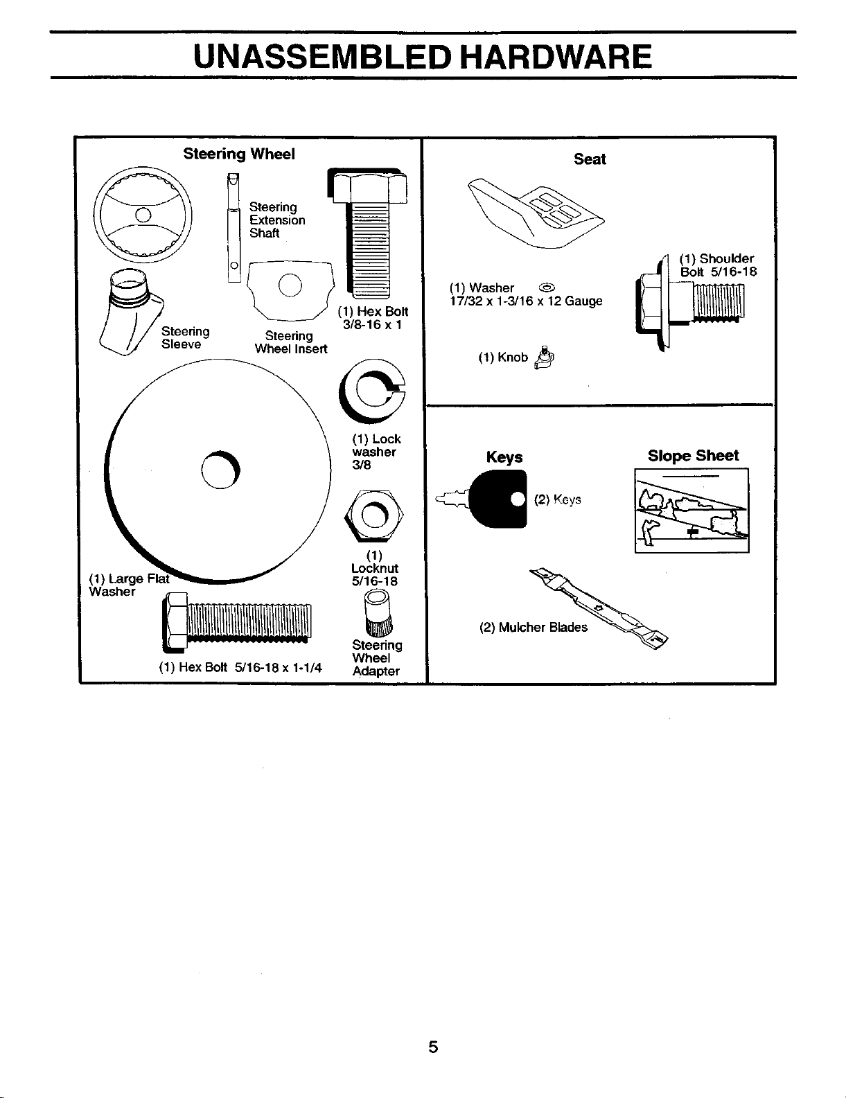
UNASSEMBLED HARDWARE
Steering Wheel
_Steedng
leeve
= Steering
Extension
Shaft
]L°-_ (1) Hex_Bolt
3/8-16 x 1
Steering
Wheel Insert
washer
3/8
Washer
_ Et
Steedng
Wheel
(1) Hex Bolt 5/16-18 x 1-1/4 Adapter
Seat
(1) Washer
17/32 x 1-3/16 x 12 Gauge
(1) Knob
(1) Shoulder
r_ Bolt 5/16-18
Keys
(2) KGys
Slope Sheet
(2) Mulch_
5
ASSEMBLY
Yournew tractorhas been assembled at the factory withexception ofthose parts leftunaseembled for shippingpurposes. To
ensure safe and proper operation of your tractor all parts and hardware you assemble must be tightened securely. Use the
correct tools as necessary to insure proper tightness.
TOOLS REQUIRED FOR ASSEMBLY
A socket wrench set willmake assembly easier. Standard
wrench sizes are listed.
(2) 1/2" wrenches Utility knife
(2) 9/16" wrench Tirepressuregauge
Phillipsscrewdriver
When rightor lefthand ismentioned inthis manual, itmeans
when you are in the operating position (seated behind the
steering wheel).
TO REMOVE TRACTOR FROM CARTON
UNPACK CARTON
• Remove all accessible loose parts and parts cartons
from carton.
• Cut, from top to bottom, along lines on all four corners
of carton, and lay panels flat.
• Check for any additional loose parts or cartons and
remove.
BEFORE REMOVING TRACTOR FROM
SKID
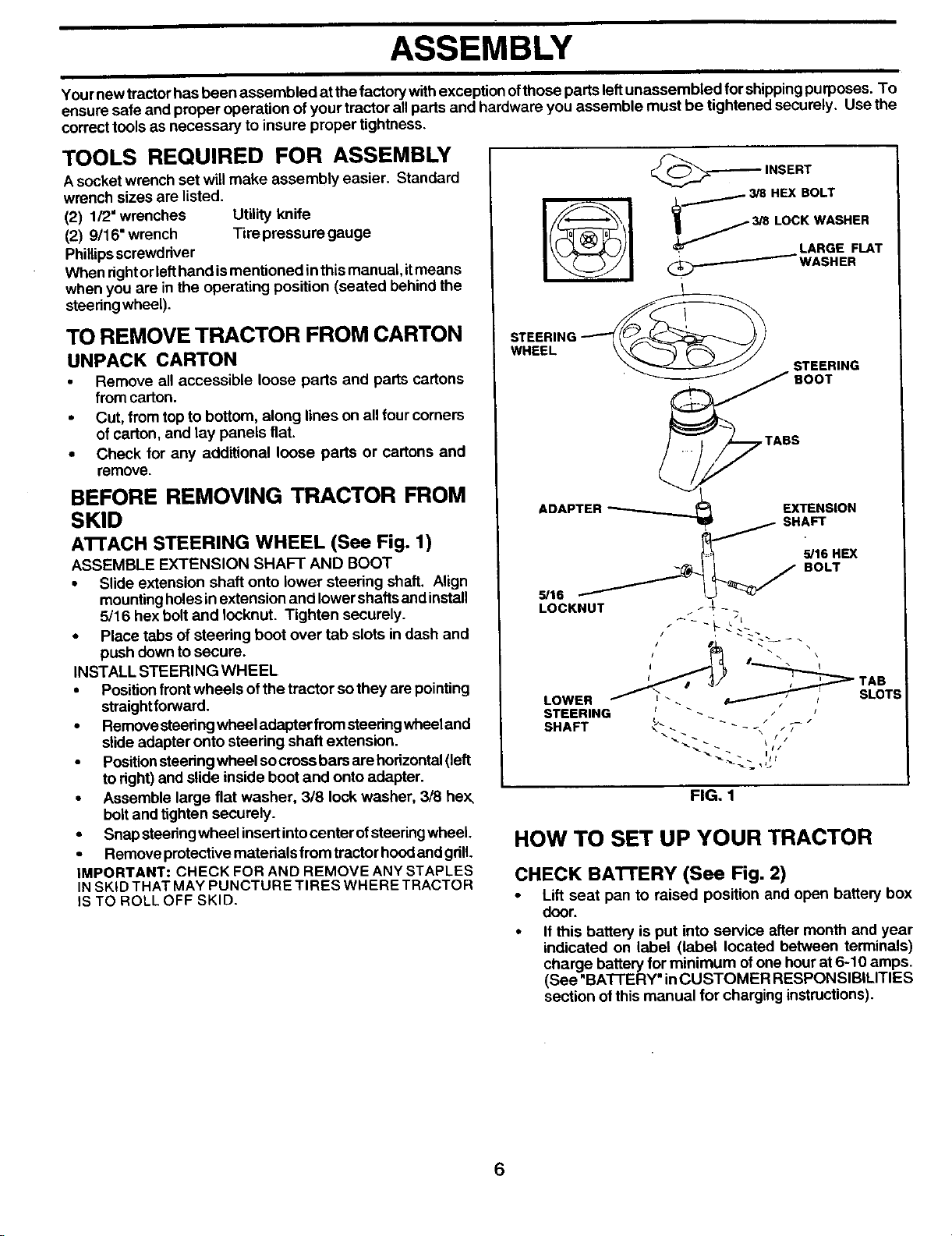
AI-rACH STEERING WHEEL (See Fig. 1)
ASSEMBLE EXTENSION SHAFT AND BOOT
• Slide extension shaft onto lower steering shaft. Align
mounting holes in extension and lower shafts and install
5/16 hex bolt and Iocknut. Tighten securely.
• Place tabs of steering boot over tab slots in dash and
push down to secure.
INSTALL STEERING WHEEL
• Position front wheels of the tractor so they are pointing
straightforward.
• Remove steedngwheel adapter fromsteedngwheeland
slide adapter onto steering shaft extension.
• Positionsteeringwheel socross bars are horizontal(left
to right) and slide inside boot and onto adapter.
• Assemble large flat washer, 318 lock washer, 318 hex,
boltand tighten securely.
• Snap steeringwheelinsert intocenter ofstseringwheel.
• Remove protective materials from tractor hood and gdlL
IMPORTANT: CHECK FOR AND REMOVE ANY STAPLES
INSKID THAT MAY PUNCTURE TIRES WHERE TRACTOR
IS TO ROLL OFF SKID.
,_-_ INSERT
• / 3/8 HEX BOLT
_ 3/8 LOCK WASHER
, LARGE FLAT
(_.._ WASHER
STEERING __
WHEEL
STEERING
'_ BOOT
.__TABS
ADAPTER _ EXTENSION
SHAFT
,OH X
S,'16 _ BOLT
LOCKNUT / J_- -
LOWER / _'. _ _' SLOT:
STEERING _ _ _ _
SHAFT _" - - _ --
FIG. 1
HOW TO SET UP YOUR TRACTOR
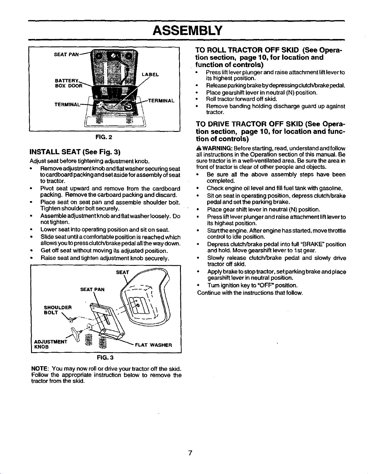
CHECK BA'FI'ERY (See Fig. 2)
• Lift seat pan to raised position and open battery box
door.
• If this battery is put into service after month and year
indicated on label (label located between terminals)
charge battery for minimum ofone hour at 6-10 amps.
(See "BA'I-I'ERY" inCUSTOMER RESPONSIBILITIES
section ofthis manual for charging instructions).
6
ASSEMBLY
BATTERY
BOX
LABEL
FIG. 2
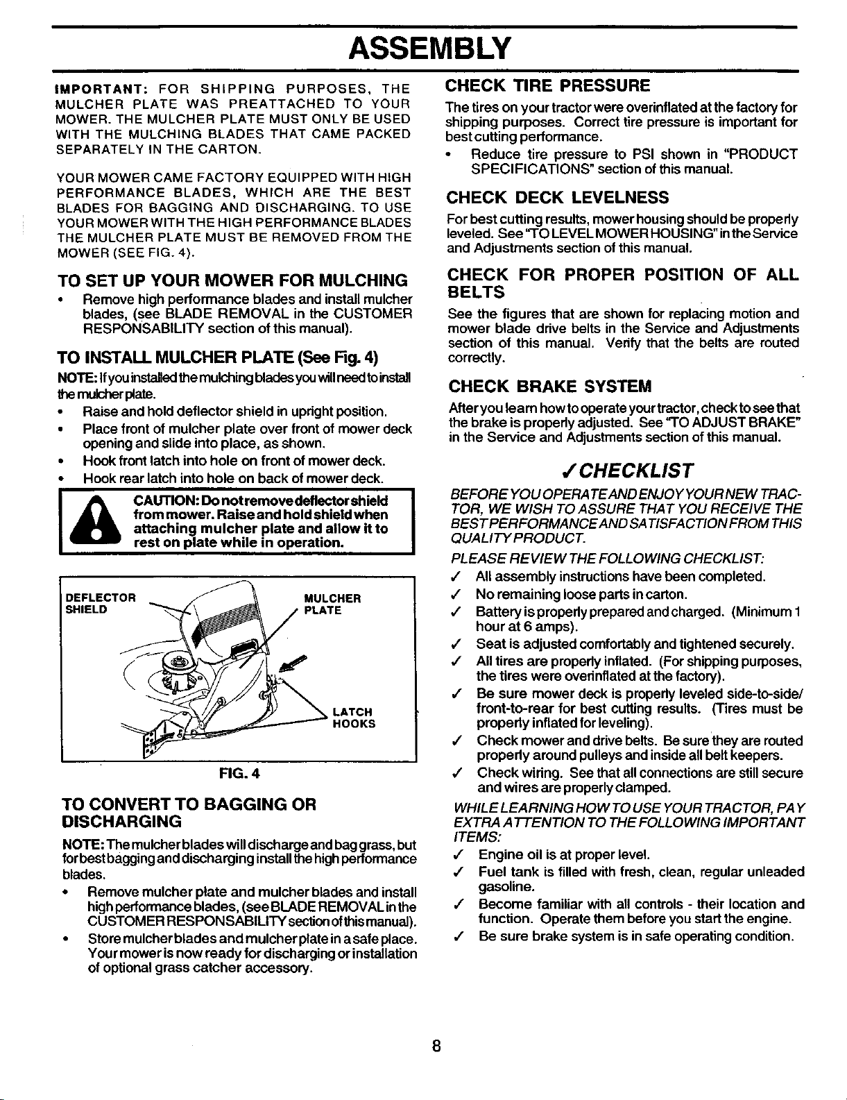
INSTALL SEAT (See Fig. 3)
Adjustseat before tighteningadjustment knob.
• Remove adjustment knoband fiatwasher securing seat
tocardboard packingand set aside forassembly ofseat
totractor.
• Pivot seat upward and remove from the cardboard
packing. Remove the carboard packing and discard.
• Place seat on seat pan and assemble shoulder bolt.
Tighten shoulder bolt securely.
• Assembleadjustmentknobandflatwasherloosely. Do
not tighten.
• Lower seat into operating position and sit on seat.
• Slide seat until a comfortable position is reached which
allows you to press clutch/brake pedal all the way down.
• Get oft seat without moving its adjusted position.
• Raise seat and tighten adjustment knob securely.
i
SHOULDER
BOLT _.__ .
ADJUSTMENT '_
KNOB
SEAT PAN SE_
i _ FLAT WASHER
FIG. 3
NOTE: You may now rollor driveyour tractor off the skid.
Follow the appropriate instruction below to remove the
tractor from the skid.
TO ROLL TRACTOR OFF SKID (See Opera-
tion section, page 10, for location and
function of controls)
• Press lift lever plunger and raise attachment lift lever to
its highest position.
• Releaseparking brake by depressing clutch/brake pedal.
• Place gearshift lever in neutral (N) position.
• Roll tractor forward off skid.
• Remove banding holding discharge guard up against
tractor.
TO DRIVE TRACTOR OFF SKID (See Opera-
tion section, page 10, for location and func-
tion of controls)
WARNING: Before starting, read, understand and follow
all instructionsin the Operation section of this manual. Be
sure tractor is in a well-ventilated area. Be sure the area in
front oftractor isclear of other people and objects.
• Be sure all the above assembly steps have been
completed.
• Check engine oillevel and fill fuel tank with gasoline.
• Siton seat in operating position, depress clutch/brake
pedal and set the parking brake.
• Place gear shift lever in neutral (N) position.
• Press liftlever plunger and raise attachment liftlever to
its highest position.
• Startthe engine. After engine hasstarted, movethrottle
controlto idle position.
• Depress clutch/brake pedal intofull "BRAKE" position
and hold. Move gearshift lever to 1st gear.
• Slowly release clutch/brake pedal and slowly drive
tractor off skid.
• Applybrake tostoptractor, set parking brake and place
gearshift lever in neutral position.
• Turn ignitionkey to"OFF" position.
Continue withthe instructionsthat follow.
7
ASSEMBLY
CHECK TIRE PRESSURE
IMPORTANT: FOR SHIPPING PURPOSES, THE
MULCHER PLATE WAS PREATTACHED TO YOUR
MOWER. THE MULCHER PLATE MUST ONLY BE USED
WITH THE MULCHING BLADES THAT CAME PACKED
SEPARATELY IN THE CARTON.
YOUR MOWER CAME FACTORY EQUIPPED WITH HIGH
PERFORMANCE BLADES, WHICH ARE THE BEST
BLADES FOR BAGGING AND DISCHARGING. TO USE
YOUR MOWER WITH THE HIGH PERFORMANCE BLADES
THE MULCHER PLATE MUST BE REMOVED FROM THE
MOWER (SEE FIG. 4).
TO SET UP YOUR MOWER FOR MULCHING
• Remove high performance blades and install mulcher
blades, (see BLADE REMOVAL in the CUSTOMER
RESPONSABILITY section of this manual).
TO INSTALL MULCHER PLATE (See Fig. 4)
NOTE: Ifyou installedthemulching bladesyouwillneedtoinstall
themulsher plate.
• Raise and hold deflector shield in upright position.
• Place front of mulcher plate over front of mower deck
opening and slide into place, as shown.
• Hook front latch into hole on front of mower deck.
• Hook rear latch into hole on back of mower deck.
I& AUTION: Do not remove deflector shield I
from mower. Raise and hold shield when
attaching mulcher plate and allow it to
rest on plate while in operation.
DEFLECTOR MULCHER
SHIELD PLATE
LATCH
HOOKS
FIG. 4
TO CONVERT TO BAGGING OR
DISCHARGING
NOTE: The mulcherblades willdischarge and baggrass,but
forbest baggingand discharging installthe highperformance
blades.
• Remove mulcher plate and mulcher blades and install
highperformance blades, (see BLADE REMOVAL inthe
CUSTOMER RESPONSABILITY secl_onofthis manual).
• Store mulcher blades and mulcher plate ina safe place.
Your mower isnow ready for discharging or installation
of optional grass catcher accessory.
The tires on your tractor were overinflated at the factory for
shipping purposes. Correct tire pressure is important for
best cutting performance.
• Reduce tire pressure to PSI shown in "PRODUCT
SPECl FICATIONS" section of this manual.
CHECK DECK LEVELNESS
For best cutting results, mower housingshouldbe propedy
leveled. See "TO LEVEL MOWER HOUSING" inthe Service
and Adjustments section of this manual.
CHECK FOR PROPER POSITION OF ALL
BELTS
See the figures that are shown for replacing motion and
mower blade ddve belts in the Service and Adjustments
section of this manual. Verify that the belts are routed
correctly.
CHECK BRAKE SYSTEM
Afteryou learn howtooperate yourtractor, checktosee that
the brake is prepedy adjusted. See "TO ADJUST BRAKE"
in the Service and Adjustments sectionof this manual.
/ CHECKLIST
BEFORE YOU OPERA TEAND ENJOY YOUR NEW TRAC-
TOR, WE WISH TO ASSURE THAT YOU RECEIVE THE
BESTPERFORMANCEAND SA TISFACTION FROM THIS
QUALITY PRODUCT.
PLEASE REVIEW THE FOLLOWING CHECKLIST:
,/ Allassembly instructionshave been completed.
4 No remaining loose parts incarton.
•/ Battery ispropedy prepared andcharged. (Minimum 1
hour at 6 amps).
4" Seat is adjusted comfortably and tightened securely.
•/ All tires are propedy inflated. (For shippingpurposes,
the tires were ovednflated at the factory).
,/ Be sure mower deck is propedy leveled side-to-side/
front-to-rear for best cuffing results. (Tires must be
properly inflated for leveling).
,/ Check mower and drivebelts. Be surethey are routed
propedy around pulleys and insideall belt keepers.
,/ Check widng. See that all connections are stillsecure
and wires are properlyclamped.
WHILE LEARNING HOW TO USE YOUR TRACTOR, PAY
EXTRA ATTENTION TO THE FOLLOWING IMPORTANT
ITEMS:
,f Engine oil is at proper level.
,/ Fuel tank is filled with fresh, clean, regular unleaded
gasoline.
,/ Become familiar with all controls - their location and
function. Operate them before you start the engine.
J Be sure brake system is in safe operating condition.
8
OPERATION
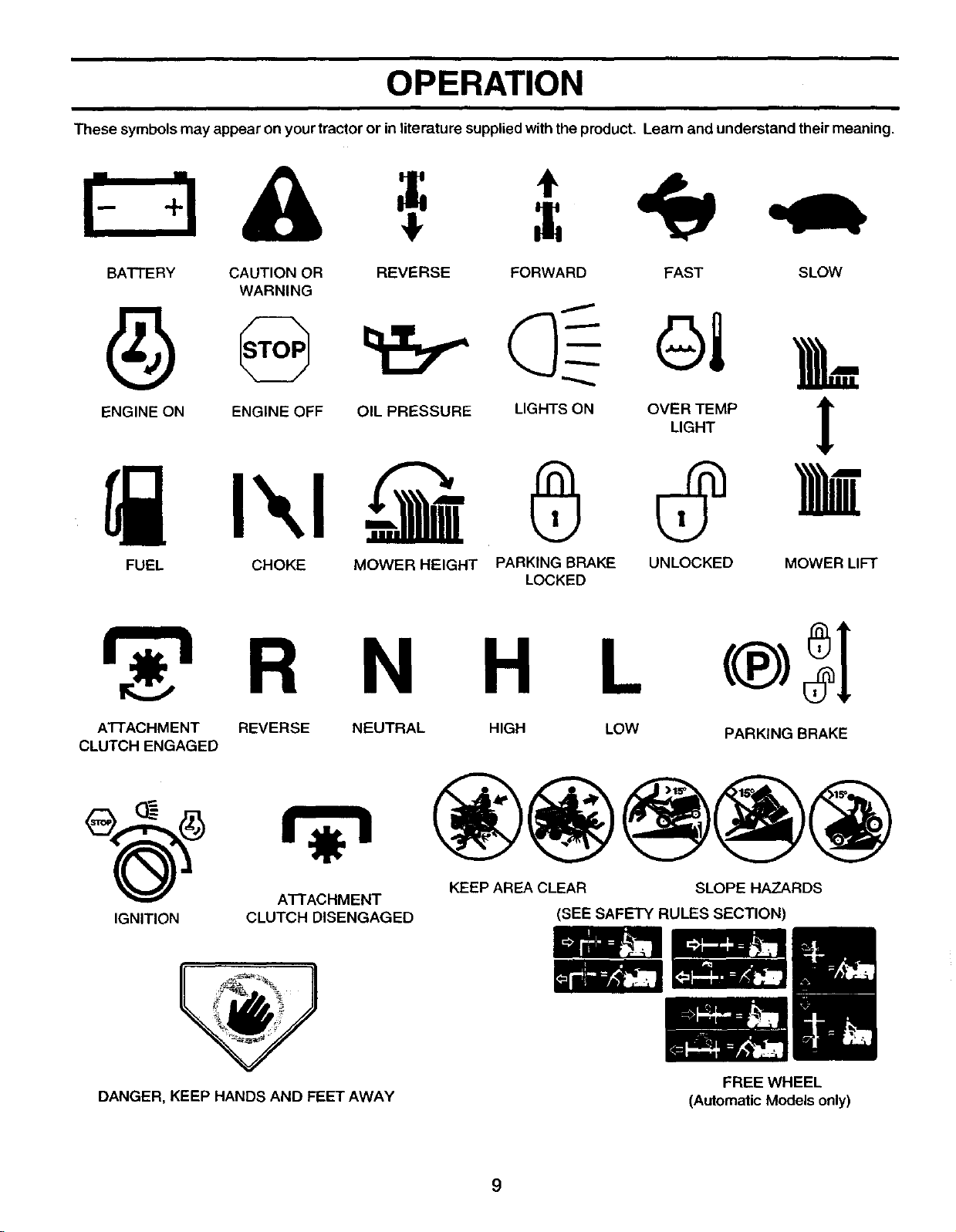
These symbols may appear on yourtractor or in literature supplied with the product. Learn and understand their meaning.
I- qA
BATTERY CAUTION OR REVERSE FORWARD FAST SLOW
WARNING
,L
ENGINE ON ENGINE OFF OIL PRESSURE LIGHTS ON OVER TEMP lr
LIGHT
!
FUEL CHOKE MOWER HEIGHT PARKING BRAKE UNLOCKED MOWER LIFT
LOCKED
r -i R N H L
ATTACHMENT REVERSE
CLUTCH ENGAGED
NEUTRAL HIGH LOW
PARKING BRAKE
KEEP AREA CLEAR SLOPE HAZARDS
ATTACHMENT
IGNITION CLUTCH DISENGAGED (SEE SAFETY RULES SECTION)
DANGER, KEEP HANDS AND FEET AWAY
FREE WHEEL
(Automatic Models only)
9
OPERATION
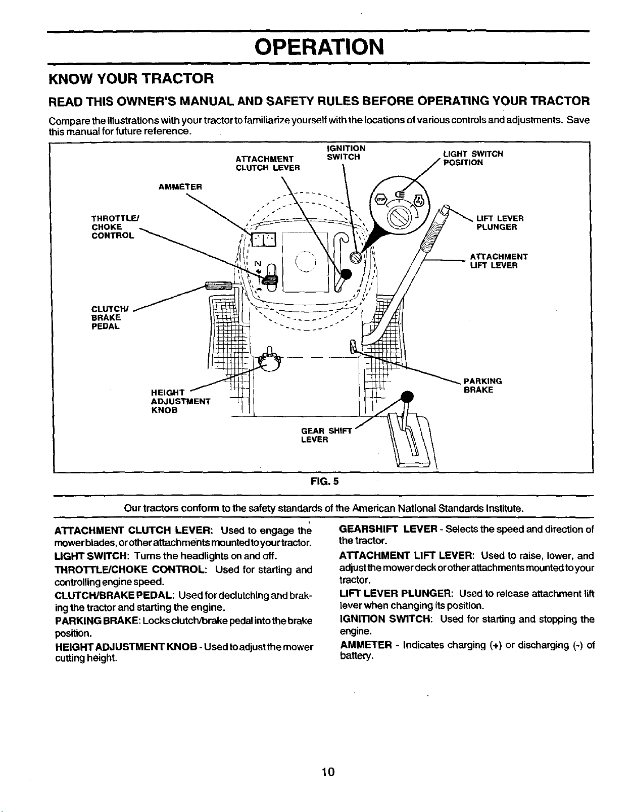
KNOW YOUR TRACTOR
READ THIS OWNER'S MANUAL AND SAFETY RULES BEFORE OPERATING YOUR TRACTOR
Compare theillustrations with your tractortofamiliarize yourself withthe locations ofvarious controlsand adjustments. Save
thismanual for future reference.
ATTACHMENT
CLUTCH LEVER
IGNITION
SWITCH LIGHT SWITCH
AMMETER
THROTTL_ LIFT LEVER
CHOKE PLUNGER
CONTROL
ATTACHMENT
UFTLEVER
HEIGHT
ADJUSTMENT
KNOB
GEAR SHIFT
LEVER
PARKING
BRAKE
FIG. 5
Our tractors conform to the safety standards ofthe American National Standards Institute.
ATTACHMENT CLUTCH LEVER: Used to engage the
mowerblades, orotherattachments mountedtoyourtractor.
UGHT SWITCH: Turns the headlights on and off.
THROTTLE/CHOKE CONTROL: Used for starting and
controllingengine speed.
CLUTCH/BRAKE PEDAL: Used for declutchingand brak-
ingthe tractor and starting the engine.
PARKING BRAKE: Locks clutch/brake pedalintothe brake
position.
HEIGHT ADJUSTMENT KNOB - Used toadjustthe mower
cutting height.
GEARSHIFT LEVER - Selects the speed and direction of
the tractor.
ATTACHMENT LIFT LEVER: Used to raise, lower, and
adjustthe mower deck orotherattachments mountedtoyour
tractor.
LIFT LEVER PLUNGER: Used to release attachment lift
lever when changing itsposition.
IGNITION SWITCH: Used for starting and stopping the
engine.
AMMETER - Indicates charging (+) or discharging (-) of
battery.
10
OPERATION
I
The operation ofany tractor can result inforeign objects thrown into the eyes, which can
result in severe eye damage. Always wear safety glasses or eye shields while operating
your tractor or performing any adjustments or repairs. We recommend a wide vision
safety mask over spectacles or standard safety glasses.
I
HOW TO USE YOUR TRACTOR
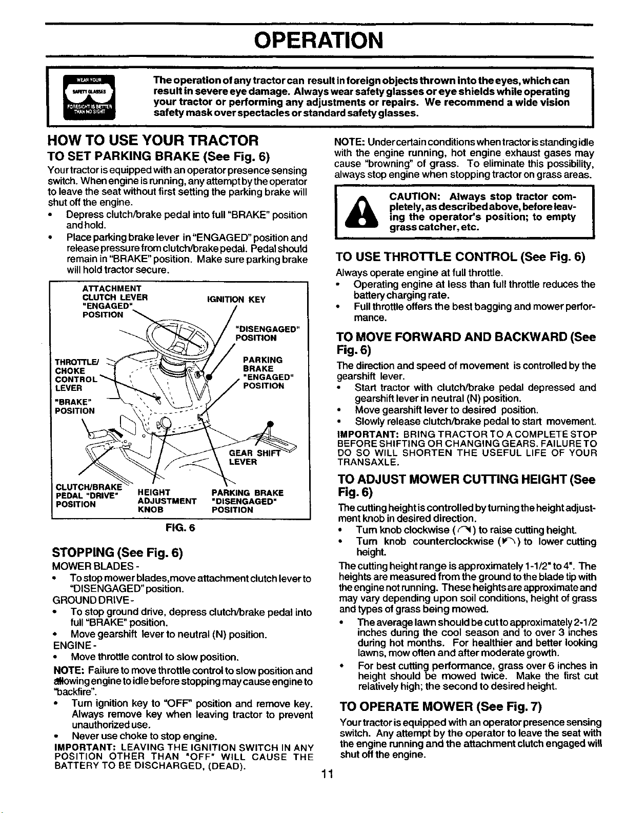
TO SET PARKING BRAKE (See Fig. 6)
Yourtractorisequipped with an operator presence sensing
switch.When engine isrunning, any attemptbytheoperator
to leave the seat without first setting the parking brake will
shut offthe engine.
• Depress clutch/brake pedal intofull "BRAKE" position
and hold.
• Place parkingbrake lever in"ENGAGED" position and
release pressurefromclutch/brake pedal Pedal should
remain in"BRAKE" position. Make sure parking brake
willholdtractor secure.
I
ATTACHMENT
CLUTCH LEVER
"ENGAGED"
POSITION
IGNITION KEY
"DISENGAGED"
POSITION
THRO'n'LE/
PARKING
BRAKE
"ENGAGED"
POSITION
LEVER
PEDAL "DRIVE" HEIGHT PARKING BRAKE
POSITION ADJUSTMENT "DISENGAGED"
KNOB POSITION
FIG. 6
STOPPING (See Fig. 6)
MOWER BLADES -
• To stop mower blades,move attachment clutch lever to
"DISENGAGED" position.
GROUND DRIVE-
• To stop ground drive, depress clutch/brake pedal into
full "BRAKE" position.
• Move gearshift lever to neutral (N) position.
ENGINE -
• Move throttle controlto slow position.
NOTE: Failureto move throttle controlto slow positionand
eNowingengine toidlebefore stopping may cause engine to
"backfire".
• Turn ignition key to "OFF" position and remove key.
Always remove key when leaving tractor to prevent
unauthorized use.
Never use choke to stop engine.
IMPORTANT: LEAVING THE IGNITION SWITCH IN ANY
POSITION OTHER THAN "OFF" WILL CAUSE THE
BATTERY TO BE DISCHARGED, (DEAD).
NOTE: Under certain conditions when tractor isstanding idle
with the engine running, hot engine exhaust gases may
cause "browning" of grass. To eliminate this possibility,
always stop engine when stopping tractor on grass areas.
&
|
CAUTION: Always stop tractor com- |
pletety, as described above, before leav-
I
ing the operator's position; to empty
grass catcher, etc.
TO USE THRO'n'LE CONTROL (See Fig. 6)
Always operate engine at fullthrottle.
Operating engine at less than full throttle reduces the
battery charging rate.
• Full throttle offers the best bagging and mower perfor-
mance.
TO MOVE FORWARD AND BACKWARD (See
Fig. 6)
The direction and speed of movement is controlledby the
gearshift lever.
• Start tractor with clutch/brake pedal depressed and
gearshift lever in neutral (N) position.
• Move gearehiff lever to desired position.
Slowly release clutch/brake pedal to start movement.
IMPORTANT: BRING TRACTOR TO A COMPLETE STOP
BEFORE SHIFTING OR CHANGING GEARS. FAILURE TO
DO SO WILL SHORTEN THE USEFUL LIFE OF YOUR
TRANSAXLE.
TO ADJUST MOWER CU'I-rlNG HEIGHT (See
Fig. 6)
The cuttingheightis controlled byturningthe heightadjust-
ment knob in desired direction.
• Turn knobclockwise ((-_) to raise cuttingheight.
• Turn knob counterclockwise (1_-_)to lower cutting
height.
The cutting height range is approximately 1-1/2" to4". The
heights are measured from the ground totheblade tipwith
theengine notrunning. These heights areapproximateand
may vary depending upon soil conditions, height of grass
and types ofgrass being mowed.
• The average lawn should be cutto approximately2-1/2
inches during the cool season and to over 3 inches
during hot months. For healthier and better looking
lawns, mow often and after moderate growth.
• For best cutting performance, grass over S inches in
height should be mowed twice. Make the first cut
relatively high; the second to desired height.
TO OPERATE MOWER (See Fig. 7)
Yourtractor isequipped with an operator presence sensing
switch. Any attempt by the operator to leave the seat with
the engine running and the attachment clutchengaged will
shut off the engine.
11
OPERATION
• Select desired height ofcut.
• Lower mower with attachment lift control.
• Start mower blades by engaging attachment clutch
control
• TO STOP MOWER BLADES - disengage attachment
clutch control.
A
CAUTION: Do not operate the mower
without either the entire grass catcher,
on mowers so equipped, or the dis-
charge guard in place.
ATTACHMENT
CLUTCH LEVER -_
"DISENGAGED = -->_
POSITION
'ENGAGED" POSITION
ATTACHMENT
LIFT LEVER
HIGH
i',! _ POSITION
POSITION
7;
DEFLECTOR
FIG. 7
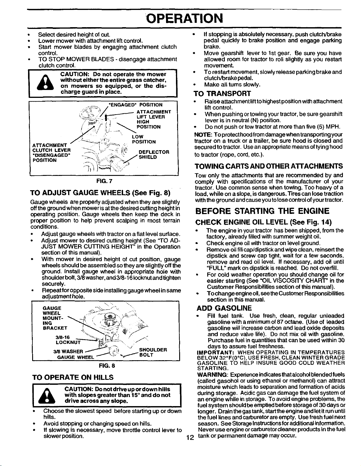
TO ADJUST GAUGE WHEELS (See Fig. 8)
Gauge wheels are properlyadjusted when they are slightly
offthe ground when mower isat thedesired cuttingheight in
operating position. Gauge wheels then keep the deck in
proper position to help prevent scalping in most terrain
conditions.
• Adjust gauge wheels with tractor on a flat level surface.
• Adjust mower to desired cutting height (See "1"OAD-
JUST MOWER CU'I-FING HEIGHT" in the Operation
section of this manual).
• With mower in desired height of cut position, gauge
wheels should be assembled so they are slightlyoff the
ground. Install gauge wheel in appropdate hole with
shoulder bolt, 3/8 washer, and 3/8-16 Iocknut and tighten
securely.
• Repeat for opposite side installing gauge wheel in same
adjustment hole.
GAUGE -- "'_
WHEEL . .,:_,\
MOUNT-
ING
BRACKET
3/8-16
LOCKNUT J:_
3/S WASHER SHOULDER
GAUGE WHEEL
FIG. 8
TO OPERATE ON HILLS
I & CAUTION: Donotdriveupordownhills I
with slopes greater than 15° and do not
drive across any slope.
• Choose the slowest speed before starting up or down
hills.
• Avoid stopping or changing speed on hills.
• If slowing is necessary, move throttle control lever to
slower position.
• If stopping is absolutely necessary, push clutch/brake
pedal quickly to brake position and engage parking
brake.
• Move gearshift lever to 1st gear. Be sure you have
allowed room for tractor to roll slightly as you restart
movement.
• To restart movement, slowly release parking brake and
clutch/brake pedal.
• Make all turns slowly.
TO TRANSPORT
• Raise attachment lift to highest position with attachment
lift control.
• When pushing ortowing your tractor, be sure gearshift
lever is in neutral (N) position.
• Do not push or tow tractor at more than five (5) MPH.
NOTE: To protect hood from damage when transporting your
tractor on a truck or a trailer, be sure hood is closed and
secured to tractor. Use an appropriate means of tyinghood
to tractor (rope, cord, etc.).
TOWING CARTS AND OTHER ATrACHMENTS
Tow only the attachments that are recommended by and
comply with specifications of the manufacturer of your
tractor. Use common sense when towing. Too heavy of a
load, while on a slope, is dangerous. Tires can lose traction
with the ground and cause you to lose control of you rtractor.
BEFORE STARTING THE ENGINE
12
CHECK ENGINE OIL LEVEL (See Fig. 14)
• The engine in yourtractor has been shipped, from the
factory, already filled withsummer weight oil.
• Check engine oilwithtractoron level ground.
• Remove oilfillcap/dipstickand wipe clean, reinsert the
dipstick and screw cap tight, wait for a few seconds,
remove and read oil level. If necessary, add oil until
"FULL" mark ondipstick isreached. Do not overfill.
, For cold weather operation you should change oil for
easier starting (See "OIL VISCOSITY CHART" in the
Customer Responsibilitiessection ofthis manual).
• To change engineoil,seetheCustomer Reaponsibilities
section in this manual.
ADD GASOLINE
• Fill fuel tank. Use fresh, clean, regular unleaded
gasoline with a minimum of87 octane. (Use of leaded
gasoline willincrease carbon and lead oxide deposits
and reduce valve life). Do not mix oil with gasoline.
Purchase fuel in quantities that can be used within 30
days to assure fuel freshness.
IMPORTANT: WHEN OPERATING IN TEMPERATURES
BELOW 32°F(0°C), USE FRESH, CLEAN WINTER GRADE
GASOLINE TO HELP INSURE GOOD COLD WEATHER
STARTING.
WARNING: Experience indicatesthatalcoholblendedfuels
(called gasohol or using ethanol or methanol) can attract
moisture Which leads to separation and formation of acids
during storage. Acidic gas can damage the fuel system of
an engine while in storage. To avoid engine problems, the
fuel system should be emptied before storage of 30 days or
longer. Drain the gastank, start the engine and let it run until
the fuel lines and carburetorare empty. Use fresh fuel next
season. See Storage Instructionsfor additionalinformation.
Never use engine orcarburetor cleaner products in the fuel
tank or permanent damage may occur.
OPERATION
I
&
CAUTION: Fill to bottom of gas tank J "
filler neck. Do not overfill. Wipe off any
I
spilled oil or fuel. Do not store, spill or
use gasoline near an open flame. •
TO START ENGINE (See Fig. 6)
When startingthe engine forthe firettime or iftheengine has
run out of fuel, itwill take extra cranking time to move fuel
from the tank to the engine.
• Sit on seat in operating position, depress clutch/brake
pedal and set parking brake.
• Place gear shift lever in neutral (N) position.
• Move attachment clutch to "DISENGAGED" position.
• Move throttle control to choke gkl) position.
NOTE: Before starting, read the warm and cold starting
procedures below.
• Insert key into ignition and turn key clockwise to
"START' position and release key as soon as engine
starts. Do not run starter continuously for more than
fifteen seconds per minute. If the engine does not start
after several attempts, move throttle control to fast
position, wait a few minutes and try again. If engine still
does not start, move the throttle control back to the
choke (1\1)position and retry.
WARM WEATHER STARTING (50 ° F and above)
When engine starts, move the throttle control tothe fast
position.
• The attachments and ground drive can now be used. If
the engine does not accept the load, restart the engine
and allow it to warm up for one minute using the choke
as described above.
COLD WEATHER STARTING ( 50 ° F and below)
• When engine starts, allow engine to run withthe throttle
control in the choke (1\1)position until the engine runs
roughly, then move throttle control to fast position. This
may require an engine warm-up period from several
seconds to several minutes, depending on the tempera-
ture.
• The attachments can also be used during the engine
warm-up pedod.
NOTE: If at a high altitude (above 3000 feet) or in cold
temperatures (below 32 F) the carburetor fuel mixture may
need to be adjusted for best engine performance. See "TO
ADJUST CARBURETOR" in the Service and Adjustments
section of this manual.
MOWING TIPS
Mower should be properly leveled for best mowing
performance. See "TO LEVEL MOWER HOUSING" in
the Service and Adjustments section ofthis manual,
The lefthand sideofmower shouldbe usedfortrimming.
Drive sothat clippingsare discharged ontotheareathat
has been cut. Have the cut area to the right of the
machine. This will result in a more even distributionof
clippings and more uniform cutting.
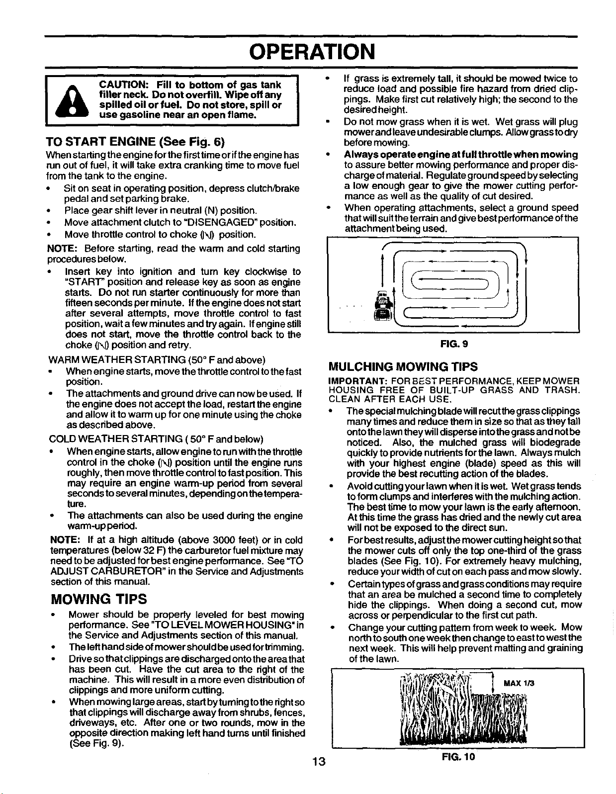
When mowing largeareas, startbytuming totherightso
that clippings willdischarge away from shrubs,fences,
driveways, etc. After one or two rounds, mew in the
opposite direction making left hand turns untilfinished
(See Fig. 9).
If grass isextremely tall, it should be mowed twice to
reduce load and possible fire hazard from dried clip-
pings. Make first cut relatively high; the second to the
desired height.
Do not mow grass when it iswet. Wet grass will plug
mower and leave undesirableclumps. Allowgrass to dry
before mowing.
Always operate engine at full throttle when mowing
to assure better mowing performance and proper dis-
charge ofmaterial. Regulate groundspeed byselecting
a low enough gear to give the mower cutting perfor-
mance as well as the quality ofcut desired.
When operating attachments, select a ground speed
thatwillsuittheterrain and give best performance ofthe
attachment being used.
f
T
(
.i
FIG. 9
MULCHING MOWING TIPS
IMPORTANT: FOR BEST PERFORMANCE, KEEP MOWER
HOUSING FREE OF BUILT-UP GRASS AND TRASH.
CLEAN AFTER EACH USE.
• The special mulchingbladewillrecutthe grassclippings
many times and reduce them in size sothatas they fall
ontothe lawntheywilldisperse intothegrassand notbe
noticed. Also, the mulched grass will biodegrade
quickly to providenutrientsfor the lawn. Always mulch
with your highest engine (blade) speed as this will
provide the best recutting action ofthe blades.
• Avoid cuffingyour lawn when itiswet. Wet grass tends
toform clumpsand interferes with the mulchingaction.
The best time to mow your lawn is the eady afternoon.
Atthis timethe grass has dried and thenewly cut area
will not be exposed to the direct sun.
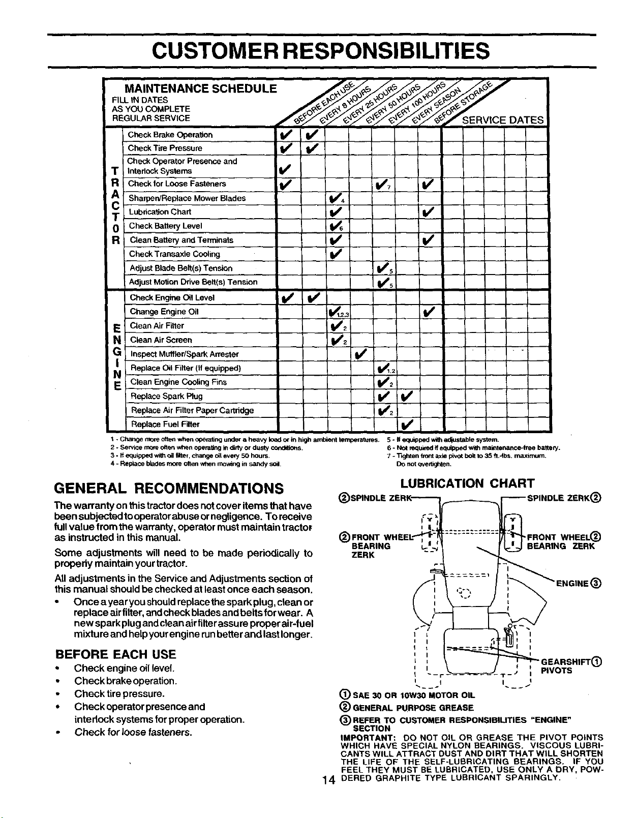
• For best results,adjust the mower cuttingheight sothat
the mower cuts off only the top one-third of the grass
blades (See Fig. 10). For extremely heavy mulching,
reduce yourwidthofcut on each passand mow slowly.
• Certain typesofgrass and grass conditionsmay require
that an area be mulched a second time to completely
hide the clippings. When doing a second cut, mow
across or perpendicular to the first cutpath.
• Change yourcutting pattern from week to week. Mow
northtosouthone week then change toeastto westthe
next week. This willhelp prevent mattingand graining
ofthe lawn.
I! _ '. ,,,tI l
,'.! :
13 FIG. 10
CUSTOMER RESPONSIBILITIES
FILL IN DATES
AS YOU COMPLETE , _ _'_ 9,_
Y_,_._/'e_" SERVICE DATES
C ckBr.eo.ra.nW
Check Tire Pressure
Check Operator Presence and
T !Interlock Systems I_
R!C"e for Loose Fasteners I_ I_? V _
A
Sharpen/Replace Mower Blades I_.
C Lubrication Chart V _
O Check Battery Level
Clean Battery and Terminals !_
Check Transaxle Cooling V'
Adjust Blade Bait(s)Tension VPs
Adjust Motion Drive Belt(s) Tension I I_s [
Check Engine Oil Level i I_ ll_
Change Engine Oil _i 3
Clean Air Filter
Clean Air Screen
Inspect Muffler/Spark An'ester
Reptace Oil Filter (if equipped) li_12
Clean Engine Cooling Fins i_ 2
Replace Spark Plug Ik_
Replace Air Filter Paper Cartridge 11_2
Replace Fuel Filter li/
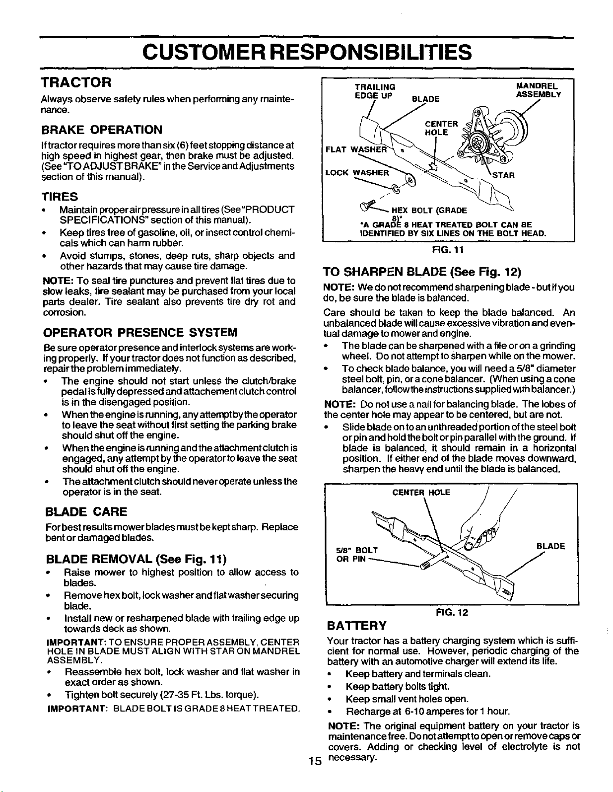
1 -Changemoreonenwhenoperalingunderaheavyioadorinhighambientte_ms. 5-#eq_pt0edv._hadiustablesystem.
2 - Service rnomoften when operatingin didy or dusty cold,ions. 6 - NOtrequited if equipped with maintenance-free batte_.
3 - If equipped withOilfilter, change Oileve_ 50 hours. 7 - T_hten fiont axle pivot boltto 35 ft.4bs, maximum.
4 - Replace bk_les more often when mow_g in sandy soil. DOnot overl_hten.
GENERAL RECOMMENDATIONS
The warranty on thistractordoes not cover items that have
been subjected tooperatorabuse ornegligence. To receive
fullvalue from the warranty, operator must maintain tracto_
as instructed in this manual.
Some adjustments will need to be made periodically to
propedy maintain yourtractor.
Alladjustments in the Service and Adjustments section of
this manual shouldbe checked at leastonce each season.
• Once a yearyou should replacethe spark plug,clean or
replace eir filter,andcheck bladesand belts for wear. A
new spark plug andclean airfilterassure proper air-fuel
mixture and helpyourengine runbetter and lastlonger.
BEFORE EACH USE
• Check engine oillevel.
• Check brake operation.
• Check tirepressure.
• Check operator presence and
interlock systems for proper operation.
Check for loose fasteners.
(_)SPINDLE
(_ FRONT
BEARING
ZERK
LUBRICATION CHART
•FRONT WHEEL(_
L- BEARING ZERK
GEARSHIFT_)
"r- ) PIVOTSI
I I
1_ SAE 30 OR 10W30 MOTOR OIL
(_) GENERAL PURPOSE GREASE
(_)REFER TO CUSTOMER
RESPONSIBILITIES
"ENGINE"
SECTION
IMPORTANT: DO NOT OIL OR GREASE THE PIVOT POINTS
WHICH HAVE SPECIAL NYLON BEARINGS. VISCOUS LUBRI-
CANTS WILL ATTRACT DUST AND DIRT THAT WILL SHORTEN
THE LIFE OF THE SELF-LUBRICATING BEARINGS. IF YOU
FEEL THEY MUST BE LUBRICATED, USE ONLY A DRY, POW-
14 DERED GRAPHITE TYPE LUBRICANT SPARINGLY.
CUSTOMER RESPONSIBILITIES
TRACTOR
Always observe safety rules when performingany mainte-
nance.
BRAKE OPERATION
Iftractor requires more than six (6) feet stoppingdistance at
high speed in highest gear, then brake must be adjusted.
(See =TOADJUST BRAKE" inthe Service andAdjustments
section of this manual).
TIRES
• Maintainproperairpressureinalltires(See=PRODUCT
SPECIFICATIONS" section ofthis manual).
• Keep tires free ofgasoline, oil, or insectcontrolchemi-
cals which can harm rubber.
• Avoid stumps, stones, deep ruts, sharp objects and
other hazards that may cause tire damage.
NOTE: To seal tire punctures and prevent flat tires due to
slow leaks, tire sealant may be purchased from your local
parts dealer. Tire sealant also prevents tire dry rot and
corrosion.
OPERATOR PRESENCE SYSTEM
Besure operator presence and interlocksystems are work-
ing properly. Ifyour tractor does not function as described,
repairthe problem immediately.
• The engine should not start unless the clutch/brake
pedal isfully depressed and attachement clutchcontrol
is in the disengaged position.
• When theengine isrunning, any attemptbythe operator
to leave the seat without first settingthe parking brake
should shut offthe engine.
• When theengine isrunning and theattachment clutchis
engaged, any attempt bythe operatortoleave the seat
should shut off the engine.
• The attachment clutch shouldneveroperate unless the
operator is in the seat.
BLADE CARE
Forbest resultsmower blades must bekeptsharp. Replace
bentor damaged blades.
BLADE REMOVAL (See Fig. 11)
• Raise mower to highest position to allow access to
blades.
• Remove hex bolt, lockwasher and fiatwasher securing
blade.
• Install new or resharpened blade with trailingedge up
towards deck as shown.
IMPORTANT: TO ENSURE PROPER ASSEMBLY. CENTER
HOLE IN BLADE MUST ALIGN WITH STAR ON MANDREL
ASSEMBLY.
• Reassemble hex bolt, lock washer and flat washer in
exact order as shown.
• Tighten bolt securely (27-35 Ft. Lbs. torque).
IMPORTANT: BLADE BOLT IS GRADE 8 HEAT TREATED.
TRAILING MANDREL
EDGE UP BLADE ASSEMBLY
FLAT
LOCK WASHER
(_"-- HEX BOLT (GRADE
8"1'
*A GRADE 8 HEAT TREATED BOLT CAN BE
IDENTIFIED BY SIX LINES ON THE BOLT HEAD.
FIG. 11
TO SHARPEN BLADE (See Fig. 12)
NOTE: We do not recommendsharpening blade - butifyou
do, be sure the blade isbalanced,
Care should be taken to keep the blade balanced. An
unbalanced blade willcause excessive vibrationand even-
tual damage tomower and engine.
• The blade can besharpened with a file or on a grinding
wheel. Do not attempttosharpen while on the mower.
• To check blade balance, you willneed a 5/8" diameter
steel bolt, pin, ora cone balancer. (When using a cone
balancer, follow theinstructionssuppliedwithbalancer.)
NOTE: Do not usea nailfor balancing blade. The lobes of
the center hole may appear to be centered, but are not.
• Slide blade ontoan untbreaded portion ofthe steel bolt
or pinand holdtheboltor pinparallel withthe ground. If
blade is balanced, it should remain in a horizontal
position. If either end of the blade moves downward,
sharpen the heavy end until the blade isbalanced.
15
CENTER HOLE / /
us.SOL 'ADE
OR
FIG. 12
BATTERY
Your tractor has a battery charging system which is suffi-
cient for normal use. However, periodic charging of the
battery with an automotive charger willextend its life.
Keep battery and terminals clean.
• Keep battery boltstight.
• Keep small vent holes open.
• Recharge at 6-10 amperes for I hour.
NOTE: The original equipment battery on your tractor is
maintenance free. Donotattempttoopen or remove caps or
covers. Adding or checking level of electrolyte is not
necessary.
CUSTOMER RESPONSIBILITIES
TO CLEAN BATI'ERY AND TERMINALS
Corrosionand dirt onthe battery and terminals can cause the
battery to "leak" power.
• Open battery box door.
Disconnect BLACKbatterycable first then RED battery
cable and remove battery from tractor.
• Rinse the battery with plain water and dry.
• Clean terminals and battery cable ends with wire brush
until bright.
Coat terminals with grease or petroleum jelly.
Reinstall battery (See "REPLACING BATTERY" in the
Service and Adjustment section of this manual).
V-BELTS
Check V-belts fordeteriorationand wear after 100 hours and
replace if necessary. The belts are not adjustable. Replace
belts ifthey begin to slipfrom wear.
TRANSAXLE COOLING
Keep transaxle freefrombuild-up ofdirtand chaff which can
restrictcooling.
• Remove oil fill cap/dipstick. Be careful notto allow dirt
to enter the engine when changing oil.
• Remove drain plug.
• After oil has drained completely, replace oil drain plug
and tighten securely.
• Refill engine with oil through oil fill dipstick tube. Pour
slowly. Do not overfill. For approximate capacity see
"PRODUCT SPECIFICATIONS" section ofthis manual.
Use gauge on oil fill cap/dipstick for checking level. Be
sure dipstick cap is tightened securely for accurate
reading. Keep oil at "FULL" line on dipstick.
___ OIL FILL
CAP/DIPSTICK
_._ OIL DRAIN PLUG
ENGINE
FIG. 14
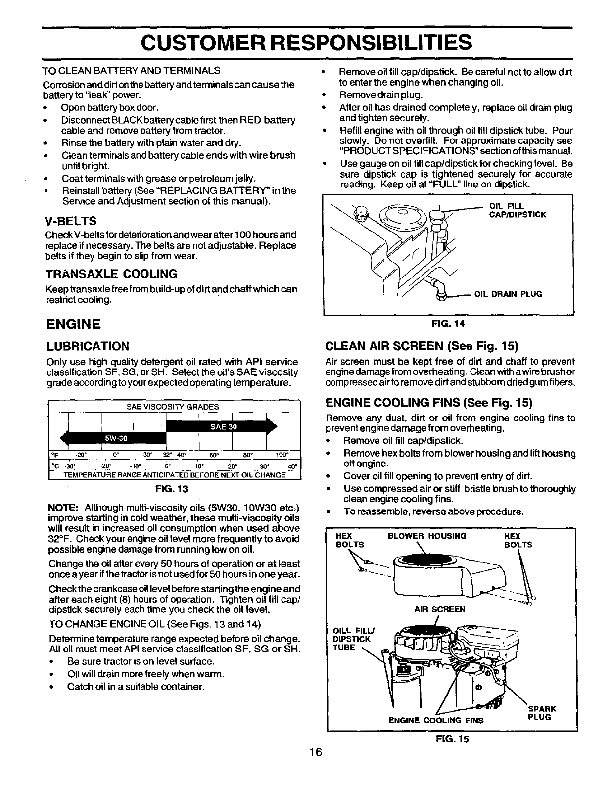
LUBRICATION
Only use high quality detergent oil rated with API service
classification SF, SG, or SH. Select the oil's SAE viscosity
grade according toyour expected operating temperature.
SAE VISCOSITY GRADES
0_ 30° 32 ° 40" 60 _
-3o- -2o, -,o" Do too 20" 30"
TEMPERATURE RANGE ANTICIPATED BEFORE NEXT OIL CHANGE
FIG. 13
NOTE: Although multi-viscosity oils (5W30, 10W30 etc:)
improve starting incoldweather, these multi-viscosity oils
will result in increased oilconsumption when used above
32°F. Check your engine oil level more frequently to avoid
possible engine damage from running low on oil.
Change the oilafter every 50 hours of operation or at least
once a year ifthe tractorisnot used for 50 hours in one year.
Check the crankcase oillevel before startingthe engine and
after each eight (8) hours of operation, Tighten oil fill cap/
dipstick securely each time you check the oil level.
TO CHANGE ENGINE OIL (See Figs. 13 and 14)
Determine temperature range expected before oilchange.
All oil must meet API service classification SF, SG or SH.
• Be sure tractor ison level surface.
• Oil willdrain more freely when warm.
• Catch oil in a suitable container.
CLEAN AIR SCREEN (See Fig. 15)
Air screen must be kept free of dirt and chaff to prevent
engine damage fromoverheating. Clean witha wirebrush or
comp reseed airto remove dirt and stubborn dried gum fibers,
ENGINE COOLING FINS (See Fig. 15)
Remove any dust, dirt or oil from engine cooling fins to
preventengine damage from overheating,
• Remove oil fillcap/dipstick.
• Remove hexboltsfrom blower housing and lifthousing
offengine.
• Cover oilfillopening to prevent entry of dirt.
• Use compressed air or stiff bristle brush tothoroughly
clean engine cooling fins.
• To reassemble, reverse above procedure.
HEX BLOWER HOUSING HEX
BOLTS BOLTS
AIR SCREEN
OILL FILL/
DIPSTICK
TUBE
ENGINE COOLING FINS
SPARK
PLUG
FIG. 15
16
CUSTOMER RESPONSIBILITIES
MUFFLER
ENGINE OIL FILTER
Replace the engine oilfilter every season orevery other oil
change ifthetractor isused more than 100 hoursinone year.
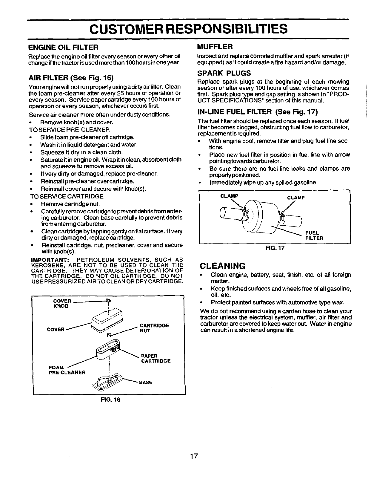
AIR ALTER (See Fig. 16)
Your engine willnot runpropedy usinga dirtyairfilter. Clean
the foam pre-cleaner after every 25 hours of operation or
every season. Service paper cartridge every 100 hours of
operation or every season, whichever occursfirst.
Service air cleaner more often under dustyconditions.
• Remove knob(s) and cover.
TO SERVICE PRE-CLEANER
• Slide foam pre-cleaner offcartridge.
• Wash itin liquid detergent and water.
• Squeeze it dry in a clean cloth.
• Saturate itinengine oil. Wrap itinclean, abserbentcloth
and squeeze to remove excess oil
• Ifvery dirty or damaged, replace pre-cleaner.
• Reinstall pre-cleaner over cartridge.
• Reinstall cover and secure with knob(s),
TO SERVICE CARTRIDGE
• Remove cartridge nut.
• Carefully remove cartridgetopreventdebdsfrom enter-
ing carburetor. Clean base carefully toprevent debris
fromentering carburetor.
• Cleancartridgehytappinggentiyonflatsurface. Ifvery
dirtyor damaged, replace cartridge.
• Reinstall cartridge, nut, precleaner, cover and secure
with knob(s).
IMPORTANT: PETROLEUM SOLVENTS, SUCH AS
KEROSENE, ARE NOT TO BE USED TO CLEAN THE
CARTRIDGE. THEY MAY CAUSE DETERIORATION OF
THE CARTRIDGE. DO NOT OIL CARTRIDGE. DO NOT
USE PRESSU RIZED AIR TO CLEAN OR DRY CARTRIDGE.
CARTRIDGE
NUT
_-_ _T _ _PAPER
-- ; CARTRIDGE
FOAM
PRE-CLEANER
eASE
Inspect and replace corroded mufflerand spark arrester (if
equipped) as itcould create a fire hazard and/or damage.
SPARK PLUGS
Replace spark plugs at the beginning of each mowing
season or alter every 100 hoursof use, whichever comes
first. Spark plug type and gap setting is shown in "PROD-
UCT SPECIFICATIONS" sectionof this manual.
IN-LINE FUEL FILTER (See Fig. 17)
The fuel filtershouldbe replaced once each season. Iffuel
filter becomes clogged, obstructingfuel flow to carburetor,
replacement isrequired.
• With engine cool, remove filter and plug fuel line sec-
tions.
• Place new fuel filter in position in fuel line with arrow
pointing towards carburetor.
• Be sure there are no fuel line leaks and clamps are
properly positioned.
• Immediately wipe up any spilled gasoline.
CLAMP CLAMP
FUEL
FILTER
FIG. 17
CLEANING
• Clean engine, battery, seat, finish, etc. of all foreign
matter.
• Keep finished surfaces and wheels free of all gasoline,
oil, etc.
• Protect painted surfaces with automotive type wax.
We do not recommend using a garden hose to clean your
tractor unless the electrical system, muffler, air tilter and
carburetor are covered to keep water out. Water in engine
can result in a shortened engine life.
FIG. 16
17
SERVICE AND ADJUSTMENTS
&
CAUTION: BEFORE PERFORMING ANY SERVICE OR ADJUSTMENTS:
i Depress clutch/brake pedal fully and set parking brake.
Place gearshift lever in neutral (N) position.
Place attachment clutch in =DISENGAGED" position.
• Turn ignition key "OFF" and remove key.
• Make sure the blades and all moving parts have completely stopped.
• Disconnect spark plug wire from spark plug and place wire where itcannot come in contact with
plug.
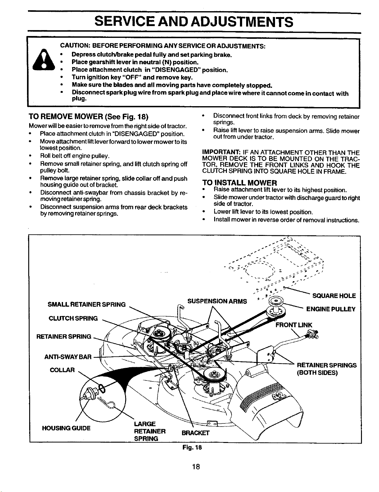
TO REMOVE MOWER (See Fig. 18)
Mower willbeeasier toremove from the rightside of tractor.
• Place attachment clutch in "DISENGAGED" position.
• Move attachment liftlever forward to lower mower toits
lowest position.
• Rollbelt off engine pulley.
• Remove small retainer spring, and liftclutch spring off
pulley bolt.
• Remove large retainer spring, slidecollar offand push
housingguide out ofbracket,
• Disconnect anti-swaybar from chassis bracket by re-
moving retainerspring.
• Disconnect suspension arms from rear deck brackets
byremoving retainer springs.
• Disconnect front linksfrom deck by removing retainer
spnngs.
• Raise lift lever to raise suspension arms. Slide mower
out from under tractor.
IMPORTANT: IF AN AI-rACHMENT OTHER THAN THE
MOWER DECK IS TO BE MOUNTED ON THE TRAC-
TOR, REMOVE THE FRONT LINKS AND HOOK THE
CLUTCH SPRING INTO SQUARE HOLE IN FRAME.
TO INSTALL MOWER
Raise attachment lift lever to itshighest position.
• Slide mower under tractor with discharge guard toright
side of tractor.
• Lower lift lever to its lowest position,
• Install mower in reverse order of removal instructions.
SMALL RETAINER SPRING
CLUTCH SPRING
RETAINER SPRING
"="_'_%"" _ SQUARE HOLE
SUSPENSION ARMS
ENGINE PULLEY
FRONT UNK
ANTI-SWAY BAR
COLLAR
RETAINER SPRINGS
(BOTH SIDES)
HOUSING GUIDE
LARGE
RETAINER BRACKET
SPRING
Fig. 18
18
SERVICE AND ADJUSTMENTS
TO LEVEL MOWER HOUSING
Adjust the mower while tractor isparked on level ground or
driveway. Make sure tires are propedy inflated (See "PROD-
UCT SPECIFICATIONS" section ofthismanual). Iftiresare
over or underinflated, you will not properly adjust your
mower.
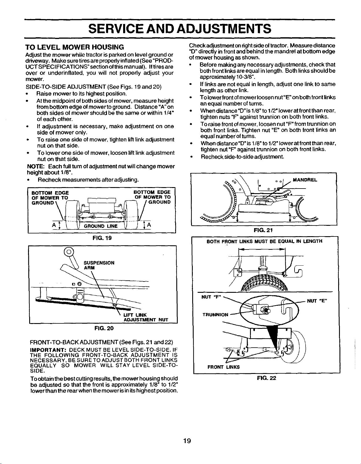
SIDE-TO-SIDE ADJUSTMENT (See Figs. 19 and 20)
• Raise mower to its highest position.
• At the midpoint of both sides of mower, measure height
from bottom edge of mower to ground. Distance"A" on
both sides of mower should be the same or within 1/4"
of each other.
• If adjustment is necessary, make adjustment on one
side of mower only.
• To raise one side of mower, tighten lift link adjustment
nut on that side.
• To lower one side of mower, loosen lift link adjustment
nut on that side.
NOTE: Each full turn of adjustment nut will change mower
height about 1/8".
• Recheck measurements after adjusUng.
BoTroM EDGE BOTTOM EDGE
OF MOWER TO OF MOWER TO
GROUND __ GROUND
FIG. 19
SUSPENSION
ARM
LIFT LINK
ADJUSTMENT NUT
FIG. 20
FRONT-TO-BACK ADJUSTMENT (See Figs. 21 and 22)
IMPORTANT: DECK MUST BE LEVEL SIDE-TO-SIDE. IF
THE FOLLOWING FRONT-TO-BACK ADJUSTMENT IS
NECESSARY, BE SURE TO ADJUST BOTH FRONT LINKS
EQUALLY SO MOWER WILL STAY LEVEL SIDE-TO-
SIDE.
To obtain the best cutting results, the mower housing should
be adjusted so that the front is approximately 1/8" to 1/2"
lower than the rear when the mower is inits highest position.
Check adjustmentonrightside oftractor. Measure distance
"D" directly in front and behind the mandrel at bottom edge
of mower housingas shown.
• Before makingany necessary adjustments, check that
bothfrontlinksareequal in length. Bothlinksshould be
approximately 10-3/8".
• If linksare not equal in length, adjust one linkto same
length as other link.
• Tolower front ofmewerloosen nut"E'on bothfront links
an equal number of turns.
• When distance"D" is 1/8" to 1/2" lower at front than rear,
tighten nuts "P'_against trunnion on both front links.
• To raise front of mower, loosen nut "F" from trunnion on
both front links. Tighten nut "E' on both front links an
equal numberof turns.
• When distance =D"is1/8" to 1/2" Iowerat front than rear,
tighten nut "F"against trunnion on both front links.
• Recheck side-to-side adjustment.
MANDREL
FIG. 21
BOTH FRONT LINKS MUST BE EQUAL IN LENGTH
NUT "F" -_
TRUNNIO_ NUT =E"
FRONT LINKS
FIG. 22
19
SERVICE AND ADJUSTMENTS
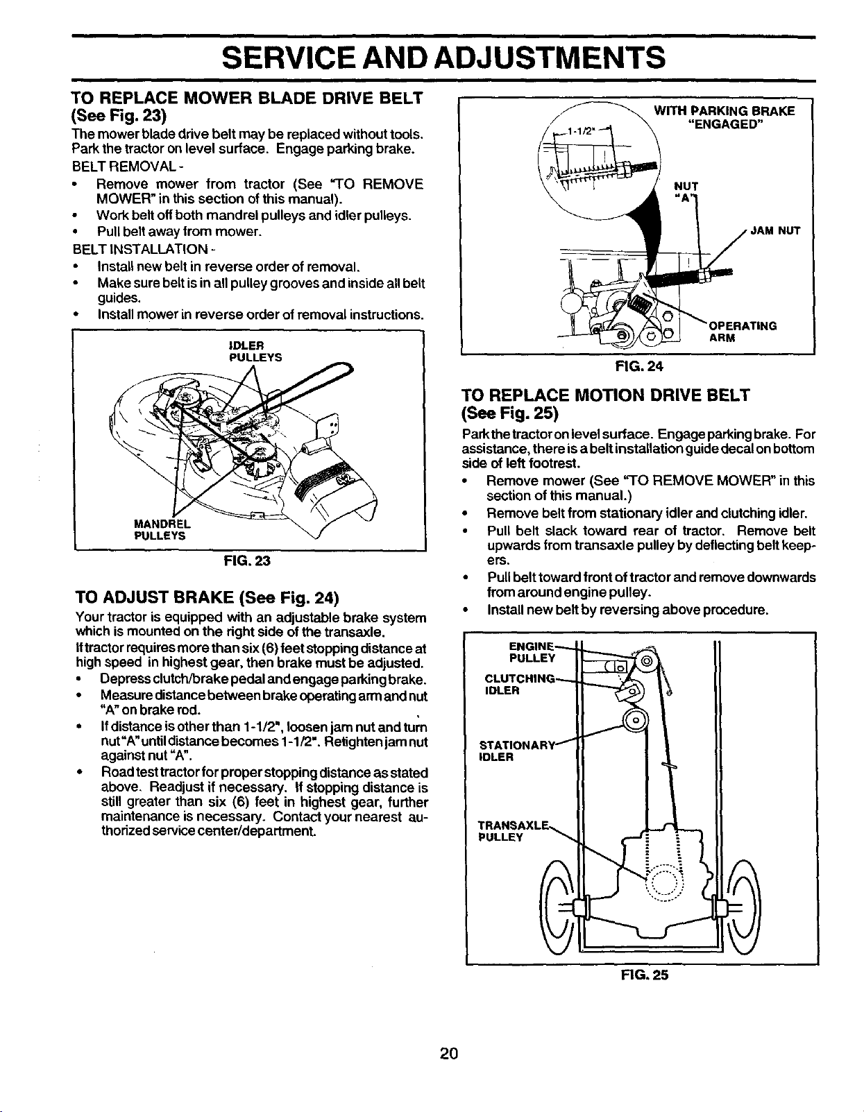
TO REPLACE MOWER BLADE DRIVE BELT
(See Fig. 23)
The mower blade drive belt may be replaced without tools.
Park the tractor on level surface. Engage parking brake.
BELT REMOVAL -
• Remove mower from tractor (See "TO REMOVE
MOWER" in this section of this manual).
Work belt offboth mandrel pulleys and idler pulleys.
• Pullbelt away from mower.
BELT INSTALLATION -
• Install new belt in reverse order of removal.
Make sure belt is in all pulley grooves and inside all belt
guides.
• Install mower in reverse order of removal instructions.
IDLER
PULLEYS
FIG. 23
TO ADJUST BRAKE (See Fig. 24)
Your tractor is equipped with an adjustable brake system
which ismounted on the right side of the transaxle.
Iftractor requiresmore than six (6) feet stoppingdistance at
high speed in highest gear, then brake mustbe adjusted.
• Depress clutch/brake pedal and engage parkingbrake.
• Measure distancebetween brake operating armand nut
"A"on brake rod.
• Ifdistance isother than 1-1/2", loosen jam nut and turn
nut"A"untildistance becomes 1-1/2". Retighten jam nut
against nut =A'.
• Roadtest tractorfor proper stopping distanceas stated
above. Readjust if necessary. If stopping distance is
still greater than six (6) feet in highest gear, further
maintenance isnecessary. Contact your nearest au-
thorizedservice center/department.
/
WITH PARKING BRAKE
"ENGAGED"
1 _ NUT
"_ JAM NUT
I1 _/_,_ I "OPERATING
ARM
FIG. 24
TO REPLACE MOTION DRIVE BELT
(See Fig. 25)
Parkthetractoron level surface. Engage parkingbrake. For
assistance, there isa belt installation guide decal onbottom
side of left footrest.
• Remove mower (See "1O REMOVE MOWER in this
section of this manual.)
• Remove belt from stationary idler and clutchingidler.
• Pull belt slack toward rear of tractor. Remove belt
upwards from transaxle pulley by deflecting belt keep-
ers.
• Pullbelt toward frontof tractor and remove downwards
from around engine pulley.
• Install new belt by reversing above procedure.
PULLEY
IDLER
iDLER
PULLEY
FIG, 25
2O
SERVICE AND ADJUSTMENTS
,1|
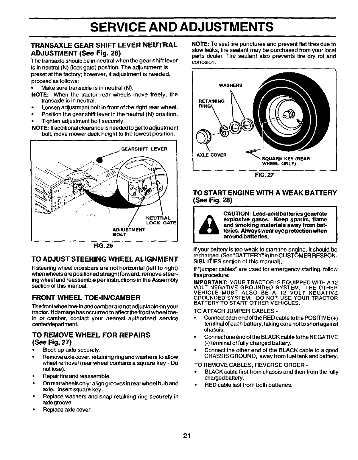
TRANSAXLE GEAR SHIFT LEVER NEUTRAL
ADJUSTMENT (See Fig. 26)
The transaxle shouldbe in neutral when the gear shift lever
isin neutral (N) (lock gate) position.The adjustment is
preset at the factory; however, ifadjustment is needed,
proceed as follows:
• Make sure transaxle isin neutral (N).
NOTE: When the tractor rear wheels move freely, the
transaxle is in neutral.
• Loosenadjustment bolt infront ofthe right rear wheel.
• Positionthe gear shift lever in the neutral (N) position.
• Tighten adjustment bolt securely.
NOTE: Ifadditionalclearance isneededtogettoadjustment
bolt,move mower deck height to the lowest position.
_..._GEARSHIFTLEVER
NEUTRAL
LOCK GATE
ADJUSTMENT
BOLT
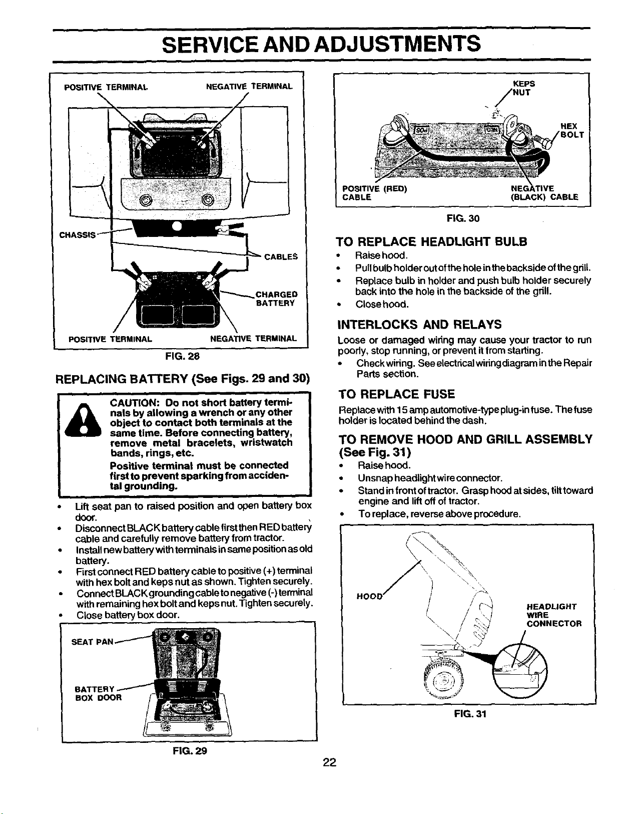
NOTE: To seal tire punctures and prevent flat tires due to
slow leaks, tire sealant may be purchased from your local
parts dealer. Tire sealant also prevents tire dry rot and
corrosion.
WASHERS
RETAINING
AXLE COVER
_SOUARE KEY (REAR
WHEEL ONLY)
FIG. 27
TO START ENGINE WITH A WEAK BAI-rERY
(See Fig. 28)
&
CAUTION: Lead-acid batteries generate
explosive gases. Keep sparks, flame
and smoking materials away from bat-
teries. Always wear eye protection when
around batteries.
FIG. 26
TO ADJUST STEERING WHEEL ALIGNMENT
If steering wheel crossbars are not horizontal (left to right)
when wheels are positioned straightforward, remove steer-
ingwheel and reassemble per instructions in the Assembly
section of this manual.
FRONT WHEEL TOE-IN/CAMBER
The front wheel toe-inand camber arenotadjustable on your
tractor. If damage has occurred to affect the front wheel toe-
in or camber, contact your nearest authodzed service
canter/department.
TO REMOVE WHEEL FOR REPAIRS
(See Fig. 27)
• Block up axle securely.
Remove axle cover,retaining ringand washers toallow
wheel removal (rear wheel contains a square key - Do
not lose).
Repair tire and reassemble.
• Onrearwheels only:align groovesinrear wheel hub and
axle. Insert square key.
• Replace washers and snap retaining ring securely in
axlegroove.
• Replace axle cover.
If your battery istoo weak to start the engine, it shouldbe
recharged.(See "BATTERY" inthe CUSTOMER RESPON-
SIBILITIES section of this manual).
If "jumper cables" are used for emergency starting, follow
thisprocedure:
IMPORTANT: YOUR TRACTOR IS EQUIPPED WITH A 12
VOLT NEGATIVE GROUNDED SYSTEM. THE OTHER
VEHICLE MUST ALSO BE A 12 VOLT NEGATIVE
GROUNDED SYSTEM. DO NOT USE YOUR TRACTOR
BATTERY TO START OTHER VEHICLES.
TO ATTACH JUMPER CABLES -
• Connecteachend ofthe RED cable tothePOSITIVE (+)
terminalofeach battery, takingcare nottoshortagainst
chassis.
• Connect oneend ofthe BLACK cabletothe NEGATIVE
(-) terminal offully charged battery.
• Connect the other end of the BLACK cable to a good
CHASSIS GROUND, away from fuel tankand battery.
TO REMOVE CABLES, REVERSE ORDER -
• BLACKcable first from chassis and then from the fully
charged battery.
RED cable lastfrom both batteries.
21
i
SERVICE AND ADJUSTMENTS
POSITIVE TERMINAL
NEGATIVE TERMINAL
CHARGED
BATTERY
POSITIVE TERMINAL NEGATIVE TERMINAL
FIG. 28
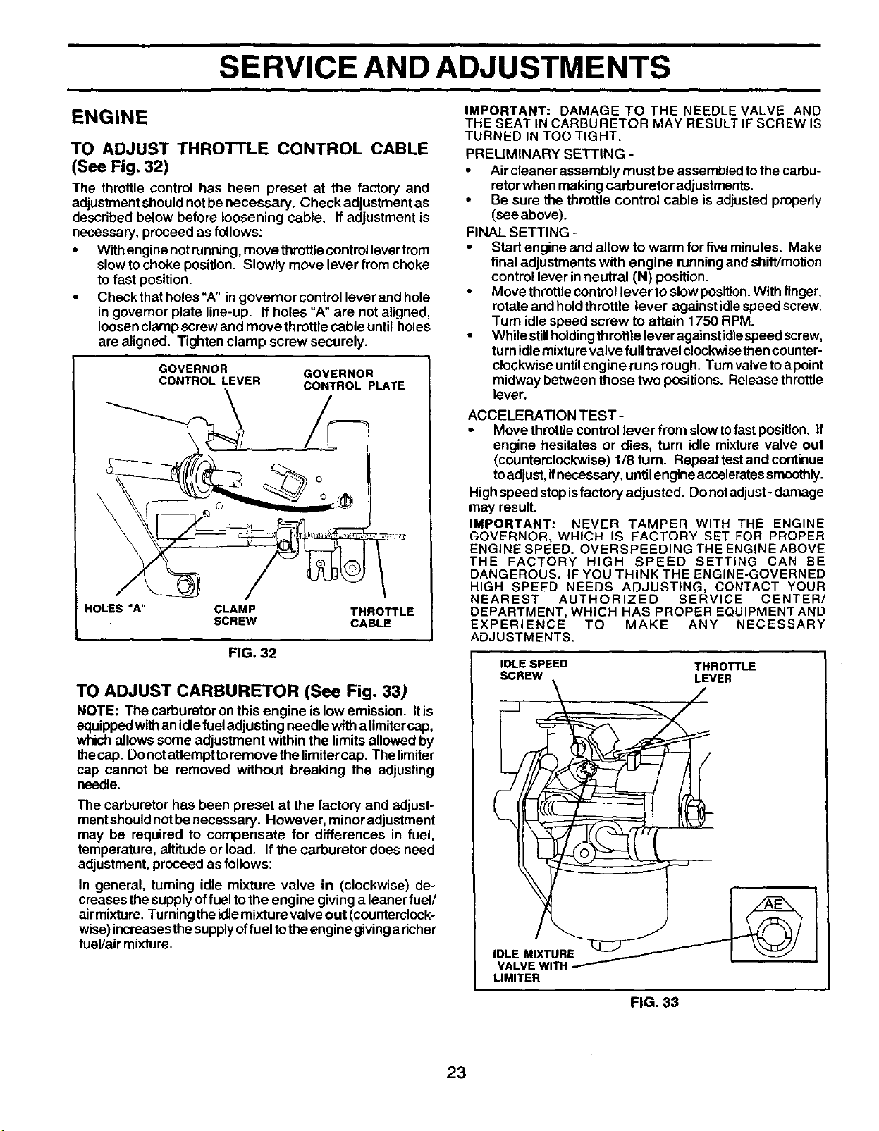
REPLACING BATI'ERY (See Figs. 29 and 30)
CAUTION: Do not short battery termi-
nals by allowing a wrench or any other
object to contact both terminals at the
same time. Before connecting battery,
remove metal bracelets, wristwatch
bands, rings, etc.
Positive terminal must be connected
first to prevent sparking from acciden-
tal grounding.
i
Lift seat pan to raised position and open battery box
door.
Disconnect BLACK battery cable first then RED batte_
cable and carefully remove battery from tractor.
Install new battery with terminals in same position as old
battery.
Firstconnect RED battery cable topositive (+) terminal
with hex boltand keps nut as shown. Tighten securely.
Connect BLACKgrounding cable tonegative(-)terminal
with remaining hex boltand keps nut.Tighten securely.
Close battery box door.
SEATI
BATTER_
BOX DOOR
KEPS
!NUT
HEX
POSITIVE (RED) NEGATIVE
CABLE (BLACK) CABLE
FIG. 30
TO REPLACE HEADLIGHT BULB
• Raise hood.
• Pullbulb holder outofthe holeinthebackside ofthe grill.
• Replace bulb in holderand push bulb holder securely
back into the hole in the backside ofthe gdll.
• Close hood.
INTERLOCKS AND RELAYS
Loose or damaged wiring may cause your tractor to run
poody, stop running, orprevent itfrom starting.
• Checkwiring. See electrical widng diagram inthe Repair
Parts section.
TO REPLACE FUSE
Replace with 15 amp automotive-typeplug-infuse. The fuse
holder islocated behind the dash.
TO REMOVE HOOD AND GRILL ASSEMBLY
(See Fig. 31)
• Raise hoed.
• Unsnap headlight wire connector.
• Stand in frontoftractor. Grasp hoodat sides,tilttoward
engine and lift off oftractor.
• To replace, reverse above procedure.
/ HEADLIGHT
WIRE
\
-. CONNECTOR
FIG. 31
FIG. 29
22
SERVICE AND ADJUSTMENTS
ENGINE
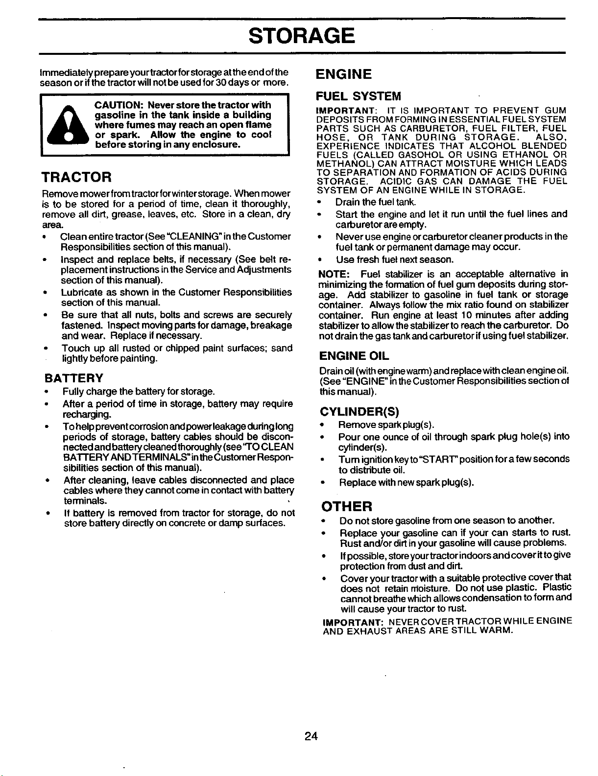
TO ADJUST THROTTLE CONTROL CABLE
(See Fig. 32)
The throttle control has been preset at the factory and
adjustmentshould notbe necessary. Check adjustment as
described below before loosening cable. If adjustment is
necessary, proceed as follows:
• Withenginenot running,move throttlecontrolleverfrom
slowto choke position. Slowly move lever from choke
to fast position.
• Check thatholes "A" in governor control lever and hole
in governor plate line-up. If holes "A"are not aligned,
loosen clamp screw and move throttle cable until holes
are aligned. Tighten clamp screw securely.
GOVERNOR
CONTROL LEVER
GOVERNOR
CONTROL PLATE
\
HOLES"A" CLAMP THROTTLE
SCREW CABLE
FIG. 32
TO ADJUST CARBURETOR (See Fig. 33)
NOTE: The carburetor on this engine is low emission. Itis
equippedwithan idlefueladjusting needle witha limitercap,
whichallows some adjustment within the limitsallowed by
thecap. Do notattempttoremove the limitercap. The limiter
cap cannot be removed without breaking the adjusting
needle.
The carburetor has been preset at the factory and adjust-
mentshouldnotbe necessary. However, minor adjustment
may be required to compensate for differences in fuel,
temperature, altitude or load. If the carburetor does need
adjustment, proceed as follows:
In general, turning idle mixture valve in (clockwise) de-
creases the supply offuel to the engine givinga leaner fuel/
airmixture. Turningtheidlemixturevalve out (counterclock-
wise)increasesthesupplyoffuel totheengine givinga richer
fuel/air mixture.
IMPORTANT: DAMAGE TO THE NEEDLE VALVE AND
THE SEAT IN CARBURETOR MAY RESULT IF SCREW IS
TURNED IN TOO TIGHT.
PRELIMINARY SETTING -
• Aircleaner assembly must be assembled tothe carbu-
retorwhen making carburetor adjustments.
• Be sure the throttle control cable is adjusted properly
(see above).
FINAL SETTING -
• Start engine and allow to warm for five minutes. Make
final adjustments with engine runningand shift/motion
control lever inneutral (N) position.
Move throttlecontrollever to slow position.With finger,
rotate and hold throttle lever againstidlespeed screw.
Turn idle speed screw to attain 1750 RPM.
• While stillholdingthrottle lever againstidlespeed screw,
turnidlemixtu revalve full travel clockwisethencounter-
clockwise untilengine runs rough. Turn valvetoa point
midway between those two positions. Release throttle
lever.
ACCELERATION TEST-
• Move throttle control lever from slow to fast position. If
engine hesitates or dies, turn idle mixture valve out
(counterclockwise) 1/8turn. Repeattest and continue
toadjust, ifnecessary, until engine accelerates smoothly.
High speed stop isfactory adjusted. Do not adjust- damage
may result.
IMPORTANT: NEVER TAMPER WITH THE ENGINE
GOVERNOR, WHICH IS FACTORY SET FOR PROPER
ENGINE SPEED. OVERSPEEDING THE ENGINE ABOVE
THE FACTORY HIGH SPEED SETTING CAN BE
DANGEROUS. IF YOU THINK THE ENGINE-GOVERNED
HIGH SPEED NEEDS ADJUSTING, CONTACT YOUR
NEAREST AUTHORIZED SERVICE CENTER/
DEPARTMENT, WHICH HAS PROPER EQUIPMENT AND
EXPERIENCE TO MAKE ANY NECESSARY
ADJUSTMENTS.
IDLE SPEED THROTTLE
SCREW \ LEVER
LIMITER
FIG. 33
23
STORAGE
ENGINE
immediately prepare yourtractorforstorageatthe end ofthe
season or ifthe tractor willnot be used for 30 days or more.
CAUTION: Never store the tractor with
gasoline in the tank inside a building
where fumes may reach an open flame
or spark. Allow the engine to cool
before storing in any enclosure.
TRACTOR
Remove mower fromtractorforwinterstorage. When mower
is to be stored for a period of time, clean it thoroughly,
remove all dirt, grease, leaves, etc. Store in a clean, dry
area.
• Cleanentiretrector(See"CLEANING"intheCustomer
Responsibilities section of this manual).
inspect and replace belts, if necessary (See belt re-
placement instructionsinthe Service and Adjustments
section of this manual).
• Lubricate as shown in the Customer Responsibilities
section of this manual.
• Be sure that all nuts, bolts and screws are securely
fastened. Inspect moving partsfor damage, breakage
and wear. Replace ifnecessary.
• Touch up all rusted or chipped paint surfaces; sand
lightlybefore painting.
BATTERY
• Fully charge the battery for storage.
• After a period of time in storage, battery may require
recharging.
• To helpprevant corrosionandpowerleakage dudnglong
periods of storage, battery cables should be discon-
nected and battery cleanedthoroughly (see "TO CLEAN
BAT"FERYAND TERMINALS" intheCustomer Respon-
sibilities section of this manual).
• After cleaning, leave cables disconnected and place
cables where they cannot comein contact with battery
terminals.
• If battery is removed from tractor for storage, do not
store battery directly on concrete or damp surfaces.
FUEL SYSTEM
IMPORTANT: IT IS IMPORTANT TO PREVENT GUM
DEPOSITS FROM FORMING IN ESSENTIAL FUEL SYSTEM
PARTS SUCH AS CARBURETOR, FUEL FILTER, FUEL
HOSE, OR TANK DURING STORAGE. ALSO,
EXPERIENCE INDICATES THAT ALCOHOL BLENDED
FUELS (CALLED GASOHOL OR USING ETHANOL OR
METHANOL) CAN ATTRACT MOISTURE WHICH LEADS
TO SEPARATION AND FORMATION OF ACIDS DURING
STORAGE. ACIDIC GAS CAN DAMAGE THE FUEL
SYSTEM OF AN ENGINE WHILE IN STORAGE.
• Drain the fuel tank.
• Start the engine and let it run until the fuel lines and
carburetor are empty.
• Never use engine or carburetor cleaner products in the
fuel tank or permanent damage may occur.
• Use fresh fuel next season.
NOTE: Fuel stabilizer is an acceptable alternative in
minimizing the formation of fuel gum deposits dudng stor-
age. Add stabilizer to gasoline in fuel tank or storage
container. Always follow the mix ratio found on stabilizer
container. Run engine at least 10 minutes after adding
stabilizer to allowthe stabilizerto reach the carburetor. Do
not drain the gastankand carburetor ifusing fuel stabilizer.
ENGINE OIL
Drain oil(withenginewarm)and replace withclean engine oil.
(See "ENGINE" inthe Customer Responsibilities section of
this manual).
CYLINDER(S)
• Remove spark plug(s).
• Pour one ounce ofoil through spark plug hole(s) into
cylinder(s).
• Tum ignitionkeyto"START" positionfor a few seconds
to distdbute oil.
• Replace with newspark plug(s).
OTHER
• Do not store gasolinefrom one season to another.
• Replace your gasoline can if your can starts to rust.
Rust and/or dirtinyour gasoline will cause problems.
• Ifpossible, storeyourtractor indoorsand cover ittogive
protection fromdust and dirt.
• Cover your tractorwith a suitable protective cover that
does not retainnloisture. Do not use plastic. Plastic
cannot breathe whichallowscondensation to form and
will cause yourtractorto rust.
IMPORTANT: NEVERCOVER TRACTOR WHILE ENGINE
AND EXHAUST AREAS ARE STILL WARM.
24
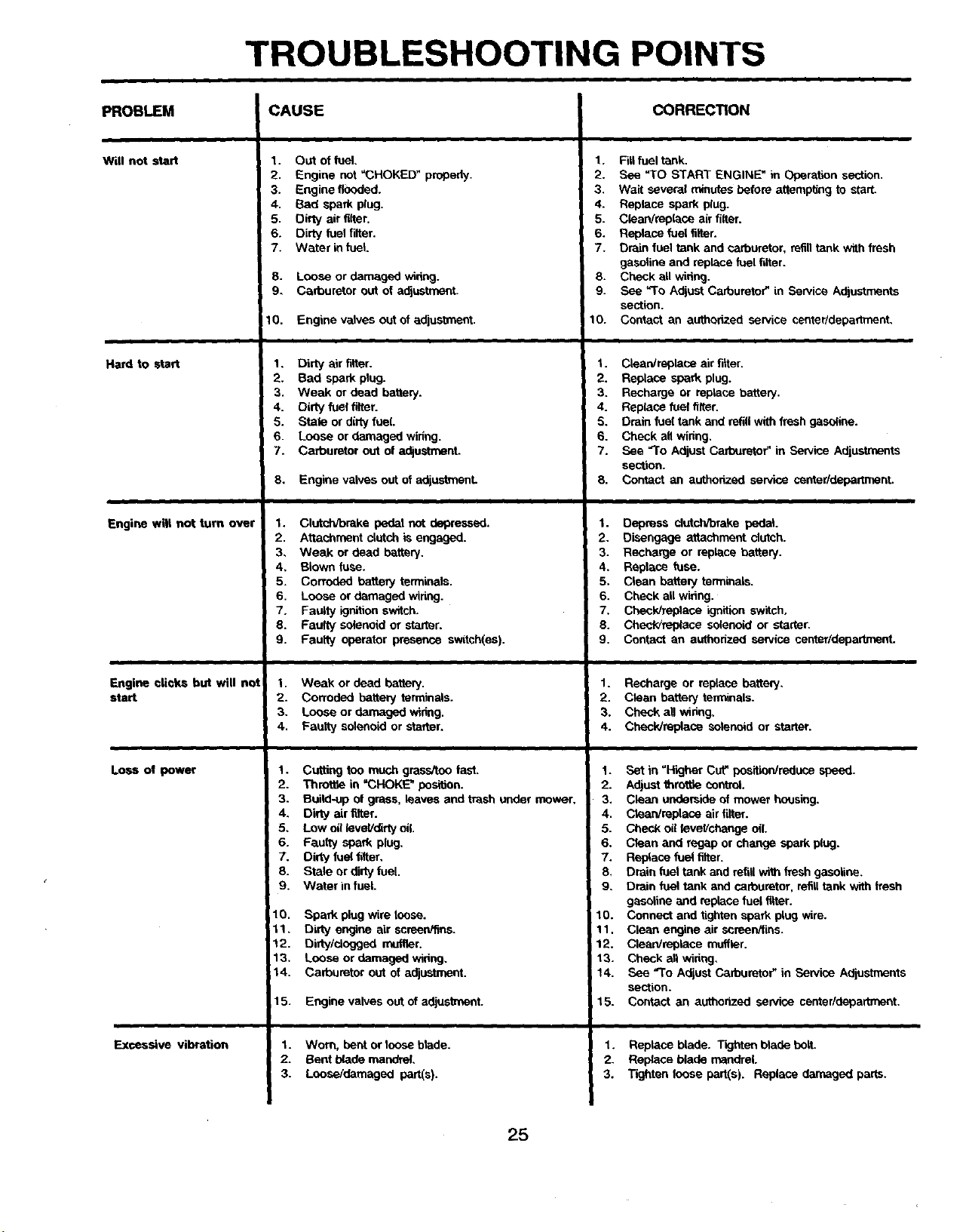
TROUBLESHOOTING POINTS
PROBLEM
Will not start
Hard to start
Engine wilt not turn over
Engine clicks but will not
start
Loss of power
Exsessive vibration
CAUSE
1. Out of fuel,
2. Engine not =CHOKED" properly.
3. Engine flooded.
4, Sad spark plug,
5, Dirty air filter,
6. Dirty fuel f'dler.
7. Water infuel.
8. Loose or darnagad widng.
9, Carburetor out of adjustment.
10. Engine valves out of adjustment.
1. Dirty air filler.
2. Bad spark plug.
3. Weak or dead battery.
4. Dirty fuel filter.
5. Stale or dirty fuel
6. Loose or damaged wiring.
7. Carburetor out of adjustment.
8, Engine valves out of adjustment
1. Clutchibrake pedal not depressed.
2. Attachment clutch is e_jaged.
3, Weak or dead battery.
4, Blown fuse.
5, Corroded battery terminals.
6. Loose or damaged wiring.
7, Faulty ignition switch.
8. Faulty solenoid or starer.
9. Faulty operator presence switch(es).
1. Weak or dead bakery.
2. Corroded battery terminals.
3. Lease or damaged wiring.
4. Faulty solenoid or starter.
1.
2.
3.
4,
5,
6.
7.
8.
9.
10.
11.
12.
13.
14.
Cutting too much grass/too last.
Throt_e in =CHOKE" position.
Build-up of grass, leaves and trash under mower.
Dirty air filter.
Low oil leveVdirty oil.
Faulty spark plug.
Dirty fuel filter,
Stale or dirty fuel.
Water in fuel.
Spark plug wire loose.
Dirty engine air screen/fins.
Dirty/dogged muffler.
Loose or damaged widng,
Carburetor out of adjustment,
15. Engine valves out of adjus_nent.
1. Worn, bent or loose blade.
2. Sent blade mandrel,
3. Loose/damuged part(s).
CORRECTION
1. Fill fuel tank.
2. See "TO START ENGINE _ in Operation section.
3. Wait several minutes before attempting to start.
4. Replace spark plug.
5. ClearVreplace air filler.
6. Replace fuelfilter.
7. Drain fuel tank and ¢arburetor, refill tank with fresh
gasoline and replace fuel tiller.
8. Check all wiring.
9. See =1-o Adjust Carburetor" in Service Adjustments
section.
10. Contact an authorized service center/department,
1. Clean'replace air filter.
2. Replace spark plug.
3. Recharge or replace battery.
4. Replace fuel filter.
5. Drain fuel tank and refill with fresh gasoline.
6. Check all wiring,
7. See =To Adjust Carburetor" in Service Adjustments
section.
8. Contact an authonzed service center/departrnent.
1. Depress clutch_rake pedal.
2. Disengage attachment clutch.
3. Recharge or replace battery.
4. Replace fuse.
5. Clean batteryterminals.
6. Check all wiring.
7. Check/replace ignition switch.
8. Check/replece solenoid or starter.
9. Contact an authorized service center/department,
1. Recharge or replace battery,
2. Cleen battery terminals.
3. Check all wiring,
4. Check/replase solenoid or starter.
1. Set in "Higher Cut" pos_reduce speed.
2. Adjust throttle central
3. Clean underside of mower housing,
4. Clean/replace air filter.
5. Check oil leveVehsege oil.
6. Clean and regep or change spark plug.
7. Replace fuel filter.
8, Drain fuel tank and refill with fresh gasoline.
9. Drain fuel tank and carburetor, refilllank vidh flesh
gasoline and replace fuel filter.
10. Connect and tighten spark plug wire.
11. Clean engine air screen/fins.
12. Clean/replace muffler,
13. Check all wiring,
14. See =To Adjust Carburetor" in Service Adjustments
section.
15. Contact an authorized service centerldepadment.
1. Replace blade. T'_jhten blade bolt.
2. Replace blade mandrel.
3. Tighten loose part(s). Replace damaged parts.
25
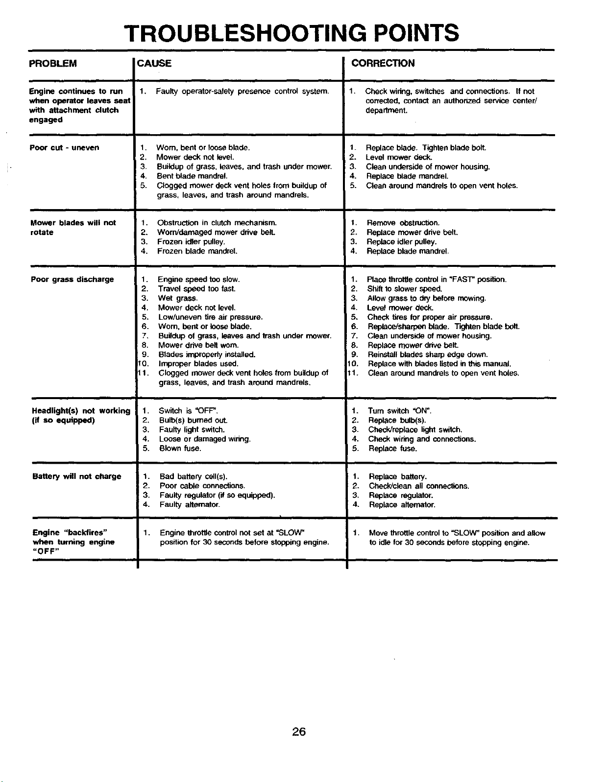
TROUBLESHOOTING POINTS
PROBLEM
Engine continues to run
when operator leaves seat
with attachment clutch
engaged
Poor cut - uneven
Mower blades will not
rotate
poor grass discharge
Headlight(s) not working
(if so equipped)
Battery will not charge
Engine "backfires"
when turning engine
=OFF"
CAUSE
1. Faulty operator-safety presence control system.
1. Wom, bent or loose blade.
2. Mower deck not level.
3. Buildup of grass, leaves, and trash under mowen
4. Bent blade mandrel.
5. Clogged mower deck vent holes from buildup of
grass, leaves, and trash around mandrels.
t. Obstruction in clutch mechanism.
2. Worn/damaged mower drive belt.
3. Frozen idler pulley.
4. Frozen blade mandrel.
1. Engine speed too slow.
2. Travel speed too fast.
3. Wet grass.
4. Mower deck not level.
5. Low/uneven tire air pressure.
6. Wom, bent or loose blade.
7. Buildup ol grass, leaves and trash under mower.
8. Mower drive belt worn.
9. Blades improperly installed.
10. Improper blades used.
11. Clogged mower deck vent holes from buildup of
grass, leaves, and trash around mandrels.
1. Switch is "OFF".
2. Bulb(s) bumed out.
3. Faulty light switch.
4. Loose or damaged wiring.
5. Blown fuse.
1. Bad battery cell(s).
2. Poor cable connections.
3. Faulty regulator (if so equipped).
4. Faulty alternator.
1.
Engine throttle control not set at "SLOW"
position for 30 seconds before stopping engine.
CORRECTION
1. Check winng, switches and connections. If not
corrected, contact an authorized service center/
department.
1. Replace blade. Tighten blade bolt.
2. Level mower deck.
3. Clean underside of mower housing.
4. Replace blade mandrel.
5. Clean around mandrels to open vent holes.
1. Remove obstruction.
2. Replace mower drive belt.
3. Replace idler pulley.
4. Replace blade mandrel.
1. Place throttle control in "FAST" position.
2. Shift to slower speed.
3. Allow grass to dry before mowing.
4. Level mower deck.
5. Check tires for proper air pressure.
6. Replace/sberpen blade, Tighten blade bolt.
7. Clean underside of mower housing.
8. Replace mower drive bell
9. Reinstal! blades sharp edge down.
10. Replace with blades listed in this manual.
11. Clean around mandrels to open vent holes.
1. Tum switch "ON_.
2. Replace bulb(s).
3. Check/replace light switch.
4. Check wiring and connections.
5. Replace fuse.
1. Replace battery.
2. Check/clean all connections.
3. Replace regulator.
4. Replace aitemator.
1. Move throttle controlto "SLOW" position and allow
to idle for 30 seconds before stopping engine.
26
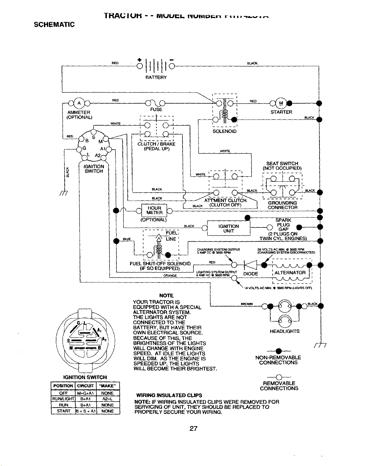
SCHEMATIC
THAL; I UH - - IVIUUI¢l. IIUIVil_r.n r i a,, -_.v, ._
BATrERY
F-, _ G A1
_ SWITCH
IGNITION SWITCH
FUSE
i I i
L J
CLUTCH/ BRAKE
(PEDALUP)
POSITION CIRCUIT "MAKE"
OFF M+G+A1 NONE
RUN/LIGHT B+At A2+L
RUN B+A1 NONE
START IB + S + A1 NONE
BLACK
_LACK
METER
(OPTIONAL)
SOLENOID
STARTER
BLACK
', FUE_
BLACK
_FnE
SEAT SWITCH
......... , (NOT OCCUPIED)
"@
I I t I I
e_c_ (CLUTCH OFF) I
CONNECTOR
,GNTON ,---
UNIT] (2 PLUGS,ON
TWIN CYL ENGINES)
CHARGING SYSTEM OUTPUT
3 AMP DC @ _=00 RPM
28 VOLTS AC M_I @ 3600 RPM
(CHARGING SYS3_M DISCONNECrlE_
RED
FUEL SHUT-OFF SOLENOID
(IF SO EQUIPPED) I
DIODE LLALTERNATOR
LIGHTLNG SY_TIEM OUTPUT
O_ANGE 5 AMP AC O 3600 RP_ (_
i'
NOTE |
YOUR TRACTOR IS | SROWN _ _ _=F_SLAC_,
EQUIPPED WITH A SPECIAL " _
ALTERNATOR SYSTEM. I _ I
THE LIGHTS ARE NOT I If-% I )
CONNECTED TO THE '_ _'_ I
BA'i-I'ERY, BUT HAVE THEIR _1
OWN ELECTRICAL SOURCE. HEADLIGHTS {
BECAUSE OF THIS. THE |
BRIGHTNESS OF THE LIGHTS
WILL CHANGE WITH ENGINE ''"
SPEED. AT IDLE THE LIGHTS _"
WILL DIM. ASTHE ENGINE IS NON-REMOVABLE
SPEEDED UP, THE LIGHTS CONNECTIONS
WILL BECOME THEIR BRIGHTEST.
©
REMOVABLE
CONNECTIONS
WIRING INSULATED CLIPS
NOTE: IF WIRING INSULATED CLIPS WERE REMOVED FOR
SERVICING OF UNIT. THEY SHOULD BE REPLACED TO
PROPERLY SECURE YOUR WIRING.
27
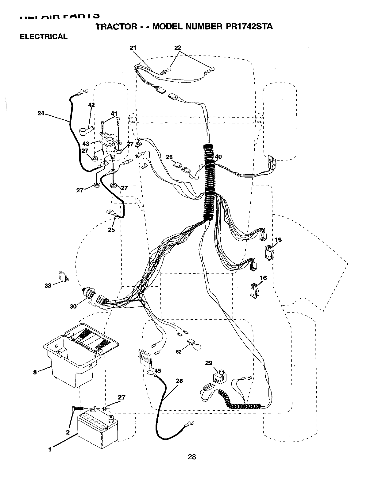
• ig--z /'_In iF/-in ii ,_)
TRACTOR - - MODEL NUMBER PR1742STA
ELECTRICAL
27
/
/
/
/
I
I
L
\
41
i I
\ I
26
/
I
I
i
i
I 1 t
i I t
I I I
t
I
I
\
I
I
I
i I
!
\
- j
I
I
I
I
/

REPAIR PARTS
TRACTOR - - MODEL NUMBER PR1742STA
ELECTRICAL
KEY PART
NO. NO. DESCRIPTION
1 144925
2 74760412
8 156417
16 15,3664
21 166181
22 4152J
24 4799,,I
25 146147
26 166180
27 73510400
28 4207J
29 121305X
30 163968
33 140401
40 170217
41 71110408
42 131563
43 145673
45 121433X
52 141940
Battery 12 Volt 25 Amp
Bolt Hex Hd 1/4-20unc X 3/4
Case Battery Mech Hinge
Switch Intedeck Push-in
Harness Socket Light
Bulb, Light # 1156
Cable Battery
Cable Battery 6 Ga Red w/16 wire
Fuse 15 Amp
Nut Keps Hex 1/4-20 Unc
Cable Ground 6ga t2 black
Switch Plunger Nc Gray
Switch Ign
Key Ign Molded Generic
Harness Ign
Bolt Fin Hex l/4-20uncx 1/2
Cover Terminal Red
Solenoid
Ammeter Rectangular
Protection Loop
NOTE: Allcomponent dimensions given in U.S. inches
1 inch = 25.4 mm
29
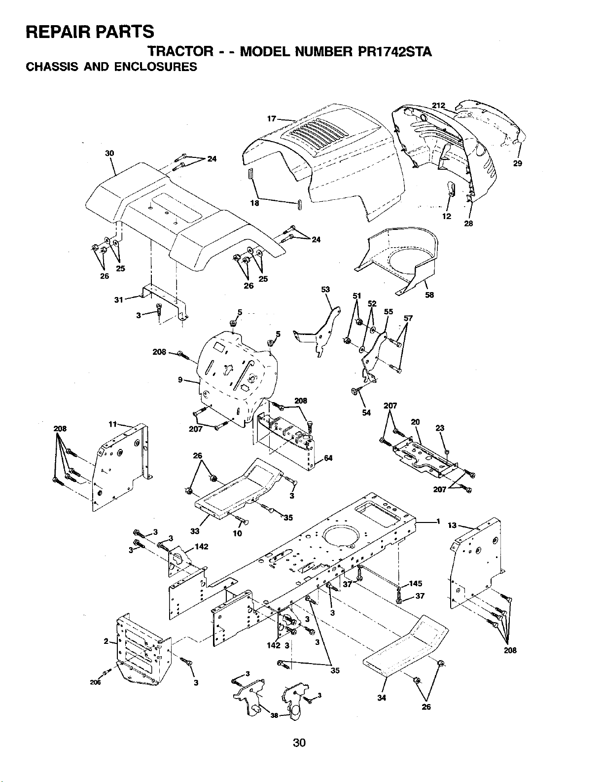
REPAIR PARTS
TRACTOR -- MODEL NUMBER PR1742STA
CHASSIS AND ENCLOSURES
3O
26
33
.142
25
26
5
53
54
I0
3
38
58
55
12
34
207
2O
23
26
28
29
2O8
30
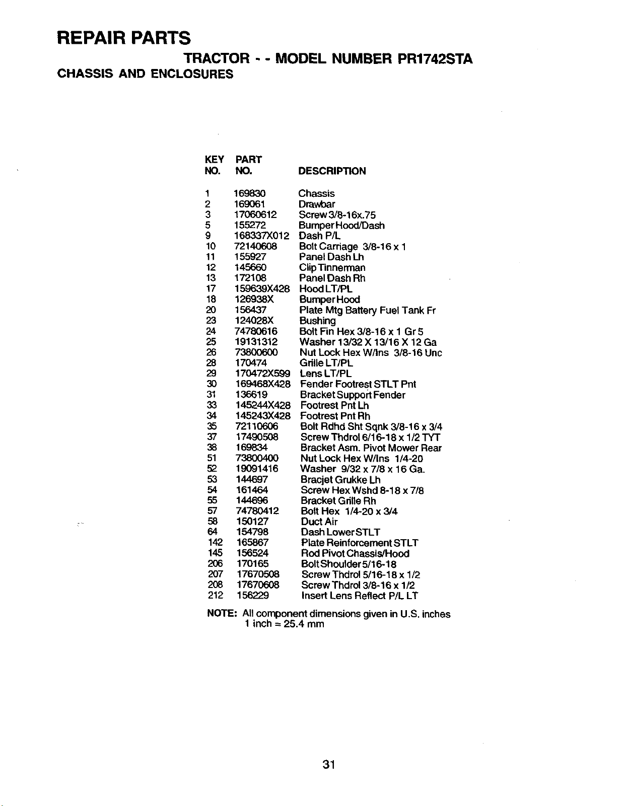
REPAIR PARTS
TRACTOR - - MODEL NUMBER PR1742STA
CHASSIS AND ENCLOSURES
KEY PART
NO. NO. DESCRIPTION
1 169830
2 169061
3 17060612
5 155272
9 168337X012
10 72140608
11 155927
12 145660
13 172108
17 159639X428
18 126938X
20 156437
23 124028X
24 74780616
25 19131312
26 738OO6OO
28 170474
29 170472X599
30 169468X428
31 136619
33 145244X428
34 145243X428
35 72110606
37 17490508
38 169834
51 73800400
52 19091416
53 144697
54 161464
55 144696
57 74780412
58 150127
64 154798
142 165867
145 156524
206 170165
207 17670508
208 17670608
212 156229
Chassis
Drawbar
Screw 3/8-16x.75
Bumper Hood/Dash
Dash P/L
BoltCarriage 3/8-16 x 1
Panel Dash Lh
Clip Tinnerman
Panel Dash Rh
Hood LT/PL
BumperHood
Plate Mtg Battery Fuel Tank Fr
Bushing
Bolt Fin Hex 3/8-16 x 1 Gr 5
Washer 13/32 X 13/16 X 12 Ga
Nut Lock Hex W/Ins 3/8-16 Unc
Gdlle LT/PL
Lens LT/PL
Fender Footrest STLT Pnt
Bracket SupportFender
Footrest Pnt Lh
Footrest PntRh
Bolt Rdhd Sht Sqnk 3/8-16 x 3/4
Screw Thdrol 6/16-18 x 1/2 TYT
Bracket Asm. Pivot Mower Rear
Nut Lock Hex W/Ins 1/4-20
Washer 9/32 x 7/8 x 16 Ga.
Bracjet Grukke Lh
Screw Hex Wshd 8-18 x 7/8
Bracket GdUeRh
Bolt Hex 1/4-20 x 3/4
Duct Air
Dash LowerSTLT
Plate Reinforcement STLT
Rod Pivot Chassis/Hood
BoltShoulder 5/16-18
Screw Thdrol 5/16-18 x 1/2
Screw Thdrol 3/8-16 x 1/2
Insert Lens Reflect P/L LT
NOTE: All component dimensions given in U.S. inches
1 inch = 25.4 mm
31
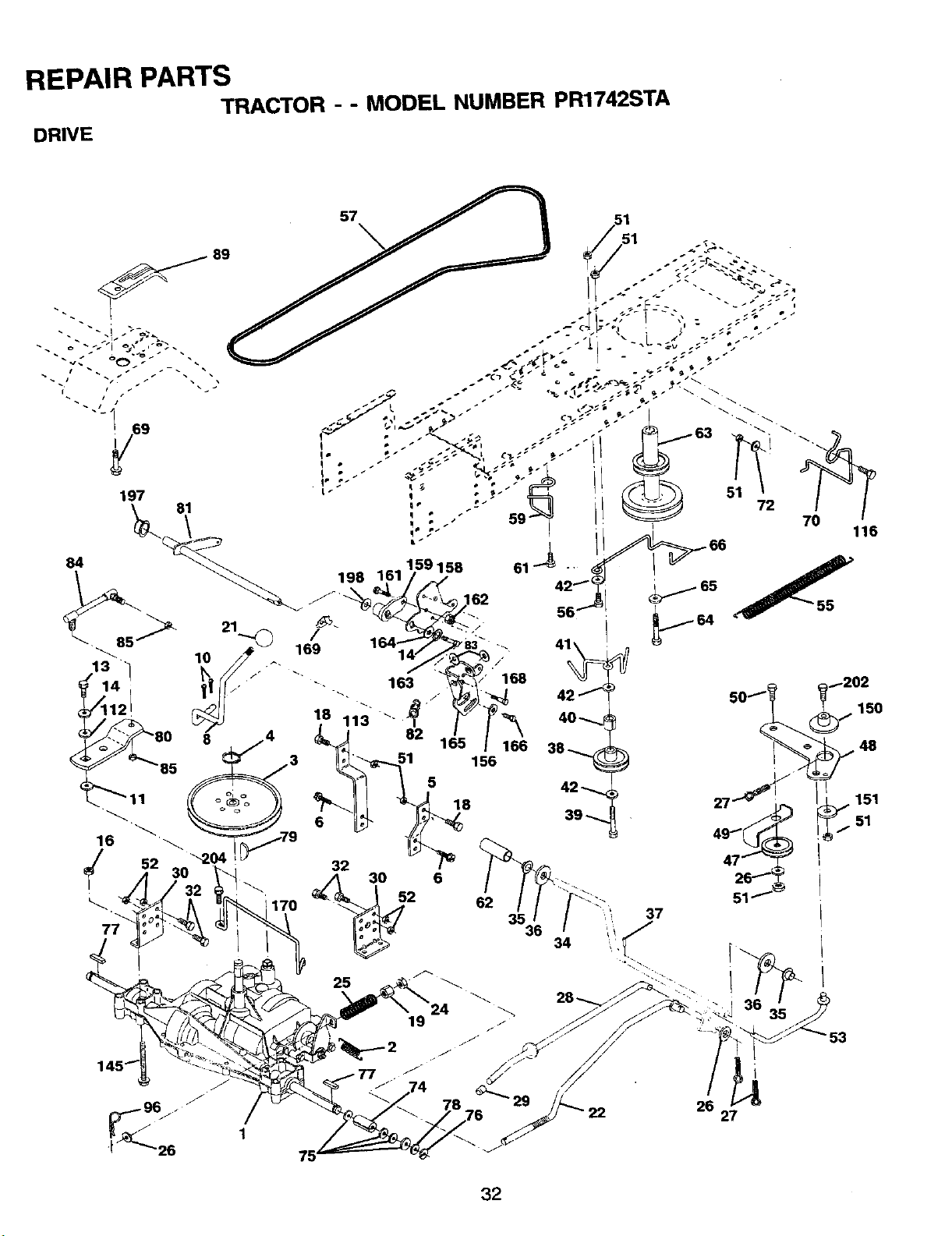
REPAIR PARTS
TRACTOR - - MODEL NUMBER PR1742STA
DRIVE
197
81
57
32
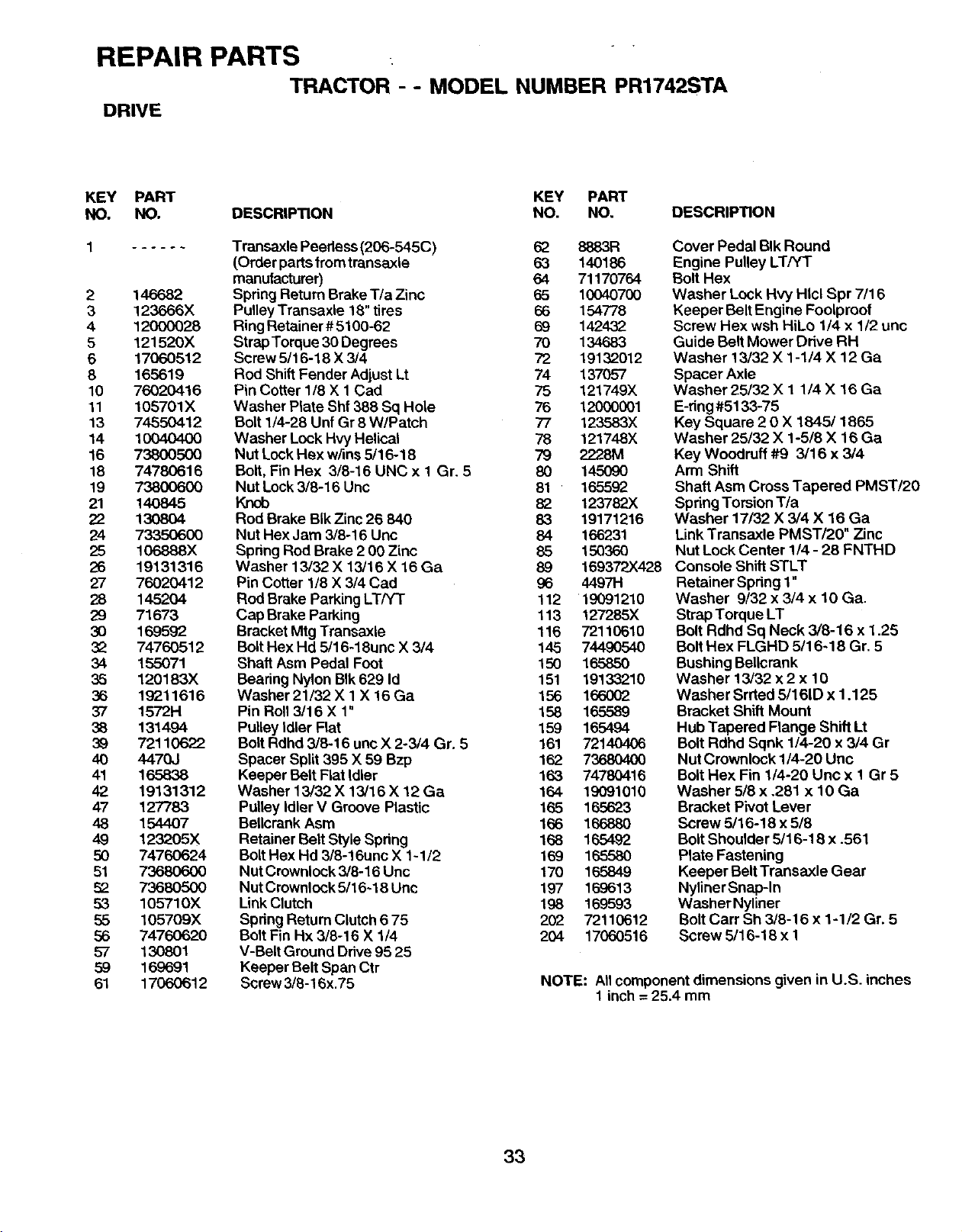
REPAIR PARTS ,
TRACTOR - - MODEL NUMBER PR1742STA
DRIVE
KEY PART KEY PART
NO. NO. DESCRIPTION NO. NO. DESCRIPTION
2 146682
3 123666X
4 12000028
5 121520X
6 17060512
8 165619
10 76020416
11 105701X
13 74550412
14 10040400
16 73800500
18 74780616
19 738(X)600
21 140845
22 130804
24 7335O6O0
25 106888X
26 19131316
27 76020412
28 145204
29 71673
30 169592
32 74760512
34 155071
35 120183)(
36 19211616
37 1572H
38 131494
39 72110622
4O 447O3
41 165838
42 19131312
47 127783
48 154407
49 123205X
50 74760624
51 73680600
52 73680500
53 105710X
55 105709)(
56 7476O620
57 130801
59 169691
61 17060612
Transaxle Peedess (206-545C) 62 8883R
(Order parts from transaxle 63 140186
manufacturer) 64 71170764
Spring Return Brake T/a Zinc 65 10040700
Pulley Transaxle 18" tires 66 154778
Ring Retainer # 5100-62 69 142432
Strap Torque 30 Degrees 70 134683
Screw 5/16-18 X 3/4 72 19132012
Rod ShiftFender Adjust Lt 74 137057
Pin Cotter 1/8 X 1 Cad 75 121749X
Washer Plate Shf 388 Sq Hole 76 12000001
Bolt 1/4-28 Unf Gr 8 W/Patch 77 123583X
Washer Lock Hvy Helical 78 121748X
Nut Lock Rex w/ms 5/16-18 79 2228M
Belt, Fin Hex 3/8-16 UNC x I Gr. 5 80 145090
Nut Lock 3/8-16 Unc 81 165592
Knob 82 123782X
Rod Brake BIkZinc 26 840 83 19171216
Nut Hex Jam 3/8-16 Uric 84 166231
Spring Rod Brake 2 00 Zinc 85 150360
Washer 13/32 X 13/16 X 16 Ga 89
Pin Cotter 1/8 X 3/4 Cad 96 44971-1
Rod Brake Parking LT/Yr 112 19091210
Cap Brake Parking 113 127285X
Bracket Mtg Transaxle 116 72110610
Bolt Hex Hd 5116-18unc X 3/4 145 74490540
Shaft Asm Pedal Foot 150 165850
Bearing Nylon BIk 629 Id 151 19133210
Washer 21/32 X 1 X 16 Ga 156 166002
Pin Roll 3/16 X 1" 158 165589
Pulley Idler Flat 159 165494
Bolt Rdhd 3/8-16 unc X 2-3/4 Gr. 5 161 72140406
Spacer Split 395 X 59 Bzp 162 73680400
Keeper Belt Flat Idler 163 74780416
Washer 13/32 X 13/16 X 12 Ga 164 19091010
Pulley Idler V Groove Plastic 165 165623
Bellcrank Asm 166 166880
Retainer Belt Style Spring 168 165492
Bolt Hex Hd 3/8-16unc X 1-1/2 169 165580
Nut Crownlock 3/8-16 Unc 170 165849
Nut Crownlock 5/16-18 Unc 197 169613
Link Clutch 198 169593
Spdng Return Clutch6 75 202 72110612
Bolt Fin Hx 3/8-16 X 1/4 204 17060516
V-Belt Ground Drive95 25
Keeper Belt Span Ctr
Screw 3/8-16x.75
Cover Pedal BIk Round
Engine Pulley LT/YT
Bolt Hex
Washer Lock Hvy HIcl Spr 7/16
Keeper Belt Engine Foolproof
Screw Hex wsh HiLo 1/4 x 1/2 unc
Guide Belt Mower Drive RH
Washer 13/32 X 1-1/4 X 12 Ga
Spacer Axle
Washer 25/32 X 1 1/4 X 16 Ga
E-dng#5133-75
Key Square 2 0 X 1845/1865
Washer 25/32 X 1-5/8 X 16 Ga
Key Woodruff #9 3/16 x 3/4
Arm Shift
Shaft Asm Cross Tapered PMST/20
Spring Torsion T/a
Washer 17/32 X 3/4 X 16 Ga
Link Transaxle PMST/20" Zinc
Nut Lock Center 1/4 - 28 FNTHD
169372)<428 Console Shift STLT
Retainer Spdng 1"
Washer 9/32 x 3/4 x 10 Ga.
Strap Torque LT
Bolt Rdhd Sq Neck 3/8-16 x 1.25
Bolt Hex FLGHD 5/16-18 Gr. 5
Bushing Bellcrank
Washer 13/32 x 2 x 10
Washer Srrted 5/161D x 1.125
Bracket Shift Mount
Hub Tapered Flange Shift Lt
Bolt Rdhd Sqnk 1/4-20 x 3/4 Gr
Nut Crownlock 1/4-20 Unc
Bolt Hex Fin 1/4-20 Unc x 1 Gr 5
Washer 5/8 x .281 x 10 Ga
Bracket Pivot Lever
Screw 5/16-18 x 5/8
BoltShoulder 5/16-18 x .561
Plate Fastening
Keeper Belt Transaxle Gear
NylinerSnap-In
Washer Nyliner
Bolt Carr Sh 3/8-16 x 1-1/2 Gr. 5
Screw 5/16-18 x 1
NOTE: Allcomponent dimensions given in U.S. inches
1 inch = 25.4 mm
33
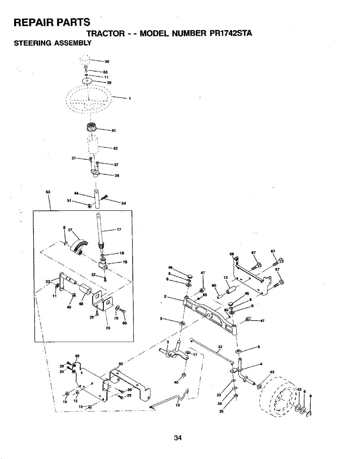
REPAIR PARTS
TRACTOR - - MODEL NUMBER PR1742STA
STEERING ASSEMBLY
62
_41
_:t:t
i_ 42
s
<-
8
40
f17
118
8O
25
15
67
67
43
6
8
34
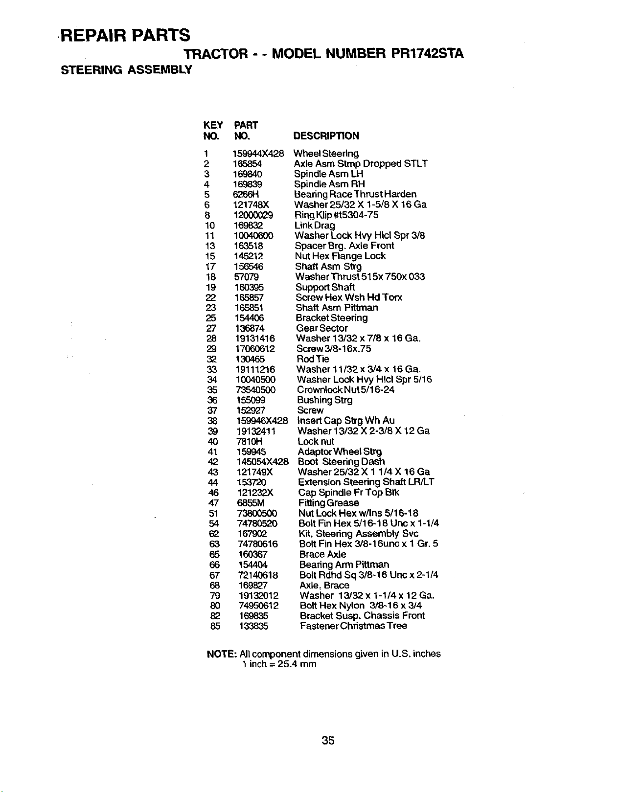
-REPAIR PARTS
TRACTOR - - MODEL NUMBER PR1742STA
STEERING ASSEMBLY
KEY PART
NO. NO, DESCRIP'IION
1 159944X428
2 165854
3 16984O
4 169839
5 6266H
6 121748X
8 120OO029
10 169832
11 10040600
13 163518
15 145212
17 156546
18 57079
19 160395
22 165857
23 165851
25 1544O6
27 136874
28 19131416
29 17060612
32 130465
33 19111216
34 10040500
35 7354O500
36 155O99
37 152927
38 159946X428
39 1913_411
40 7810H
41 159945
42 145054X428
43 121749X
44 153720
46 121232X
47 6855M
51 73800500
54 74780520
62 167902
63 74780616
65 160367
66 154404
67 72140618
68 169827
79 19132012
80 74950612
82 169835
85 133835
Wheel Steering
Axle Asm Stmp Dropped STLT
Spindle Asm LH
Spindle Asm RH
Bearing Race Thrust Harden
Washer 25132 X 1-5/8 X 16 Ga
Ring Klip#t5304-75
LinkDrag
Washer Lock Hvy Hlcl Spr 3/8
Spacer Brg. Axle Front
Nut Hex Flange Lock
Shaft Asm Strg
Washer Thrust 515x 750x 033
Support Shaft
Screw Hex Wsh Hd Torx
Shaft Asm Pittman
Bracket Steering
Gear Sector
Washer 13/32 x 7/8 x 16 Ga.
Screw3/8-16x.75
Rod Tie
Washer 11/32 x 3/4 x 16 Ga.
Washer Lock Hvy HIcl Spr 5/16
CrownlockNut 5/16-24
Bushing Strg
Screw
Insert Cap Strg Wh Au
Washer 13/32 X 2-3/8 X 12 Ga
Lock nut
AdaptorWheel Strg
Boot Steering Dash
Washer 25/32 X 1 1/4 X 16 Ga
Extension Steedng Shaft LR/LT
Cap Spindle Fr Top BIk
FittingGrease
Nut Lock Hex w/Ins 5/16-18
Bolt Fin Hex 5/16-18 Unc x 1-1/4
Kit, Steering Assembly Svc
Bolt Fin Hex 3/8-16unc x 1 Gr. 5
Brace Axle
Bearing Arm Pittman
Bolt Rdhd Sq 3/8-16 Unc x 2-1/4
Axle, Brace
Washer 13/32 x 1-1/4 x t 2 Ga.
Bolt Hex Nylon 3/8-16 x 3/4
Bracket Susp. Chassis Front
Fastener Christmas Tree
NOTE: All component dimensions given in U.S, inches
1 inch = 25.4 mm
35
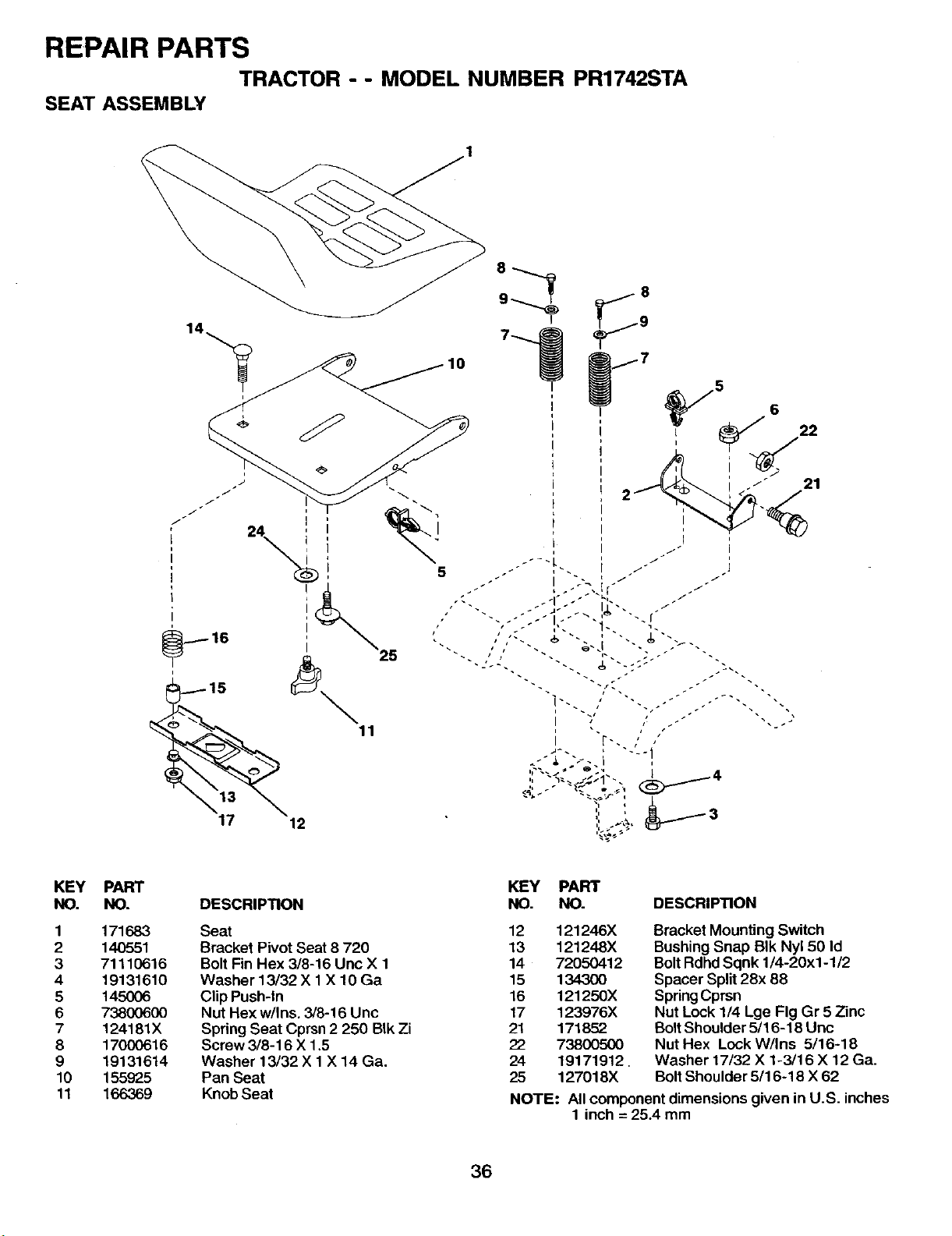
REPAIR PARTS
TRACTOR - - MODEL NUMBER PR1742STA
SEAT ASSEMBLY
KEY
NO.
1
2
3
4
5
6
7
8
9
10
11
PART
NO.
171683
140551
71110616
19131610
145006
73800600
124181X
17000616
19131614
155925
166369
DESCRIPTION
Seat
Bracket Pivot Seat 8 720
Bolt Fin Hex 3/8-16 Unc X 1
Washer 13/32 X 1X 10 Ga
Clip Push-In
Nut Hex w/Ins. 3/8-16 Unc
Spring Seat Cprsn 2 250 BIk Zi
Screw 3/8-16 X 1.5
Washer 13/32 X 1 X 14 Ga.
Pan Seat
Knob Seat
KEY PART
NO. NO. DESCRIPTION
12 121246X
13 121248X
14 72050412
15 134300
16 121250X
17 123976X
21 171852
22 73800500
24 19171912,
25 127018X
Bracket Mounting Switch
Bushing Snap BIk Nyl 50 Id
Bolt Rdhd Sqnk 1/4-20x1-1/2
Spacer Split 28x 88
Spring Cprsn
Nut Lock 1/4 Lge Fig Gr 5 Zinc
Bolt Shoulder 5/16-18 Uric
Nut Hex Lock W/Ins 5/16-18
Washer 17/32 X 1-3/16 X 12 Ga.
Bolt Shoulder 5/16-18 X 62
NOTE: All component dimensions given in U.S. inches
1 inch = 25.4 mm
36
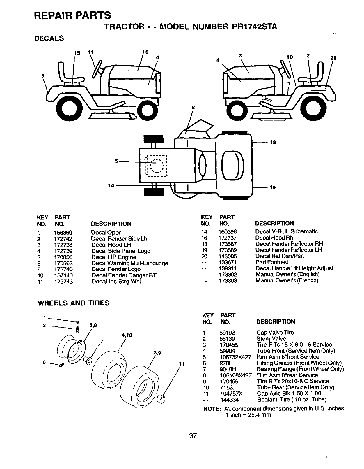
REPAIR PARTS
TRACTOR - - MODEL NUMBER PR1742STA
DECALS
15 11 16
3
9
8
10 2 20
18
14
KEY PART KEY PART
NO. NO. DESCRIPTION NO. NO.
1 156369 DecalOper 14 160396
2 172742 Decal Fender Side Lh 16 172737
3 172738 Decal Hood LH 18 173587
4 172739 Decal Side Panel Logo 19 173589
5 170856 Decal HP Engine 20 145005
8 170563 Decal Warning Mult-Language - - 133671
9 172740 Decal Fender Logo - - 138311
10 157140 Decal Fender Danger FJF -- 173302
11 172743 Decal Ins Strg Whl - - 173303
DESCRIPTION
Decal V-Belt Schematic
Decal Hood Rh
Decal Fender Reflector RH
Decal Fender Reflector LH
Decal Bat DardPsn
Pad Footrest
Decal Handle Lft Height Adjust
Manual Owner's (English)
Manual Owner's (French)
WHEELS AND TIRES
2 _ 5,8
7
4,10
11
KEY PART
NO. NO. DESCRIPTION
1
2
3
4
5
6
7
8
9
10
11
59192
65139
170455
599O4
106732X427
278H
9040H
106108X427
170456
7152J
104757X
144334
Cap Valve Tire
Stem Valve
Tire F Ts 15 X 6 0 - 6 Service
Tube Front (Service Item Only)
Rim Asm 6"trent Service
FittingGrease (Front Wheel Only)
Beanng Flange (Front Wheel Only)
Rim Asm 8"rear Service
Tire R Ts 20x10-8 C Service
Tube Rear (Service Item Only)
Cap Axle BIk 1 50 X 1 00
Sealant, Tire ( 10 oz. Tube)
NOTE: All component dimensions given in U.S. inches
1 inch = 25.4 mm
37
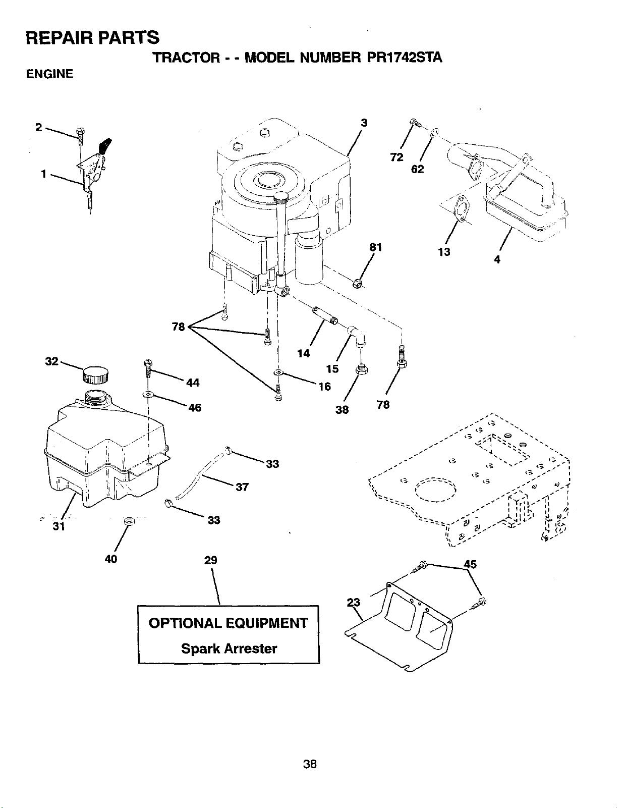
REPAIR pARTS NUMSEP,Pm742s_rA
_c_o_ - - MOOEL
ENG|HF-
31
38
40
3B
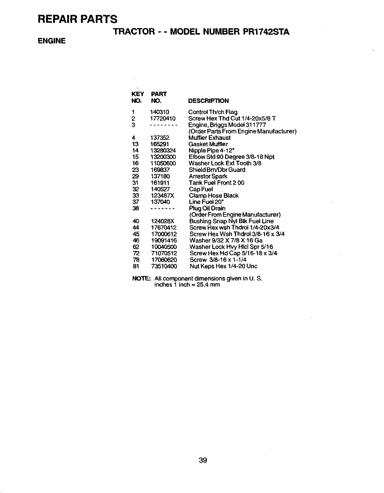
REPAIR PARTS
TRACTOR - - MODEL NUMBER PR1742STA
ENGINE
KEY PART
NO. NO, DESCRIPTION
1
2
3
140310
17720410
4 137352
13 165291
14 13280324
15 132O03OO
16 11050600
23 169837
29 137180
31 161911
32 140527
33 123487X
37 137040
38
40 124028X
44 17670412
45 17000612
46 19091416
62 10040500
72 71070512
78 17060620
81 73510400
Control Th/ch Flag
Screw Hex Thd Cut 1/4-20x5/8 T
Engine, BriggsModel 311777
(Order Parts From Engine Manufacturer)
Muffler Exhaust
Gasket Muffler
Nipple Pipe 4-12"
Elbow Std90 Degree 3/8-18 Npt
Washer Lock Ext Tooth 3/8
Shield Bm/Dbr Guard
ArrestorSpark
Tank Fuel Front 2 00
Cap Fuel
Clamp Hose Black
Line Fuel 20=
PlugOil Drain
(Order From Engine Manufacturer)
Bushing Snap Nyl BIk Fuel Une
Screw Hex wsh Thdrol 1/4-20x3/4
Screw Hex Wsh Thdrol 3/8-16 x 3/4
Washer 9/32 X7/8 X 16 Ga
Washer Lock Hvy Hlcl Spr 5/16
Screw Hex Hd Cap 5/16-18 x 3/4
Screw 3/8-16 x 1-1/4
Nut Keps Hex 1/4-20 Unc
NOTE: All component dimensions given in U. S.
inches 1 inch= 25.4 mm
39
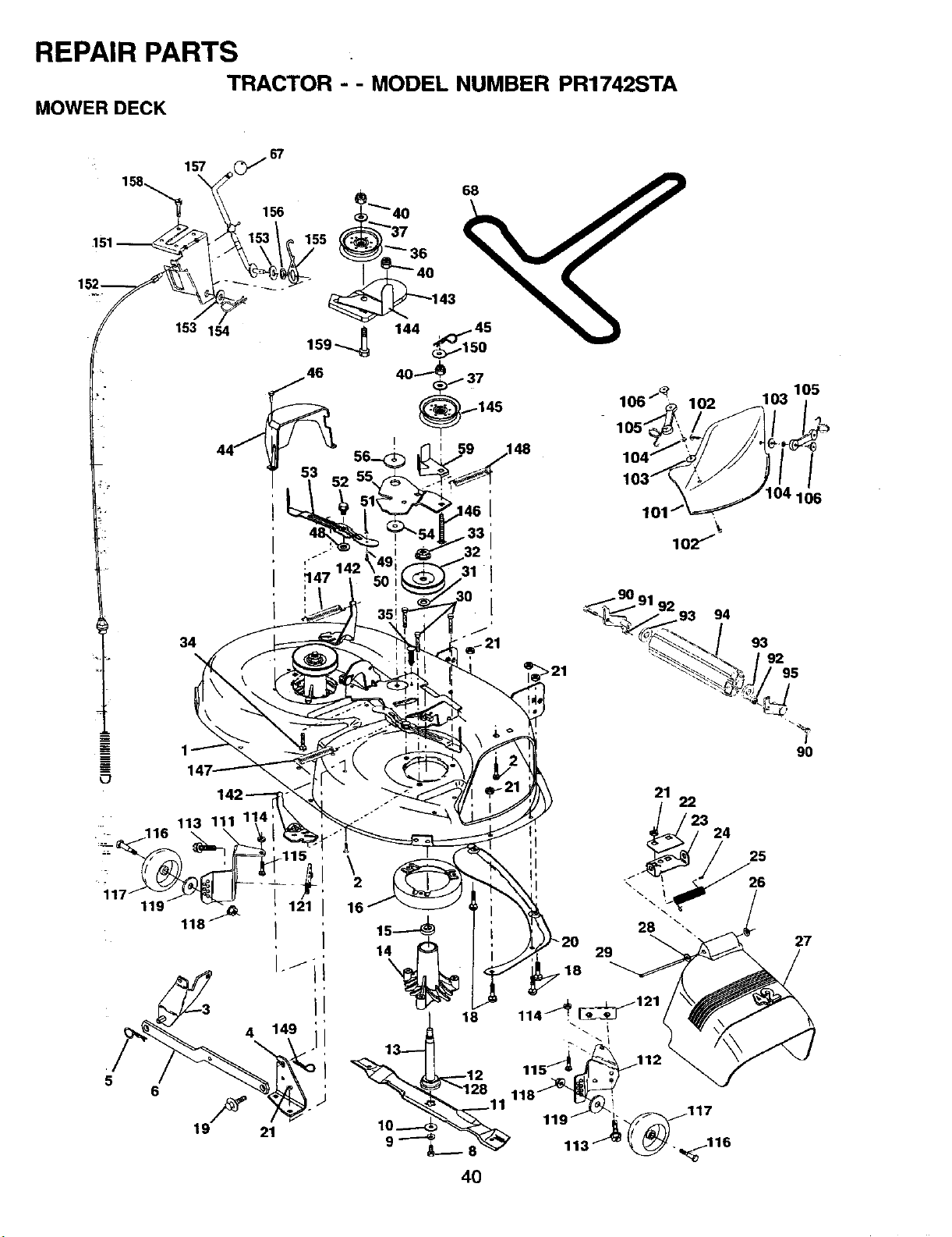
REPAIR PARTS
TRACTOR - - MODEL NUMBER PR1742STA
MOWER DECK
+
157
158,_
153 154
34
106_ 102 103 175
lO2"/
94
93
92
95
119
I
\
2
16
29
"-%
!
90
27
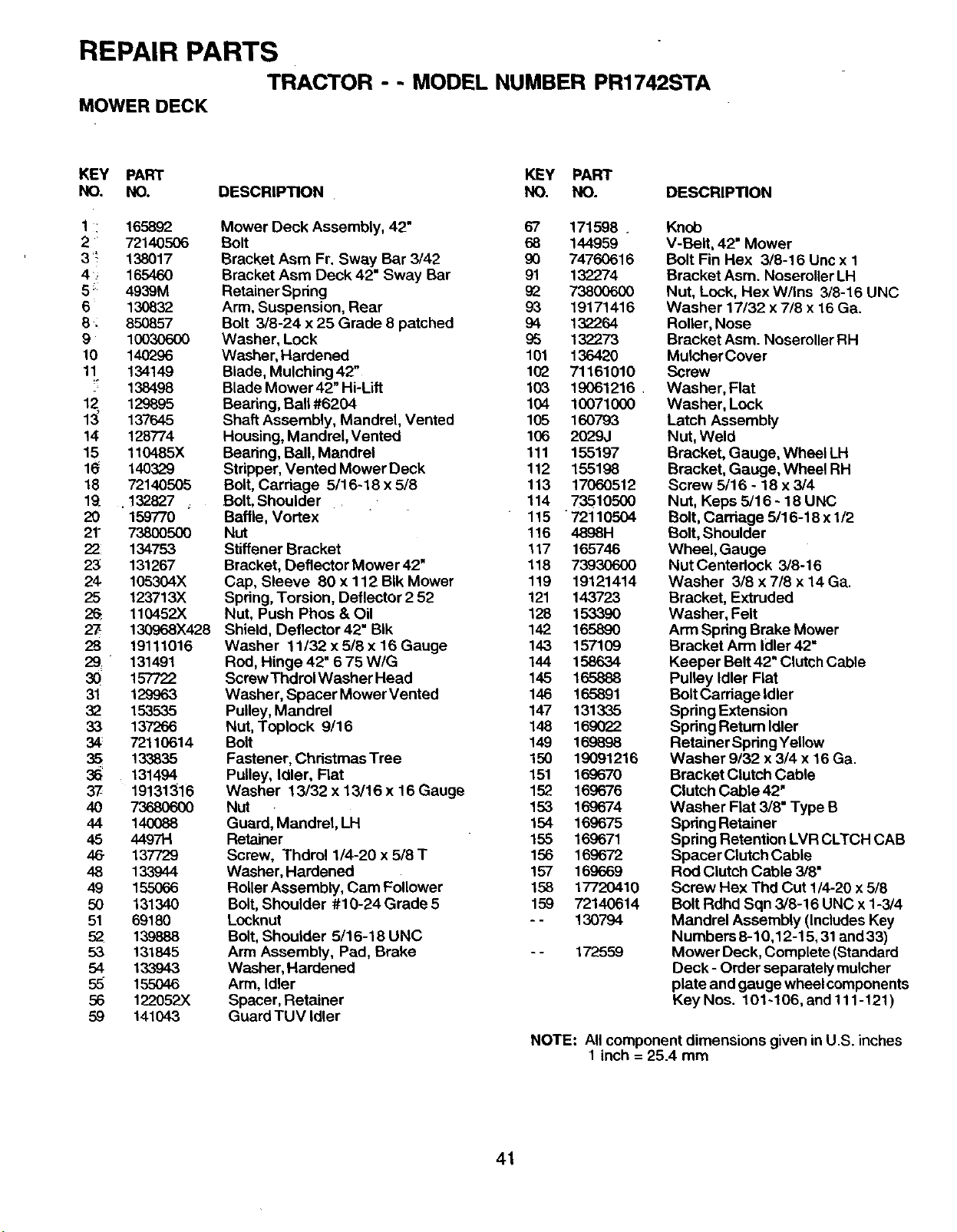
REPAIR PARTS
TRACTOR - - MODEL NUMBER PR1742STA
MOWER DECK
KEY PART KEY PART
NO, NO. DESCRIPTION NO. NO. DESCRIPTION
1 : 165892
2 72140.506
3 _! 138017
4; 165460
5 :: 4939M
6 130832
8 _ 850857
9 10030600
10 140296
11 134149
_" 138498
12 129895
13_ 137645
14 128774
15 110485X
1_ 14O329
18 72140506
19 .132827
20 159770
21° 73800500
22 134753
23 131267
24 105304X
25 123713X
26 110452X
27 130968X428
28 19111016
29_ 131491
30 157722
31 129963
3_ 153535
33 137266
34 72110614
35 133835
36 . 131494
37 19131316
4O 736806OO
44 140088
45 4497H
46 137729
48 133944
49 15.5066
50 131340
51 69180
52 139888
53 131845
54 133943
5.5 155046
56 122052X
59 141043
Mower Deck Assembly, 42" 67 171598 .
Bolt 68 144959
Bracket Asm Fr. Sway Bar 3/42 90 74760616
Bracket Asm Deck 42" Sway Bar 91 132274
RetainerSpdng 9_ 73800600
Arm, Suspension, Rear 93 19171416
Bolt 3/8-24 x 25 Grade 8 patched 94 132264
Washer, Lock £5 132273
Washer, Hardened 101 136420
Blade, Mulching 42" 102 71161010
Blade Mower 42" Hi-Liff 103 19061216 .
Bearing, Ball #6204 104 10071000
Shaft Assembly, Mandrel, Vented 105 160793
Housing, Mandrel, Vented 106 2029J
Bearing, Ball, Mandrel 111 155197
Stripper, Vented Mower Deck 112 155198
Bolt, Cardage 5/16-18 x 5/8 113 17060512
Bolt, Shoulder 114 73510500
Baffle, Vortex 115 72110504
Nut 116 4898H
Stiffener Bracket 117 165746
Bracket, Deflector Mower 42" 118 73930600
Cap, Sleeve 80 x 112 BIk Mower 119 19121414
Spring, Torsion, Deflector 2 52 121 143723
Nut, Push Phos & Oil 128 153390
Shield, Deflector 42" BIk 142 165890
Washer 11/32 x 5/8 x 16 Gauge 143 157109
Rod, Hinge 42" 6 75 WIG 144 158634
Screw Thdrol Washer Head 145 165888
Washer, Spacer Mower Vented 146 165891
Pulley, Mandrel 147 131335
Nut, Toplock 9/16 148 169022
Bolt 149 169898
Fastener, ChdstmasTree 150 19091216
Pulley, Idler, Flat 151 169670
Washer 13/32 x 13/16 x 16 Gauge 152 169676
Nut 153 169674
Guard, Mandrel, LH 154 169675
Retainer 155 169671
Screw, Thdrol 1/4-20x5/8T 156 169672
Washer, Hardened 157 169669
Roller Assembly, Cam Follower 158 17720410
Bolt, Shoulder #10-24Grade5 159 72140614
Locknut - - 130794
Bolt, Shoulder 5/16-18 UNC
Arm Assembly, Pad, Brake - - 172559
Washer, Hardened
Arm, Idler
Spacer, Retainer
Guard TUV Idler
Knob
V-Belt, 42" Mower
Bolt Fin Hex 3/8-16 Unc x 1
Bracket Asm. Noseroller LH
Nut, Lock, Hex W/Ins 3/8-16 UNC
Washer 17/32 x 7/8 x 16 Ga.
Roller, Nose
Bracket Asm. NoseroUer RH
MulcherCover
Screw
Washer, Flat
Washer, Lock
Latch Assembly
Nut, Weld
Bracket, Gauge, Wheel LH
Bracket, Gauge, Wheel RH
Screw 5/16 - 18 x 3/4
Nut, Keps 5/16 - 18 UNC
Bolt, Carriage 5/16-18 x 1/2
Bolt, Shoulder
Wheel, Gauge
Nut Centedock 3/8-16
Washer 3/8 x 7/8 x 14 Ga.
Bracket, Extruded
Washer, Felt
Arm Spdng Brake Mower
Bracket Arm loller42"
Keeper Belt 42" Clutch Cable
Pulley Idler Flat
BoltCardage Idler
Spdng Extension
Spring Return Idler
Retainer Spdng Yellow
Washer 9/32 x 3/4 x 16 Ga.
Bracket Clutch Cable
Clutch Cable 42"
Washer Flat 3/8" Type B
Spdng Retainer
Spring Retention LVR CLTCH CAB
Spacer Clutch Cable
Rod Clutch Cable 3/8=
Screw Hex Thd Cut 1/4-20 x 5/8
Bolt Rdhd Sqn 3/8-16 UNC x 1-3/4
Mandrel Assembly (Includes Key
Numbers 8-10,12-15, 31 and 33)
Mower Deck, Complete (Standard
Deck- Order separately mulcher
plate and gauge wheel components
Key Nos. 101-106, and 111-121 )
NOTE: All component dimensions given in U.S. inches
1 inch = 25.4 mm
41
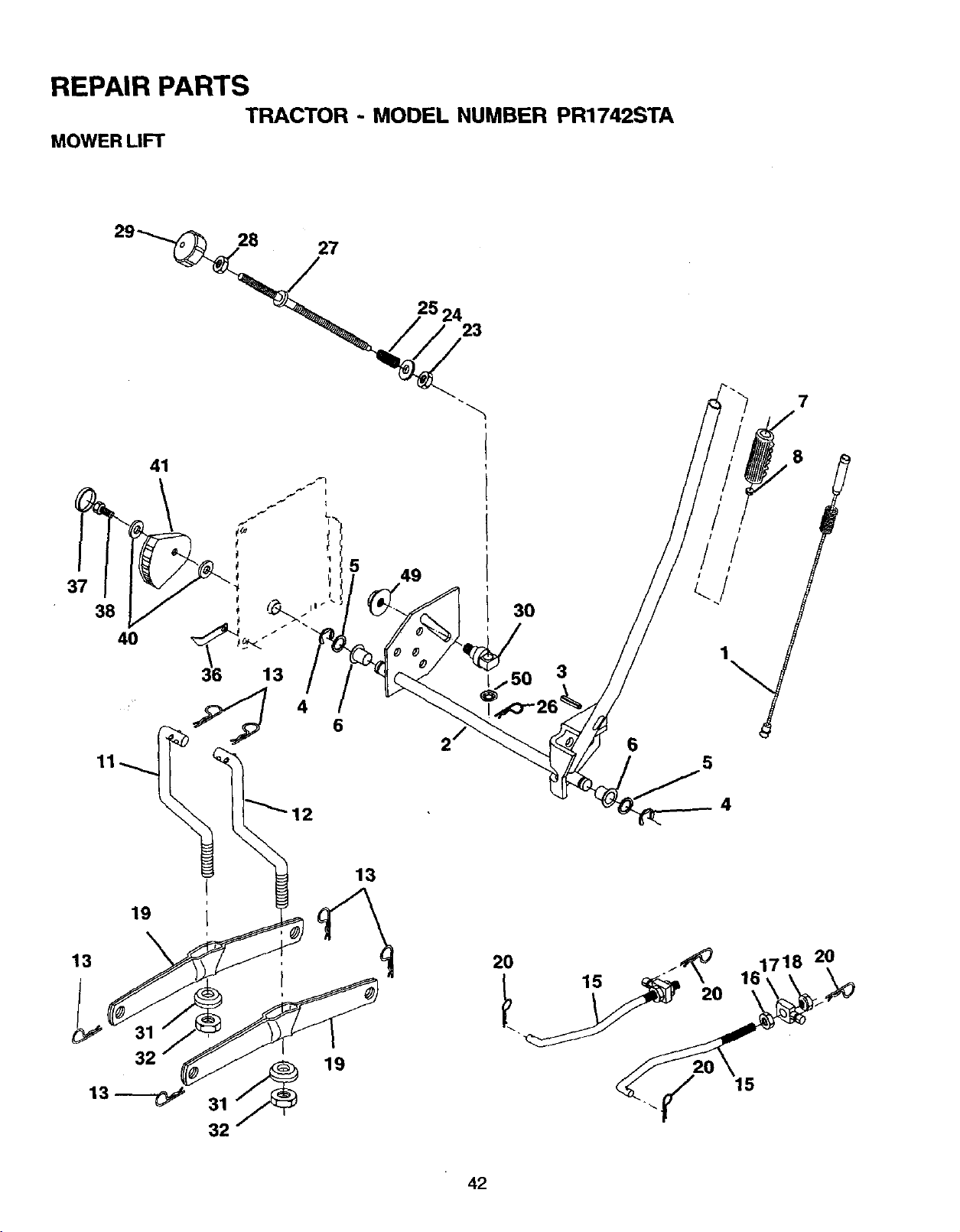
REPAIR PARTS
TRACTOR - MODEL NUMBER PR1742STA
MOWER LIFT
29_
26
27
25 24
23
7
41
_" LI"_
36 13
4 6
11
I
19 L
13
49
13
3O
20
6
15
1
5
4
./'_ 161718 20
2O
42
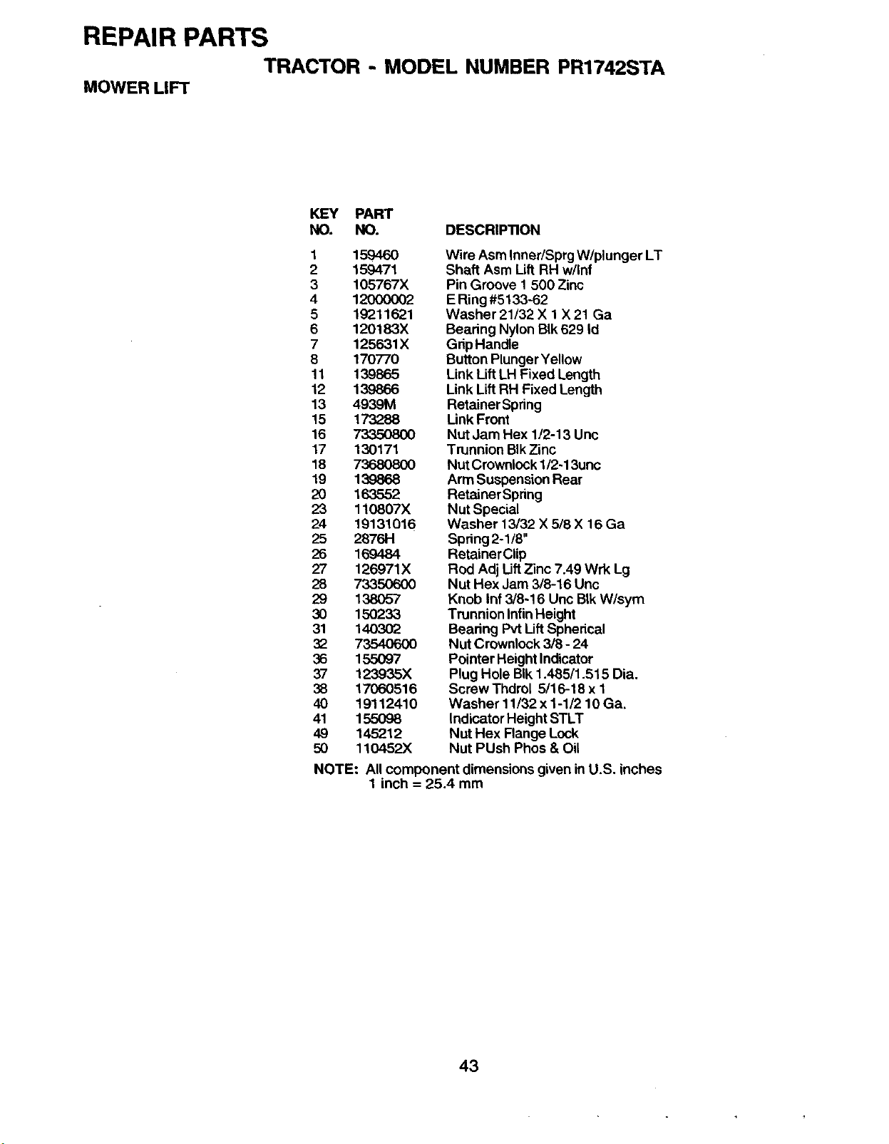
REPAIR PARTS
TRACTOR - MODEL NUMBER PR1742STA
MOWER LIFT
KEY PART
NO. NO. DESCRIPTION
1 159460
2 159471
3 105767X
4 12000002
5 19211621
6 120183X
7 125631X
8 170770
11 139865
12 139866
13 4939M
15 173288
16 7335O800
17 130171
18 73680800
19 139868
20 163552
23 110807X
24 19131016
25 28761-1
26 169484
27 126971X
28 73350600
29 138O57
30 150233
31 140302
32 7354O6OO
36 155097
37 123935X
38 17060516
40 19112410
41 155098
49 145212
50 110452.)(
Wire Asm Inner/Sprg W/plunger LT
Shaft Asm Lift RH w/Inf
Pin Groove 1 500 Zinc
E Ring #5133-62
Washer 21/32 X 1 X 21 Ga
Bearing Nylon BIk 629 Id
GripHandle
Button Plunger Yellow
Link Lift LH Fixed Length
Link Lift RH Fixed Length
Retainer Spring
Link Front
Nut Jam Hex 1/2-13 Unc
Trunnion BIk Zinc
Nut Crownlock 1/2-13unc
Arm Suspension Rear
Retainer Spring
Nut Special
Washer 13/32 X 5/8 X 16 Ga
Spring2-1/8"
Retainer Clip
Rod Adj LiftZinc 7.49 Wrk Lg
Nut Hex Jam 3/8-16 Unc
Knob Inf 3/8-16 Unc BIk W/sym
Trunnion InfinHeight
Bearing Pvt LiftSpherical
Nut Crownlock 3/8 - 24
Pointer Height Indicator
Plug Hole BIk1.485/1.515 Dia.
ScrewThdml 5/16-18 x 1
Washer 11/32 x 1-1/2 10 Ga.
Indicator Height STLT
Nut Hex Flange Lock
Nut PUsh Phos & Oil
NOTE: All component dimensions given in U.S. inches
1 inch = 25.4 mm
43

NOTES
44
LIMITED WARRANTY
The Manufacturer warrants to the original consumer purchaser that this product as manufactured is free from defects in
materials and workmanship. For a period of two (2) years from date of purchase by the original consumer purchaser, we will
repair or replace, at our option, without charge for paris or labor incurred in replacing parts, any part which we find to be
defective due to materials or workmanship. This Warranty is subject to the following limitations and exclusions.
1. This warranty does not apply to the engine, other than FHP manufactured transaxle/transmission components, battery
(except as noted below) or components parts thereof. Please refer to the applicable manufacturer's warranty on these
items.
2. Transportation charges for the movement of any power equipment unit or attachment are the responsibility of the
purchaser. Transportation charges for any parts submitted for replacement under this warranty must be paid by the
purchaser unless such return is requested by Frigidaire Home Products.
3. Battery Warranty: On products equipped with a Battery, we will replace, without charge to you, any battery which we find
to be defective in manufacture, during the first ninety (90) days of ownership. After ninety (90) days, we will exchange
the Battery, charging you 1/12 of the price of a new Battery for each full month from the date of the original sale. Battery
must be maintained in accordance with the iostruofions furnished.
4.
5.
6.
7.
The Warranty period for any products used for rental or commercial purposes is limited to 90 days from the date of
original purchase.
This Warranty applies only to products which have been property assembled, adjusted, operated, and maintained in
accordance with the instructions fumisbed. This Warranty does not apply to any product which has been subjected to
alteration, misuse, abuse, improper assembly or installation, delivery damage, or to normal wear of the product.
Exclusions: Excluded from this Warranty are belts, blades, blade adapters, normal wear, normal adjustments, standard
hardware and normal maintenance.
In the event you have a claim under this Warranty, you must return the product to an authorized seTvice dealer.
Should you have any unanswered questions concerning this Warranty, please contact:
Frigidaire Home Products
Outdoor Products Customer Service Dept.
250 Bobby Jones Expressway
Augusta, GA 30909 USA
In Canada contact:
Frigidaire Home Products
7075 Ordan Drive
• Missiaseuga, Ontario
L5T 1K6
giving the model number, serial number and date of purchase of your product and the name and address of the authorized
dealer from whom it was purchased.
THIS WARRANTY DOES NOT APPLY TO INCIDENTAL OR CONSEQUENTIAL DAMAGES AND ANY IMPLIED WARRAN-
TIES ARE LIMITED TO THE SAME TIME PERIODS STATED HEREIN FOR OUR EXPRESSED WARRANTIES. Some areas
do not allow the limitation of consequential damages or limitations of how long an implied Warranty may last, so the above
limitations or exclusions may not apply to you. This Warranty gives you specific legal rights, and you may have other rights
which vary from locale to locale.
This is a limited Warranty within the meaning of that term as defined in the Magnoson-Moss Act of 1975.
/
45

WARRANTY
Issued January 1980
Revised January 1991
LIMITED WARRANTIES
FOR
NEW PEERLESS GEAR POWER TRAIN COMPONENTS
A. Products Warranted
Peerless Gear and Machine Division of Tecumseh Products Company ('l'ecumseh"), subject to the limitations contained below,
wiU,at its option, repair or replace, without charge for parts or labor only, any part of a new Power Train Component (which as used herein
means and includes thetransaxle, gear box, transmission, differential and rightangle drives,and any part ofthe Power Train Component),
EXCEPT any new Power Train Component incorporated in equipment used for commercial or rental purposes, which is found upon
examination byanyTecumseh Authorized Sewice Outlet or byTecumseh's factory inG raffon,Wisconsin, tobe DEFECTIVE iN MATERIAL
AND/OR WORKMANSHIP if received byTecumseh or a Tecumseh Authorized Service Outlet forsuch examination within TWO YEARS
from the date of sale to the original consumer purchaser of Peerless Series 820, 900, 910, 915, 920, 930 transaxles and Series 1100
angle drive and ONE YEAR for all other Peerless products. New Power Train Components incorporated in equipment used for
commercial purposes are warranted in the same manner and to the same extent EXCEPT such Power Train Components are warranted
for NINETY (90) DAYS ONLY, and must be received by Tecumseh or by a Tecumseh Authorized Service Outlet for such examination
within 90 days from the date of sale to the original purchaser. New Power Train Components Incorporated in equipment used for rental
purposes are warranted in the same manner and to the same extent EXCEPT such Power Train Components are warranted for THIRTY
(30) DAYS ONLY, and must be received by Tecumseh or a Tecumseh Authorized Service Outlet within 30 days from the date of sale
to the original purchaser.
B. Products And Items Not Warranted
1. Alterations or Modifications of Power Train Components.
2. Accidents, Normal Maintenance, Failure to follow the Original Equipment Manufacturer's Manual.
This warranty covers only parts of new Power Train Components which are found uponexamination to be defective in material or
workmanship as delivered to the original purchaser. This warranty does notcover detects caused by depreciation or damage caused
by normal wear, accidents, improper maintenance, improper use or abuse of the product, failure tofollow the instructions contained in
an Instruction Manual for the operation of the Power Train Component and parts. The cost of normal maintenance and replacement
of service items which are not defective shall be paid for by the original purchaser.
C. SecurinQ Warranty Service
Warranty service can be arranged for by contacting either a Tecumseh Authorized Service Outlet (any Tecumseh Registered Service
Dealer, Tecumseh Authorized Service Distributor, or Tecumseh Central Warehouse Distributor)or by contacting Tecumseh, c/o Service
Manager, Engine and Transmission Group Service Divisien_ 900 North Street, Grafton, Wisconsin 53024. Warranty service can only
be performed by a Tecumseh Authorized Service Outlet or by Tecumseh at its factory in Graften, Wisconsin. At the time of requesting
warranty service, evidence must be presented of the date of sale to the original purchaser. The purchaser shall pay any charges for
making service calls and!or for transporting the product to and from the place where the inspection and/or warranty work is performed.
The purchaser shall be responsible for any damage or loss incurred in connection with the transportation of Power Train Components
and/or part(s) of the Power Train Components submitted for inspection and/or warranty work.
D. Limitation of Damages and Implied Warranties
The foregoing EXPRESSED WARRANTY iS IN LiEU OF ALL OTHER EXPRESS WARRANTIES. Neither Tecumseh nor any of its
affiliates makes any warranties, representations or promises, written or oral, as to the quality of the Power Train Component or any of
its parts, other than as set forth herein.
ANY IMPLIED WARRANTY OF MERCHANTABILITY OR FITNESS FOR A PARTICULAR PURPOSE, TO THE EXTENT THAT
EITHER MAY APPLY TO ANY PART(S) OF POWER TRAIN COMPONENTS, SHALL BE LIMITED IN DURATION TO THE PERIODS OF
THE EXPRESSED WARRANTIES DEFINED IN PARAGRAPH A HEREOF. IN NO EVENT WILL TECUMSEH BE LIABLE FOR ANY
iNCIDENTAL, CONSEQUENTIAL OR SPECIAL DAMAGES AND/OR EXPENSES. Some states do not allow limitations on how long
an implied warranty lastsor the exclusion or limitation of incidental or consequential damages, so the above limitation(s) or exclusion(s)
may not apply to you. This warranty gives you specific legal rights and you may also have other legal rights which vary from state to
state.
E. No DealerWarranty
Tecumseh neither assumes nor authorizes any other person, natural or corporate, toassume for Tecumseh any other obligations
or liabilities in connection with or with respect to any part(s) of a Power Train Component. The seUer or dealer of part(s) of a Power Train
Component has no authority, whatsoever, to make any representations or promises on behalf of Tecumseh or to modify the terms or
limitations of Tecumseh's warranty in any way.
46

SUGGESTED GUIDE FOR SIGHTING SLOPES FOR SAFE OPERATION
.,,,,,,
I "'" "-.-.
SIGHTING "- *....CUT
GUIDE TH"_
ONLY RIDE UP AND DOWN HILL,
NOT ACROSS HILL
SIGHT AND HOLD THIS LEVEL WITH
SKY LINE OR TREE.
150MAX.
!
Operate your Tractor up and down the face of slopes (not ]
greater than 15°), never across the face. Make turns gradu-
I
ally to prevent tipping or !ose of control. Exercise extreme
caution when changing direction on slopes.
Illll II
PARTS AND SERVICE
Your POULAN PRO product has been expertly engineered and carefully manufactured to rigid
quality standards. As with all mechanical products, some adjustments or part replacement may be
necessary during the life of your unit.
FOR SERVICE OR REPLACEMENT PARTS:
1. Consult your dealer/place of purchase.
2. Consult the yellow pages of your phone directory for the name of the nearest service dealer
(under "saws" for Chain Saws or under "lawn mowers" for Trimmers, Brushcutters, and
Blowers).
3. For replacement parts, have available the following information:
a. ModelNumber/Manufacturer's I.D. Number
b. Description of part.
NOTE:
Frigidaire Home Products provides parts and service through its authorized distribu-
tors and dealers; therefore, all re_tuests for parts and service should be directed to your
local dealer(s). The philosophy of Frigidaire Home Products is to continually improve
all of its products. If the operating characteristics orthe appearance of your product
differs from those described in this Manual, please contact your local dealer for updated
information and assistance.