
Loading ...
Loading ...
Loading ...
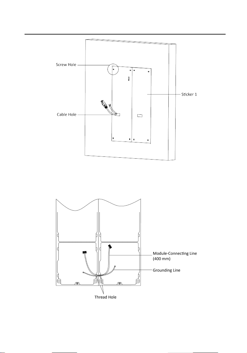
Figure 2-45 Drill Screw Holes
4.
Remove the sckers and insert the expansion sleeves into the screw holes.
5.
Thread the module-connecng line (400 mm) and grounding line across the
thread hole of both frames.
Figure 2-46 Place the Grounding Line and Module-Connecng Line
Module Door Staon User Manual
40
Loading ...
Loading ...
Loading ...