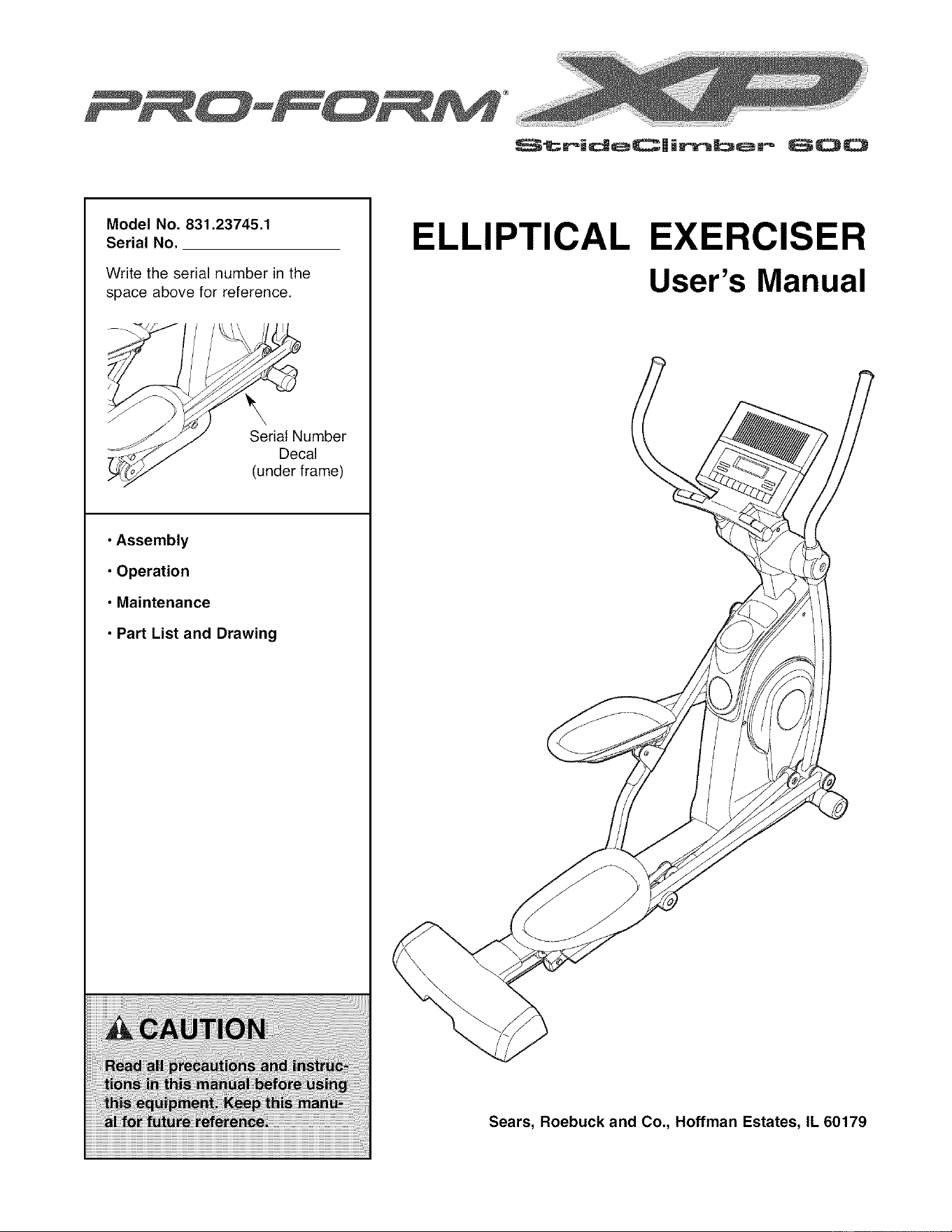
ModelNo,831.23745.1
SerialNo,
Write the serial number in the
space above for reference.
_umber
Decal
(under frame)
• Assembly
• Operation
• Maintenance
• Part List and Drawing
ELLIPTICAL EXERCISER
User's Manual
Sears, Roebuck and Co., Hoffman Estates, IL 60179
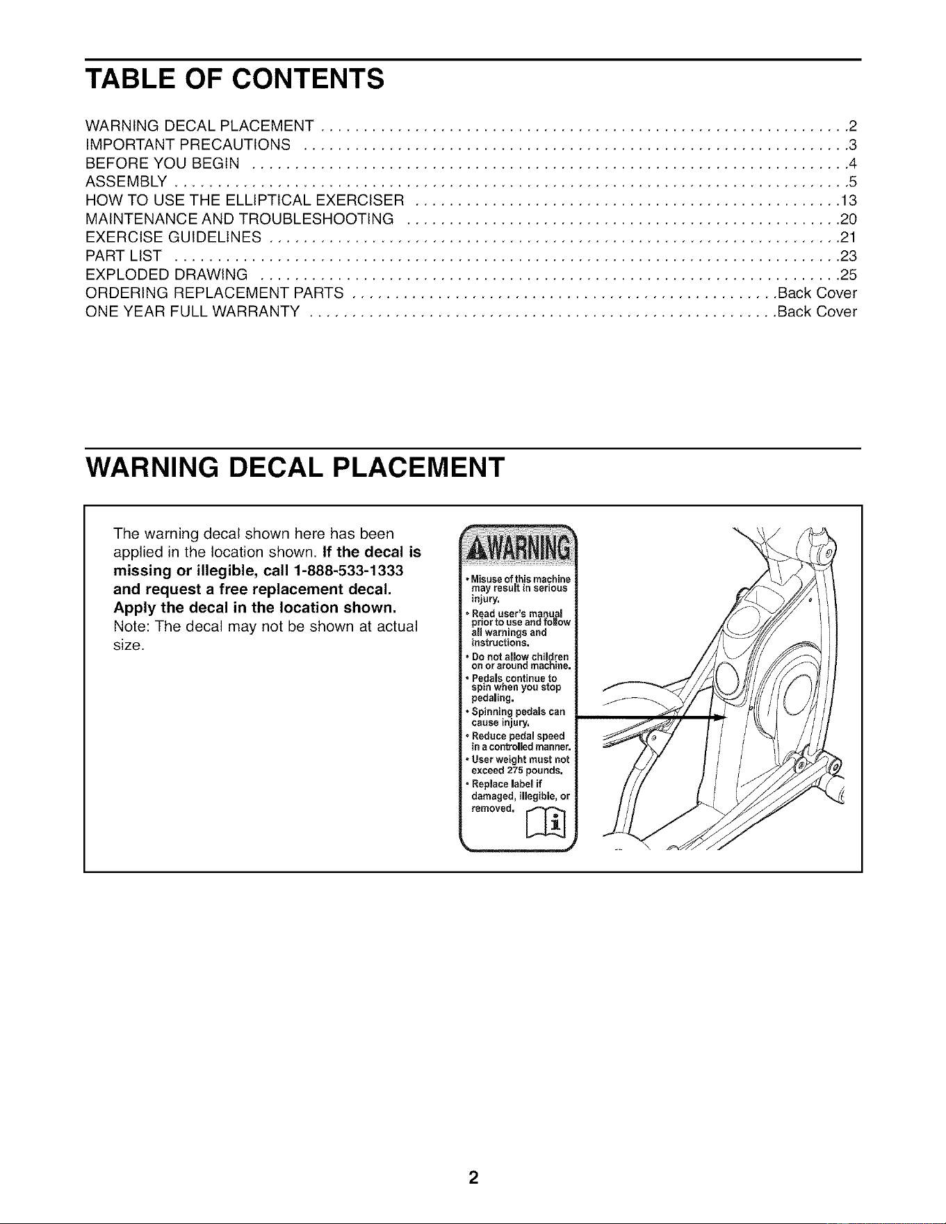
TABLE OF CONTENTS
WARNING DECAL PLACEMENT .............................................................. 2
IMPORTANT PRECAUTIONS ................................................................ 3
BEFORE YOU BEGIN ...................................................................... 4
ASSEMBLY ............................................................................... 5
HOW TO USE THE ELLIPTICAL EXERCISER .................................................. 13
MAINTENANCE AND TROUBLESHOOTING ................................................... 20
EXERCISE GUIDELINES ................................................................... 21
PART LIST .............................................................................. 23
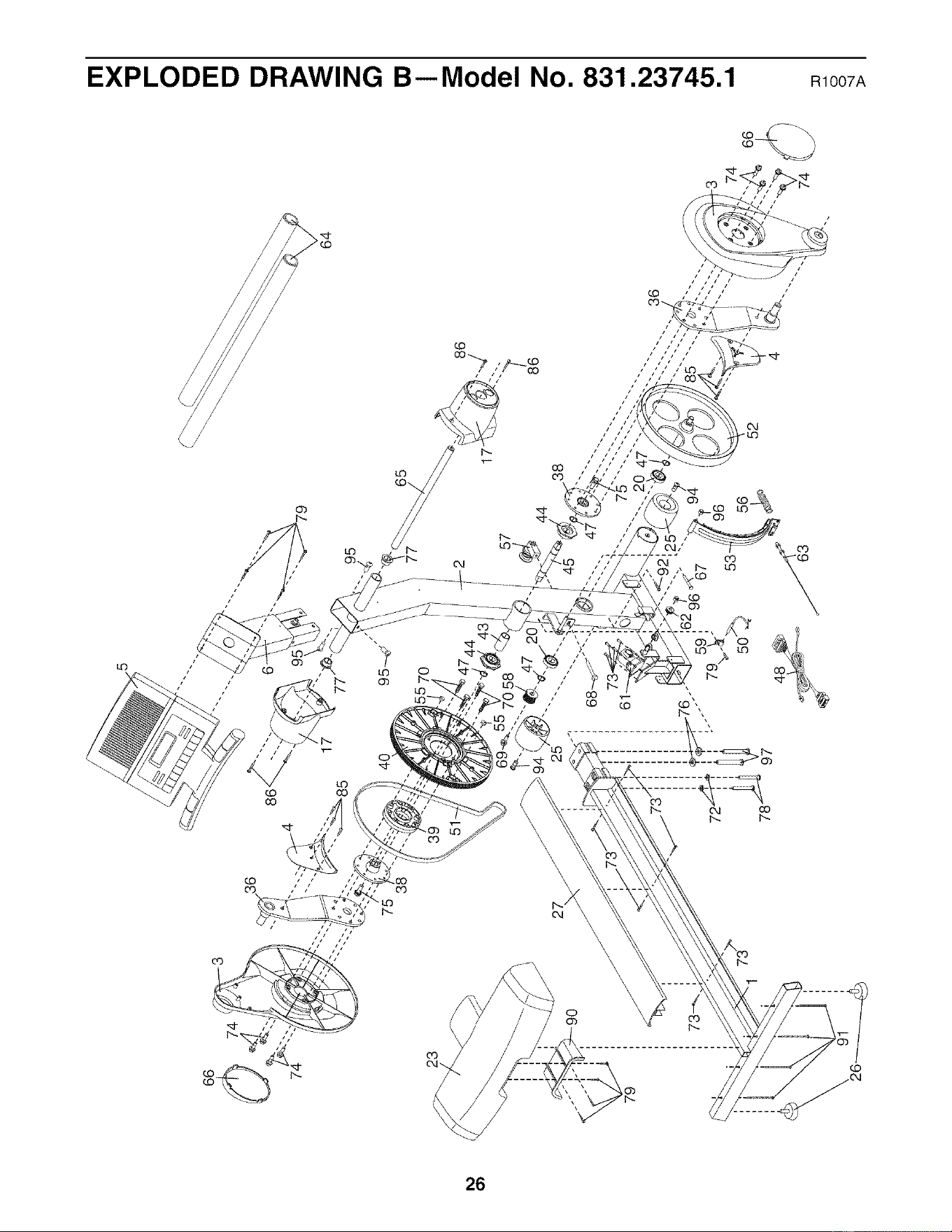
EXPLODED DRAWING .................................................................... 25
ORDERING REPLACEMENT PARTS .................................................. Back Cover
ONE YEAR FULL WARRANTY ....................................................... Back Cover
WARNING DECAL PLACEMENT
The warning decal shown here has been
applied in the location shown. If the decal is
missing or illegible, call 1-888-533-1333
and request a free replacement decal.
Apply the decal in the location shown.
Note: The decal may not be shown at actual
size,
*Misuse ofthis machine
may result in serious
injury.
oRead user's manua
prior to use and follow
all warnings and
instructions.
* Do not allow children
on or around machine,
. Pedals continue to
spin when you stop
pedaling.
* Spinning pedals can
cause injury,
. Reduce pedal speed
ina controlledmanner.
- User weight must not
exceed 275 pounds.
, Replace label if
damaged, illegible, or
removed. _
2
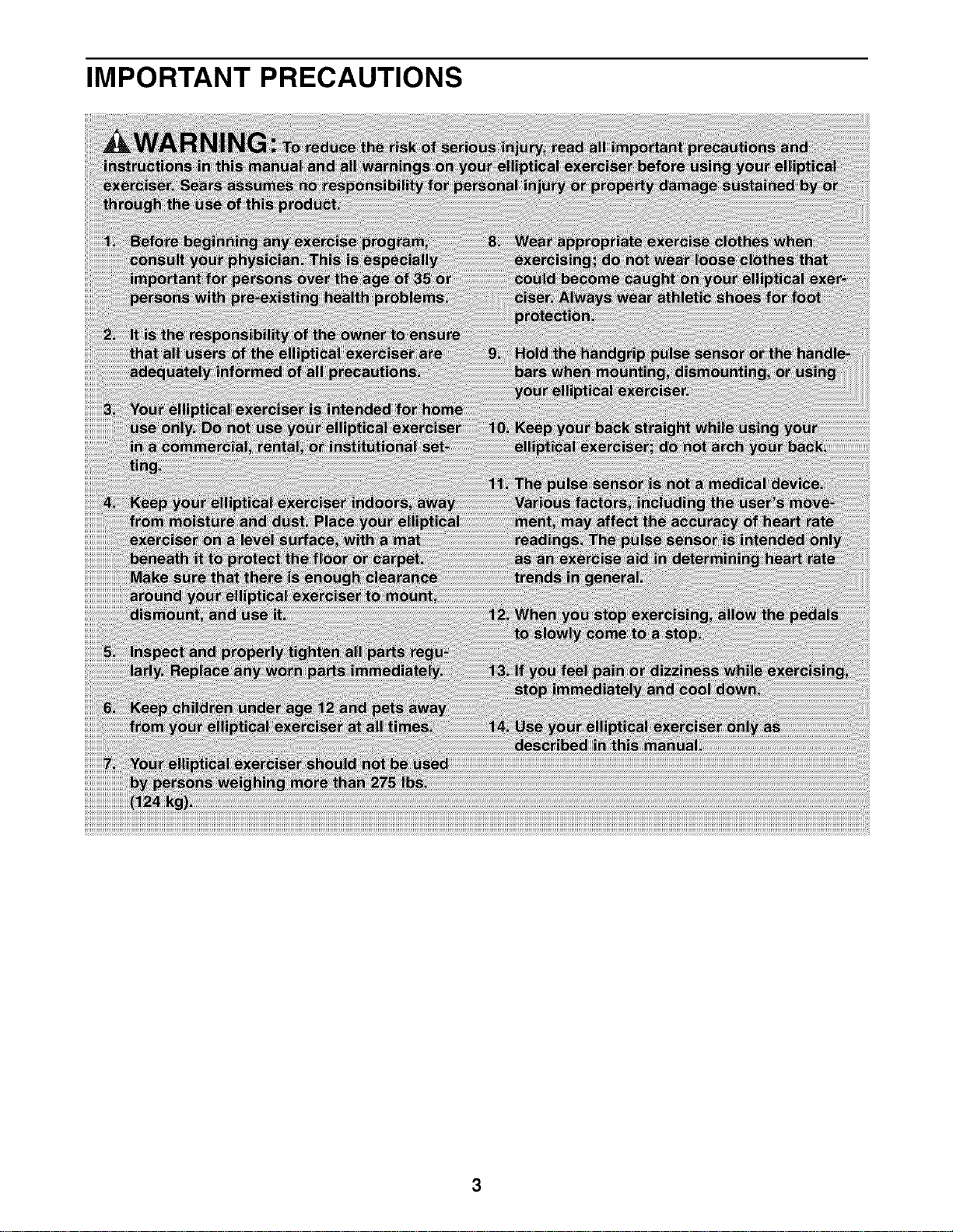
IMPORTANT PRECAUTIONS
BEFORE YOU BEGIN
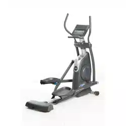
Thank you for selecting the revolutionary PROFORM _
XP STRIDECLIMBER 600 elliptical exerciser. The XP
STRIDECLIMBER 600 elliptical exerciser provides a
wide array of features designed to make your work-
outs at home more effective and enjoyable.
For your benefit, read this manual carefully before
you use the elliptical exerciser, If you have ques-
tions after reading this manual, please see the back
cover of this manual. To help us assist you, note the
product model number and serial number before con-
tacting us. The model number and the location of the
serial number decal are shown on the front cover of
this manual.
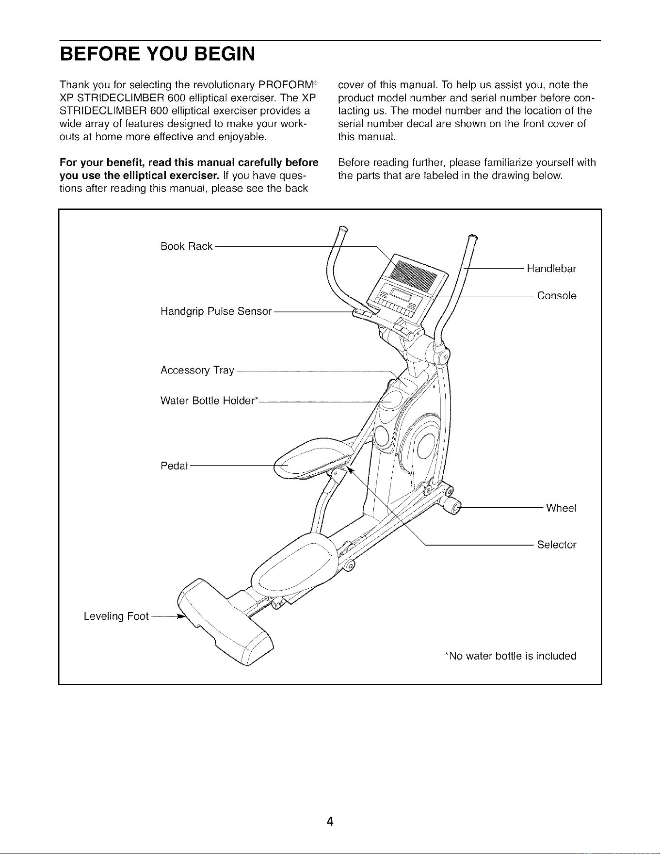
Before reading further, please familiarize yourself with
the parts that are labeled in the drawing below.
Book Rack
Handgrip Pulse Sensor
Handlebar
Console
Accessory Tray
Water Bottle Holder*
Pedal
Wheel
Selector
Leveling Foc
*No water bottle is included
4
ASSEMBLY
Assembly requires two persons, Place all parts of the elliptical exerciser in a cleared area and remove the
packing materials. Do not dispose of the packing materials until assembly is completed. In addition to the
included hex keys, assembly requires a Phillips screwdriver _, an adjustable
wrench _, and a rubber mallet c
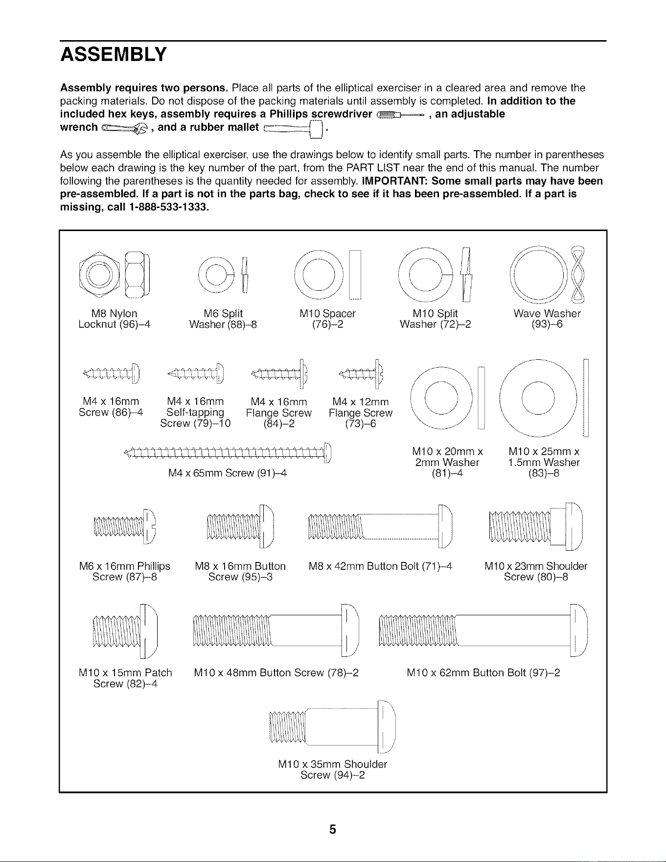
As you assemble the elliptical exerciser, use the drawings below to identify small parts. The number in parentheses
below each drawing is the key number of the part, from the PART LIST near the end of this manual. The number
following the parentheses is the quantity needed for assembly. IMPORTANT: Some small parts may have been
pre-assembled. If a part is not in the parts bag, check to see if it has been pre-assembled. If a part is
missing, call 1-888-533-1333.
M8 Nylon
Locknut (96)-4
M6 Split M10 Spacer M10 Split Wave Washer
Washer (88)-8 (76)-2 Washer (72)-2 (93)-6
M4 x 16mm
Screw (86)-4
M4 x 16mm M4 x 16mm M4 x 12mm
Self-tapping Flange Screw Flange Screw
Screw (79)-10 (84)-2 (73)-6
M4 x 65mm Screw (91)-4
\
M10 x 20mm x M10 x 25mm x
2mm Washer 1.5mm Washer
(81)-4 (83)-8
M6 x 16mm Phillips
Screw (87)-8
M8 x 16mm Button
Screw (95)-3
M8 x 42mm Button Bolt (71)-4
MIO x 23mm Shoulder
Screw (80)-8
MIO x 15mm Patch
Screw (82)-4
M10 x 48mm Button Screw (78)-2 M10 x 62mm Button Bolt (97)-2
M10 x 35mm Shoulder
Screw (94)-2
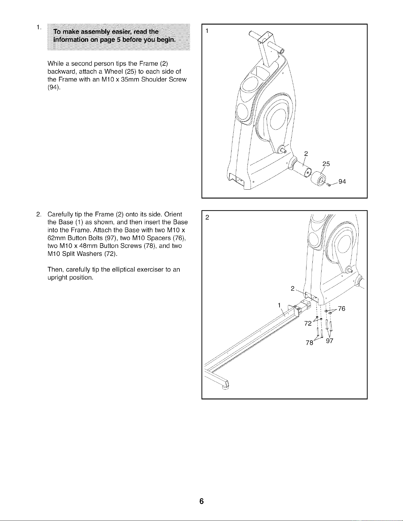
WhileasecondpersontipstheFrame(2)
backward,attachaWheel(25)to eachsideof
theFramewithanMIOx 35mmShoulderScrew
(94).
25
CarefullytiptheFrame(2)ontoitsside.Orient
theBase(1)asshown,andtheninserttheBase
intotheFrame.AttachtheBasewithtwoMIOx
62mmButtonBolts(97),twoMIOSpacers(76),
twoMIOx 48mmButtonScrews(78),andtwo
MIOSplitWashers(72).
Then,carefullytiptheellipticalexercisertoan
uprightposition.
6
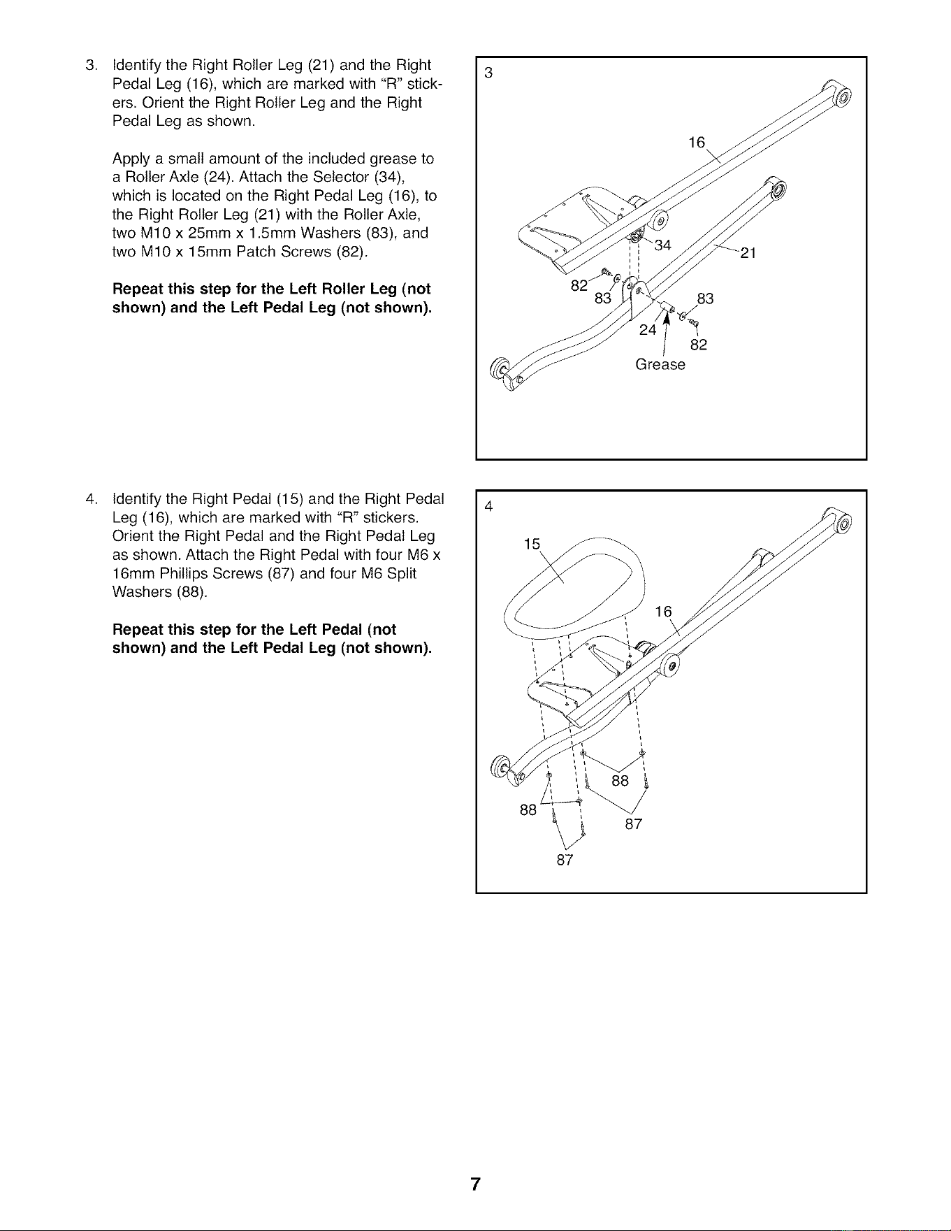
3. 3
Identify the Right Roller Leg (21) and the Right
Pedal Leg (16), which are marked with "R" stick-
ers. Orient the Right Roller Leg and the Right
Pedal Leg as shown.
Apply a small amount of the included grease to
a Roller Axle (24). Attach the Selector (34),
which is located on the Right Pedal Leg (16), to
the Right Roller Leg (21) with the Roller Axle,
two M10 x 25mm x 1.5mm Washers (83), and
two M10 x 15mm Patch Screws (82).
Repeat this step for the Left Roller Leg (not
shown) and the Left Pedal Leg (not shown),
16
83 83
82
Grease
4,
Identify the Right Pedal (15) and the Right Pedal
Leg (16), which are marked with "R" stickers.
Orient the Right Pedal and the Right Pedal Leg
as shown. Attach the Right Pedal with four M6 x
16mm Phillips Screws (87) and four M6 Split
Washers (88).
Repeat this step for the Left Pedal (not
shown) and the Left Pedal Leg (not shown),
88 _ 87
87
16
7
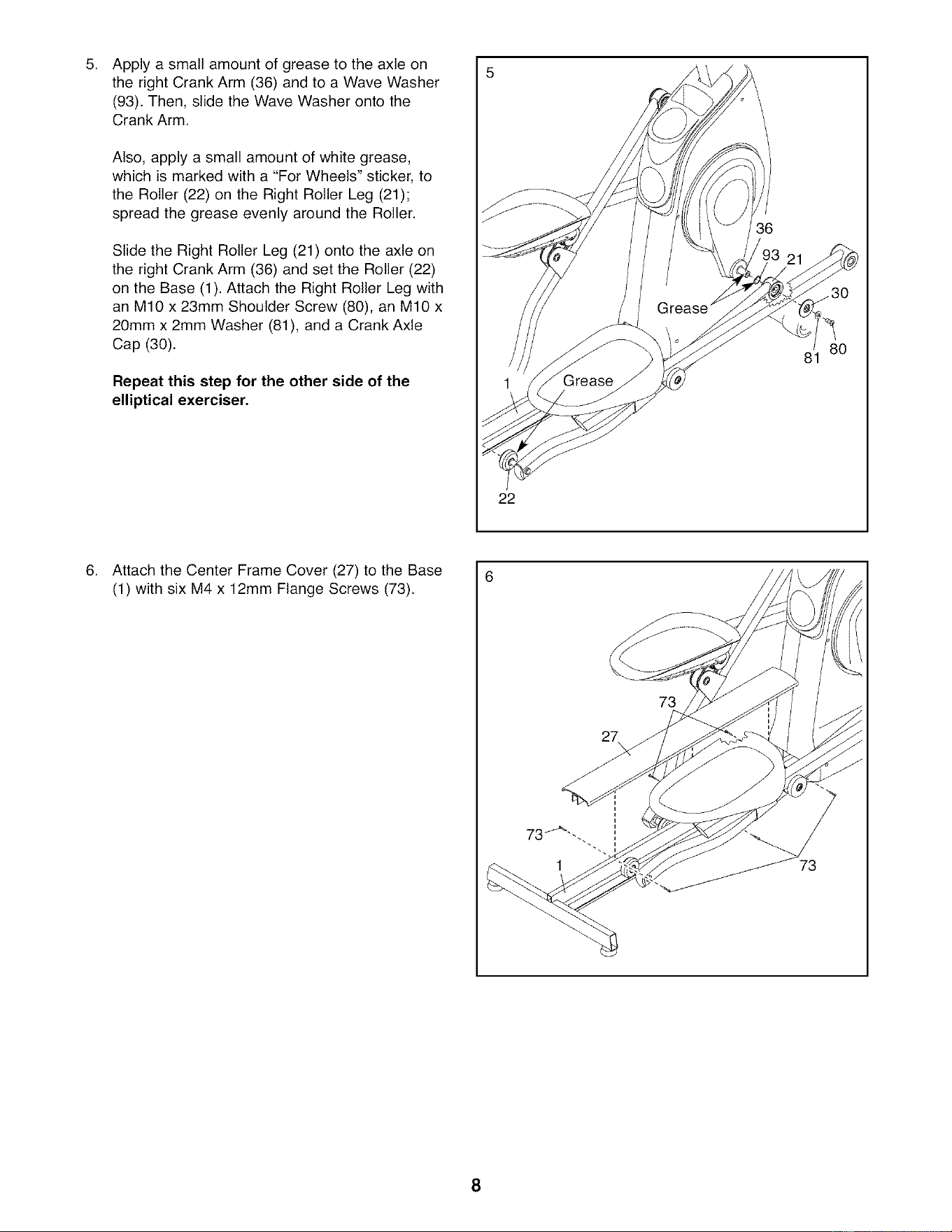
Apply a small amount of grease to the axle on
the right Crank Arm (36) and to a Wave Washer
(93). Then, slide the Wave Washer onto the
Crank Arm.
Also, apply a small amount of white grease,
which is marked with a "For Wheels" sticker, to
the Roller (22) on the Right Roller Leg (21);
spread the grease evenly around the Roller.
Slide the Right Roller Leg (21) onto the axle on
the right Crank Arm (36) and set the Roller (22)
on the Base (1). Attach the Right Roller Leg with
an M10 x 23mm Shoulder Screw (80), an M10 x
20mm x 2mm Washer (81), and a Crank Axle
Cap (30).
Repeat this step for the other side of the
elliptical exerciser.
22
36
81
,
Attach the Center Frame Cover (27) to the Base
(1) with six M4 x 12mm Flange Screws (73).
73
73
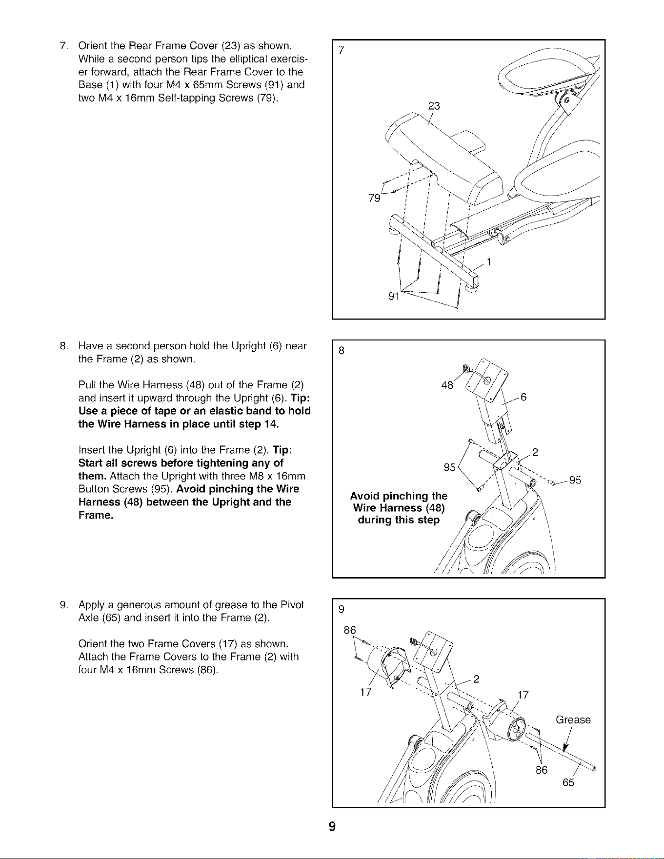
7. 7
OrienttheRearFrameCover(23)asshown.
Whilea secondpersontipstheellipticalexercis-
erforward,attachtheRearFrameCovertothe
Base(1)withfourM4x65mmScrews(91)and
twoM4x 16mmSelf-tappingScrews(79).
23
79
HaveasecondpersonholdtheUpright(6)near
theFrame(2)asshown.
PulltheWireHarness(48)outof theFrame(2)
andinsertit upwardthroughtheUpright(6).Tip:
Usea pieceof tapeor anelasticbandto hold
theWireHarnessin placeuntil step14.
InserttheUpright(6)intotheFrame(2).Tip:
Startall screwsbeforetighteninganyof
them.AttachtheUprightwiththreeM8x 16mm
ButtonScrews(95).AvoidpinchingtheWire
Harness(48)betweentheUprightandthe
Frame.
Avoid pinching the
Wire Harness (48)
during this step
.
Apply a generous amount of grease to the Pivot
Axle (65) and insert it into the Frame (2).
Orient the two Frame Covers (17) as shown.
Attach the Frame Covers to the Frame (2) with
four M4 x 16mm Screws (86).
9
86
17
17
86
Grease
65
9
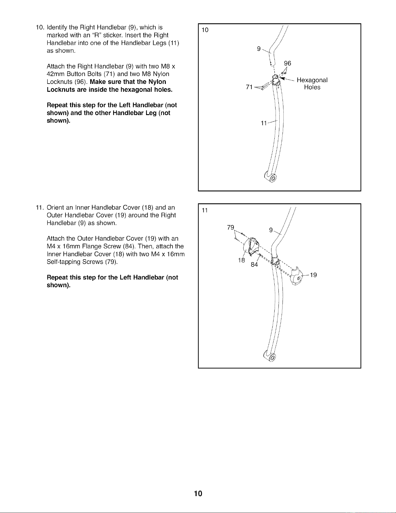
10. Identify the Right Handlebar (9), which is
marked with an "R" sticker. Insert the Right
Handlebar into one of the Handlebar Legs (11)
as shown.
Attach the Right Handlebar (9) with two M8 x
42mm Button Bolts (71) and two M8 Nylon
Locknuts (96). Make sure that the Nylon
Locknuts are inside the hexagonal holes.
Repeat this step for the Left Handlebar (not
shown) and the other Handlebar Leg (not
shown),
10
._;_ _ HexagonalHoles
71
11J
11. Orient an Inner Handlebar Cover (18) and an
Outer Handlebar Cover (19) around the Right
Handlebar (9) as shown.
Attach the Outer Handlebar Cover (19) with an
M4 x 16mm Flange Screw (84). Then, attach the
Inner Handlebar Cover (18) with two M4 x 16mm
Self-tapping Screws (79).
Repeat this step for the Left Handlebar (not
shown),
11
79
18
10
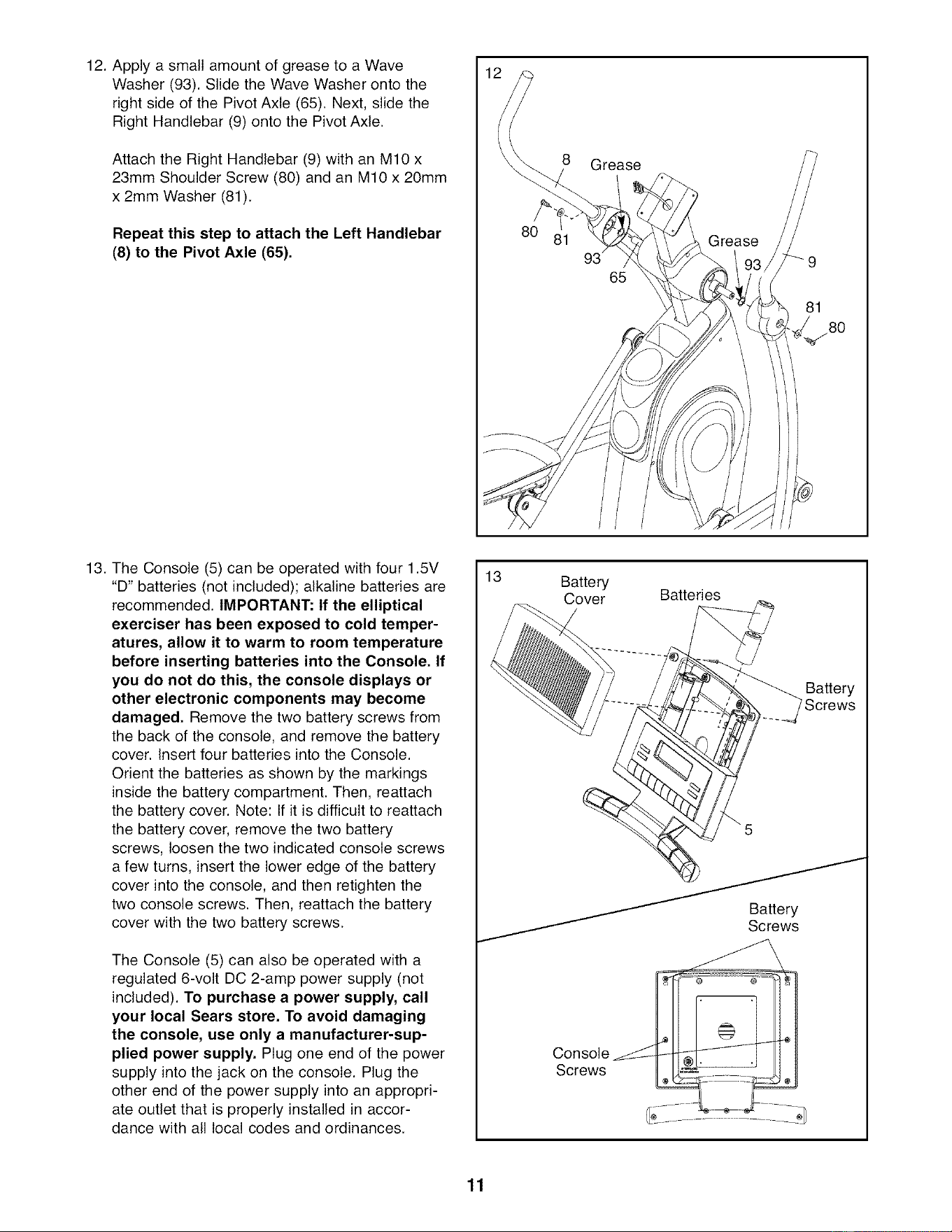
12. Apply a small amount of grease to a Wave
Washer (93). Slide the Wave Washer onto the
right side of the Pivot Axle (65). Next, slide the
Right Handlebar (9) onto the Pivot Axle.
Attach the Right Handlebar (9) with an M10 x
23mm Shoulder Screw (80) and an M10 x 20mm
x 2mm Washer (81).
Repeat this step to attach the Left Handlebar
(8) to the Pivot Axle (65),
8 Grease
Grease
81
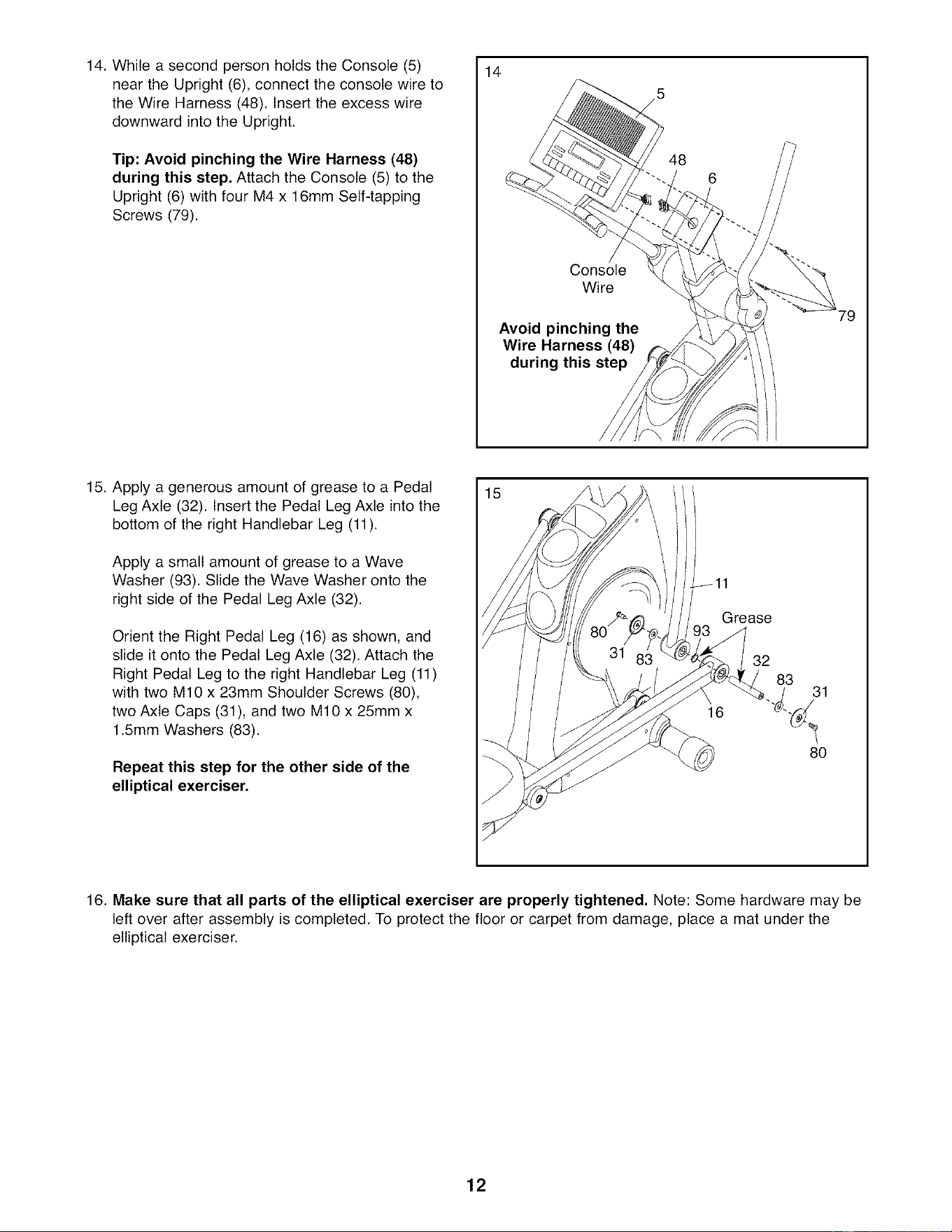
13. The Console (5) can be operated with four 1.5V
"D" batteries (not included); alkaline batteries are
recommended. IMPORTANT: If the elliptical
exerciser has been exposed to cold temper-
atures, allow it to warm to room temperature
before inserting batteries into the Console, If
you do not do this, the console displays or
other electronic components may become
damaged, Remove the two battery screws from
the back of the console, and remove the battery
cover. Insert four batteries into the Console.
Orient the batteries as shown by the markings
inside the battery compartment. Then, reattach
the battery cover. Note: If it is difficult to reattach
the battery cover, remove the two battery
screws, loosen the two indicated console screws
a few turns, insert the lower edge of the battery
cover into the console, and then retighten the
two console screws. Then, reattach the battery
cover with the two battery screws.
The Console (5) can also be operated with a
regulated 6-volt DC 2-amp power supply (not
included). To purchase a power supply, call
your local Sears store, To avoid damaging
the console, use only a manufacturer-sup-
plied power supply, Plug one end of the power
supply into the jack on the console. Plug the
other end of the power supply into an appropri-
ate outlet that is properly installed in accor-
dance with all local codes and ordinances.
13
Battery
Cover
Batteries
Battery
7Screws
Console
Screws
11
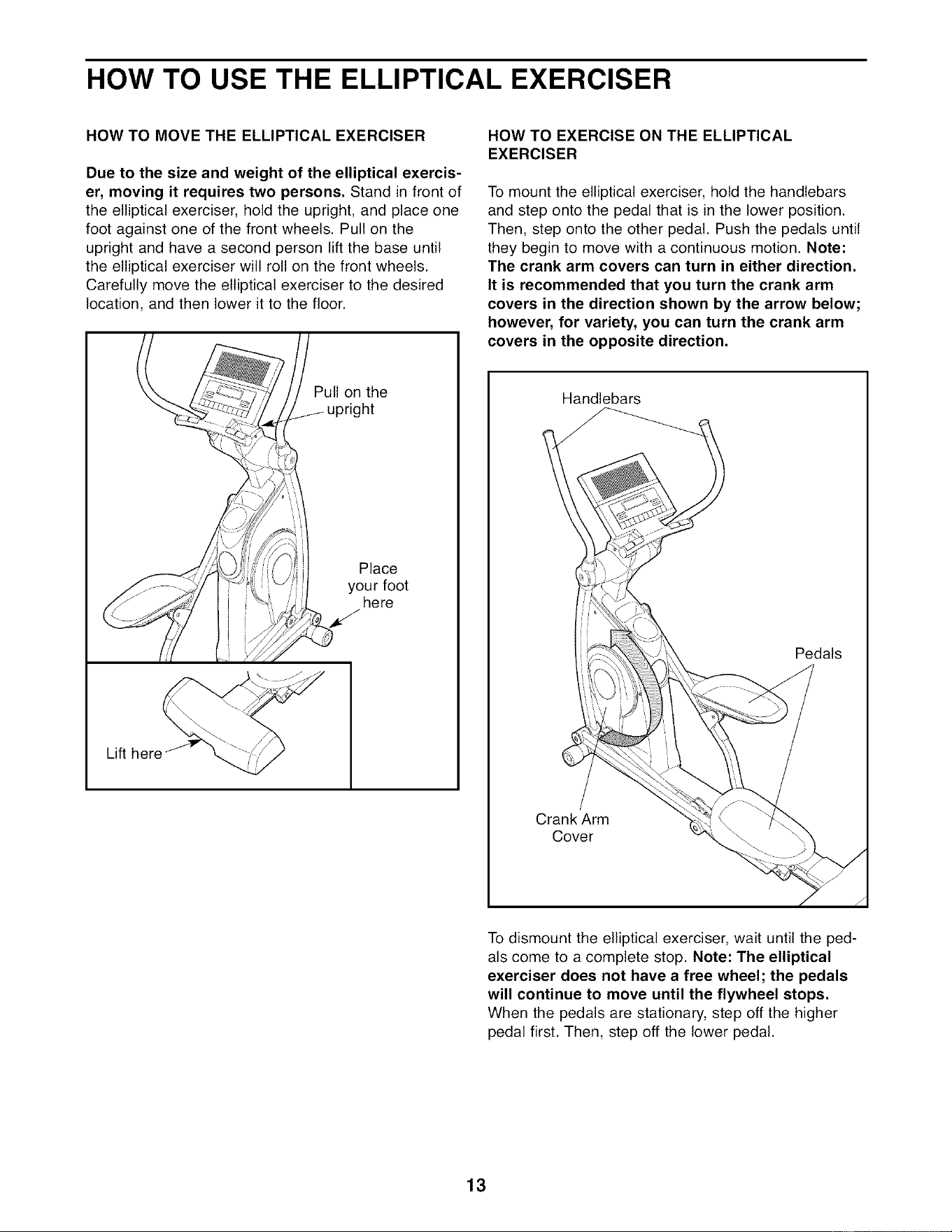
14. While a second person holds the Console (5)
near the Upright (6), connect the console wire to
the Wire Harness (48). Insert the excess wire
downward into the Upright.
Tip: Avoid pinching the Wire Harness (48)
during this step. Attach the Console (5) to the
Upright (6) with four M4 x 16mm Self-tapping
Screws (79).
14
Console
Wire
Avoid pinching the
Wire Harness (48)
during this step
79
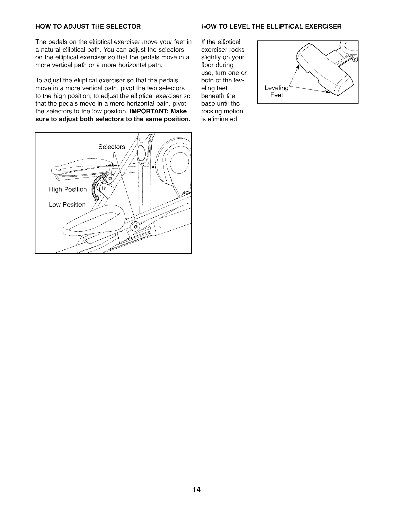
15. Apply a generous amount of grease to a Pedal
Leg Axle (32). Insert the Pedal Leg Axle into the
bottom of the right Handlebar Leg (11).
Apply a small amount of grease to a Wave
Washer (93). Slide the Wave Washer onto the
right side of the Pedal Leg Axle (32).
Orient the Right Pedal Leg (16) as shown, and
slide it onto the Pedal Leg Axle (32). Attach the
Right Pedal Leg to the right Handlebar Leg (11)
with two M10 x 23mm Shoulder Screws (80),
two Axle Caps (31), and two M10 x 25mm x
1.5mm Washers (83).
Repeat this step for the other side of the
elliptical exerciser.
15
Grease
32
16
83
_. 31
80
16. Make sure that all parts of the elliptical exerciser are properly tightened, Note: Some hardware may be
left over after assembly is completed. To protect the floor or carpet from damage, place a mat under the
elliptical exerciser.
12
HOW TO USE THE ELLIPTICAL EXERCISER
HOW TO MOVE THE ELLIPTICAL EXERCISER
Due to the size and weight of the elliptical exercis-
er, moving it requires two persons, Stand in front of
the elliptical exerciser, hold the upright, and place one
foot against one of the front wheels. Pull on the
upright and have a second person lift the base until
the elliptical exerciser will roll on the front wheels.
Carefully move the elliptical exerciser to the desired
location, and then lower it to the floor.
Pull on the
ht
Place
your foot
here
HOW TO EXERCISE ON THE ELLIPTICAL
EXERCISER
To mount the elliptical exerciser, hold the handlebars
and step onto the pedal that is in the lower position.
Then, step onto the other pedal. Push the pedals until
they begin to move with a continuous motion. Note:
The crank arm covers can turn in either direction.
It is recommended that you turn the crank arm
covers in the direction shown by the arrow below;
however, for variety, you can turn the crank arm
covers in the opposite direction.
Handlebars
Pedals
To dismount the elliptical exerciser, wait until the ped-
als come to a complete stop. Note: The elliptical
exerciser does not have a free wheel; the pedals
will continue to move until the flywheel stops.
When the pedals are stationary, step off the higher
pedal first. Then, step off the lower pedal.
13
HOW TO ADJUST THE SELECTOR HOW TO LEVEL THE ELLIPTICAL EXERCISER
The pedals on the elliptical exerciser move your feet in
a natural elliptical path. You can adjust the selectors
on the elliptical exerciser so that the pedals move in a
more vertical path or a more horizontal path.
To adjust the elliptical exerciser so that the pedals
move in a more vertical path, pivot the two selectors
to the high position; to adjust the elliptical exerciser so
that the pedals move in a more horizontal path, pivot
the selectors to the low position. IMPORTANT: Make
sure to adjust both selectors to the same position.
If the elliptical
exerciser rocks
slightly on your
floor during
use, turn one or
both of the lev-
eling feet
beneath the
base until the
rocking motion
is eliminated.
Leveling
Feet
Selectors
14
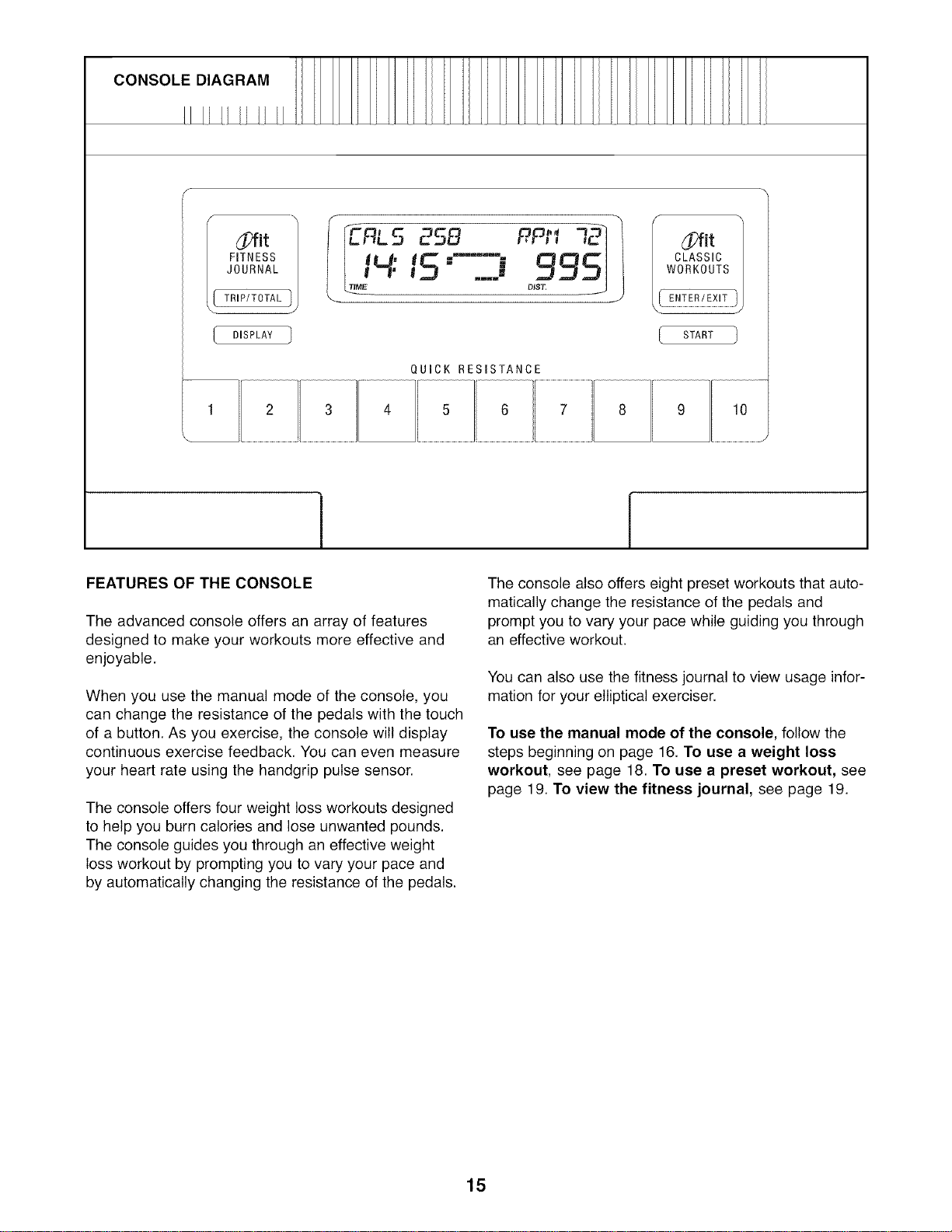
CONSOLE DIAGRAM
FITNESS
JOURNAL
TRP/TOTAL
DISPLAY
H"15 o,,, s:
QUICK RESISTANCE
_[Tfit
CLASSIC
WORKOUTS
J
I START
[
FEATURES OF THE CONSOLE
The advanced console offers an array of features
designed to make your workouts more effective and
enjoyable.
When you use the manual mode of the console, you
can change the resistance of the pedals with the touch
of a button. As you exercise, the console will display
continuous exercise feedback. You can even measure
your heart rate using the handgrip pulse sensor.
The console offers four weight loss workouts designed
to help you burn calories and lose unwanted pounds.
The console guides you through an effective weight
loss workout by prompting you to vary your pace and
by automatically changing the resistance of the pedals.
The console also offers eight preset workouts that auto-
matically change the resistance of the pedals and
prompt you to vary your pace while guiding you through
an effective workout.
You can also use the fitness journal to view usage infor-
mation for your elliptical exerciser.
To use the manual mode of the console, follow the
steps beginning on page 16. To use a weight loss
workout, see page 18. To use a preset workout, see
page 19. To view the fitness journal, see page 19.
15
HOW TO USE THE MANUAL MODE
Note: If there is a sheet of clear plastic on the face of
the console, remove the plastic.
1. Begin pedaling to turn on the console.
A moment after you turn on the console, the dis-
plays will light.
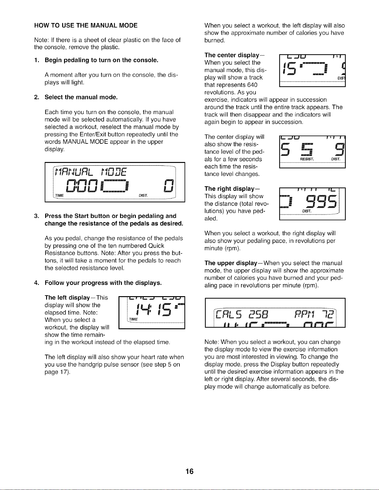
2. Select the manual mode.
Each time you turn on the console, the manual
mode will be selected automatically. If you have
selected a workout, reselect the manual mode by
pressing the Enter/Exit button repeatedly until the
words MANUAL MODE appear in the upper
display.
It1! _LJI-1L. I gUzJ_
¢3,Y3 ¢'1 =..... == t"3
LI'LI U = =
mEm=uR=mml m
DIST,
.
Press the Start button or begin pedaling and
change the resistance of the pedals as desired.
As you pedal, change the resistance of the pedals
by pressing one of the ten numbered Quick
Resistance buttons. Note: After you press the but-
tons, it will take a moment for the pedals to reach
the selected resistance level.
4. Follow your progress with the displays.
The left display--This
display will show the
elapsed time. Note:
When you select a
workout, the display will
show the time remain-
I
ing in the workout instead of the elapsed time.
The left display will also show your heart rate when
you use the handgrip pulse sensor (see step 5 on
page 17).
When you select a workout, the left display will also
show the approximate number of calories you have
burned.
The center display--
When you select the
manual mode, this dis-
play will show a track
that represents 640
revolutions. As you
L= .,JU I _ I|
15"---""
mmmm _
exercise, indicators will appear in succession
around the track until the entire track appears. The
track will then disappear and the indicators will
again begin to appear in succession.
The center display will
also show the resis-
tance level of the ped-
als for a few seconds
each time the resis-
tance level changes.
The right display--
This display will show
the distance (total revo-
lutions) you have ped-
aled.
-J 995
When you select a workout, the right display will
also show your pedaling pace, in revolutions per
minute (rpm).
The upper display--When you select the manual
mode, the upper display will show the approximate
number of calories you have burned and your ped-
aling pace in revolutions per minute (rpm).
[
IERL5 ESB PPrl I
dm t, t£ w --...... % t=_£=1£ =_
Note: When you select a workout, you can change
the display mode to view the exercise information
you are most interested in viewing. To change the
display mode, press the Display button repeatedly
until the desired exercise information appears in the
left or right display. After several seconds, the dis-
play mode will change automatically as before.
16
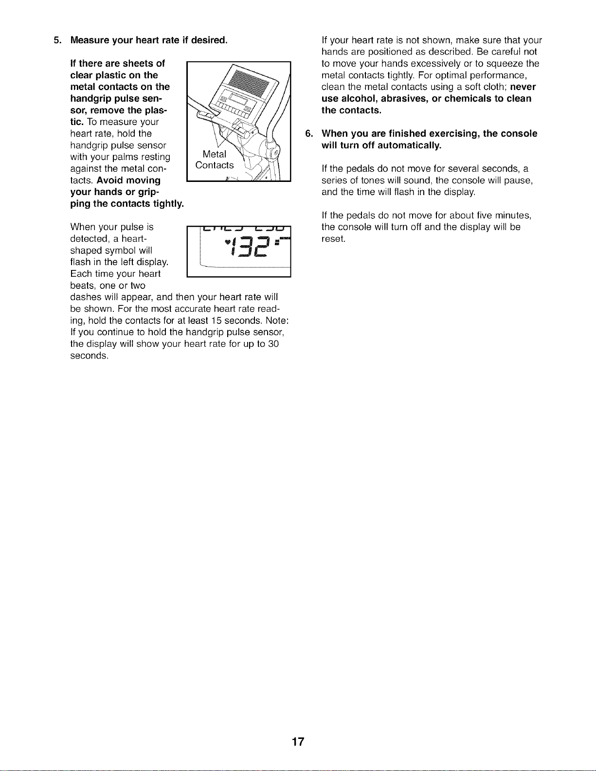
5. Measure your heart rate if desired.
If there are sheets of
clear plastic on the
metal contacts on the
handgrip pulse sen-
sor, remove the plas-
tic. To measure your
heart rate, hold the
handgrip pulse sensor
with your palms resting
against the metal con-
tacts. Avoid moving
your hands or grip-
ping the contacts tightly.
When your pulse is
detected, a heart-
shaped symbol will
flash in the left display.
Each time your heart
beats, one or two
132"
V =
dashes will appear, and then your heart rate will
be shown. For the most accurate heart rate read-
ing, hold the contacts for at least 15 seconds. Note:
If you continue to hold the handgrip pulse sensor,
the display will show your heart rate for up to 30
seconds.
.
If your heart rate is not shown, make sure that your
hands are positioned as described. Be careful not
to move your hands excessively or to squeeze the
metal contacts tightly. For optimal performance,
clean the metal contacts using a soft cloth; never
use alcohol, abrasives, or chemicals to clean
the contacts.
When you are finished exercising, the console
will turn off automatically.
If the pedals do not move for several seconds, a
series of tones will sound, the console will pause,
and the time will flash in the display.
If the pedals do not move for about five minutes,
the console will turn off and the display will be
reset.
17
HOW TO USE A WEIGHT LOSS WORKOUT
1. Begin pedaling to turn on the console.
See step 1 on page 16.
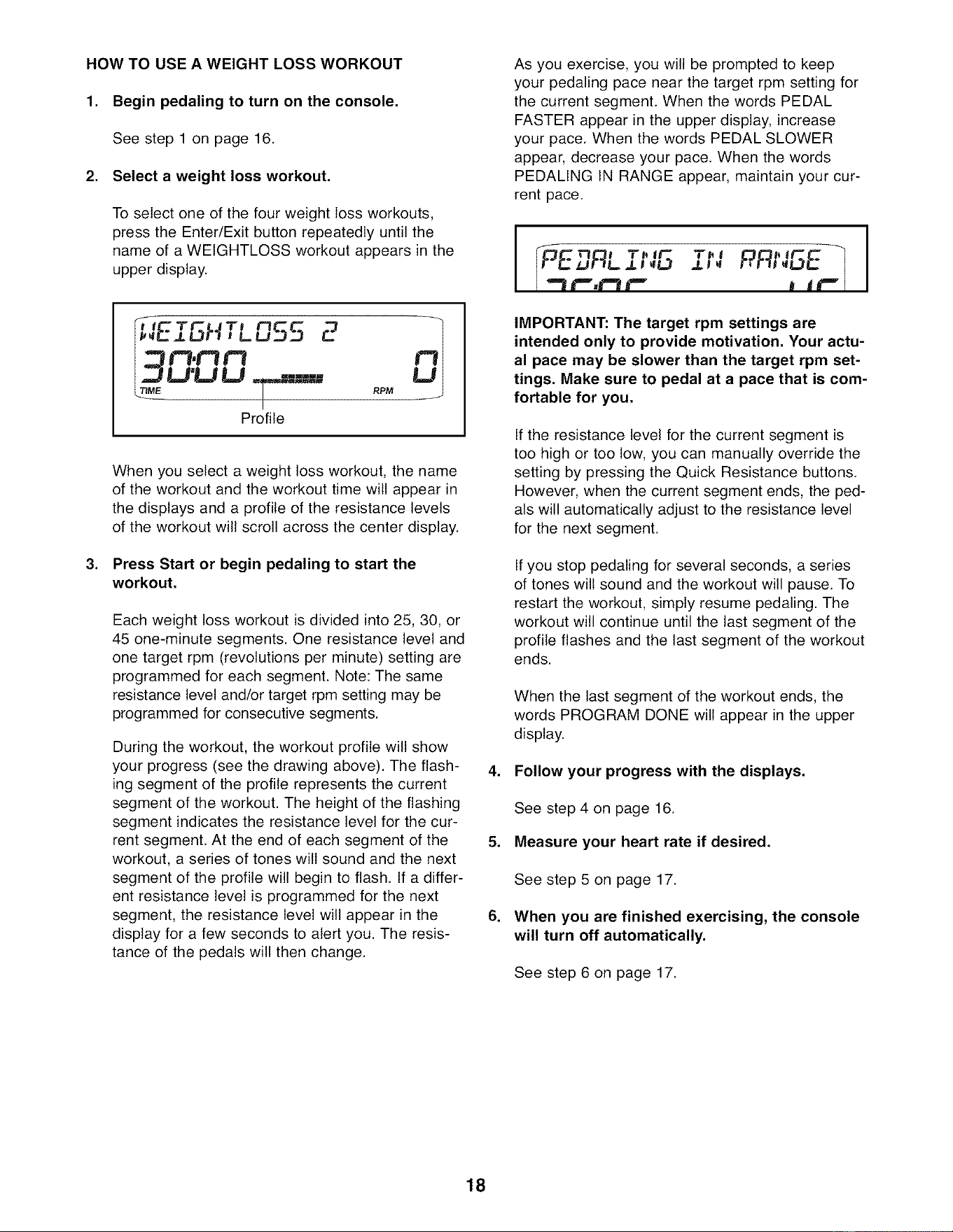
2. Select a weight loss workout,
To select one of the four weight loss workouts,
press the Enter/Exit button repeatedly until the
name of a WEIGHTLOSS workout appears in the
upper display.
,Lu :J 2
tl,t'3 r3
.,=TLI'U U =.====.,,=
TIME _ RPM
Profile
.
When you select a weight loss workout, the name
of the workout and the workout time will appear in
the displays and a profile of the resistance levels
of the workout will scroll across the center display.
Press Start or begin pedaling to start the
workout.
Each weight loss workout is divided into 25, 30, or
45 one-minute segments. One resistance level and
one target rpm (revolutions per minute) setting are
programmed for each segment. Note: The same
resistance level and/or target rpm setting may be
programmed for consecutive segments.
During the workout, the workout profile will show
your progress (see the drawing above). The flash-
ing segment of the profile represents the current
segment of the workout. The height of the flashing
segment indicates the resistance level for the cur-
rent segment. At the end of each segment of the
workout, a series of tones will sound and the next
segment of the profile will begin to flash. If a differ-
ent resistance level is programmed for the next
segment, the resistance level will appear in the
display for a few seconds to alert you. The resis-
tance of the pedals will then change.
As you exercise, you will be prompted to keep
your pedaling pace near the target rpm setting for
the current segment. When the words PEDAL
FASTER appear in the upper display, increase
your pace. When the words PEDAL SLOWER
appear, decrease your pace. When the words
PEDALING IN RANGE appear, maintain your cur-
rent pace.
IMPORTANT: The target rpm settings are
intended only to provide motivation. Your actu-
al pace may be slower than the target rpm set-
tings. Make sure to pedal at a pace that is com-
fortable for you.
If the resistance level for the current segment is
too high or too low, you can manually override the
setting by pressing the Quick Resistance buttons.
However, when the current segment ends, the ped-
als will automatically adjust to the resistance level
for the next segment.
If you stop pedaling for several seconds, a series
of tones will sound and the workout will pause. To
restart the workout, simply resume pedaling. The
workout will continue until the last segment of the
profile flashes and the last segment of the workout
ends.
When the last segment of the workout ends, the
words PROGRAM DONE will appear in the upper
display.
4. Follow your progress with the displays.
.
.
See step 4 on page 16.
Measure your heart rate if desired.
See step 5 on page 17.
When you are finished exercising, the console
will turn off automatically.
See step 6 on page 17.
18
HOW TO USE A PRESET WORKOUT
1. Begin pedaling to turn on the console.
See step 1 on page 16.
2. Select a preset workout,
To select one of the eight preset workouts, press
the Enter/Exit button repeatedly until the name of a
WORKOUT appears in the upper display.
I_=1¢3OL_ ¢3_ I T I
!"7,'?'1¢'1 =.--
Profile
.
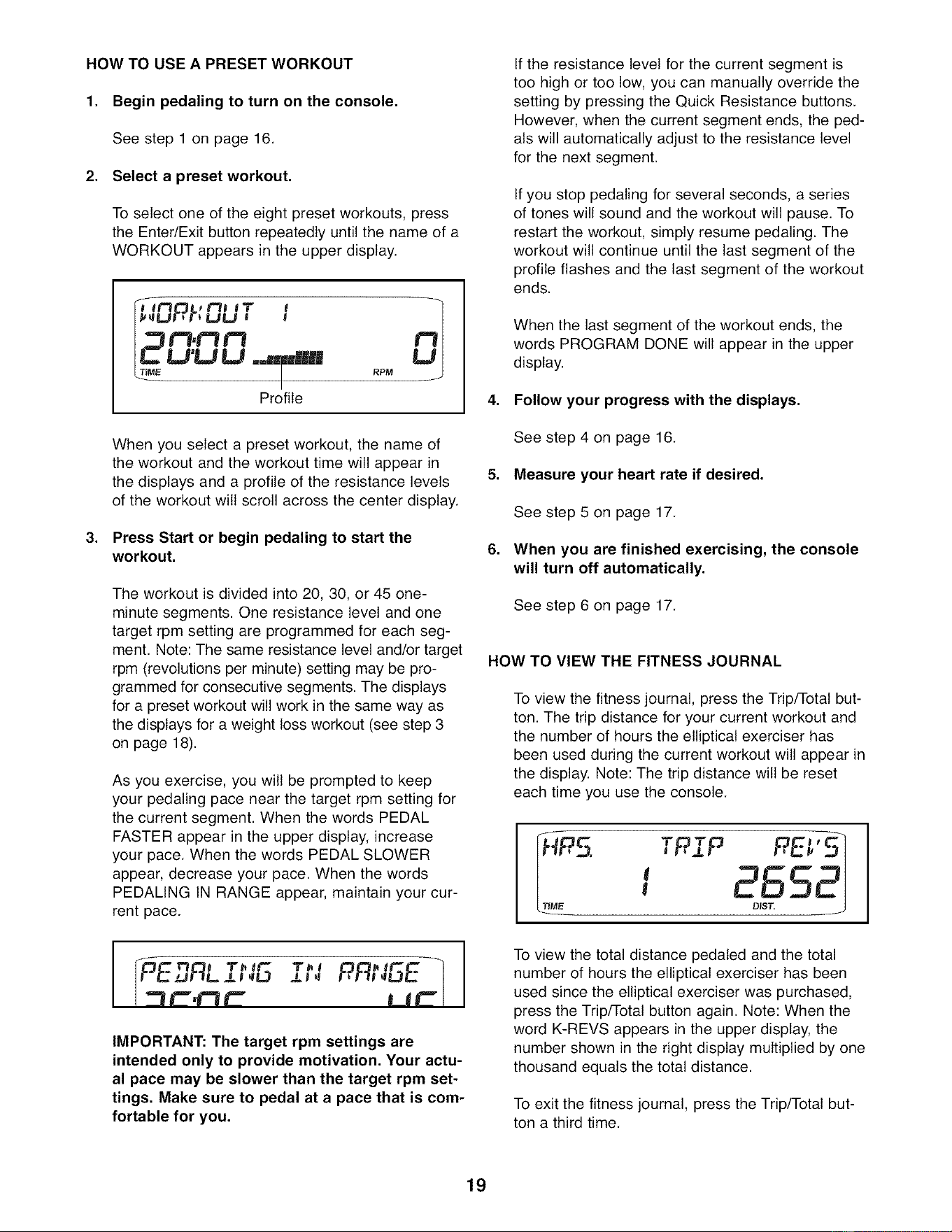
When you select a preset workout, the name of
the workout and the workout time will appear in
the displays and a profile of the resistance levels
of the workout will scroll across the center display.
Press Start or begin pedaling to start the
workout.
The workout is divided into 20, 30, or 45 one-
minute segments. One resistance level and one
target rpm setting are programmed for each seg-
ment. Note: The same resistance level and/or target
rpm (revolutions per minute) setting may be pro-
grammed for consecutive segments. The displays
for a preset workout will work in the same way as
the displays for a weight loss workout (see step 3
on page 18).
As you exercise, you will be prompted to keep
your pedaling pace near the target rpm setting for
the current segment. When the words PEDAL
FASTER appear in the upper display, increase
your pace. When the words PEDAL SLOWER
appear, decrease your pace. When the words
PEDALING IN RANGE appear, maintain your cur-
rent pace.
If the resistance level for the current segment is
too high or too low, you can manually override the
setting by pressing the Quick Resistance buttons.
However, when the current segment ends, the ped-
als will automatically adjust to the resistance level
for the next segment.
If you stop pedaling for several seconds, a series
of tones will sound and the workout will pause. To
restart the workout, simply resume pedaling. The
workout will continue until the last segment of the
profile flashes and the last segment of the workout
ends.
When the last segment of the workout ends, the
words PROGRAM DONE will appear in the upper
display.
4. Follow your progress with the displays.
See step 4 on page 16.
5. Measure your heart rate if desired.
.
See step 5 on page 17.
When you are finished exercising, the console
will turn off automatically.
See step 6 on page 17.
HOW TO VIEW THE FITNESS JOURNAL
To view the fitness journal, press the Trip/Total but-
ton. The trip distance for your current workout and
the number of hours the elliptical exerciser has
been used during the current workout will appear in
the display. Note: The trip distance will be reset
each time you use the console.
2ss
Pi P P,E '
I
i .=.lr. 4,=l r .
IMPORTANT: The target rpm settings are
intended only to provide motivation. Your actu-
al pace may be slower than the target rpm set-
tings. Make sure to pedal at a pace that is com-
fortable for you.
To view the total distance pedaled and the total
number of hours the elliptical exerciser has been
used since the elliptical exerciser was purchased,
press the Trip/Total button again. Note: When the
word K-REVS appears in the upper display, the
number shown in the right display multiplied by one
thousand equals the total distance.
To exit the fitness journal, press the Trip/Total but-
ton a third time.
19
MAINTENANCE AND TROUBLESHOOTING
Inspect and tighten all parts of the elliptical exerciser
regularly. Replace any worn parts immediately.
To clean the elliptical exerciser, use a damp cloth and
a small amount of mild soap. IMPORTANT: To avoid
damage to the console, keep liquids away from
the console and keep the console out of direct
sunlight,
BATTERY REPLACEMENT
If the console display becomes dim, the batteries
should be replaced; most console problems are the
result of low batteries. See assembly step 13 on page
11 for replacement instructions.
HOW TO LEVEL THE ELLIPTICAL EXERCISER
If the elliptical exerciser rocks slightly on your floor
during use, see HOW TO LEVEL THE ELLIPTICAL
EXERCISER on page 14.
HOW TO ADJUST THE REED SWITCH
If the console does not display correct feedback, the
reed switch should be adjusted. To adjust the reed
switch, first remove the screws from the left and right
side shields; there are two sizes of screws in the
side shields--note which size of screw you remove
from each hole, Gently pull the side shields apart and
remove the convenience tray.
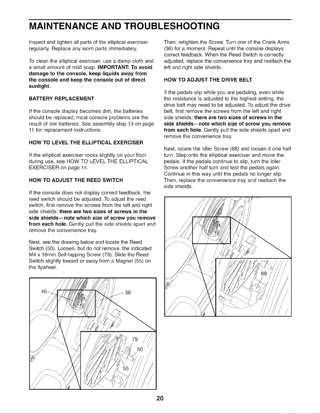
Next, see the drawing below and locate the Reed
Switch (50). Loosen, but do not remove, the indicated
M4 x 16mm Self-tapping Screw (79). Slide the Reed
Switch slightly toward or away from a Magnet (55) on
the flywheel.
Then, retighten the Screw. Turn one of the Crank Arms
(36) for a moment. Repeat until the console displays
correct feedback. When the Reed Switch is correctly
adjusted, replace the convenience tray and reattach the
left and right side shields.
HOW TO ADJUST THE DRIVE BELT
If the pedals slip while you are pedaling, even while
the resistance is adjusted to the highest setting, the
drive belt may need to be adjusted. To adjust the drive
belt, first remove the screws from the left and right
side shields; there are two sizes of screws in the
side shields--note which size of screw you remove
from each hole, Gently pull the side shields apart and
remove the convenience tray.
Next, locate the Idler Screw (68) and loosen it one half
turn. Step onto the elliptical exerciser and move the
pedals. If the pedals continue to slip, turn the Idler
Screw another half turn and test the pedals again.
Continue in this way until the pedals no longer slip.
Then, replace the convenience tray and reattach the
side shields.
20
EXERCISE GUIDELINES
These guidelines will help you to plan your exercise
program. For detailed exercise information, obtain a
reputable book or consult your physician. Remember,
proper nutrition and adequate rest are essential for
successful results.
EXERCISE INTENSITY
Whether your goal is to burn fat or to strengthen your
cardiovascular system, exercising at the proper inten-
sity is the key to achieving results. You can use your
heart rate as a guide to find the proper intensity level.
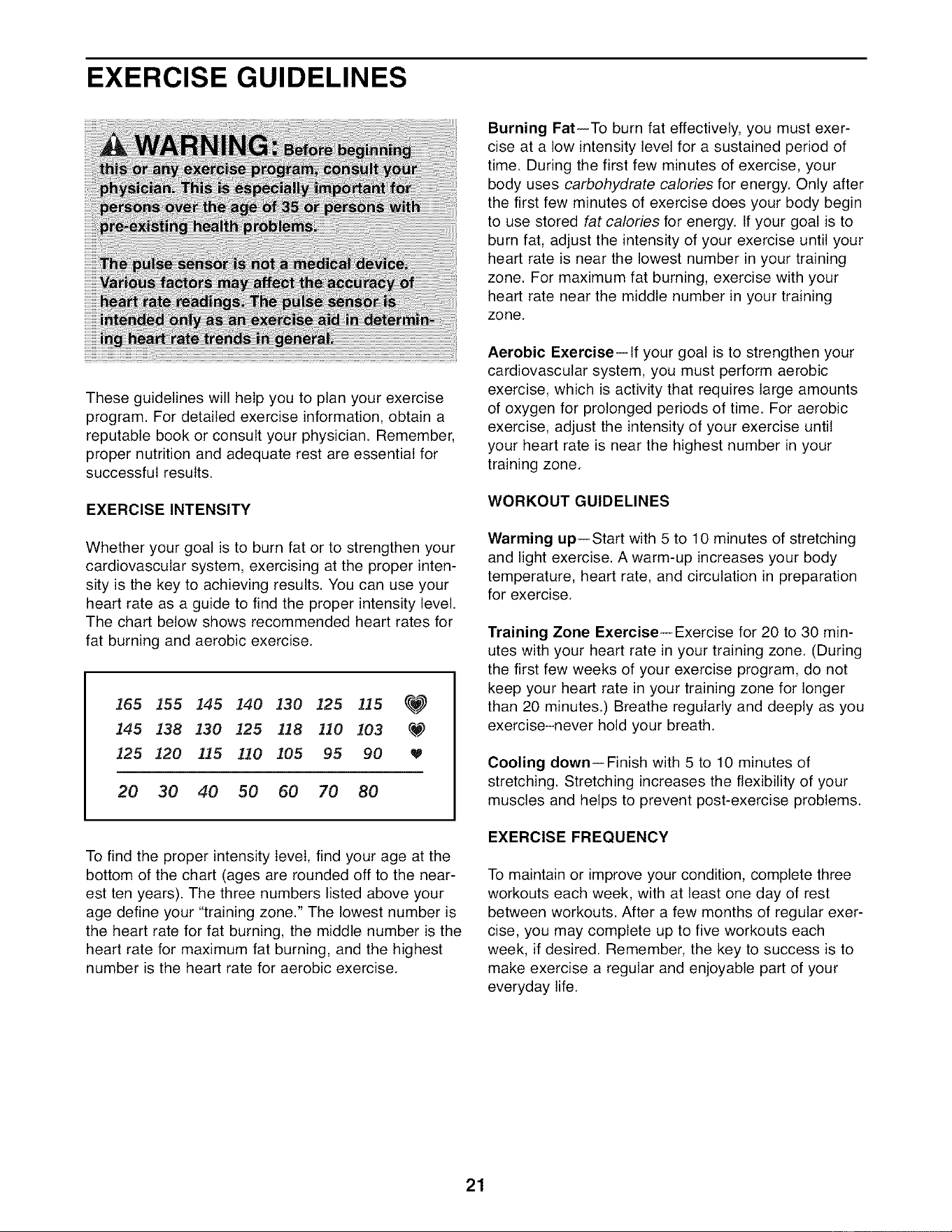
The chart below shows recommended heart rates for
fat burning and aerobic exercise.
165 155 145 140 130 125 115 _
145 138 130 125 118 110 103 _
125 120 115 110 105 95 90
20 30 40 50 60 70 80
To find the proper intensity level, find your age at the
bottom of the chart (ages are rounded off to the near-
est ten years). The three numbers listed above your
age define your "training zone." The lowest number is
the heart rate for fat burning, the middle number is the
heart rate for maximum fat burning, and the highest
number is the heart rate for aerobic exercise.
Burning Fat--To burn fat effectively, you must exer-
cise at a low intensity level for a sustained period of
time. During the first few minutes of exercise, your
body uses carbohydrate calories for energy. Only after
the first few minutes of exercise does your body begin
to use stored fat calories for energy, tf your goal is to
burn fat, adjust the intensity of your exercise until your
heart rate is near the lowest number in your training
zone. For maximum fat burning, exercise with your
heart rate near the middle number in your training
zone.
Aerobic Exercise--lf your goal is to strengthen your
cardiovascular system, you must perform aerobic
exercise, which is activity that requires large amounts
of oxygen for prolonged periods of time. For aerobic
exercise, adjust the intensity of your exercise until
your heart rate is near the highest number in your
training zone.
WORKOUT GUIDELINES
Warming up--Start with 5 to 10 minutes of stretching
and light exercise. A warm-up increases your body
temperature, heart rate, and circulation in preparation
for exercise.
Training Zone Exercise--Exercise for 20 to 30 min-
utes with your heart rate in your training zone. (During
the first few weeks of your exercise program, do not
keep your heart rate in your training zone for longer
than 20 minutes.) Breathe regularly and deeply as you
exercise-never hold your breath.
Cooling down--Finish with 5 to 10 minutes of
stretching. Stretching increases the flexibility of your
muscles and helps to prevent post-exercise problems.
EXERClSE FREQUENCY
To maintain or improve your condition, complete three
workouts each week, with at least one day of rest
between workouts. After a few months of regular exer-
cise, you may complete up to five workouts each
week, if desired. Remember, the key to success is to
make exercise a regular and enjoyable part of your
everyday life.
21
SUGGESTED STRETCHES
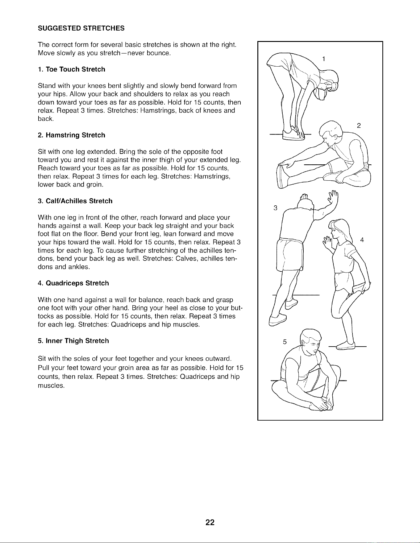
The correct form for several basic stretches is shown at the right.
Move slowly as you stretch--never bounce.
1. Toe Touch Stretch
Stand with your knees bent slightly and slowly bend forward from
your hips. Allow your back and shoulders to relax as you reach
down toward your toes as far as possible. Hold for 15 counts, then
relax. Repeat 3 times. Stretches: Hamstrings, back of knees and
back.
2. Hamstring Stretch
Sit with one leg extended. Bring the sole of the opposite foot
toward you and rest it against the inner thigh of your extended leg.
Reach toward your toes as far as possible. Hold for 15 counts,
then relax. Repeat 3 times for each leg. Stretches: Hamstrings,
lower back and groin.
3. Calf/Achilles Stretch
With one leg in front of the other, reach forward and place your
hands against a wall. Keep your back leg straight and your back
foot flat on the floor. Bend your front leg, lean forward and move
your hips toward the wall. Hold for 15 counts, then relax. Repeat 3
times for each leg. To cause further stretching of the achilles ten-
dons, bend your back leg as well. Stretches: Calves, achilles ten-
dons and ankles.
4. Quadriceps Stretch
With one hand against a wall for balance, reach back and grasp
one foot with your other hand. Bring your heel as close to your but-
tocks as possible. Hold for 15 counts, then relax. Repeat 3 times
for each leg. Stretches: Quadriceps and hip muscles.
5. Inner Thigh Stretch
Sit with the soles of your feet together and your knees outward.
Pull your feet toward your groin area as far as possible. Hold for 15
counts, then relax. Repeat 3 times. Stretches: Quadriceps and hip
muscles.
2
22
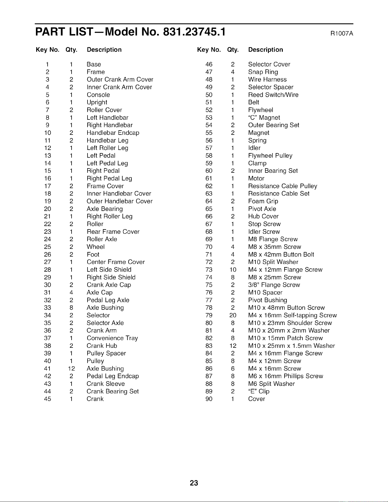
PART LIST--Model No. 831.23745.1 moo7A
Key No. Qty. Description Key No. Qty. Description
1 1 Base 46
2 1 Frame 47
3 2 Outer Crank Arm Cover 48
4 2 Inner Crank Arm Cover 49
5 1 Console 50
6 1 Upright 51
7 2 Roller Cover 52
8 1 Left Handlebar 53
9 1 Right Handlebar 54
10 2 Handlebar Endcap 55
11 2 Handlebar Leg 56
12 1 Left Roller Leg 57
13 1 Left Pedal 58
14 1 Left Pedal Leg 59
15 1 Right Pedal 60
16 1 Right Pedal Leg 61
17 2 Frame Cover 62
18 2 Inner Handlebar Cover 63
19 2 Outer Handlebar Cover 64
20 2 Axle Bearing 65
21 1 Right Roller Leg 66
22 2 Roller 67
23 1 Rear Frame Cover 68
24 2 Roller Axle 69
25 2 Wheel 70
26 2 Foot 71
27 1 Center Frame Cover 72
28 1 Left Side Shield 73
29 1 Right Side Shield 74
30 2 Crank Axle Cap 75
31 4 Axle Cap 76
32 2 Pedal Leg Axle 77
33 8 Axle Bushing 78
34 2 Selector 79
35 2 Selector Axle 80
36 2 Crank Arm 81
37 1 Convenience Tray 82
38 2 Crank Hub 83
39 1 Pulley Spacer 84
40 1 Pulley 85
41 12 Axle Bushing 86
42 2 Pedal Leg Endcap 87
43 1 Crank Sleeve 88
44 2 Crank Bearing Set 89
45 1 Crank 90
2 Selector Cover
4 Snap Ring
1 Wire Harness
2 Selector Spacer
1 Reed Switch/Wire
1 Belt
1 Flywheel
1 "C" Magnet
2 Outer Bearing Set
2 Magnet
1 Spring
1 Idler
1 Flywheel Pulley
1 Clamp
2 Inner Bearing Set
1 Motor
1 Resistance Cable Pulley
1 Resistance Cable Set
2 Foam Grip
1 Pivot Axle
2 Hub Cover
1 Stop Screw
1 Idler Screw
1 M8 Flange Screw
4 M8 x 35mm Screw
4 M8 x 42mm Button Bolt
2 M10 Split Washer
10 M4 x 12mm Flange Screw
8 M8 x 25mm Screw
2 3/8" Flange Screw
2 M10 Spacer
2 Pivot Bushing
2 M10 x 48mm Button Screw
20 M4 x 16mm Self-tapping Screw
8 M10 x 23mm Shoulder Screw
4 M10 x 20mm x 2mm Washer
8 M10 x 15mm Patch Screw
12 M10 x 25mm x 1.5mm Washer
2 M4 x 16mm Flange Screw
8 M4 x 12mm Screw
6 M4 x 16mm Screw
8 M6 x 16mm Phillips Screw
8 M6 Split Washer
2 "E" Clip
1 Cover
23

Key No. Qty. Description Key No. Qty. Description
91 4 M4 x 65mm Screw 97 2 M10 x 62mm Button Bolt
92 1 M4 x 12mm Screw 98 2 Selector Axle Cap
93 8 Wave Washer * - Hex Key
94 2 M10 X 35mm Shoulder Screw * - Grease Packet
95 3 M8 x 16mm Button Screw * - User's Manual
96 6 M8 Nylon Locknut
Specifications are subject to change without notice. See the back cover of this manual for information about
ordering replacement parts. *These parts are not illustrated. If a part is missing, call 1-888-533-1333.
24
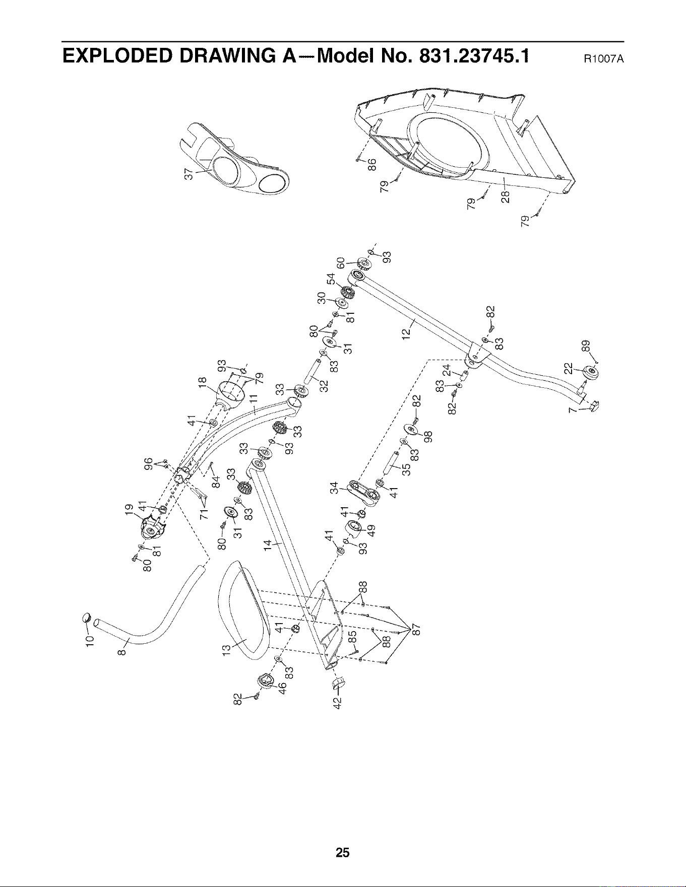
82 31
41
18
93
8O
31
30
54
60
93
37
86
79
\
Ill
X
r-
0
I'll
I
o
o
"_4
3>
0'_
66
74
23
79
91
75
38
27
52
36
I'll
X
I'--
0
13
I"11
63
I
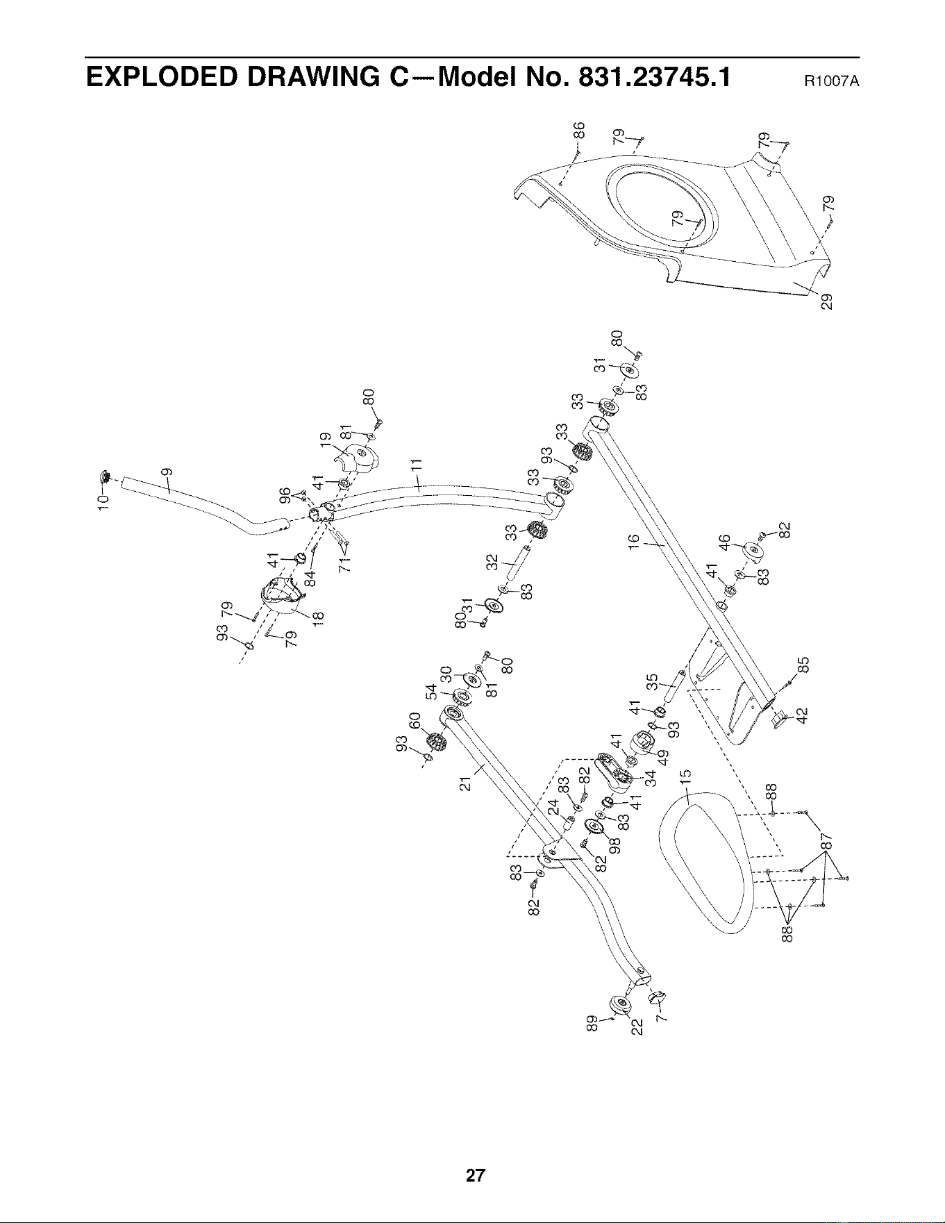
I%,)
89
2_
93
21
60
54
41
42
93 79
79
18
16
35
10-_
i
96
33
33
31
j3./ 80
29 <1
79
rT1
X
I--
0
I1"1
Q
0
I
e_.
.-.,.
tJ'l
33
o
o

Your Home
For repair--in your home--of all major brand appliances, lawn and garden equipment,
or heating and cooling systems, no matter who made it, no matter who sold it!
For the replacement parts, accessories, and user's manuals that you need to do-it-yourself.
For Sears professional installation of home appliances
and items like garage door openers and water heaters.
1-800-4-MY-HOME ® (1-800-469-4663)
Call anytime, day or night (U.S.A. and Canada)
www.seats.com www.seats.ca
Our Home
For repair of carry-in items like vacuums, lawn equipment,
and electronics, call or go on-line for the location of your nearest
Sears Parts & Repair Center.
1-800-488-1222 Call anytime, day or night (U.S.A. only)
www.sears.com
To purchase a protection agreement (U.S.A.)
or maintenance agreement (Canada) on a product serviced by Sears:
1-800-827-6655 (U.S.A.) 1-800-361-6665 (Canada)
Para pedir servicio de reparaci6n a domicilio, y para ordenar piezas:
1-888-SU-HOGAR _(1-888-784-6427)
.... Se f'
® Registered Trademark / TMTrademark / SMService Mark of Sears Brands, LLC
® Mama Registrada / TMMarca de Fabrica / SMMarca de Servicio de Sears Brands, LLC
f
ONE YEAR FULL WARRANTY
f
If this Sears Elliptical Exerciser fails due to a defect in material or workmanship within one year of the
date of purchase, call 1-800-4-MY-HOME ®(1-800-469-4663) to arrange for free repair (or replacement
if repair proves impossible). The resistance mechanism is warranted for 7 years. There is a lifetime
warranty on the frame.
This warranty does not apply when the Elliptical Exerciser is used commercially or for rental purposes.
This warranty gives you specific legal rights, and you may also have other rights which vary from state
to state.
Sears, Roebuck and Co., Hoffman Estates, IL 60179
J
J
Part No. 259680 R1007A Printed in China © 2007 ICON IP, Inc.