Loading ...
Loading ...
Loading ...
16
E
Checking Laser Accuracy
The laser tools are sealed and calibrated at the factory.
It is recommended that you perform an accuracy check
prior to using the laser for the rst time (in case the
laser was exposed to extreme temperatures) and then
regularly to ensure the accuracy of your work. When
performing any of the accuracy checks listed in this
manual, follow these guidelines:
• Use the largest area/distance possible, closest to the
operating distance. The greater the area/distance,
the easier to measure the accuracy of the laser.
• Place the laser on a smooth, at, stable surface that
is level in both directions.
• Mark the center of the laser beam.
Field Calibration Check
Checking Accuracy – Horizontal Beam,
Scan Direction (Fig. D)
Checking the horizontal scan calibration of the laser
requires two walls at least 30' (9 m) apart. It is important
to conduct a calibration check using a distance no
shorter than the distance of the applications for which
the tool will be used.
1. Attach the laser to a wall using its pivot bracket.
Make sure the laser is facing straight ahead.
2. Turn on the laser's horizontal beam and pivot the
laser approximately 45˚ so that the right-most end
of the laser line is striking the opposing wall at a
distance of at least 30' (9 m). Mark the center of
the beam (a).
3. Pivot the laser approximately 90˚ to bring the
left-most end of the laser line around to the mark
made in Step 2. Mark the center of the beam (b).
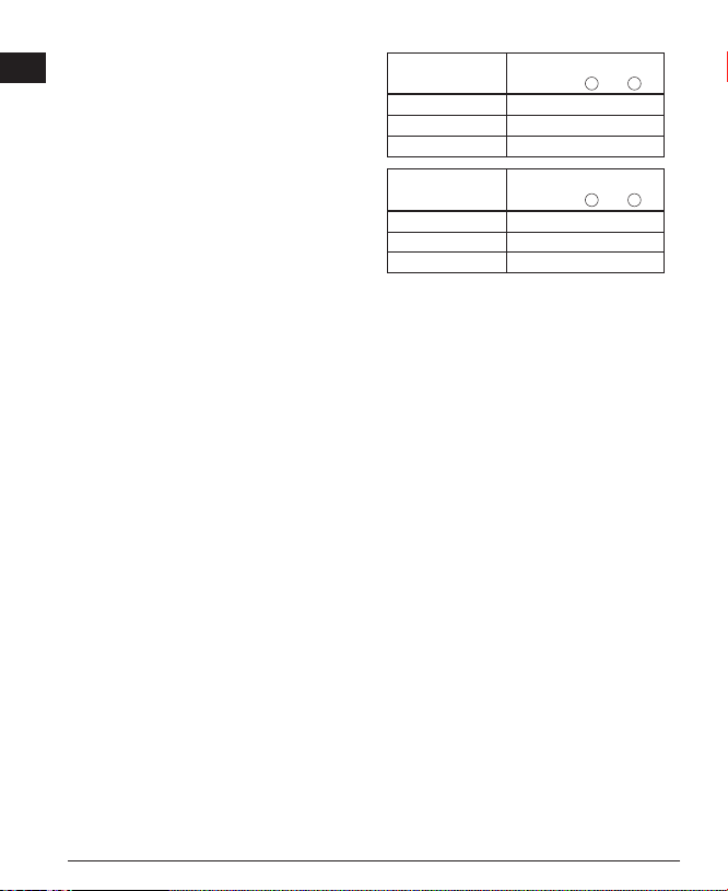
4. Measure the vertical distance between the marks.
• If the measurement is greater than the values
shown below, the laser must be serviced at an
authorized service center.
Distance
Between Walls
Allowable Distance
Between
a
and
b
30' 1/8"
40' 5/32"
50' 7/32"
Distance
Between Walls
Allowable Distance
Between
a
and
b
9.0 m 3.1 mm
12.0 m 4.2 mm
15.0 m 5.2 mm
Checking Accuracy – Horizontal Beam,
Pitch Direction (Fig. E)
Checking the horizontal pitch calibration of the laser
requires a single wall at least 30' (9 m) long. It is
important to conduct a calibration check using a
distance no shorter than the distance of the applications
for which the tool will be used.
1. Attach the laser to one end of a wall using its
pivot bracket.
2. Turn on the laser's horizontal beam and pivot
the laser toward the opposite end of the wall and
approximately parallel to the adjacent wall.
3. Mark the center of the beam at two locations (a, b)
at least 30' (9m) apart.
4. Reposition the laser to the opposite end of
the wall.
5. Turn on the laser's horizontal beam and pivot the
laser back toward the rst end of the wall and
approximately parallel to the adjacent wall.
6. Adjust the height of the laser so that the center of
the beam is aligned with the nearest mark (b).
7. Mark the center of the beam (c) directly above or
below the farthest mark (a).
8. Measure the distance between these two
marks (a, c).
Loading ...
Loading ...
Loading ...