Loading ...
Loading ...
Loading ...
13 English
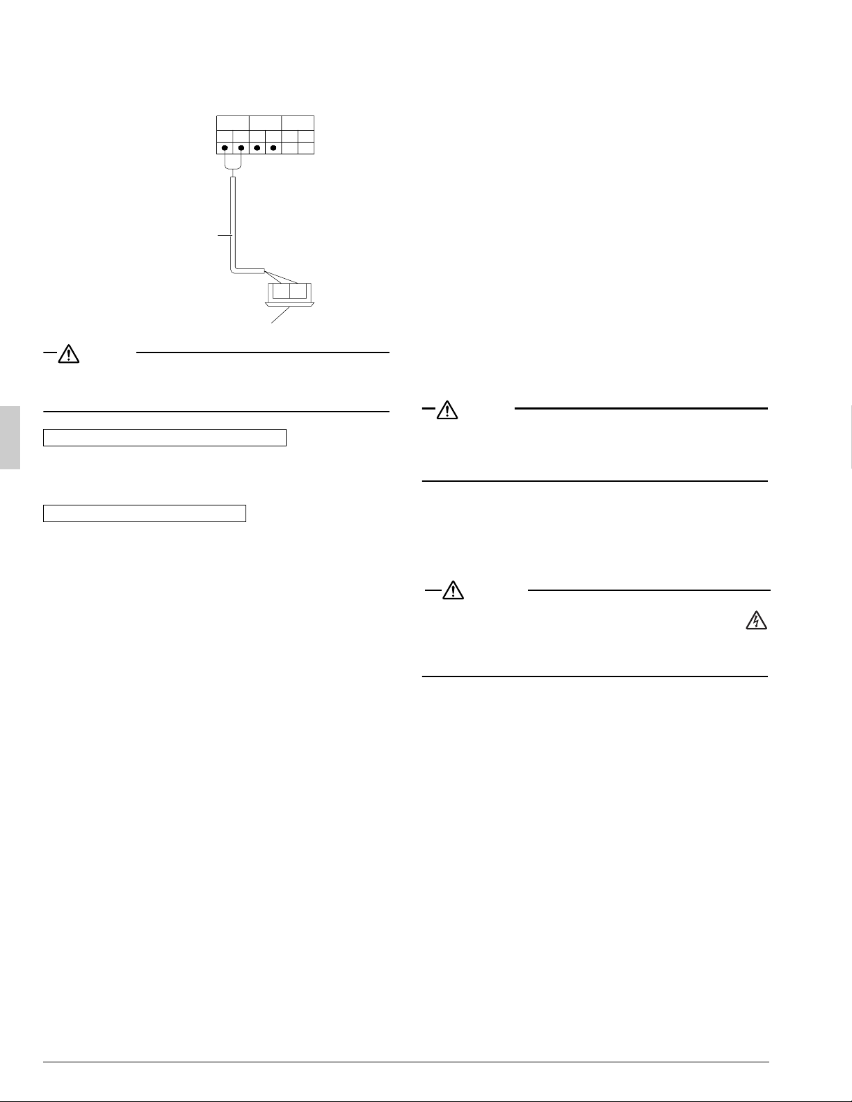
7-4 Transmission wiring connection procedure
• If an excessive force is applied while connecting a cable to the
terminal block on the PC board, the PC board may be damaged.
CAUTION
• For low-noise operation, it is necessary to install the optional “Exter-
nal control adaptor for outdoor unit”.
For details, see the installation manual attached to the adaptor.
Make sure to observe the restrictions below. If they are not
observed, transmission error may occur.
Maximum wiring length: 3280 ft.
• Never connect 208/230V to the terminal block for the transmission
wiring.
Doing so will break the entire system.
• The transmission wiring from the indoor unit must be connected to
the F1/F2 (TO IN/D UNIT) terminals on the PC board in the outdoor
unit.
∗ Make sure to use sheathed two-core cables of AWG18-16 in the wir-
ing shown above.
∗ All cables used in the wiring between the units should be pro-
cured on the site.
8. CHECKS AFTER COMPLETION OF
WORK
After completing the work, make sure to confirm the following
items:
1. Connection of drain piping and removal of transportation metal:
Refer to “5. CAUTIONS ON INSTALLATION”.
2. Connection of power supply wiring and tightening of screws:
Refer to “7-3 Power supply wiring connection procedure”.
3. Connection of transmission wiring and tightening of screws:
Refer to “7-4 Transmission wiring connection procedure”.
4. Freezing connection of refrigerant piping
Refer to “6. REFRIGERANT PIPING WORK”.
5. Piping size and heat insulation:
Refer to “6-1 Selection of piping material”, “6-5 Heat insulation
of piping”.
6. Check of stop valve:
Confirm that the stop valve is open on both the liquid line and gas
line.
7. Record of amount of additional refrigerant:
Record the amount on the label stuck on the back of the front panel.
8. Measurement of insulation in main power circuit:
• Use the megatester for 500 V.
• Do not use any megatester for low voltage electric circuits except
230 V.
(Wiring between the outdoor unit and the indoor unit)
CAUTION
<To piping technician>
• Make sure to open the stop valve after finishing the piping work.
(Operating the air conditioner with the stop valve shut may damage
the compressor.)
9. TEST RUN PROCEDURE
A crankcase heater is mounted for smooth startup. Make sure to
turn on the power 6 hours before starting operation for supplying
the power to the crankcase heater.
WARNING
• Make sure to close the front panel before leaving the outdoor
unit in the power ON status.
• To avoid injury, always make sure that the circuit breaker on
the power supply panel of the installation is switched off before doing
any work.
Cautions before turning on the power
• Put the insulating cover securely onto the control box.
• After turning on the power, check the settings and LED indica-
tors on the PC board (A2P) in the outdoor unit through the
opening of the insulating cover.
Caution on the wiring length between units
Cautions on the wiring between units
F
1
F
2
F
1
F
2
F1 F2
Terminal block (X2M)
Use the conductor
of sheathed wire
(2 wire) (no polarity)
Indoor unit
01_EN_3PN07193-7L.fm Page 13 Thursday, February 16, 2012 8:22 PM
Loading ...
Loading ...
Loading ...