Loading ...
Loading ...
Loading ...
One Piece oor Instal
Otis
ADJUSTMENTS: If, after installation of opener, door does
not open or close satisfactorily, follow adjustment steps 16
and 17 on Pages 12 and 13,,
[_<
!
I
m
LJ
P
INSTALL LIGHT AND LENS: Refer to Step T8, Page 13,
IdIGH POINT
or- TRAVEL
REMOTE INSTALLATION PROCEDURES
CE I LING SUPPORT
HEADER BRACKET
t DIAMETER THIN WALLEO EMT
'\o o o o o o__...2jo o o o
_cuT AsREQ'D--J
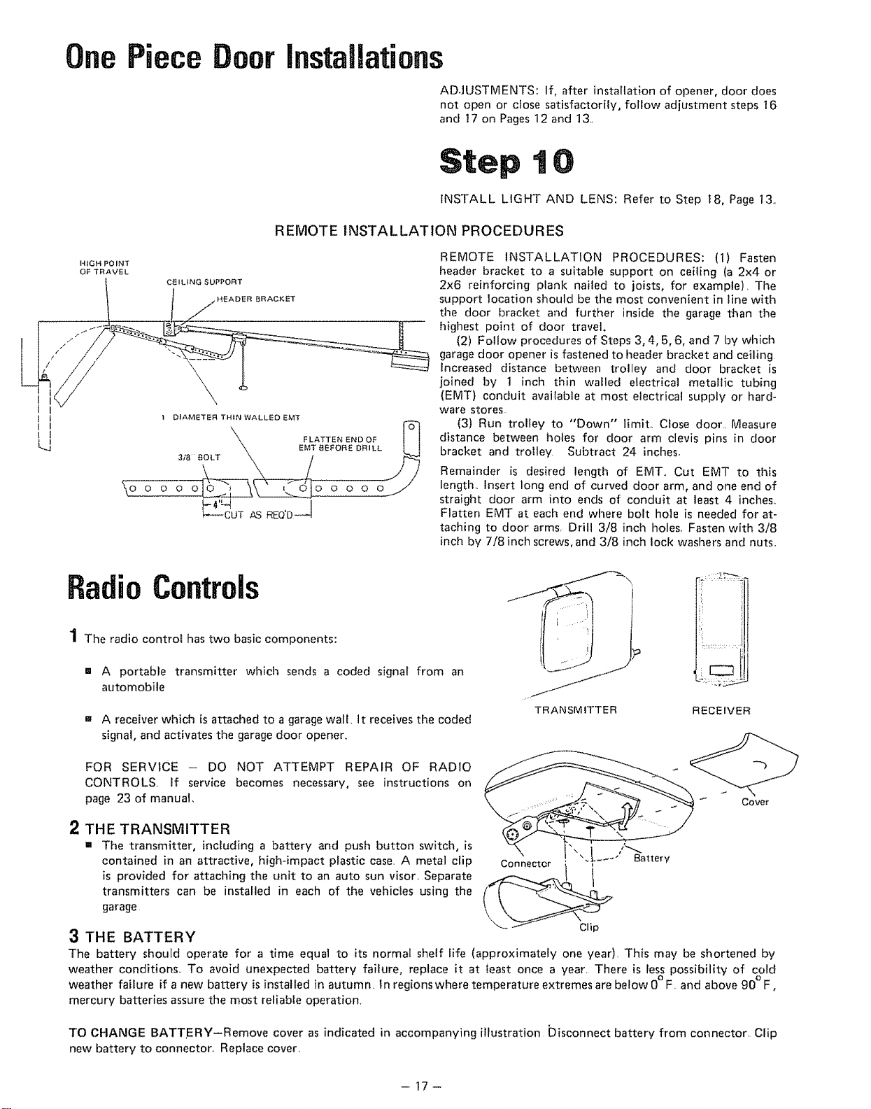
REMOTE INSTALLATION PROCEDURES: (1) Fasten
header bracket to a suitable support on ceiling (a 2x4 or
2x6 reinforcing plank nailed to joists, for example), Tile
support location should be the most convenient in line with
the door bracket and further inside the garage than tile
highest point of door travel.
(2) Follow procedures of Steps 3,4,5,6, and 7 by which
garage door opener is fastened to header bracket and ceiling
Increased distance between trolley and door bracket is
joined by 1 inch thin walled electrical metallic tubing
(EMT) conduit available at most electrical supply or hard-
ware stores,
(3) Run trolley to "Down" limit,, Close door, Measure
distance between holes for door arm clevis pins in door
bracket and trolley Subtract 24 inches,,
Remainder is desired length of EMT,, Cut EMT to this
length. Insert long end of curved door arm, and one end of
straight door arm into ends of conduit at least 4 inches,,
Flatten EMT at each end where bolt hole is needed for at-
taching to door arms, Drill 3/8 inch holes, Fasten with 3/8
inch by 7/8 inch screws, and 3/8 inch lock washers and nuts,,
Radio Controls
1 The radio control has two basic components:
=' A portable transmitter which sends a coded signal from an
automobile
= A receiver which is attached to a garage wall. It receives the coded
signal, and activates the garage door opener..
TRANSMITTER RECEIVER
FOR SERVICE - DO NOT ATTEMPT REPAIR OF RADIO
CONTROLS, If service becomes necessary, see instructions on
page 23 of manual,
CovBr
2 THE TRANSMITTER
= The transmitter, including a battery and push button switch, is "_ I ,'_
contained in an attractive, high4mpact plastic case, A metal clip ".L ..... Battery
is provided for attaching the unit to an auto sun visor, Separate
transmitters can be installed in each of the vehicles using the
garage
3 THE BATTERY Clip
The battery should operate for a time equal to its normal shelf fife (approximately one year), This may be shortened by
weather conditions° To avoid unexpected battery failure, replace it at least once a year. There is Iess possibility of cold
o O
weather failure if a new battery is installed in autumn, In regionswhere temperature extremes are below 0 F, and above 90 F,
mercury batteries assure the most reliable operation.
TO CHANGE BATTERY-Remove cover as indicated in accompanying illustration Disconnect battery from connector. CEip
new battery to connector. Replace cover,
-17-
Loading ...
Loading ...
Loading ...