Loading ...
Loading ...
Loading ...
instaJlation
t4K]UNTING
FLANGE
COD_o
LABEL
SIGNAL
CODE LABEL
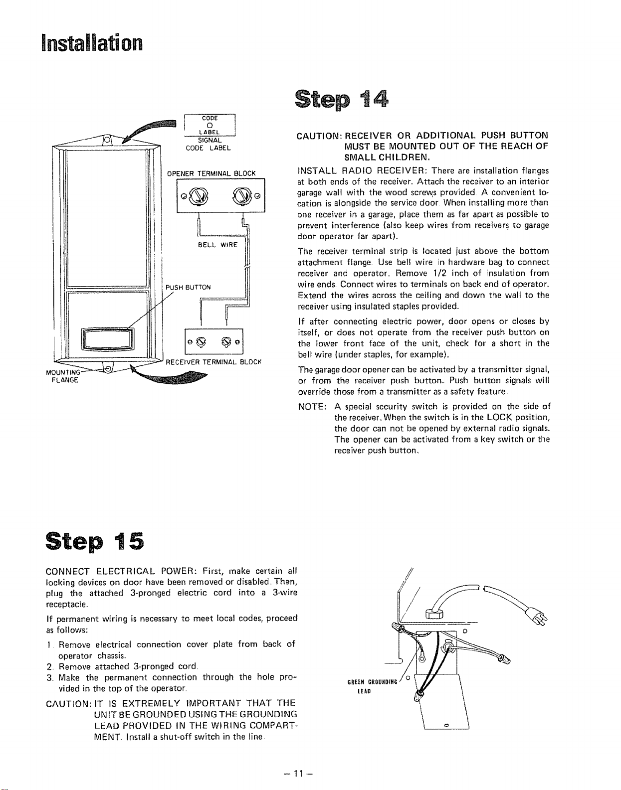
OPENER TERMINAL BLOCK
ooi
BELL WIRE
SH BUTTON
ir
, k.... t
RECEIVER TERMINAL BLOCK
CAUTION: RECEIVER OR ADDITIONAL PUSH BUTTON
MUST BE MOUNTED OUT OF THE REACH OF
SMALL CHILDREN.
INSTALL RADIO RECEIVER: There are installation flanges
at both ends of the receiver, Attach the receiver to an interior
garage wall with the wood screw, s provided. A convenient lo-
cation is alongside the service door When installing more than
one receiver in a garage, place them as far apart as possible to
prevent interference (also keep wires from receivers to garage
door operator far apart)°
The receiver terminal strip is located just above the bottom
attachment flange Use bell wire in hardware bag to connect
receiver and operator.. Remove 1/2 inch of insulation from
wire ends.. Connect wires to terminals on back end of operaton.
Extend the wires across the ceiling and down the wall to the
receiver using insulated staples provided°
tf after connecting electric power, door opens or closes by
itself, or does not operate from the receiver push button on
the lower front face of the unit, check for a short in the
belt wire (under staples, for example).,
The garage door opener can be activated by a transmitter signal,
or from the receiver push button° Push button signals will
override those from a transmitter as a safety feature,
NOTE: A special security switch is provided on the side of
the receiver,. When the switch is in the LOCK position,
the door can not be opened by external radio signals°
The opener can be activated from a key switch or the
receiver push button,
CONNECT ELECTRICAL POWER: First, make certain all
locking devices on door have been removed or disabled. Then,
plug the attached 3-pronged electric cord into a 3-wire
receptacle,
If permanent wiring is necessary to meet local codes, proceed
as follows:
I, Remove electrical connection cover plate from back of
operator chassis°
2, Remove attached 3-pronged cord,
3,, Make the permanent connection through the hole pro-
vided in the top of the operator.
CAUTION; IT IS EXTREMELY IMPORTANT THAT THE
UN IT BE GROUNDED USING THE GROUNDING
LEAD PROVIDED IN THE WIRING COMPART-
MENT.. Install a shut-off switch in the line.
GR£EN
LEAD
o
-tl-
Loading ...
Loading ...
Loading ...