User’s Guide

2
CONTENTS
Safety Instructions .................................................................................................................................. 3
Quick Setup Guide .................................................................................................................................. 7
Back Panel ............................................................................................................................................... 8
Overview - IRX115s ................................................................................................................................ 10
IRX115s - Block Diagram....................................................................................................................... 11
IRX115s Specifications .......................................................................................................................... 12
Applications / Features .......................................................................................................................... 13
Loudspeaker Placement and Suspension ................................................................................................ 14
Cables & Connectors ............................................................................................................................. 15
Application Examples ............................................................................................................................. 16
Trouble Shooting ................................................................................................................................... 19
Warranty Information ............................................................................................................................. 20
Contact Information .............................................................................................................................. 21

3
The IRX115s covered by this manual is not intended for use in high moisture environments. Moisture can damage the
speaker cone and surround and cause corrosion of electrical contacts and metal parts. Avoid exposing the speakers to
direct moisture.
Keep speakers out of extended or intense direct sunlight. The driver suspension will prematurely dry out and finished
surfaces may be degraded by long-term exposure to intense ultra-violet (UV) light. The IRX115s can generate
considerable energy. When placed on a slippery surface such as polished wood or linoleum, the speaker may move due
to its acoustical energy output. Precautions should be taken to assure that the speaker does not fall off a stage or table
on which it is placed.
HEARING DAMAGE, PROLONGED EXPOSURE TO EXCESSIVE SPL
The IRX115s is capable of generating sound pressure levels (SPL) sufficient to cause permanent hearing damage to performers, production
crew, and audience members. Caution should be taken to avoid prolonged exposure to SPL in excess of 85 dB.
CARE & CLEANING
IRX115s may be cleaned with a dry cloth. Do not allow moisture into any of the openings in the system. Ensure that the system is unplugged
from the AC outlet before cleaning.
THIS APPARATUS CONTAINS POTENTIALLY LETHAL VOLTAGES. TO PREVENT ELECTRIC SHOCK OR HAZARD, DO NOT REMOVE CHASSIS,
MIXER MODULE, OR AC INPUT COVERS. NO USER SERVICEABLE PARTS INSIDE. REFER SERVICING TO QUALIFIED SERVICE PERSONNEL.
WEEE Notice
The Directive 2012/19/EU on Waste Electrical and Electronic Equipment (WEEE), which entered into force as European law
on 14/02/2014, resulted in a major change in the treatment of electrical equipment at end-of-life. The purpose of this Directive
is, as a first priority, the prevention of WEEE, and in addition, to promote the reuse, recycling and other forms of recovery of such
wastes so as to reduce disposal. The WEEE logo on the product or on its box indicating collection for electrical and electronic
equipment consists of the crossed-out wheeled bin, as shown below. 15.
This product must not be disposed of or dumped with your other household waste. You are liable of dispose of all your electronic or electrical
waste equipment by relocating over to the specified collection point for recycling of such hazardous waste. Isolated collection and proper
recovery of your electronic and electrical waste equipment at the time of disposal will allow us to help conserving natural resources.
Moreover, proper recycling of the electronic and electrical waste equipment will ensure safety of human health and environment. For more
information about electronica and electrical waste equipment disposal, recovery, and collection points, please contact your local city center,
household waste disposal service, shop from where you purchased the equipment, or manufacturer of the equipment.
RoHS Compliance
This product is in compliance with Directive 2011/65/EU and (EU) 2015/863 of the European Parliament and of the Council of 19.
31/03/2015 on the restriction of the use of certain hazardous substances in electrical and electronic equipment.
REACH
REACH (Regulation No 1907/2006) addresses the production and use of chemical substances and their potential impacts on human health
and the environment. Article 33 (1) of REACH Regulation requires suppliers to inform the recipients if an article contains more than 0.1%
(per weight per article) of any substance(s) on the Substances of Very High Concern (SVHC) Candidate List (‘REACH candidate list’).
This product contains the substance ‘’lead’’ (CAS-No. 7439-92-1) in a concentration of more than 0.1% per weight.
At the time of release of this product, except for the lead substance, no other substances of REACH candidate list are contained in a
concentration of more than 0.1% per weight in this product.
Note: on June 27, 2018, lead was added to the REACH candidate list. The indusion of lead in the REACH candidate list does not mean that
lead-containing materials pose an immediate risk or results in a restriction of permissibility of its use.
SAFETY INSTRUCTIONS

4
1. READ these instructions.
2. KEEP these instructions.
3. HEED all warnings.
4. FOLLOW all instructions.
5. DO NOT use this apparatus near water.
6. CLEAN ONLY with dry cloth.
7. DO NOT block any ventilation openings. Install in accordance with the manufacturer’s instructions.
8. DO NOT install near any heat sources such as radiators, heat registers, stoves, or other apparatus (including amplifiers) that
produce heat.
9. DO NOT defeat the safety purpose of the polarized or grounding type plug. A polarized plug has two blades with one wider
than the other. A grounding type plug has two blades and a third grounding prong. The wider blade or the third prong are
outlet.
10. PROTECT the power cord from being walked on or pinched, particularly at plugs, convenience receptacles, and the point
where they exit from the apparatus.
11. ONLY USE attachments/accessories specified by the manufacturer.
12.
USE ONLY with a cart, stand, tripod, bracket, or table specified by the manufacturer, or sold with the apparatus.
When a cart is used, use caution when moving the cart/apparatus combination to avoid injury from tip-over.
13. UNPLUG this apparatus during lightning storms or when unused for long periods of time.
14. REFER all servicing to qualified service personnel. Servicing is required when the apparatus has been damaged in any
way, such as power-supply cord or plug is damaged, liquid has been spilled or objects have fallen into the apparatus, the
apparatus has been exposed to rain or moisture, does not operate normally, or has been dropped.
15. DO NOT expose this apparatus to dripping or splashing and ensure that no objects filled with liquids, such as vases, are
placed on the appratus.
16. To completely disconnect this apparatus from the AC Mains, disconnect the power supply cord plug from the AC receptacle.
17. Where the mains plug or an appliance coupler is used as the disconnect device, the disconnect device shall remain readily
operable.
18. DO NOT overload wall outlets or extension cords beyond their rated capacity as this can cause electric shock or fire.
19. For adequate ventilation, do not install this equipment in a confined or enclosed space, such as a book case or similar unit.
20. Product ventilation should not be impeded by covering the ventilation openings with items such as newspaper, tablecloths,
curtains, etc.
The exclamation point, within an equilateral triangle, is intended to alert the user to the presence of important operating
and maintenance (servicing) instructions in the literature accompanying the product.
The exclamation point, within an equilateral triangle, is intended to alert the user to the presence of important operating
and maintenance (servicing) instructions in the literature accompanying the product.
WARNING: To reduce the risk of fire or electrical shock, do not expose this apparatus to rain or moisture.
WARNING: No naked flame sources – such as lighted candles –should be placed on the product.
WARNING: Equipment shall be connected to a MAINS socket outlet with a protective earthing connection.
SAFETY INSTRUCTIONS

5
WARNING: This product is intended to be operated ONLY from the voltages listed on the back panel. Operation from other voltages other
than those indicated may cause irreversible damage to the product and void the products warranty. The use of AC Plug Adapters is cautioned
because it can allow the product to be plugged into voltages in which the product was not designed to operate. If you are unsure of the
correct operational voltage, please contact your local distributor and/or retailer. If the product is equipped with a detachable power cord, use
only the type provided, or specified, by the manufacturer or your local distributor.
OPERATING TEMPERATURE RANGE: -20°C- 40°C (-4°F -104°F)
WARNING TO REDUCE THE RISK OF ELECTRIC SHOCK,
DO NOT EXPOSE THIS EQUIPMENT TO RAIN OR MOISTURE.
RISQUE DE CHOC ELECTRIQUE NE PAS OUVRIR
WARNING: Do Not Open! Risk of Electrical Shock. Voltages in this equipment are hazardous to life. No user-serviceable parts inside. Refer
all servicing to qualified service personnel.
Place the equipment near a main power supply outlet and make sure that you can easily access the power breaker switch.
WARNING: Batteries (battery pack or batteries installed) shall not be exposed to excessive heat such as sunshine, fire or the like.
CAUTION: Danger of explosion if battery is incorrectly replaced. Replace only with the same or equivalent type. Please dispose of any used
batteries properly, following any local regulations. Do not incinerate.
WARNING: DO NOT EXPOSE BATTERIES OR BATTERY PACK TO EXCESSIVE HEAT, SUCH AS THAT FROM OPEN FLAMES, DIRECT
SUNSHINE, ETC.
CAUTION: DANGER OF EXPLOSION IF BATTERY IS INCORRECTLY REPLACED, REPLACE ONLY WITH THE SAME OR EQUIVALENT TYPE.
DO NOT UNDER ANY CIRCUMSTANCES OPERATE THE UNIT WITH THE WRONG VOLTAGE SELECTED. DOING SO MAY RESULT IN SERIOUS
DAMAGE TO YOUR PA SYSTEM WHICH WILL NOT BE COVERED BY WARRANTY.
FCC AND CANADA EMC COMPLIANCE INFORMATION: This device complies with Part 15 of the FCC Rules. Operation is subject to
the following two conditions
1. This device may not cause harmful interference, and (2) this device must accept any interference received, including interference that
may cause undesired operation.
CAUTION: Changes or modifications not expressly approved by the manufacturer could void the user’s authority to operate this device.
NOTE: This equipment has been tested and found to comply with the limits for a Class B digital device, pursuant to Part 15 of the FCC
Rules. These limits are designed to provide reasonable protection against harmful interference in a residential installation. This equipment
generates uses and can radiate radio frequency energy and, if not installed and used in accordance with the instructions, may cause
harmful interference to radio communications. However, there is no guarantee that interference will not occur in a particular installation.
If this equipment does cause harmful interference to radio or television reception, which can be determined by turning the equipment off
and on, the user is encouraged to try to correct the interference by one or more of the following measures: Reorient or relocate the receiving
antenna. Increase the separation between the equipment and receiver. Connect the equipment into an outlet on a circuit different from that
to which the receiver is connected. Consult the dealer or an experienced radio/TV technician for help.
CAUTION: This product is for non-residential use only.
CAN ICES-3 (B)/NMB-3(B)
Protective earthing terminal. The apparatus should be connected to a mains socket outlet with a protective earthing
connection.
SAFETY INSTRUCTIONS

6
SAFETY INSTRUCTIONS
WIRELESS TRANSMITTER COMPLIANCE INFORMATION: The term “IC:” before the radio certification number only signifies that
Industry Canada technical specifications were met.
Le terme «IC:» avant le numero de certification radio signifie seulement que les specifications techniques d’lndustrie Canada ont ete
respectees.
This device contains licence-exempt transmitter(s)/receiver(s) that comply with Innovation, Science and Economic Development
Canada’s licence-exempt RSS(s). Operation is subject to the following two conditions (1) this device may not cause harmful
interference, and (2) this device must accept any interference, including interference that may cause undesired operation of the device.
Cet appareil contient des émetteurs / récepteurs exemptés de licence conformes aux RSS (RSS) d’Innovation, Sciences et
Développement économique Canada. L’exploitation est autorisee aux deux conditions suivantes : (1) l’appareil ne doit pas produire
de brouillage, et (2) l’utilisateur de l’appareil doit accepter tout brouillage radioelectrique subi, meme si le brouillage est susceptible
d’en compromettre le fonctionnement.
This equipment complies with FCC and IC radiation exposure limits set forth for an uncontrolled environment. This equipment should
be installed and operated with minimum distance 20cm between the radiator and your body. This transmitter must not be co-located or
operating in conjunction with any other antenna or transmitter.
Cet appareil est conforme a FCC et IC !’exposition aux rayonnements limites fixees pour un environnement non controle. Cet appareil
doit etre installe et utilize avec une distance minimale de 20cm entre le radiateur et votre corps. Cet transmetteur ne doit pas etre cositue
ou operant en liaison avec toute autre antenne ou transmetteur.
EU COMPLIANCE INFORMATION:
Hereby, HARMAN Professional, Inc., declares that the equipment type IRX115s is in compliance to the following:
European Union Restriction of Hazardous Substances Recast (RoHS2) Directive 2011/65/EU; European Union WEEE (recast)
Directive 2012/19/EU; European Union Registration, Evaluation, Authorization and Restriction of Chemicals (REACH) Directive
1907/2006.
You may obtain a free copy of the full Declaration of Conformity by visiting:
http://www.jblpro.com/www/product-support/downloads
Prevention of hearing loss
Caution: Permanent hearing loss may occure if earphones or headphones are used at high volume for prolonged periods of time.
Note: To prevent possible hearing damage, do not listen at high volume levels for long periods.
ENVIRONMENTAL:
此标识适用于在中华人民共和国销售的电子信息产品 . 标识中间的数字为环保实用期限的年数 .
7
QUICK SETUP GUIDE
Congratulations on your purchase of JBL Professional IRX115s loudspeakers! We know you are anxious to get up and running as
fast as possible, which is why you are reading this section. The following will help you get set up as soon as possible.
Packaging Contents
Your IRX115s system should include the following:
1 x IRX115s speaker
1 x 10'(3m) IEC Power Cable
1 x Quick Start Guide
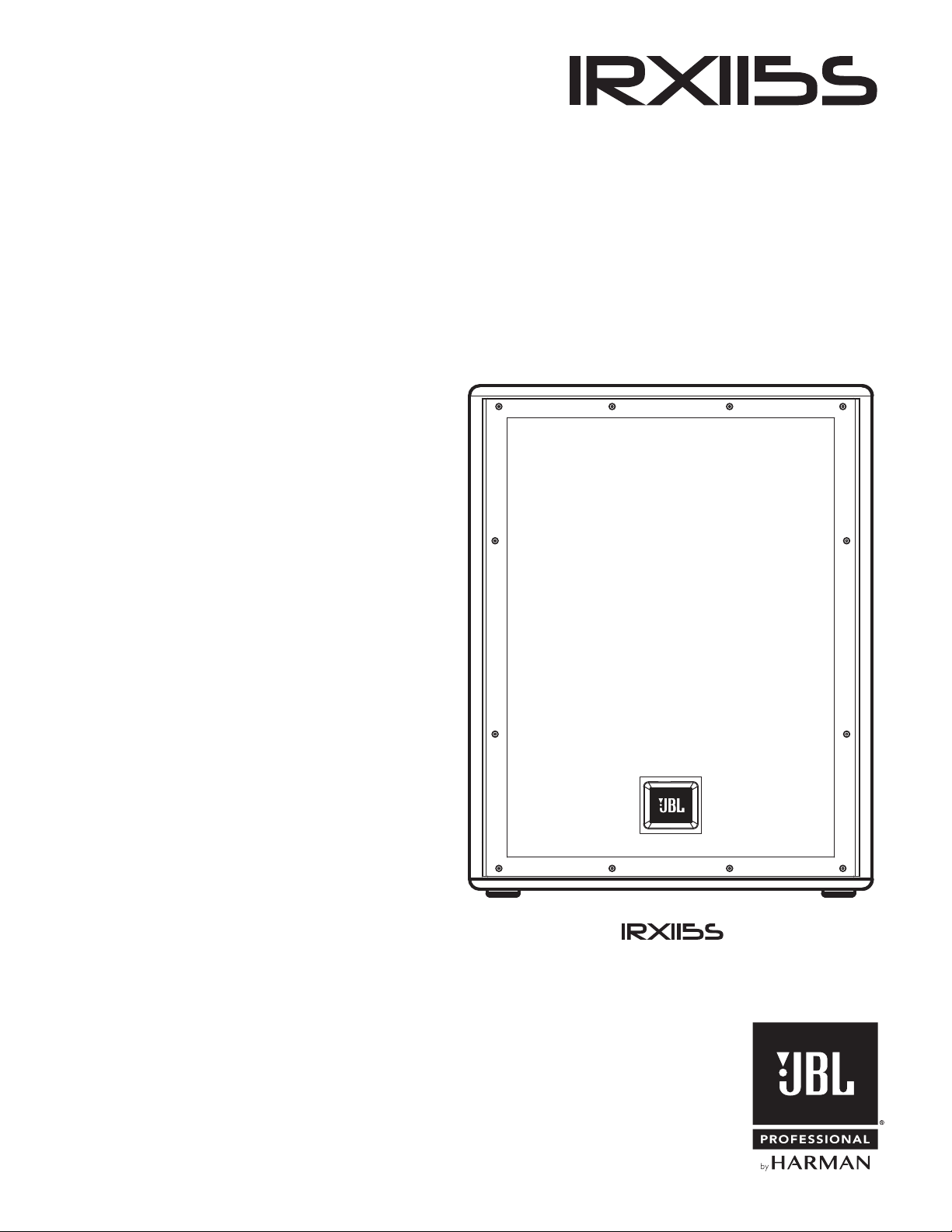
Unbox it
Open the top of the box. Turn box upside down, then lift box up to reveal speaker.Lay box on its side.
Configuration Options
Floor Standing Subwoofer Mounted
1
1 2
2
3
8
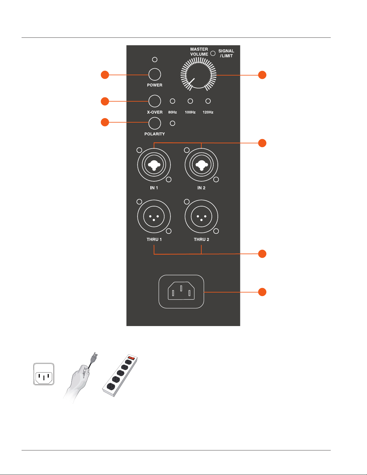
POWER ON THE UNIT
1. Connect the power cord to the Power Receptacle (G).
2. Press the Power Button [A] to engage power.
PLUG IN THE INPUTS
1. Turn the Master Volume (D) all the way to the left before
connecting any inputs.
2. Connect your devices to the Input Jacks (E).
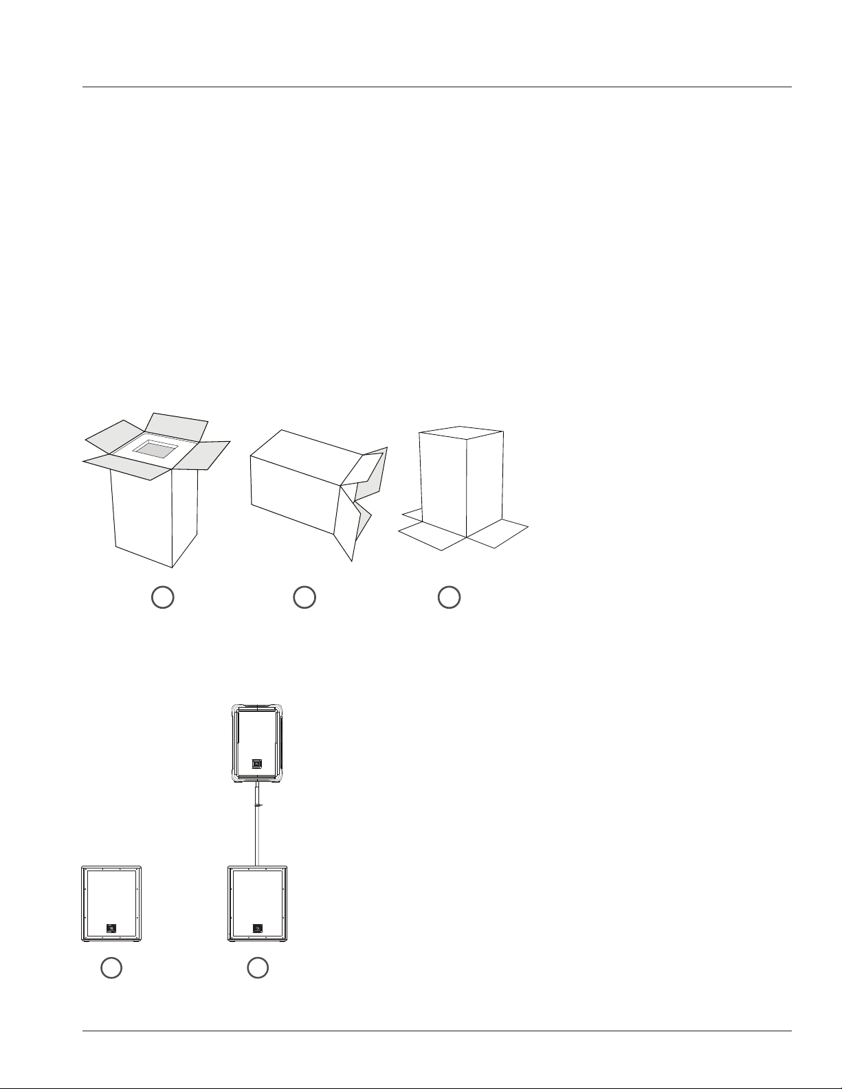
BACK PANEL
F
E
XLR Male Loop Thru
XLR-1/4”
Combo Inputs
G
D
Power Receptacle
Master Volume
A
B
C
Power Button
Crossover Frequency
Polarity Button

9
BACK PANEL
A. Power Button
Press the Power Button to engage power.
B. Crossover Frequency
Select the frequency you wish by pressing the Crossover Frequency
Button (B). Choose crossover frequency EQ from one type to another type
(cycling) by repeatedly pressing the Crossover Frequency Button (B).
C. Polarity Button
Toggle polarity between ON and OFF
D. Master Volume
Controls the master volume of the unit. By turning the knob counter-
clockwise you will be lowering the overall volume of the speaker. By turning
the control clockwise you will be increasing the overall volume of the
speaker.
E. XLR-1/4” Combo Inputs
These balanced inputs accepts a standard XLR (female) connector and
also a 1/4” TRS phone plug. These only accept line line level, not mic level
directly.
F. XLR Male Loop Thru
This XLR (male) output connector provides a method of sending audio
out to an external source. If signal is present on both inputs, this sub will
route directly through the signal from channel 1 to thru for channel 1 and
signal from channel 2 to the thru for channel 2.
G. Power Receptacle
Connect the supplied power cord to the power receptacle
on the rear of the speaker. Connect the power cord to an available power outlet.
10
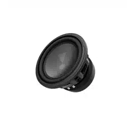
OVERVIEW - IRX115S
Thank you for purchase of the JBL IRX115S Powered Subwoofer
The IRX115S is the perfect pairing for the IRX108BT or IRX112BT powered loud speakers. The IRX115S draws from JBL’s
top professional touring technologies to deliver superior sound without the guesswork, thanks to custom driver and amplifier
designs, a tuned, ported enclosure and built-in crossover and polarity settings.
It all adds up to an impressive 128 dB of deep, powerful bass, in a rugged, lightweight cabinet to help bring 1300 watts of
massive low end to any live performance. With proper care your IRX115S should provide you with many years of flawless
performance, and JBL’s more than 70-year live sound legacy.
Powered 15” Subwoofer
• 1300 Watt
• 66 lb (34.5 kg)
• 128dB
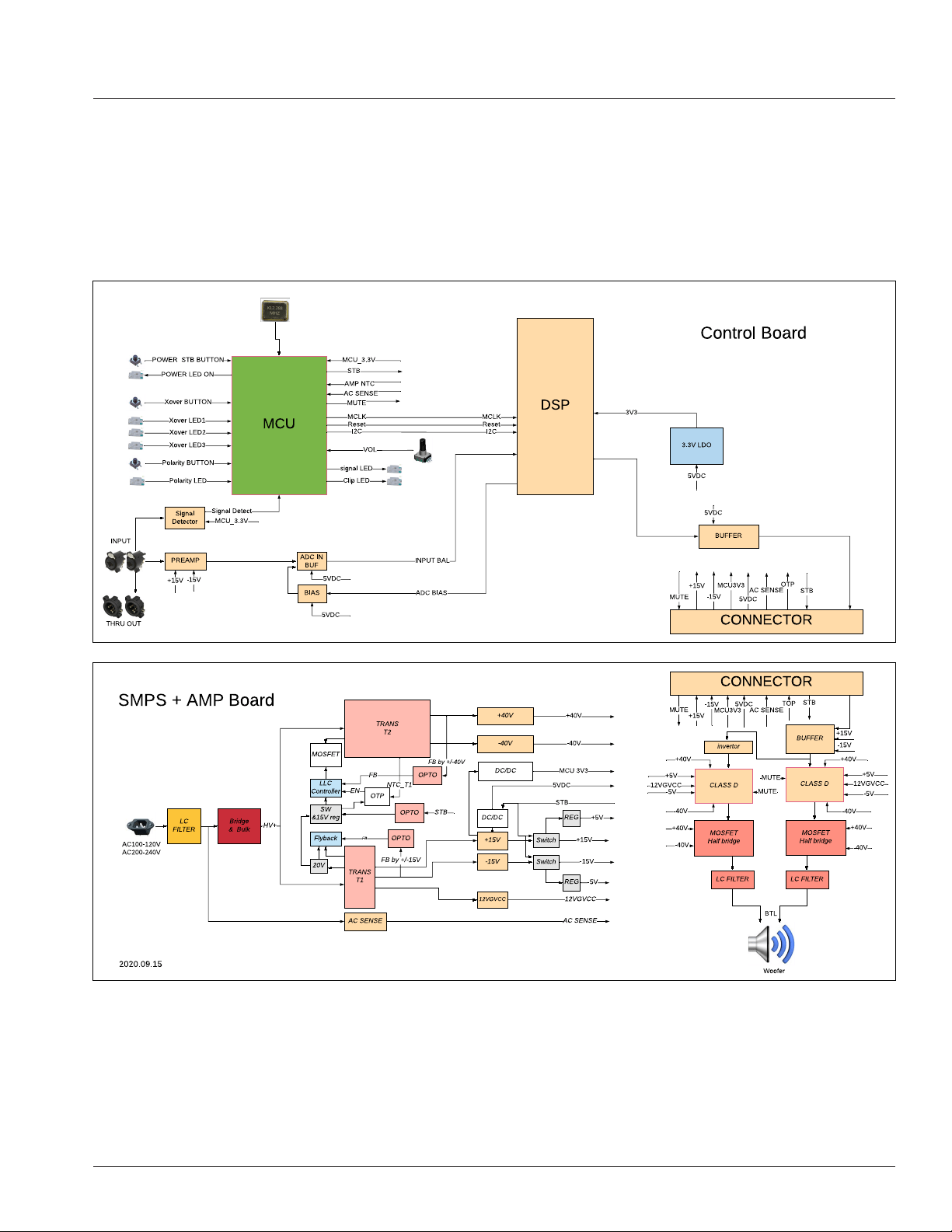
11
IRX115S - BLOCK DIAGRAM
12
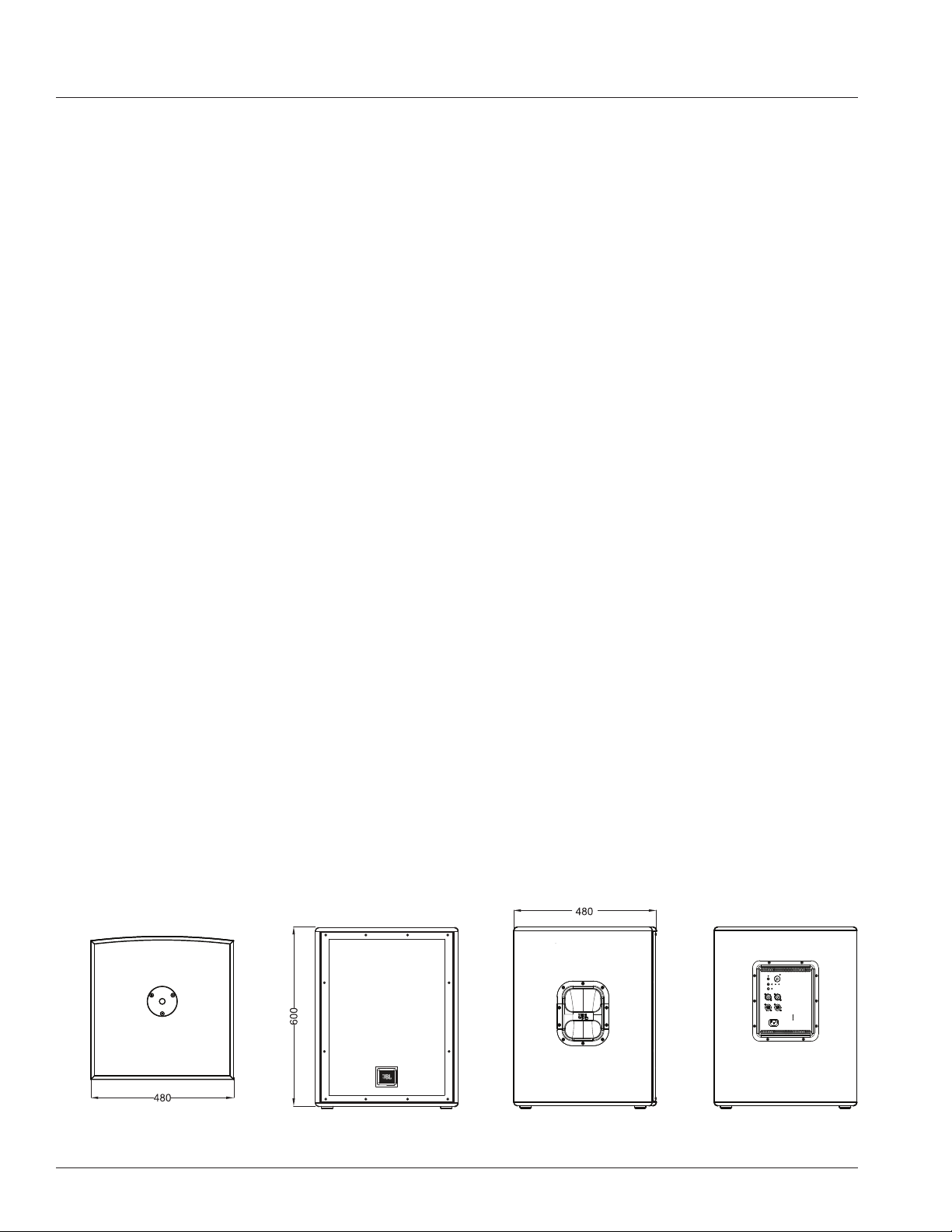
IRX115S SPECIFICATIONS
Top View Front View Left View Rear View
TECHNICAL SPECIFICATIONS
Freq Response (-3db) 45Hz - 103Hz
req Response (-10db) 35Hz - 147Hz
Wattage 1300W
Woofer Size 15”
Crossover Freq 80, 100, 120
Published (SPL) 128db
I/O 2 XLR combo, 2 XLR out
Cabinet MDF
Weight 34.5 kg / 76lbs
Pole Mount Yes

13
MUSICIANS/PERFORMERS
Musicians and performers looking for a great-sounding, easy-to-use sound reinforcement speaker in a portable, affordable package.
HOSPITALITY/GOVERNMENT INSTALLATIONS
Hospitality/government installations requiring professional sound quality with ease of use and minimal setup time.
FEATURES
• Powerful 15” woofer with 3” voicecoil generates smooth, detailed, deep LF response
• Selectable 80 Hz, 100 Hz and 120 Hz crossover points are optimized for JBL IRX Series loudspeakers
• Frequency response: 45Hz - 103Hz (-3 dB)
• Max SPL: 128 dB
• Weight: 76 pounds
• Power rating: 1,300W
• I/Os: 2 XLR Combo, 2 XLR out
• Polarity switch optimizes system response
• Lightweight, road-tested MDF cabinet
• Ported enclosure enhances output and reduces woofer noise
• Ergonomic handles make transport easy
• Reinforced grille offers rugged protection without compromising acoustic performance
• Built-in standard pole mount allows integration with IRX108BT, IRX112BT and other loudspeakers
APPLICATIONS / FEATURES
14
LOUDSPEAKER PLACEMENT AND SUSPENSION
The following guidelines will help you achieve optimum sound wherever you use your IRX115s
®
loudspeaker:
Raise the speakers as high as possible.
For best results try to get the high frequency horn at least 2 to 4 feet above the heads of the audience. If the speakers are too
low, the people in the back of the audience will not receive the best quality sound.
Place the speakers between the microphones and the audience.
Feedback occurs when the microphones pick up sound from the speakers and “feed” the sound back through the sound
system. If space is limited, point the speakers away from the microphones to reduce feedback.
Locate the speakers away from turntables.
Low-frequency feedback occurs when the output of the speaker is picked up by the tone arm of the turntable and is re-
amplified. A heavy, solid turntable base and shock mounting can also reduce this type of feedback in DJ applications.
Use more speakers in large or highly reverberant spaces.
Spreading speakers throughout these spaces will produce much better sound than trying to compensate with loudness level or
equalization. For very long distances, the use of another set of speakers with time delay is recommended.
Stand speakers upright for PA - Tilt the speakers back on the side for stage monitoring. Upright stance provides even coverage
over a wide area. IRX Series speakers are also designed with two slanted positions for stage monitoring applications.
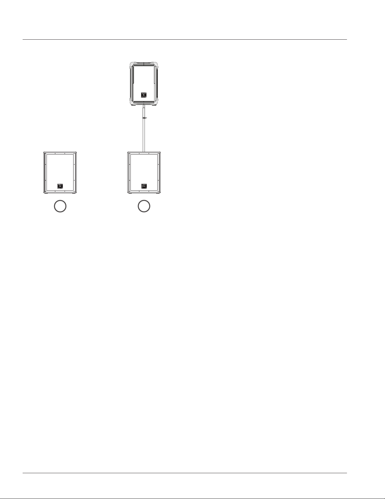
Floor Standing Subwoofer Mounted
1
2
15
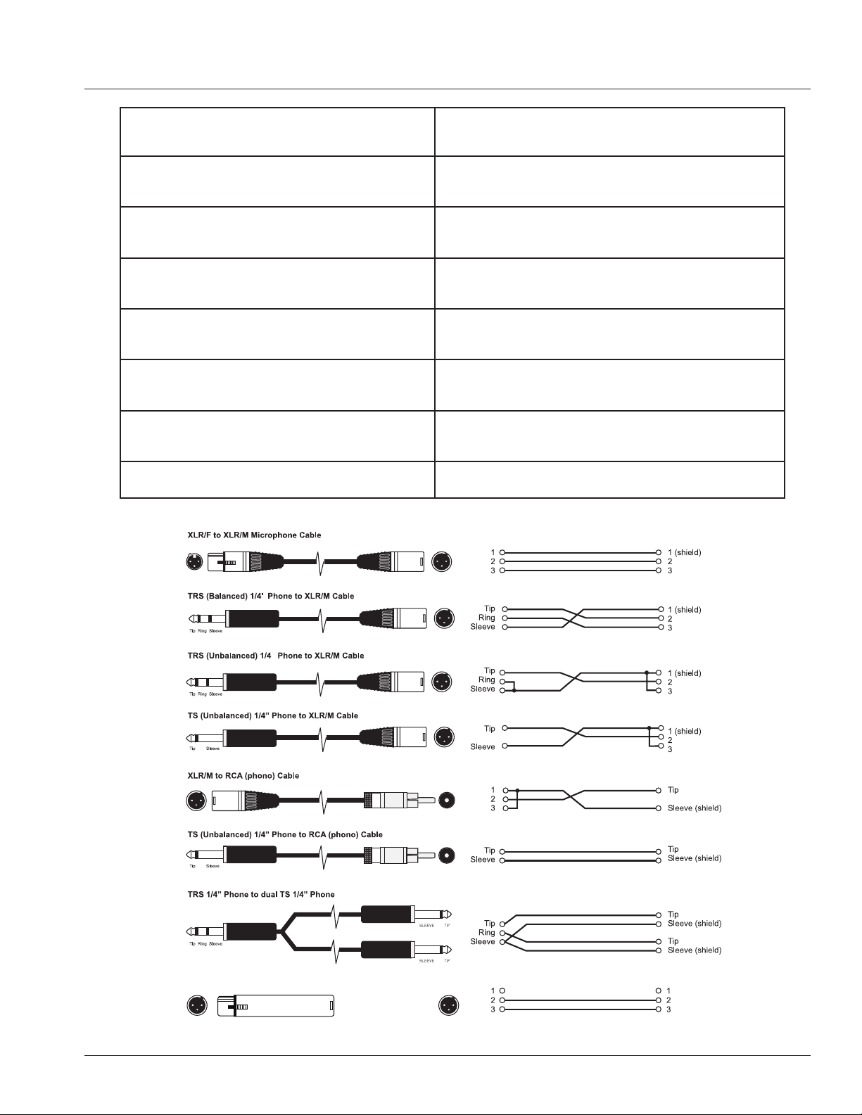
XLT/F to XLR/M Audio Groud Lift
(no connection)
XLR/F to XLR/M Microphone Cable
The standard cable for interconnection of microphone and
line level signal in professional audio systems.
• Microphone to mixer
TRS (balanced) 1/4 inch phone jack to XLR/M
For connecting balanced devices with 1/4 inch phone and
maybe used interchangeably.
TRS (unbalanced) 1/4 inch phone jack to XLR/M
For connections of instruments with unbalanced outputs
to balanced XLR inputs.
TS (unbalanced) 1/4 inch phone jack to XLR/M
This cable is electrically identical to "TRS" (unbalanced)
1/4 inch phone and may be used interchangeably.
XLR/M to RCA (phono) cable
Connects consumer audio products and some DJ mixer
outputs to professional audio equipment inputs
TRS 1/4 inch Phone jack to dual 1/4 inch Phone jack
Splits a stereo output into separate left/right signals.
TRS 1/4 inch Phone jack to dual 1/4 inch Phone jack
Change to a TRS mini-phone jack to connect to the output
of a portable. MP3/CD – player and computer sound cards
to a mixer.
XLR/F to XLR/M audio ground lift Only with balanced in - and outputs
CABLES & CONNECTORS
16
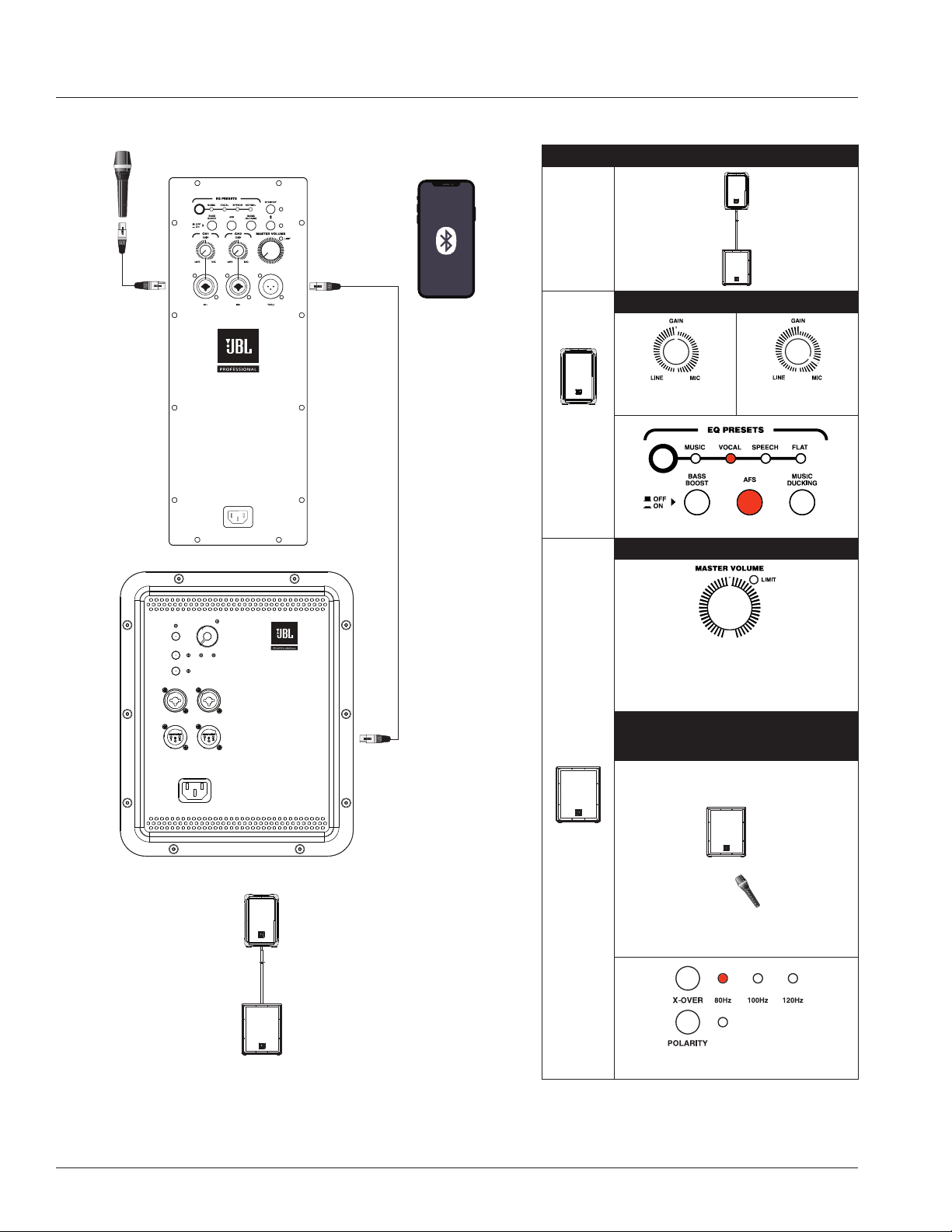
APPLICATION EXAMPLES
SMALL PA USING XLR AND BLUETOOTH
INPUTS AND THRU FUNCTION
CH1 XLR-1/4” Combo and
wirelss Bluetooth input to XLR-1/4” Thru
1+1 MODE RECOMMEDED SETTINGS
108BT or
112BT
Coupled
with
115s
Subwoofer
108BT /
112BT
CH 1/2
GAIN
LINE MICROPHONE
LINE MAX
position
AKG microphone
4 o’clock position
Preset to Vocals with AFS on
115s
Subwoofer
SUBWOOFER MASTER VOLUME
12 o’clock position
Besides these optimal setting, user(s) can continue to adjust
according to application or scenario, while referring to the
following microphone and subwoofer positioning distance to
prevent unnecessary feedback noise.
MICROPHONE
(presenter or speaker) Subwoofer
positioning distance
Microphone (speaker/presenter)
stands before subwoofer.
To prevent any unnecessary feedback, please:
Position Microphone at least 2m (6ft) from a speaker
Do not stand directly in front of a speaker
Crossover at 80Hz with Polarity off
17
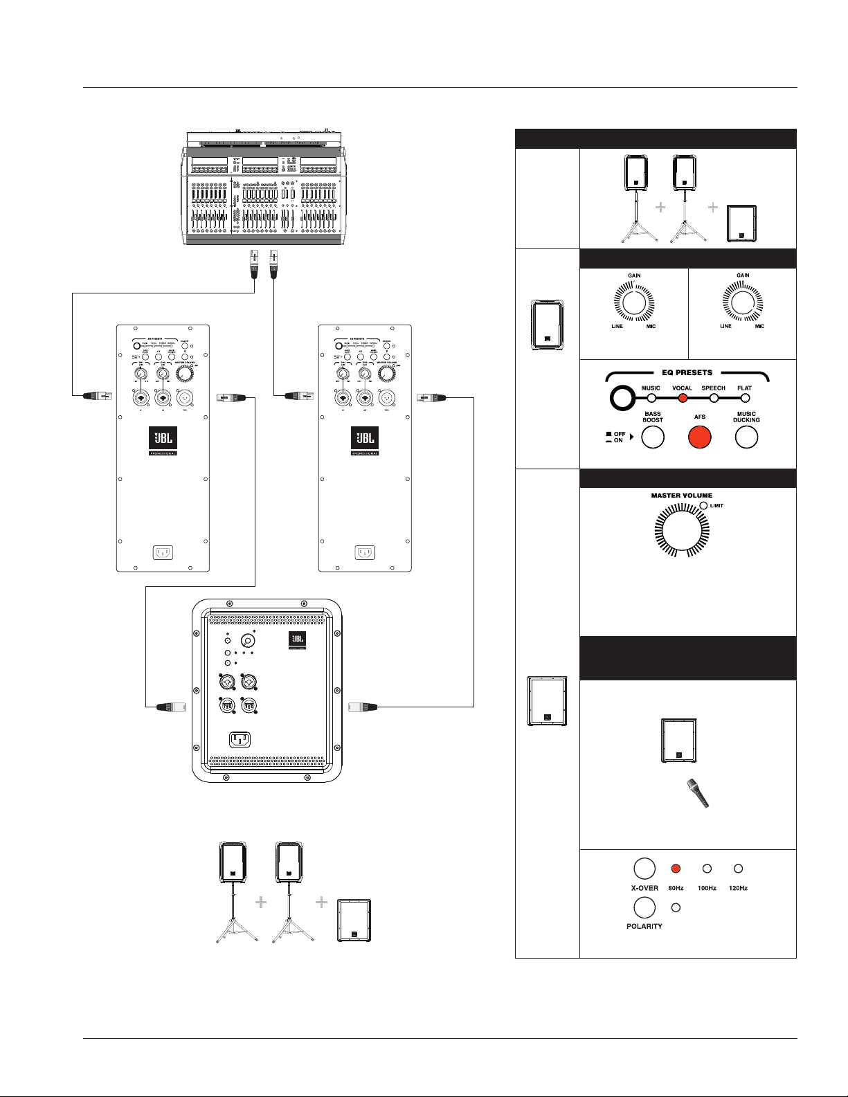
APPLICATION EXAMPLES
SMALL PA USING TWO SYSTEMS AS MONITORS
WITH SHARED THRU FUNCTION
PA1 and PA2 CH1 XLR-1/4” Combo inputs pass Thru to Sub
2+1 MODE RECOMMEDED SETTINGS
108BT or
112BT
Coupled
with
115s
Subwoofer
108BT /
112BT
CH 1/2
GAIN
LINE MICROPHONE
LINE MAX
position
AKG microphone
4 o’clock position
Preset to Vocals with AFS on
115s
Subwoofer
SUBWOOFER MASTER VOLUME
LIMIT LED position
(between 1 & 2 o’clock)
Besides these optimal setting, user(s) can continue to adjust
according to application or scenario, while referring to the
following microphone and subwoofer positioning distance to
prevent unnecessary feedback noise.
MICROPHONE
(presenter or speaker) Subwoofer
positioning distance
Microphone (speaker/presenter)
stands before subwoofer.
To prevent any unnecessary feedback, please:
Position Microphone at least 2m (6ft) from a speaker
Do not stand directly in front of a speaker
Crossover at 80Hz with Polarity off

18
APPLICATION EXAMPLES
SMALL PA USING TWO SYSTEMS AS MONITORS USING THRU FUNCTIONS
PA1 and PA2 CH1 XLR-1/4” Combo inputs pass Thru to individual Subs

19
Symptom Likely Cause What to do
No sound
Speaker not connected
to active AC power
Verify that speaker is connected and that the circuit is on
Power not switched on Switch on power and verify that power LED is on
Speaker in bypass mode Twist any knob or press the bypass button to wake the speaker.
No sound, speaker is connected
to working AC power but won’t
come on.
Speaker power cable is faulty
or improperly connected.
• Re-seat the power cable at both ends.
• Substitute a known-good power cable
No sound. Speaker comes on.
Signal source
(mixer, instrument, etc.)
is not sending.
• Check VU meters on the source mixer
• Verify that the tape or CD is playing.
• Use headphones to verify that the instrument is actually
sending an audio signal
Faulty cables and
connections
• Disconnect and re-seat signal cables.
• Replace suspected cable with a known-good cable
No sound with microphone
connected directly to the
MIC/ LINE input.
Microphone requires
phantom power
IRX115S is not set up for microphone levels. Please use a mixer, or run
out of the pass through of an IRX108BT or IRX112BT.
Signal sounds distorted and
very loud, PEAK light is lit
most of the time.
Excessive input signal, trying
to exceed the capabilities of
the speakers
• Reduce the output level of the source.
• Turn down the level controls on the speaker.
• Use additional VE speakers.
Signal sounds distorted even at
moderate volumes, LIMIT light
is not lit.
Mixer or other source
is overdriven
Review the Owner’s Manual for your mixer and adjust controls as needed.
• Input sensitivity (gain)
• Channel faders
• Master faders Once this is done, review the instructions in the Quick
Start section of this guide.
Lots of hiss in the sound,
the mixer controls are at
very low settings.
Improper gain structure
• Make sure that the MIC/LINE switch is in the LINE (disengaged) position.
• Mic/Line switch operation will be a little different.
• Reduce the level settings at speaker. Review the Owner’s Manual for
your mixer and adjust controls as needed.
• Input sensitivity (gain)
• Channel faders
• Master faders
Noise or hiss heard at output. Noisy source device
Disconnect the devices that are connected to your speaker one at a time.
If the noise goes away, the problem is with the source or the
connecting cable.
Hum or Buzz that increases or
decreases when the mixer level
controls are moved.
Improper A/C ground or
faulty equipment connected
to mixer input
Disconnect or mute channels one at a time to isolate the problem. Refer to
the owner’s manual of the faulty equipment for troubleshooting help.
Faulty cable between source
equipment and mixer
Substitute a known-good cable for the suspected faulty cable.
Hum or Buzz
Improper A/C grounding,
ground loops
• ‘Lift’ the audio ground by using an XLR/F to XLR/M adapter on one end.
• Re-route audio cables away from AC power and lighting cables.
Excessively long
unbalanced cable run
• Use the balanced outputs (if available) of your mixer or source
equipment to drive your IRX115s.
• Use a “DI” (direct injection) box to convert your unbalanced equipment
output to a balanced output.
Improper system gain
structure
Reduce the INPUT level controls and increase the output level of your
source devices.
TROUBLE SHOOTING

20
The JBL Limited Warranty on professional loudspeaker products (except for enclosures) remains in effect for five years from the
date of the first consumer purchase. JBL amplifiers are warranted for three years from thedate of original purchase. Enclosures
and all other JBL products are warranted for two years from the date of original purchase.
Who Is Protected By This Warranty?
Your JBL Warranty protects the original owner and all subsequent owners so long as: A.) Your JBL product has been purchased
in the Continental United States, Hawaii or Alaska. (This Warranty does not apply to JBL products purchased elsewhere except
for purchases by military outlets. Other purchasers should contact the local JBL distributor for warranty information.); and B.)
The original dated bill of sale is presented whenever warranty service is required.
What Does The JBL Warranty Cover?
Except as specified below, your JBL Warranty covers all defects in material and workmanship. The following are not covered:
Damage caused by accident, misuse, abuse, product modification or neglect; damage occurring during shipment; damage
resulting from failure to follow instructions contained in your Instruction Manual; damage resulting from the performance of
repairs by someone not authorized by JBL; claims based upon any misrepresentations by the seller; any JBL product on which
the serial number has been defaced, modified or removed.
Who Pays For What?
JBL will pay all labor and material expenses for all repairs covered by this warranty. Please be sure to save the original shipping
cartons because a charge will be made if replacement cartons are requested. Payment of shipping charges is discussed in the
next section of this warranty.
How To Obtain Warranty Performance
If your JBL product ever needs service, write or telephone us at JBL Incorporated (Attn: Customer Service Department), 8500
Balboa Boulevard, PO. Box 2200, Northridge, California 91329 (818/893-8411). We may direct you to an authorized JBL
Service Agency or ask you to send your unit to the factory for repair. Either way, you’ll need to present the original bill of sale to
establish the date of purchase. Please do not ship your JBL product to the factory without prior authorization. If transportation
of your JBL product presents any unusual difficulties, please advise us and we may make special arrangements with you.
Otherwise, you are responsible for transporting your product for repair or arranging for its transportation and for payment of any
initial shipping charges. However, we will pay the return shipping charges if repairs are covered by the warranty.
Limitation of Implied Warranties
ALL IMPLIED WARRANTIES, INCLUDING WARRANTIES OF MERCHANTABILITY AND FITNESS FOR PARTICULAR PURPOSE, ARE
LIMITED IN DURATION TO THE LENGTH OF THIS WARRANTY.
EXCLUSION OF CERTAIN DAMAGES
JBL’S LIABILITY IS LIMITED TO THE REPAIR OR REPLACEMENT, AT OUR OPTION, OF ANY DEFECTIVE PRODUCT AND SHALL
NOT INCLUDE INCIDENTAL OR CONSEQUENTIAL DAMAGES OF ANY KIND. SOME STATES DO NOT ALLOW LIMITATIONS ON
HOW LONG AN IMPLIED WARRANTY LASTS AND/OR DO NOT ALLOW THE EXCLUSION OF INCIDENTAL OR CONSEQUENTIAL
DAMAGES, SO THE ABOVE LIMITATIONS AND EXCLUSIONS MAY NOT APPLY TO YOU. THIS WARRANTY GIVES YOU SPECIFIC
LEGAL RIGHTS, AND YOU MAY ALSO HAVE OTHER RIGHTS, WHICH VARY, FROM STATE TO STATE.
JBL Professional
8500 Balboa Blvd. Northridge, CA 91329 USA
WARRANTY INFORMATION

21
Mailing Address:
JBL Professional
8500 Balboa Blvd.
Northridge, CA 91329
Shipping Address:
JBL Professional
8500 Balboa Blvd., Dock 15
Northridge, CA 91329
(Do not return product to this address without first obtaining prior authorization from JBL)
Customer Service:
Monday through Friday
8:00am -5:00pm
Pacific Coast Time in the U.S.A.
(800) 8JBLPRO (800.852.5776)
www.jblproservice.com
On The World Wide Web:
www.jblpro.com
Professional Contacts, Outside the USA:
Contact the JBL Professional Distributor in your area.
A complete list of JBL Professional international distributors is provided at our U.S.A. website: www.jblpro.com
CONTACT INFORMATION

10/20 8500 Balboa Boulevard Northridge, CA 91329 USA www.jblpro.com