Loading ...
Loading ...
Loading ...

15
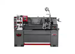
Power Indicator Light (A, Figure 9-1).
Illuminates whenever lathe is receiving
electrical current.
Coolant On-Off Switch (B, Figure 9-1).
Activates coolant pump.
Jog/Toggle Button (C, Figure 9-1). Quickly
press and release to briefly rotate spindle.
Emergency Stop Button (D, Figure 9-1).
Shuts down all machine functions. NOTE:
Lathe will still have power. Twist button
clockwise to reset.
Variable Speed Dial (E, Figure 9-1).
Adjust speed based upon range selected.
Dial may be turned while spindle is rotating.
Speed is displayed on LED screen (F).
2. Power Switch: Located at rear of left stand. “O”
is off, “I” is on. The switch has a lock-out hole
which will accept a padlock (not provided) to
prevent unauthorized use.
3. Inverter: Located at rear of cabinet toward
headstock side. Inverter enclosure can be
locked with the provided keys.
IMPORTANT: Do not attempt to adjust settings
on inverter. If you suspect a problem with the
inverter, contact JPW Technical Support for
instructions.
4. Speed Range Selector (G, Figure 9-1): Select
high or low range.
Do not move speed range
selector (G) while spindle is turning. Failure
to comply may damage lathe.
5. Feed Direction Lever (H, Figure 9-1): Select
direction of feed. Center position is neutral.
Do not move feed direction
lever (H) while spindle is turning. Failure to
comply may damage lathe.
6. Lead and Feed Selector Levers (J
1
/J
2
, Figure
9-1): Used conjunctively to set up for threading
or feeding, according to adjoining chart on front
of end cover. This chart is also reproduced in
sect. 13.0.
7. Carriage Lock (K, Figure 9-2): Turn clockwise
to lock, counterclockwise to unlock.
Carriage lock must be
released before engaging powerfeed.
Failure to comply may cause machine
damage.
8. Carriage Handwheel (L, Figure 9-2): Rotate to
manually move carriage assembly along
bedways. A scale is mounted to the ring,
graduated in 0.005 inch increments, and can be
calibrated by rotating the ring as needed.
Figure 9-2 (cutting tool not provided)
9. Feed Direction Knob (M, Figure 9-2): Push in
for left-to-right motion; pull out for right-to-left
motion.
10. Half Nut Lever (N, Figure 9-2): Engages
leadscrew for threading operations – down to
engage, up to disengage.
11. Spindle Direction Control Lever (O, Figure 9-
2). Move lever to the right so that its tab clears
the notch, then down for forward spindle
rotation, or up for reverse spindle rotation. Allow
spindle to come to a stop before changing
directions
.
Position lever in neutral position (tab
in notch) before shutting off lathe.
12. Power Feed Engagement Lever (P, Figure 9-
2): Engages powered operation. Push to one of
three positions: LEFT and UP for cross feed
operation (cross slide powered movement);
RIGHT and DOWN for longitudinal operation
(carriage powered movement); MIDDLE
position allows engagement of half nut for
threading.
13. Threading Dial (R, Figure 9-2): Indicates point
on leadscrew where half nut can be re-engaged
to continue inch threading.
14. Cross Slide Handwheel (S, Figure 9-2):
Clockwise rotation moves cross slide toward
rear of machine. The accompanying scale is
graduated in increments of 0.001 inch (0.0254
mm), and can be calibrated by rotating the ring
as needed.
15. Top Slide: Located atop cross slide (T, Figure
9-2); can be rotated 360° after loosening two
socket head screws (T
1
) in the circular base.
Calibrations in degrees at the base will assist
angle placement. Tighten screws (T
1
) before
operating.
Loading ...
Loading ...
Loading ...