Loading ...
Loading ...
Loading ...

10
Read and understand all
assembly instructions before attempting
assembly. Failure to comply may cause serious
injury.
6.0 Setup and assembly
6.1 Shipping contents
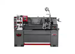
See Figure 6-1.
1 Lathe
1 Steady rest (pre-installed)
1 Follow rest (pre-installed)
1 Three jaw scroll chuck 6” (pre-installed)
1 Backplate 6” (150mm) (pre-installed)
1 Splash guard (pre-installed)
1 4-Position carriage stop (preinstalled)
6 Leveling pads (not shown)
1 Tool box (see contents below)
Tool box (p/n EVS1440B-TB) contents:
2 Open end wrenches (17/19, 12/14 mm)
1 Oil can
1 Hex key set (2, 2.5, 3, 4, 5, 6, 8 mm)
2 Shear pins
1 Set of change gears (50/46/44/40/35/30 T)
2 Chuck wrenches
1 Tool post wrench
2 Dead centers MT-3
1 Center sleeve MT-3/MT-5
1 Cross point screwdriver
1 Flat head screwdriver
2 Sets of keys for stand doors
1 Operating Instructions and Parts Manual
1 Product registration card
6.1.1 Optional accessories
The following accessories are available for the EVS-
1440B Lathe. See your dealer to order.
Taper attachment #892035
5C Collet closer #892006
12” Face Plate #E1440VS-FP02
Figure 6-1
6.2 Installation
1. Finish removing all crate material from around
lathe.
2. Unbolt lathe from shipping pallet.
3. Choose a location for the lathe that is dry and
has sufficient illumination (consult OSHA or
ANSI standards for recommended lighting
levels in workshop environments).
4. Allow sufficient room on all four sides for
servicing lathe, and to load and off-load work
pieces. In addition, if bar work is to be
performed, allow enough space for stock to
extend out the headstock end. If used in
production operations, leave enough space for
stacking unfinished and finished parts.
5. The foundation must be solid to support the
weight of the machine and prevent vibration,
preferably a solid concrete floor.
6. The lathe’s center of weight is near the
headstock. Before lifting, release tailstock and
carriage (see sect. 9.0 to locate locking levers)
to right end of bed and lock them.
Confirm that all suspension
equipment is properly rated and in good
condition for lifting lathe. Do not allow
anyone beneath or near load while lifting.
Loading ...
Loading ...
Loading ...