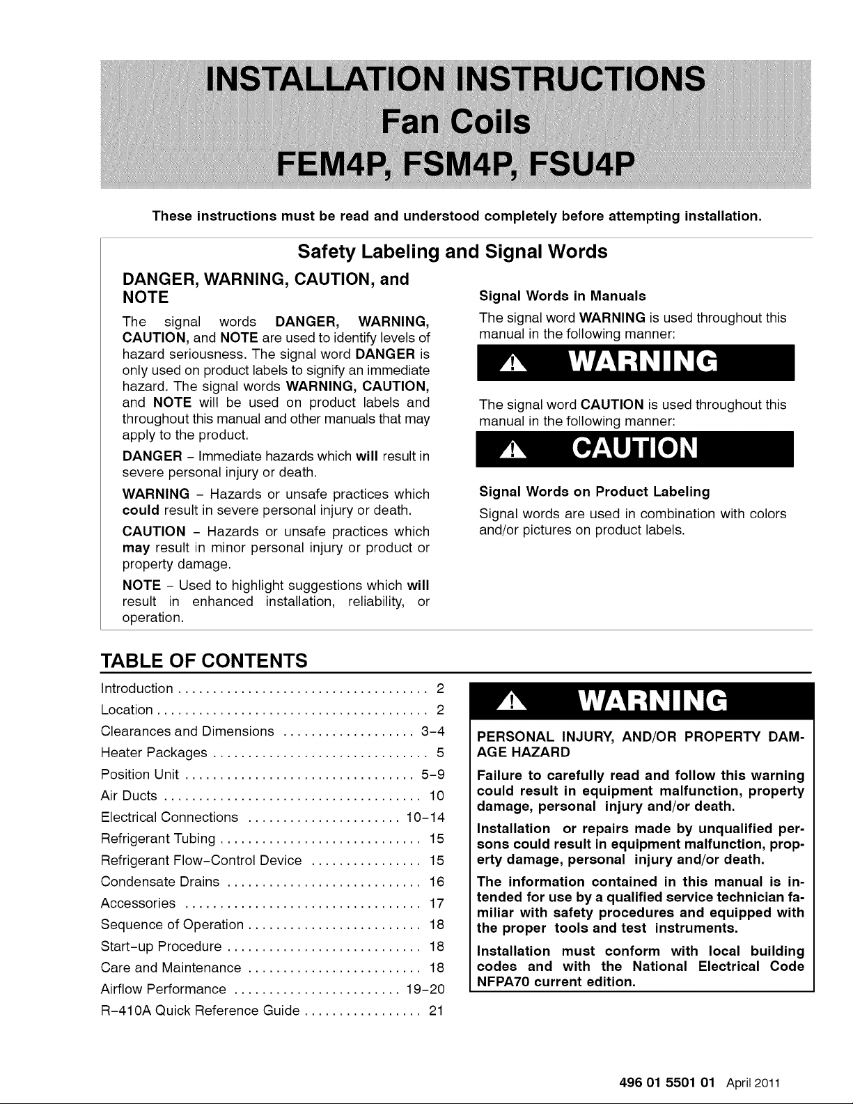
These
instructions
must
be
read
and
understood
completely
before
attempting
installation.
DANGER,
WARNING,
CAUTION,
and
NOTE
The
signal
words
DANGER,
WARNING,
CAUTION,
and
NOTE
are
used
to
identify
levels
of
hazard
seriousness.
The
signal
word
DANGER
is
only
used
on
product
labels
to
signify
an
immediate
hazard.
The
signal
words
WARNING,
CAUTION,
and
NOTE
will
be
used
on
product
labels
and
throughout
this
manual
and
other
manuals
that
may
apply
to
the
product.
DANGER
-
Immediate
hazards
which
will
result
in
severe
personal
injury
or
death.
WARNING
-
Hazards
or
unsafe
practices
which
could
result
in
severe
personal
injury
or
death.
CAUTION
-
Hazards
or
unsafe
practices
which
may
result
in
minor
personal
injury
or
product
or
property
damage.
NOTE
-
Used
to
highlight
suggestions
which
will
result
in
enhanced
installation,
reliability,
or
operation.
Safety
Labeling
and
Signal
Words
Signal
Words
in
Manuals
The
signal
word
WARNING
is
used
throughout
this
manual
in
the
following
manner:
4&
WARNING
The
signal
word
CAUTION
is
used
throughout
this
manual
in
the
following
manner:
4&
CAUTION
Signal
Words
on
Product
Labeling
Signal
words
are
used
in
combination
with
colors
and/or
pictures
on
product
labels.
TABLE
OF
CONTENTS
Introduction
..
00...
2c.
ee
eee
2
Location
0.0.0...
ee
eee
2
Clearances
and
Dimensions
................055
3-4
Heater
Packages
..........
0.0.0:
c
cece
ee
eee
5
Position
Unit...
0.0...
cee
eee
5-9
Ait
Ducts
2.0...
ee
10
Electrical
Connections
............
cee
eee
ee
10-14
Refrigerant
Tubing
...........0
0.0.0
eee
eee
eee
15
Refrigerant
Flow-Control
Device
...............5
15
Condensate
Drains
........
0.0...
cece
eee
ees
16
ACCESSOLICS
266.
17
Sequence
of
Operation.........
0...
cece
ee
ees
18
Start-up
Procedure
20...
..
0c
cece
eee
ees
18
Care
and
Maintenance
..............
eee
18
Airflow
Performance
..............0.0e
eevee
19-20
R-410A
Quick
Reference
Guide.................
21
7
aa
NS)
te
PERSONAL
INJURY,
AND/OR
PROPERTY
DAM-
AGE
HAZARD
Failure
to
carefully
read
and
follow
this
warning
could
result
in
equipment
malfunction,
property
damage,
personal
injury
and/or
death.
Installation
or
repairs
made
by
unqualified
per-
sons
could
result
in
equipment
malfunction,
prop-
erty
damage,
personal
injury
and/or
death.
The
information
contained
in
this
manual
is
in-
tended
for
use
by
a
qualified
service
technician
fa-
miliar
with
safety
procedures
and
equipped
with
the
proper
tools
and
test
instruments.
Installation
must
conform
with
local
building
codes
and
with
the
National
Electrical
Code
NFPA70
current
edition.
496
01
5501
01
April
2011

INTRODUCTION
Models
FEM4P,
FSM4P,
and
FSU4P
are
for
R-410A
refrigerant.
Models
FEM4P
and
FSM4P
are
designed
for
maximum
flexibility
and
can
be
used
for
upflow,
horizontal
left
or
right,
and
downflow
applications
(accessory
kit
required
for
downflow).
Model
FSU4P
is
designed
for
upflow
installation,
and
can
be
field
modified
for
downflow
applications
(accessory
kit
required).
LOCATION
FEM4P
models
are
available
for
system
sizes
1-1/2
-
4
tons
(18,000
-
48,000
BTUH)
nominal
cooling
capacity.
FEMA4P
uses
a
refrigerant
piston
metering
device
with
an
ECM
integral
electronically
commutated
motor
for
efficiency.
FSM4P
and
FSU4P
models
are
available
for
system
sizes
1-1/2
-
4
tons
(18,000
-
48,000
BTUH)
nominal
cooling
capacity.
FSM4P
and
FSU4P
use
a
refrigerant
piston
metering
device
with
2-speed
PSC
(permanent
split
capacitor)
motors.
All
models
require
a
field
supplied
air
filter.
Factory
approved
electric
heater
packages
are
available
in
sizes
5kW
through
30kW.
See
Product
Specification
literature
for
available
accessory
kits
Select
the
best
position
which
suits
the
installation
site
conditions.
The
location
should
provide
adequate
structural
support,
space
in
the
front
of
the
unit
for
service
access,
clearance
for
return
air
and
supply
duct
connections,
space
for
refrigerant
piping
connections
and
condensate
drain
line
connections.
If
heaters
are
being
installed
make
sure
adequate
clearance
is
maintained
from
supply
duct
work.
See
Clearances
in
Figure
1
and
Figure
2.
If
the
unit
is
located
in
an
area
of
high
humidity,
nuisance
sweating
of
casing
may
occur.
On
these
installations
a
wrap
of 2”
(51mm)
fiberglass
insulation
with
a
vapor
barrier
is
recommended.
NOTE:
Internal
filter
can
be
accessed
from
separate
filter
door.
If
the
filter
can
NOT
be
easily
accessed,
a
remote
filter
is
recommended.
Refer
to
ACCA
Manual
D for
remote
filter
sizing.
7
aN
Le
FIRE
HAZARD
Failure
to
maintain
proper
clearances
could
result
in
personal
injury,
death,
and/or
property
damage.
When
heaters
are
installed,
maintain
clearances
from
combustible
materials
as
specified
on
unit
rating
plate.
Do
not
use
plastic
lined
or
combustible
flexible
ducting
within
36
inches
of
the
supply
end
of
the
fan
coil.
496
01
5501
01
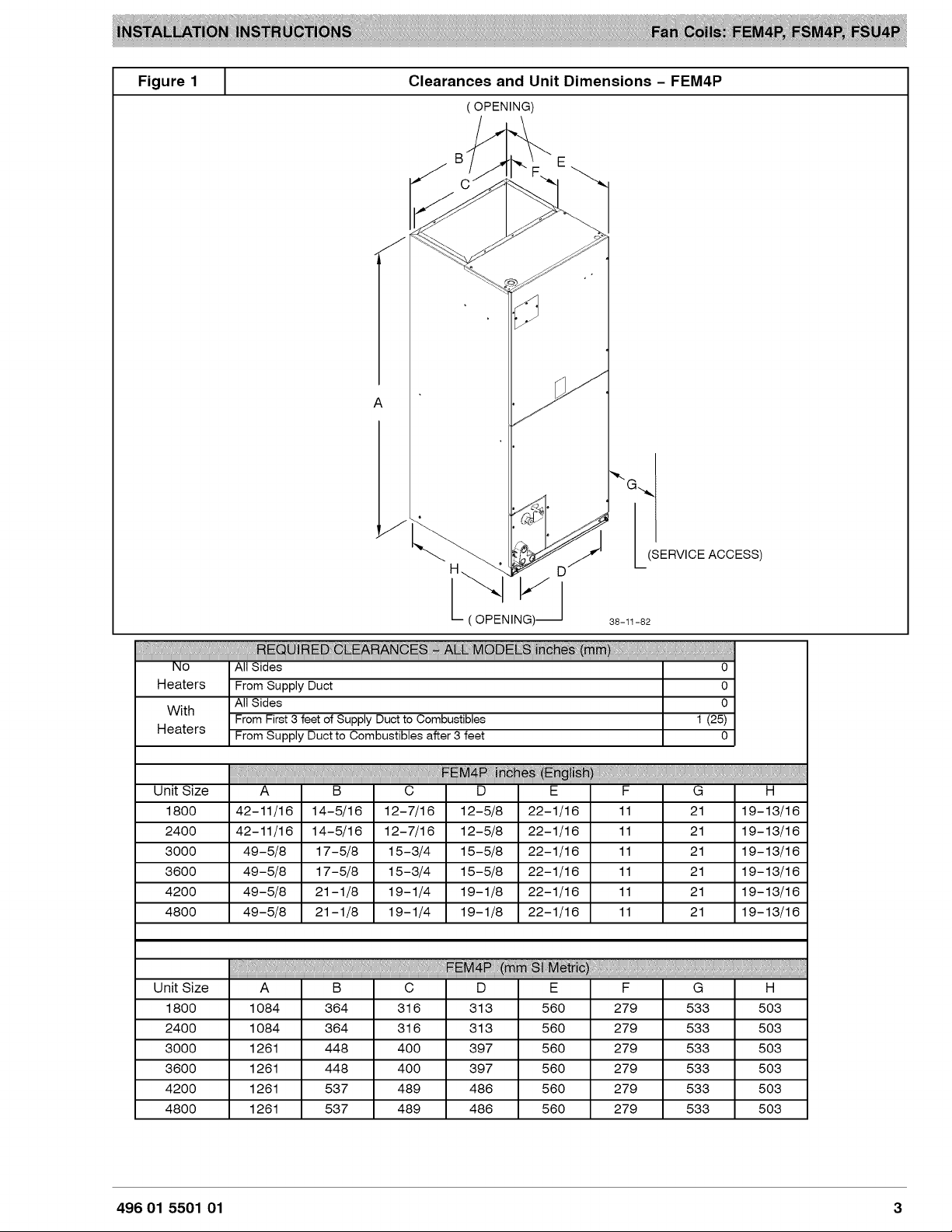
Figure
1
Clearances
and
Unit
Dimensions
-
FEM4P
(
OPENING)
(
mane]
(SERVICE
ACCESS)
38-11-82
Heaters
With
Heaters
Unit
Size
1800
2400
3000
3600
4200
4800
42-11/16
42-11/16
49-5/8
49-5/8
49-5/8
49-5/8
14-5/16
14-5/16
17-5/8
17-5/8
21-1/8
21-1/8
12-7/16
12-7/16
15-3/4
15-3/4
19-1/4
19-1/4
12-5/8
12-5/8
15-5/8
15-5/8
19-1/8
19-1/8
22-1/16
22-1/16
22-1/16
22-1/16
22-1/16
22-1/16
19-13/16
19-13/16
19-13/16
19-13/16
19-13/16
19-13/16
496
01
5501
01
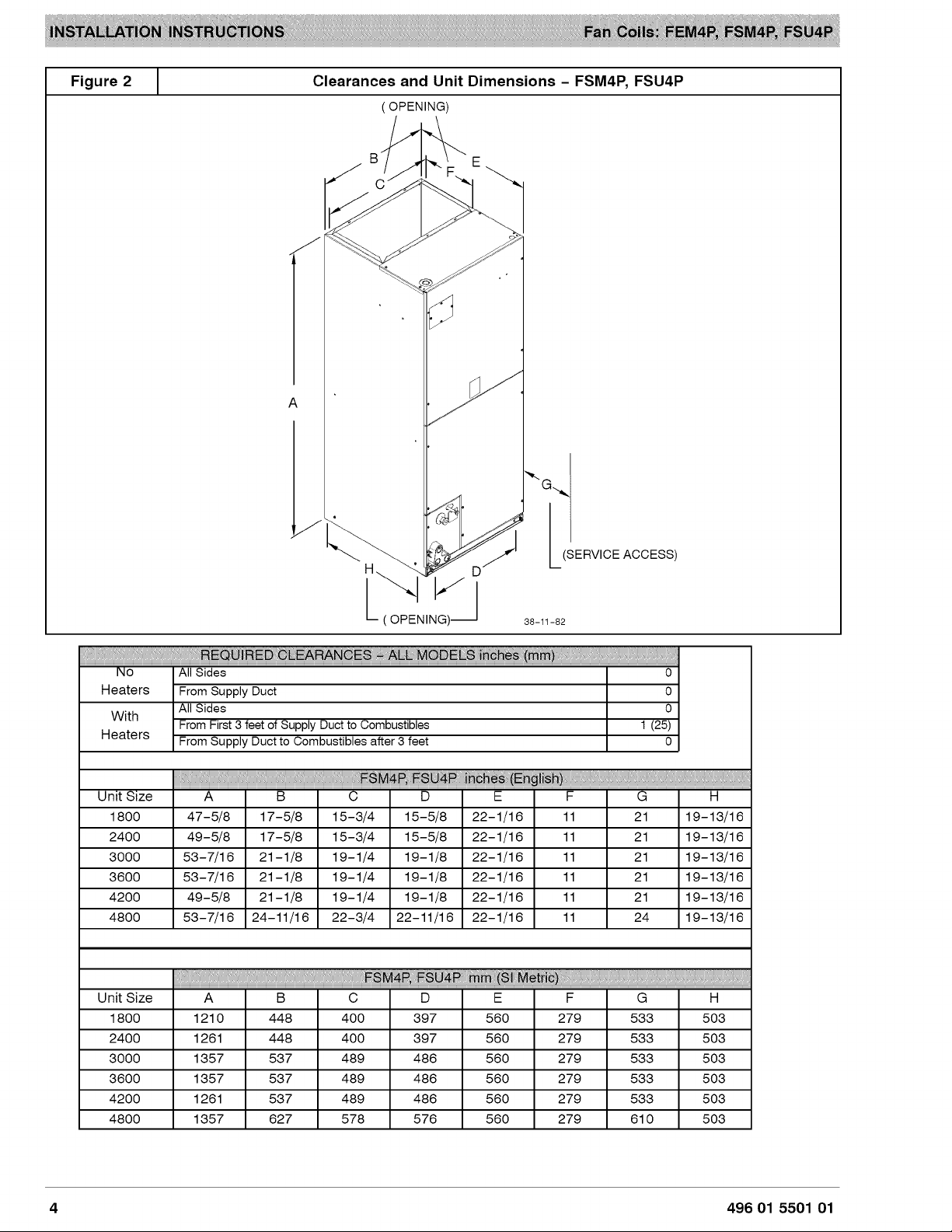
Figure
2
Clearances
and
Unit
Dimensions
—-
FSM4P,
FSU4P
(
OPENING)
(
mane]
(SERVICE
ACCESS)
38-11-82
Heaters
With
Heaters
47-5/8
49-5/8
53-7/16
53-7/16
49-5/8
53-7/16
Unit
Size
1800
2400
3000
3600
4200
4800
17-5/8
17-5/8
21-1/8
21-1/8
21-1/8
24-11/16
15-3/4
15-3/4
19-1/4
19-1/4
19-1/4
22-3/4
15-5/8
15-5/8
19-1/8
19-1/8
19-1/8
22-11/16
22-1/16
22-1/16
22-1/16
22-1/16
22-1/16
22-1/16
19-13/16
19-13/16
19-13/16
19-13/16
19-13/16
19-13/16
496
01
5501
01

HEATER
PACKAGES
Factory
approved,
field
installed,
UL
listed
heater
packages
are
available
from
the
equipment
supplier.
See
unit
rating
plate
for
a
list
of
factory
approved
heaters.
POSITION
UNIT
Unit
can
stand
or
lie
on
floor,
or
hang
from
ceiling
or
wall.
Allow
space
for
wiring, piping,
and
servicing
unit.
CAUTION
A
PROPERTY
DAMAGE
HAZARD
Failure
to
follow
this
caution
may
result
in
proper-
ty
damage
A
field
fabricated
auxiliary
drain
pan,
with
a
sepa-
rate
drain
is
REQUIRED
for
all
installations
over
a
finished
living
space
or
in
any
area
that
may
be
damaged
by
overflow
from
a
restricted
main
drain
pan.
In
some
localities,
local
codes
require
an
aux-
iliary
drain
pan
for
ANY
horizontal
installation.
Heaters
that
are
not
factory
approved
could
cause
damage
which
would
not
be
covered
under
the
equipment
warranty.
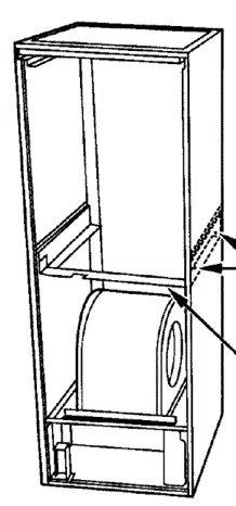
A.
UPFLOW
INSTALLATION
If
return
air
is
to
be
ducted
through
a
floor,
set
unit
on
floor
over
opening
and
use
1/8
to
1/4
inch thick
(3 to
6
mm
thick)
fireproof
resilient
gasket
between
duct,
unit,
and
floor.
Side
return
is
a
field
option
on
slope
coil
models.
Cut
opening
per
dimensions
shown
in
Figure3.
A
field-supplied
bottom
closure
is
required.
PRIMARY
DRAIN
Figure
3
Upflow
Installation
POWER
ENTRY
FIELD
SUPPLIED
OPTIONS
1
SUPPLY
DUCT
LOW
VOLT
ENTRY
OPTIONS
FRONT
SERVICE
CLEARANCE
‘
SLOPE
COIL
UNITS
18
—
48
models
=
21”
(533
mm)
—
|
°
60
model
=
24”
(610
mm)
Na
x
MODEL
SIZE
18
12"
(305mm)
‘A-COIL
UNITS
24
12"
(305mm)
30
17"
(432mm)
UPFLOW/DOWNFLOW~—
"
7
SECONDARY
DRAIN
1%
36
17"
(432mm)
\
,
|
UPFLOW/DOWNFLOW
|
Li
Lor
|
caeomm)
PRIMARY
DRAIN
°
pH
NL
“iI
FIELD
MODIFIED
| |
A
SIDERETURN
1
ow
ou.
LOCATION
FOR
1 |
2
SLOPE
COIL
(4mm)
UNITS
ONLY
UPFLOW/DOWNFLOW
|
J
SECONDARY
DRAIN
|
4
as
y
UPFLOW/DOWNFLOW
Ps
FIELD
SUPPLIED
RETURN PLENUM
496
01
5501
01
B.
DOWNFLOW
INSTALLATION
A
CAUTION
PRODUCT
OR
PROPERTY
DAMAGE
HAZARD
Failure
to
follow
this
caution
may
result
in
product
or
property
damage
The
conversion
of
the
fan
coil
to
downflow
re-
quires
special
procedures
for
the
condensate
drains
on
both
A-coil
and
Slope-coil
units.
The
vertical
drains
have
an
overflow
hole
between
the
primary
and
secondary
drain
holes.
This
hole
is
plugged
for
all
applications
except
downflow,
and
must
be
used
for
downflow.
Failure
to
follow
instructions
could
result
in
per-
sonal
injury
or
product
and
property
damage.
In
this
application,
field
conversion
of
the
evaporator
coil
is
required
using
accessory
Downflow
Kit
along
with
an
accessory
Base
Kit.
Set
unit
on
floor
over
opening
and
use
1/8”
to
1/4”
thick
fireproof
resilient
gasket
between
duct,
unit,
and
floor.
Refer
to
installation
instructions
packaged
with
accessory
kit.
See
Product
Specification
literature
for
kit
part
numbers.
During
the
conversion
process,
removed
the
plastic
cap
covering
the
vertical
drains
only
and
discard.
Remove
the
plug
from
the
overflow
hole
and
discard.
At
completion
of
the
downflow
installation,
caulk
around
the
vertical
pan
fitting
to
door
joint
to
retain
low
air
leak
performance
of
the
unit.
NOTE:
Gasket
kit
number
(EBACO1GSK)
is
also
required
for
all
downflow
applications
to
maintain
low
air
leak/low
sweat
performance.
C.
HORIZONTAL
INSTALLATION
Unit
must
NOT
be
installed
with
access
panels
facing
up
or
down.
Access
panels
must
only
face
to
the
side.
FEM4P
and
FSM4P
models
are
factory
built
for
horizontal
left
installation
(refer
to
Figure
4
and
Figure
5).
They
can
be
field
converted
to
horizontal
right
(accessory
Gasket
Kit
required,
see
Product
Specification
literature
for
part
number).
Refer
to
Figure
6
and
Figure
7.
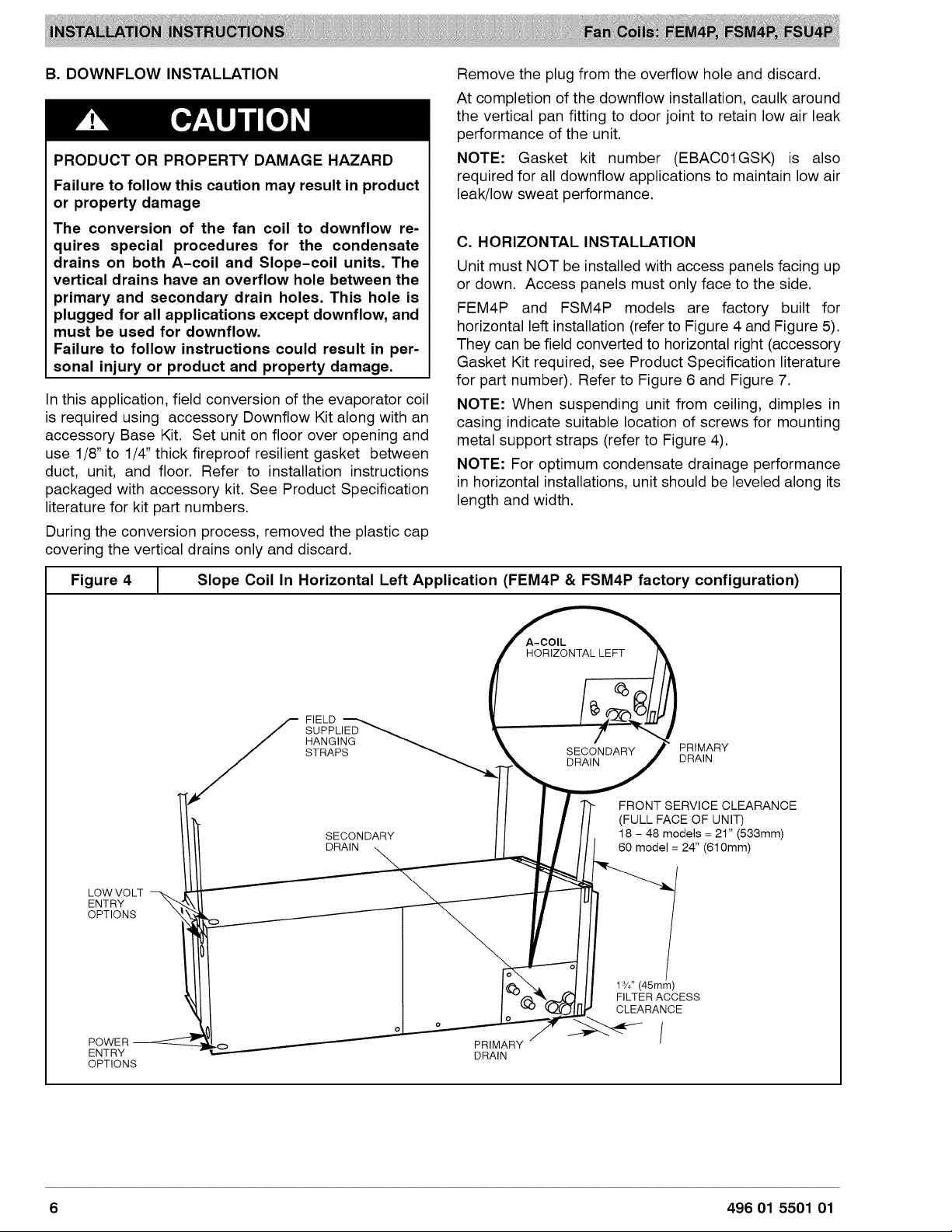
NOTE:
When
suspending
unit
from
ceiling,
dimples
in
casing
indicate
suitable
location
of
screws
for
mounting
metal
support
straps
(refer
to
Figure
4).
NOTE:
For
optimum
condensate
drainage
performance
in
horizontal
installations,
unit
should
be
leveled
along
its
length
and
width.
Figure
4
Slope
Coil
In
Horizontal
Left
Application
(FEM4P
&
FSM4P
factory
configuration)
A-COIL
HORIZONTAL
LEFT
FIELD
SUPPLIED
HANGING
PRIMARY
STRAPS
SECONDARY
aye
FRONT
SERVICE
CLEARANCE
(FULL
FACE
OF
UNIT)
SECONDARY
18
-
48
models
=
21”
(633mm)
DRAIN
60
model
=
24”
(610mm)
Sf
ES
LOW
VOLT
mT
ENTRY
XY
/
OPTIONS
y=
\
i
0
oO
@
1%”
(45mm)
@
SC)
FILTER
ACCESS
VN
OCI
CLEARANCE
Oo
\
2
a
POWER
=
PRIMARY
ENTRY
DRAIN
OPTIONS
496
01
5501
01
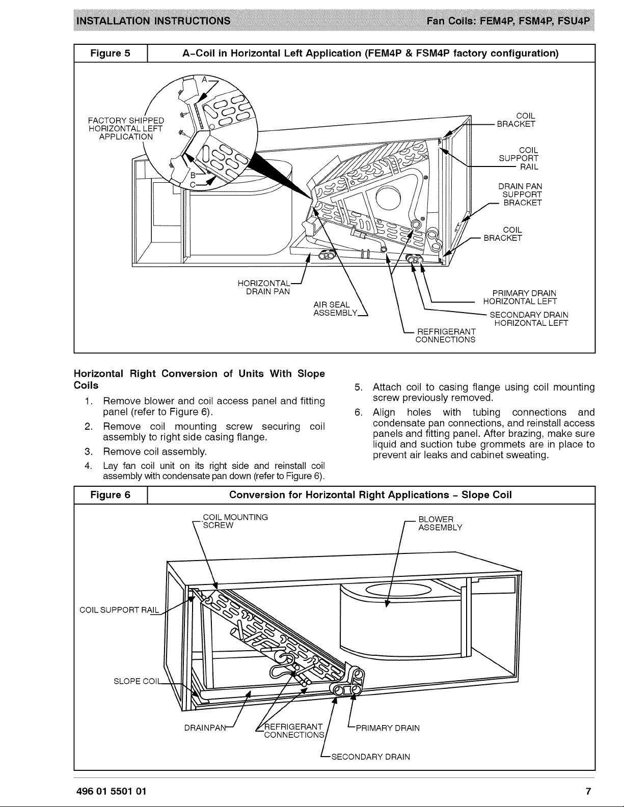
Figure
5
A-Coil
in
Horizontal
Left
Application
(FEM4P
&
FSM4P
factory
configuration)
FACTORY
SHIPPED
HORIZONTAL
LEFT
APPLICATION
COIL
BRACKET
OK
Cahn
COIL
SUPPORT
RAIL
DRAIN
PAN
SUPPORT
I
a
BRACKET
COIL
BRACKET
sorwonta.t
DRAIN
PAN
AIR
SEAL
ASSEMBLY
PRIMARY
DRAIN
HORIZONTAL
LEFT
SECONDARY
DRAIN
HORIZONTAL
LEFT
REFRIGERANT
CONNECTIONS
Horizontal
Right
Conversion
of
Units
With
Slope
Coils
1.
Remove
blower
and
coil
access
panel
and
fitting
panel
(refer
to
Figure
6).
2.
Remove
coil
mounting
screw
securing
coil
assembly
to
right
side
casing
flange.
3.
Remove
coil
assembly.
4.
Lay
fan
coil
unit
on
its
right
side
and
reinstall
coil
assembly
with
condensate
pan
down
(refer
to
Figure
6).
Attach
coil
to
casing
flange
using
coil
mounting
screw
previously
removed.
Align
holes
with
tubing
connections
and
condensate
pan
connections,
and
reinstall
access
panels
and
fitting
panel.
After
brazing,
make
sure
liquid
and
suction
tube
grommets
are
in
place
to
prevent
air
leaks
and
cabinet
sweating.
Figure
6
Conversion
for
Horizontal
Right
Applications
-
Slope
Coil
COIL
MOUNTING
BLOWER
“SCREW
|
ASSEMBLY
Ss
COIL
SUPPORT
RAIL
,
SS
SS
Ss
2)
NS
2
LQS\/H
SLOPE
COl
IS
Ox
DRAINPA
EFRIGERANT
PRIMARY
DRAIN
CONNECTIONS
SECONDARY
DRAIN
496
01
5501
01
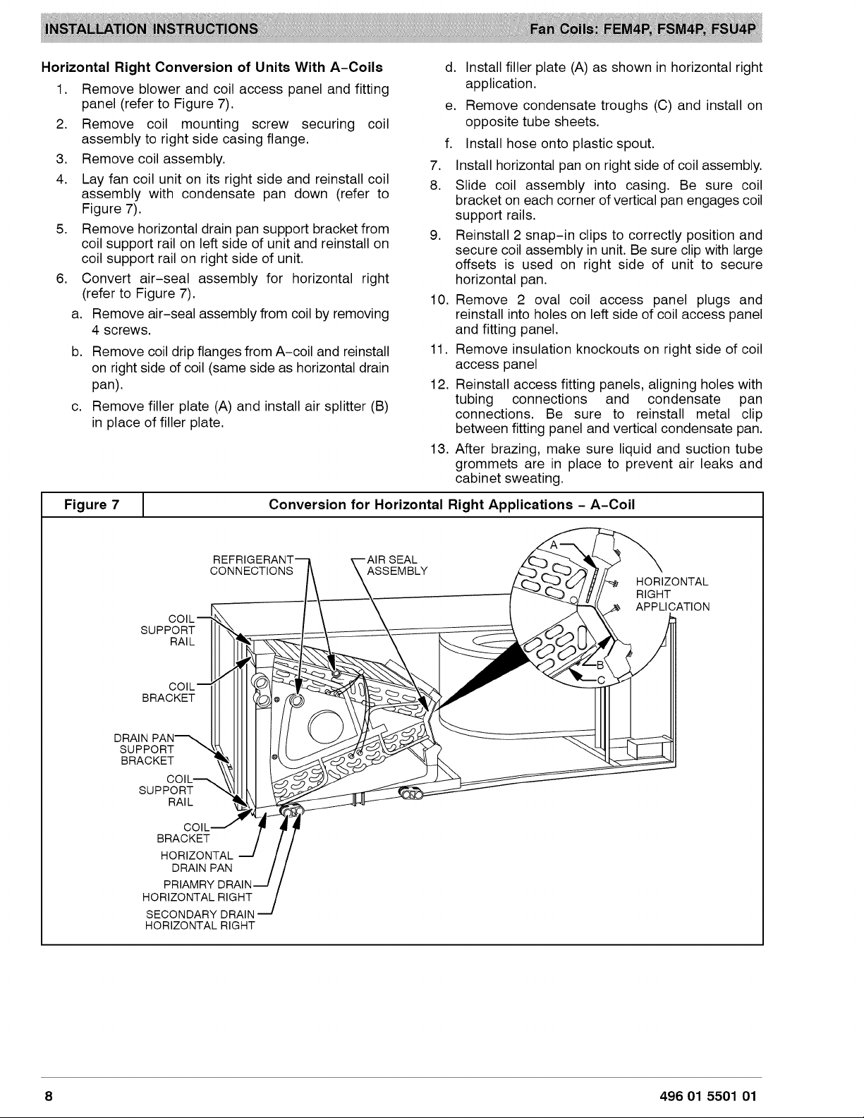
Horizontal
Right
Conversion
of
Units
With
A-Coils
d.
Install
filler
plate
(A)
as
shown
in
horizontal
right
1.
Remove
blower
and
coil
access
panel
and
fitting
application.
panel
(refer
to
Figure
7).
e,
Remove
condensate
troughs
(C)
and
install
on
2.
Remove
coil
mounting
screw
securing
coil
opposite
tube
sheets.
assembly
to
right
side
casing
flange.
f.
Install
hose
onto
plastic
spout.
3.
Remove
coil
assembly.
7.
Install
horizontal
pan
on
right
side
of
coil
assembly.
4.
Lay
fan
coil
unit
on
its
right
side
and
reinstall
coil
8.
Slide
coil
assembly
into
casing.
Be
sure
coil
assemby
with
condensate
pan
down
(refer
to
bracket
on
each
corner
of
vertical
pan
engages
coil
igure
7).
support
rails.
5.
Remove
horizontal
drain
pan
support
bracket
from
9.
Reinstall
2
snap-in
clips
to
correctly
position
and
coil
support
rail
on
left
side
of
unit
and
reinstall
on
coil
support
rail
on
right
side
of
unit.
secure
coil
assembly
in
unit.
Be
sure
clip
with
large
offsets
is
used
on
right
side
of
unit
to
secure
6.
Convert
air-seal
assembly
for
horizontal
right
horizontal
pan.
(refer
to
Figure
7).
10.
Remove
2
oval
coil
access
panel
plugs
and
a.
Remove
air-seal
assembly
from
coil
by
removing
reinstall
into
holes
on
left
side
of
coil
access
panel
4
screws.
and
fitting
panel.
b.
Remove
coil
drip
flanges
from
A-coil
and
reinstall
11.
Remove
insulation
knockouts
on
right
side
of
coil
on
right
side
of
coil
(same
side
as
horizontal
drain
access
panel
pan).
12.
Reinstall
access
fitting
panels,
aligning
holes
with
tubing
connections
and
condensate
pan
connections.
Be
sure
to
reinstall
metal
clip
between
fitting
panel
and
vertical
condensate
pan.
13.
After
brazing,
make
sure
liquid
and
suction
tube
grommets
are
in
place
to
prevent
air
leaks
and
cabinet
sweating.
c.
Remove
filler
plate
(A)
and
install
air
splitter
(B)
in
place
of
filler
plate.
Figure
7
Conversion
for
Horizontal
Right
Applications
-
A-Coil
REFRIGERANT
AIR
SEAL
CONNECTIONS
\
\
ASSEMBLY
coi_—
support
|X.
___
RAIL
COIL
BRACKET
DRAIN
PAN
SUPPORT
\Q
BRACKET
.
COIL
\
supronT
N\I
RAIL
con—™”
BRACKET
HORIZONTAL
DRAIN
PAN
PRIAMRY
DRAIN
HORIZONTAL
RIGHT
SECONDARY
DRAIN
HORIZONTAL
RIGHT
HORIZONTAL
RIGHT
APPLICATION
8
496
01
5501
01
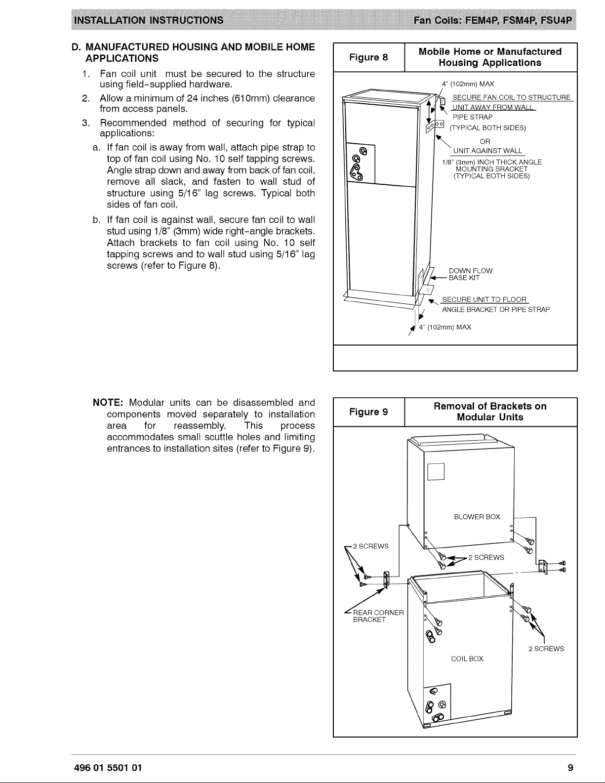
D.
MANUFACTURED
HOUSING
AND
MOBILE
HOME
APPLICATIONS
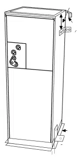
1.
2.
a.
Fan
coil
unit
must
be
secured
to
the
structure
using
field—supplied
hardware.
Allow
a
minimum
of
24
inches
(610mm)
clearance
from
access
panels.
Recommended
method
of
securing
for
typical
applications:
If
fan
coil
is
away
from
wall,
attach
pipe
strap
to
top
of
fan
coil
using
No.
10
self
tapping
screws.
Angle
strap
down
and
away
from
back
of
fan
coil,
remove
all
slack,
and
fasten
to
wall
stud
of
structure
using
5/16”
lag
screws.
Typical
both
sides
of
fan
coil.
If
fan
coil
is
against
wall,
secure
fan
coil
to
wall
stud
using
1/8”
(8mm)
wide
right-angle
brackets.
Attach
brackets
to
fan
coil
using
No.
10
self
tapping
screws
and
to
wall
stud
using
5/16”
lag
screws
(refer
to
Figure
8).
NOTE:
Modular
units
can
be
disassembled
and
components
moved
separately
to
installation
area
for
reassembly.
This
process
accommodates
small
scuttle
holes
and
limiting
entrances
to
installation
sites
(refer
to
Figure
9).
Figure
8
Mobile
Home
or
Manufactured
Housing
Applications
4”
(102mm)
MAX
aa
SECURE
FAN
COIL
TO
STRUCTURE
UNIT
AWAY
FROM
WALL
PIPE
STRAP
°
eo]
(TYPICAL
BOTH
SIDES)
OR
UNIT
AGAINST
WALL
1/8”
(8mm)
INCH
THICK
ANGLE
MOUNTING
BRACKET
(TYPICAL
BOTH
SIDES)
DOWN
FLOW
BASE
KIT
ww,
SECURE
UNIT
TO
FLOOR
y
ANGLE
BRACKET
OR
PIPE
STRAP
4”
(102mm)
MAX
Figure
9
Removal
of
Brackets
on
Modular
Units
REAR
CORNER
BRACKET
BLOWER
BOX
2
SCREWS
496
01
5501
01
AIR
DUCTS
Connect
supply-air
duct
over
the
outside
of
%”
flanges
provided
on
supply-air
opening.
Secure
duct
to
flange
using
proper
fasteners
for
type
of
duct
used,
and
seal
duct-to-unit
joint.
Use
flexible
connectors
between
duct
work
and
unit
to
prevent
transmission
of
vibration.
When
electric
heater
is
installed,
use
heat-resistant
material
for
flexible
connector
between
duct
work
and
unit
at
discharge
connection.
Duct
work
passing
through
unconditioned
space
must
be
insulated
and
covered
with
vapor
barrier.
ELECTRICAL
CONNECTIONS
Duct
work
Acoustical
Treatment
Metal
duct
systems
that
do
not
have
a
90
degree
elbow
and
10
feet
of
main
duct
before
first
branch
takeoff
may
require
internal
acoustical
insulation
lining.
As
an
alternative,
fibrous
duct
work
may
be
used
if
constructed
and
installed
in
accordance
with the
latest
edition
of
SMACNA
construction
standard
on
fibrous glass
ducts.
Both
acoustical
lining
and
fibrous
duct
work
shall
comply
with
National
Fire
Protection
Association
as
tested
by
UL
Standard
181
for
Class
1
air
ducts.
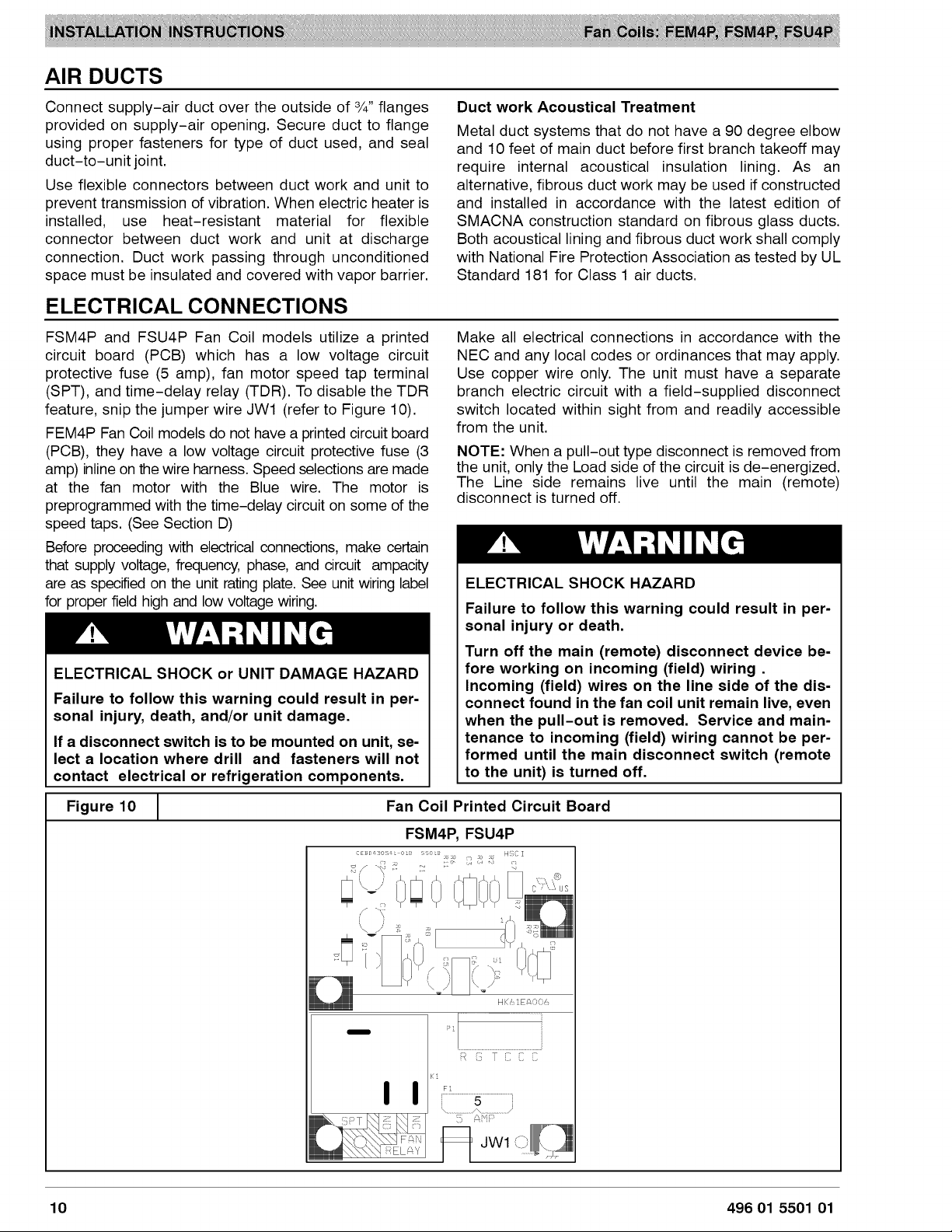
FSM4P
and
FSU4P
Fan
Coil
models
utilize
a
printed
circuit
board
(PCB)
which
has
a
low
voltage
circuit
protective
fuse
(5
amp),
fan
motor
speed
tap
terminal
(SPT),
and
time-delay
relay
(TDR).
To
disable
the
TDR
feature,
snip
the
jumper
wire
JW1
(refer
to
Figure
10).
FEM4P
Fan
Coil
models
do
not
have
a
printed
circuit
board
(PCB),
they
have
a
low
voltage
circuit
protective
fuse
(3
amp)
inline
on
the
wire
harness.
Speed
selections
are
made
at
the
fan
motor
with
the
Blue
wire.
The
motor
is
preprogrammed
with
the
time-delay
circuit
on
some
of
the
speed
taps.
(See Section
D)
Before
proceeding
with
electrical
connections,
make
certain
that
supply
voltage,
frequency,
phase,
and
circuit
ampacity
are
as
specified
on the
unit
rating
plate.
See
unit
wiring
label
for
proper
field
high
and
low
voltage
wiring.
7
aa
NS)
te
ELECTRICAL
SHOCK
or
UNIT
DAMAGE
HAZARD
Failure
to
follow
this
warning
could
result
in
per-
sonal
injury,
death,
and/or
unit
damage.
If
a
disconnect
switch
is
to
be
mounted
on
unit,
se-
lect
a
location
where
drill
and
fasteners
will
not
contact
electrical
or
refrigeration
components.
Make
all
electrical
connections
in
accordance
with the
NEC
and
any
local
codes
or
ordinances
that
may
apply.
Use
copper
wire
only.
The
unit
must
have
a
separate
branch
electric
circuit
with
a
field-supplied
disconnect
switch
located
within
sight
from
and
readily
accessible
from
the
unit.
NOTE:
When
a
pull-out
type
disconnect
is
removed
from
the
unit,
only
the
Load
side
of
the
circuit
is
de-energized.
The
Line
side
remains
live
until
the
main
(remote)
disconnect
is
turned
off.
7
aN
Le
ELECTRICAL
SHOCK
HAZARD
Failure
to
follow
this
warning
could
result
in
per-
sonal
injury
or
death.
Turn
off
the
main
(remote)
disconnect
device
be-
fore
working
on
incoming
(field)
wiring
.
Incoming
(field)
wires
on
the
line
side
of
the
dis-
connect
found
in
the
fan
coil
unit
remain
live,
even
when
the
pull-out
is
removed.
Service
and
main-
tenance
to
incoming
(field)
wiring
cannot
be per-
formed
until
the
main
disconnect
switch
(remote
to
the
unit)
is
turned
off.
Figure
10
Fan
Coil
Printed
Circuit
Board
10
496
01
5501
01
A.
LINE
VOLTAGE
CONNECTIONS
Fan
Coils
installed
without
electric
heat
require
the
use
of
a
factory-authorized
Power
Plug
Kit
(accessory
part
number
EBACO1PLG).
This
kit
provides
the
electrical
connections
necessary
to
supply
the
unit
with
208/230V
power
when
electric
heat
is
not
present.
For
units
without
electric heat:
1.
Connect
208/230V
power
leads
from
field
disconnect
to
yellow
and
black
stripped
leads
on
Power
Plug
(accessory
part
number
EBACO01PLG).
2,
Connect
ground
wire
to
unit
ground
lug.
3.
When
installing
an
electric
heater,
remove
and
discard
power
plug
(if
equipped)
from
fan
coil
and
connect
male
plug
from
heater
to
female
plug
from
unit
wiring
harness.
(See
Electric
Heater
Installation
Instructions.)
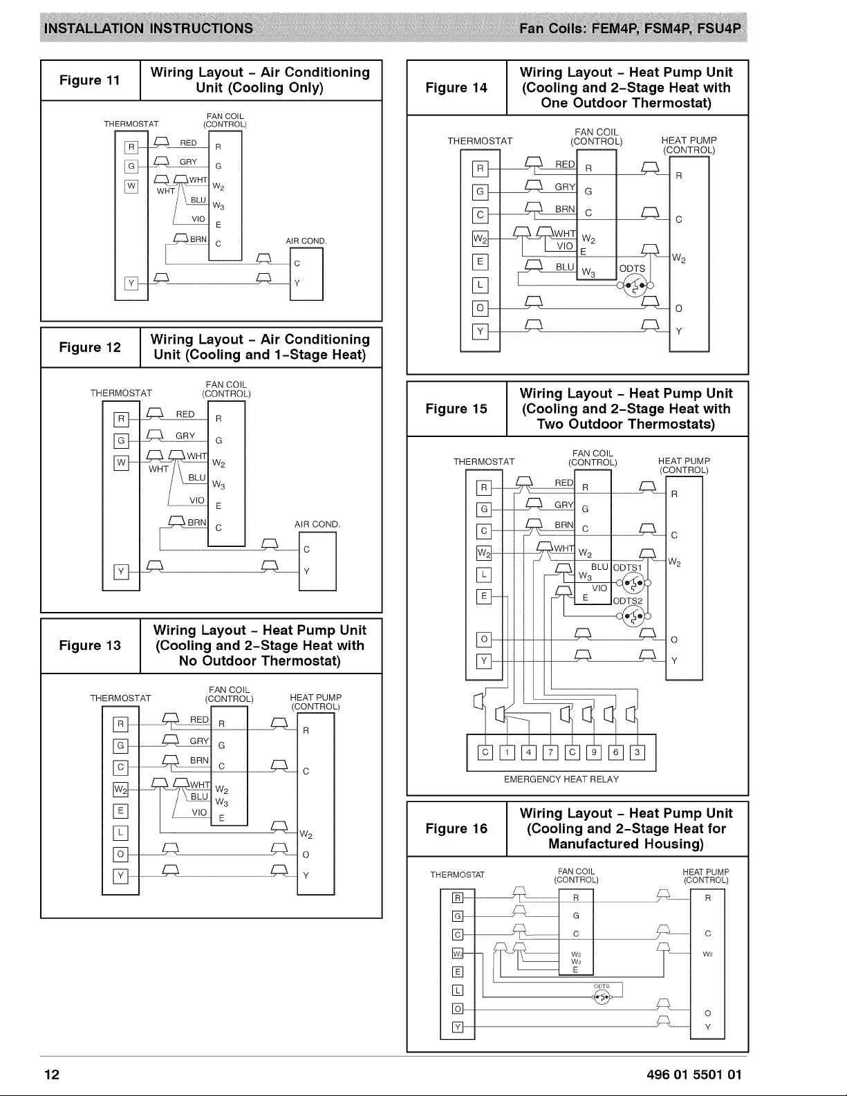
B.
24V
CONTROL
SYSTEM
Connection
to
Unit
Wire
low
voltage
in
accordance
with
wiring
label on
the
blower
(also
refer
to
Figure
11
through
Figure
16).
Use
18
AWG
color-coded,
insulated
(85
°C
minimum)
wire
to
make
the
low-voltage connections
between
the
thermostat,
the
unit,
and
the
outdoor
equipment.
If
the
thermostat
is
located
more
than
100
feet
from
the
unit
(as
measured
along
the
low
voltage
wire),
use
16
AWG
color-coded,
insulated
(35
°C
minimum)
wire.
All
wiring
must
be
NEC
Class
1
and
must
be
separated
from
incoming
power
leads.
Refer
to
outdoor
unit
wiring
instructions
for
additional
wiring
recommendations.
Heater
Staging
The
controls
are
factory
circuited
for
single-stage
operation
(refer
to
Figure
12).
When
2
stages
are
desired,
cut
W3
at
the
W2
wire
nut,
strip,
and
reconnect
according
to
the
thermostat
kit
instruction
(refer
to
Figure
14
-
outdoor
thermostat
optional).
When
3
stages
are
desired,
cut
the
W2
wire
nut
off
and
discard.
Strip
W2,
WS,
and
E,
and
reconnect
according
to
the
thermostat
kit
instructions
(refer
to
Figure
15
outdoor
thermostats
optional).
A
CAUTION
UNIT
OPERATION
HAZARD
Failure
to
follow
this
caution
may
result
in
improper
product
operation.
If
W2,
W3,
and
E
on
any
3
stage
heater
(18,
20, 24,
or
30kW)
are
individually
connected
-
as
with
outdoor
thermostats
or
any
other
situation
-
emergency
heat
relay
must
be
used.
If
relay
is
not
used,
blower
may
not
operate
when
heaters
are
energized.
Manufactured
Housing
In
manufactured
housing
applications,
the
Code
of
Federal
Regulations,
Title
24,
Chapter
XX,
Part
3280.714
requires
that
supplemental
electric
heat
be
locked
out
at
outdoor
temperatures
above
40°F
(4°C),
except
for
a
heat
pump
defrost
cycle.
Refer
to
Figure
16
for
typical
low
voltage
wiring
with
outdoor
thermostat.
496
01
5501
01
11
:
Wiring
Layout
-
Air
Conditioning
Figure
11
: :
Unit
(Cooling
Only)
FAN
COIL
THERMOSTAT
(CONTROL)
rR
RED
|
GRY
G
WHT
W
WHT
2
BLU
We
vio
E
BRN
c
AIR
COND.
a
Ht
es
PHA
y
:
Wiring
Layout
-
Air
Conditioning
Figure
12
Unit
(Cooling
and
1-Stage
Heat)
FAN
COIL
THERMOSTAT
(CONTROL)
R
G
Ww
AIR
COND.
Wiring
Layout
-
Heat
Pump
Unit
Figure
14
(Cooling
and
2-Stage
Heat
with
One
Outdoor
Thermostat)
FAN
COIL
THERMOSTAT
(CONTROL)
HEAT
PUMP
(CONTROL)
R R
R
G
Wiring
Layout
-
Heat
Pump
Unit
Figure
13
(Cooling
and
2-Stage
Heat
with
No
Outdoor
Thermostat)
FAN
COIL
THERMOSTAT
(CONTROL)
HEAT
PUMP
(CONTROL)
R
RED]
a
R
G
GRY
G
BRN
Cc
We
Ws
E
Wiring
Layout
-
Heat
Pump
Unit
Figure
15
(Cooling
and
2-Stage
Heat
with
Two
Outdoor
Thermostats)
FAN
COIL
THERMOSTAT
(CONTROL)
HEAT
PUMP
(CONTROL)
R R
R
G G
C
Woe
W.
E
1
4
7/|C}]9
6
3
EMERGENCY
HEAT
RELAY
Wiring
Layout
-
Heat
Pump
Unit
Figure
16
(Cooling
and
2-Stage
Heat
for
Manufactured
Housing)
THERMOSTAT
FAN
COIL
HEAT
PUMP
(CONTROL) (CONTROL)
R
12
496
01
5501
01
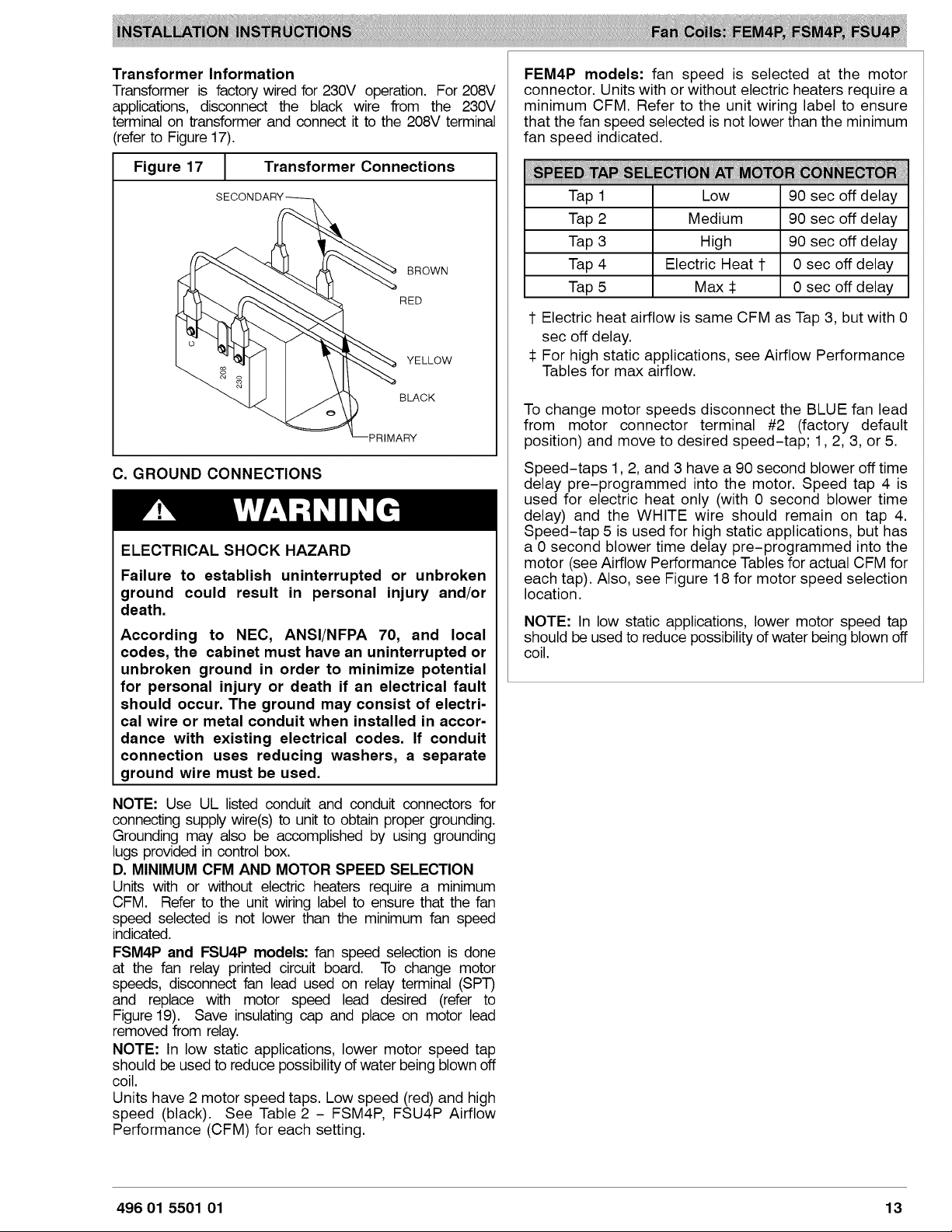
Transformer
Information
Transformer
is
factory
wired
for
230V
operation.
For
208V
applications,
disconnect
the
black
wire
from
the
230V
terminal
on
transformer
and
connect
it
to
the
208V
terminal
(refer
to
Figure
17).
Transformer
Connections
Figure
17
C.
GROUND
CONNECTIONS
7
aN
Le
ELECTRICAL
SHOCK
HAZARD
Failure
to
establish
uninterrupted
or
unbroken
ground
could
result
in
personal
injury
and/or
death.
According
to
NEC,
ANSI/NFPA
70,
and
local
codes,
the
cabinet
must
have
an
uninterrupted
or
unbroken
ground
in
order
to
minimize
potential
for
personal
injury
or
death
if
an
electrical
fault
should
occur.
The
ground
may
consist
of
electri-
cal
wire
or
metal
conduit
when
installed
in
accor-
dance
with
existing
electrical
codes.
If
conduit
connection
uses
reducing
washers,
a
separate
ground
wire
must
be
used.
NOTE:
Use
UL
listed
conduit
and
conduit
connectors
for
connecting
supply
wire(s)
to
unit
to
obtain
proper
grounding.
Grounding
may
also
be
accomplished
by
using
grounding
lugs
provided
in
control
box.
D.
MINIMUM
CFM
AND
MOTOR
SPEED
SELECTION
Units
with
or
without
electric
heaters
require
a
minimum
CFM.
Refer
to
the
unit
wiring
label
to
ensure
that
the
fan
speed
selected
is
not
lower
than
the
minimum
fan
speed
indicated.
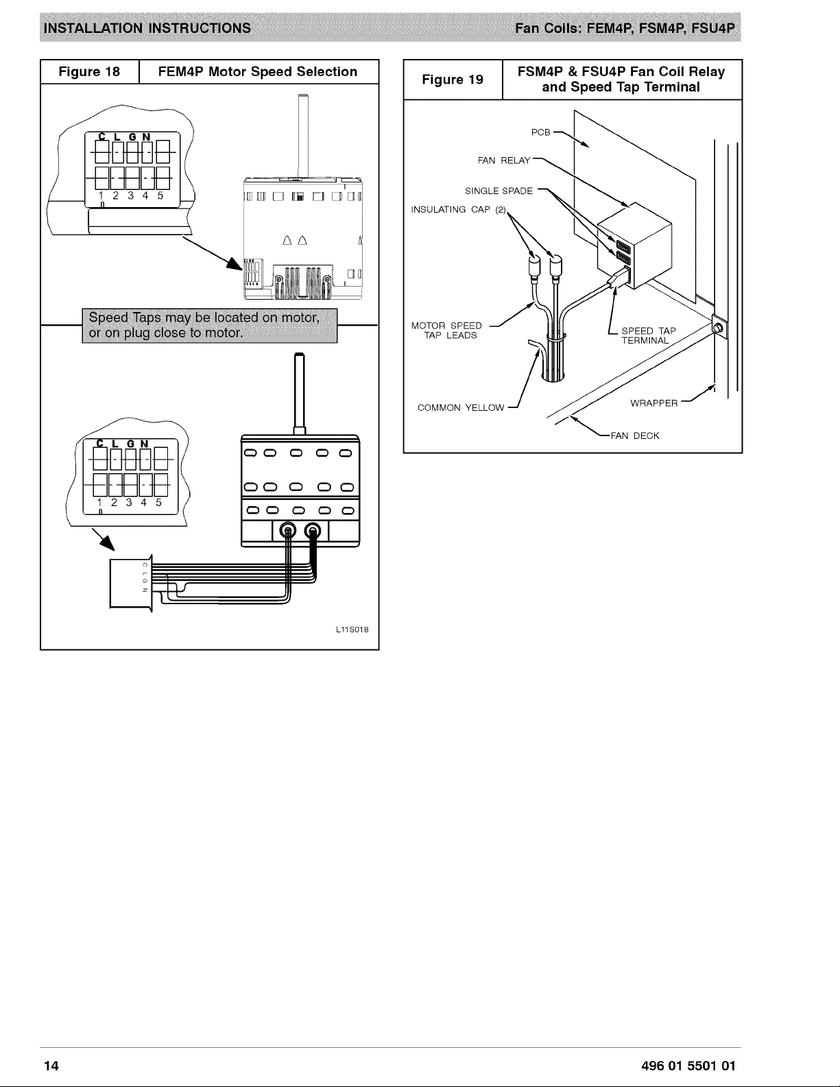
FSM4P
and
FSU4P
models:
fan
speed
selection
is
done
at
the
fan
relay
printed
circuit
board.
To
change
motor
speeds,
disconnect
fan
lead
used
on relay
terminal
(SPT)
and
replace
with
motor
speed
lead
desired
(refer
to
Figure
19).
Save
insulating
cap
and
place
on
motor
lead
removed
from
relay.
NOTE:
In
low
static
applications,
lower
motor
speed
tap
should
be
used
to
reduce
possibility
of
water
being
blown
off
coil.
Units
have
2
motor
speed
taps.
Low
speed
(red)
and
high
speed
(black).
See
Table
2 -
FSM4P,
FSU4P
Airflow
Performance
(CFM)
for
each
setting.
FEM4P
models:
fan
speed
is
selected
at
the
motor
connector.
Units
with
or
without
electric
heaters
require
a
minimum
CFM.
Refer
to
the
unit
wiring
label
to
ensure
that
the fan
speed
selected
is
not
lower
than
the
minimum
fan
speed
indicated.
ONN
|
90
sec
off
delay
Tap
1
Low
Tap
2
Medium
90
sec
off
delay
Tap
3
High
90
sec
off
delay
Tap
4
Electric
Heat
tT
|
O
sec
off
delay
Tap
5
Max
+
0
sec
off
delay
T
Electric
heat
airflow
is
same
CFM
as
Tap
3,
but
with
0
sec
off
delay.
+
For
high
static
applications,
see
Airflow
Performance
Tables
for
max
airflow.
To
change
motor
speeds
disconnect
the
BLUE
fan
lead
from
motor
connector
terminal
#2
(factory
default
position)
and
move
to
desired
speed-tap;
1,
2,
3,
or
5.
Speed-taps
1,
2,
and
3
have
a
90
second
blower
off
time
delay
pre-programmed
into
the
motor.
Speed
tap
4
is
used
for
electric
heat
only
(with
O
second
blower
time
delay)
and
the
WHITE
wire
should
remain
on
tap
4.
Speed-tap
5
is
used
for
high
static
applications,
but
has
a
0
second
blower
time
delay
pre-programmed
into
the
motor
(see
Airflow
Performance
Tables
for
actual
CFM
for
each
tap).
Also,
see
Figure
18
for
motor
speed
selection
location.
NOTE:
In
low
static
applications,
lower
motor
speed
tap
should
be
used
to
reduce
possibility
of
water
being
blown
off
coil.
496
01
5501
01
13
Figure
18
FEM4P
Motor
Speed
Selection
T
WU
GwOOO!
L11S018
Figure
19
FSM4P
&
FSU4P
Fan
Coil
Relay
g
and
Speed
Tap
Terminal
FAN
RELAY
SINGLE
SPADE
\\
MOTOR
SPEED
a
TAP
LEADS
INSULATING
CAP
(2)
COMMON
YELLOW
PCB
.
SPEED
TAP
TERMINAL
_*
WRAPPER
oN
FAN
DECK
14
496
01
5501
01
REFRIGERANT
TUBING
Refrigerant
Tubing
Connection
and
Evacuation
Use
accessory
tubing
package
or
field-supplied
tubing
of
refrigerant
grade.
Suction
tube
must
be
insulated.
Do
not
use
damaged,
dirty,
or
contaminated
tubing
because
it
may
plug
refrigerant
flow-control
device.
ALWAYS
evacuate
the
coil
and
field-supplied
tubing
to
500
microns
before
opening
outdoor
unit
service
valves.
4&
CAUTION
PRODUCT
DAMAGE
HAZARD
Failure
to
follow
this
caution
may
result
in
product
or
property
damage.
A
brazing
shield
MUST
be
used
when
tubing
sets
are
being
brazed
to
the
unit
connections
to
prevent
damage
to
the
unit
surface and
condensate
pan
fitting
caps.
Units
have
sweat
suction
and
liquid
tube
connections.
Make
suction
tube
connection
first.
1.
Cut
tubing
to
correct
length.
2.
Insert
tube
into
sweat
connection
on
unit
until
it
bottoms.
3.
Braze
connection
using
silver
bearing
or
non-silver
bearing
brazing
materials.
Do
not
use
solder
(materials
which
melt
below
800°F
/
427°C).
Consult
local
code
requirements.
4.
Evacuate
coil
and
tubing
system
to
500
microns
using
deep
vacuum
method.
4&
CAUTION
PRODUCT
DAMAGE
HAZARD
Failure
to
follow
this
caution
may
result
in
product
or
property
damage.
Wrap
a
wet
cloth
around
rear
of
fitting
to
prevent
damage
to
piston
assembly
or
TXV
and
factory-made
joints.
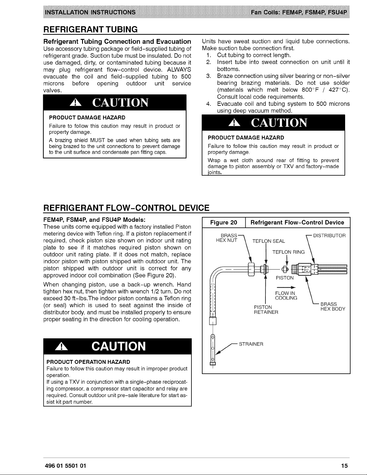
REFRIGERANT
FLOW-CONTROL
DEVICE
FEM4P,
FSM4P,
and
FSU4P
Models:
These
units
come
equipped
with
a
factory
installed
Piston
metering
device
with
Teflon
ring.
If
a
piston
replacement
if
required,
check
piston
size
shown
on
indoor
unit
rating
plate
to
see
if it
matches
required
piston
shown
on
outdoor
unit
rating
plate.
If
it
does
not
match,
replace
indoor
piston
with
piston
shipped
with
outdoor
unit.
The
piston
shipped
with
outdoor
unit
is
correct
for
any
approved
indoor
coil
combination
(See
Figure
20).
When
changing
piston,
use
a
back-up
wrench.
Hand
tighten
hex
nut,
then
tighten
with
wrench
1/2
turn.
Do
not
exceed
30
ft-lbs.The
indoor
piston
contains
a
Teflon
ring
(or
seal)
which
is
used
to
seat
against
the
inside
of
distributor
body,
and
must
be
installed
properly
to
ensure
proper
seating
in
the
direction
for
cooling
operation.
A
CAUTION
PRODUCT
OPERATION
HAZARD
Failure
to
follow
this
caution
may
result
in
improper
product
operation.
If
using
a
TXV
in
conjunction
with
a
single-phase
reciprocat-
ing
compressor,
a
compressor
start
capacitor
and
relay
are
required.
Consult outdoor
unit
pre-sale
literature
for
start
as-
sist
kit
part
number.
Figure
20
Refrigerant
Flow-Control
Device
BRASS
HEX NUT
DISTRIBUTOR
TEFLON
SEAL
TEFLON
RING
&
Elana
fe\/-=4
PISTON
ence
FLOW
IN
COOLING
BRASS
HEX
BODY
PISTON
RETAINER
aa
STRAINER
Ci
496
01
5501
01
15
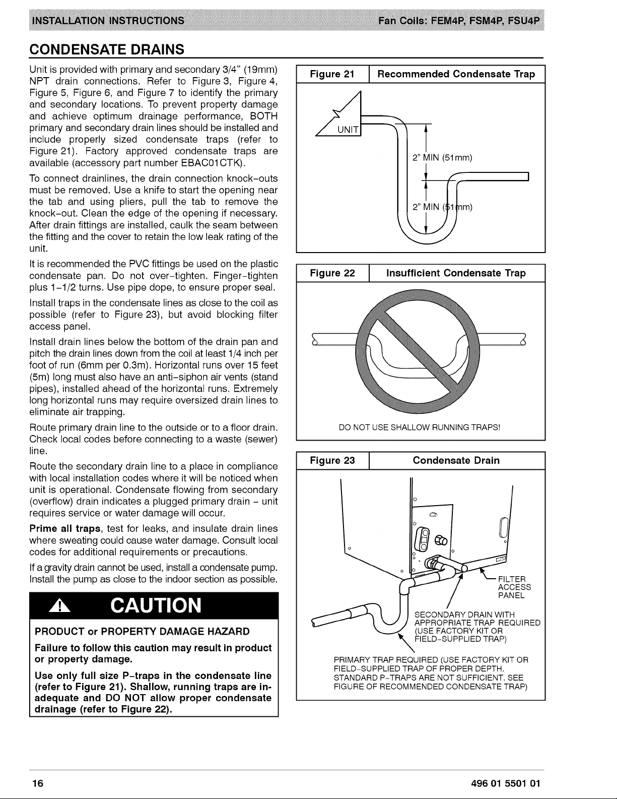
CONDENSATE
DRAINS
Unit
is
provided
with
primary
and
secondary
3/4”
(19mm)
NPT
drain
connections.
Refer
to
Figure
3,
Figure
4,
Figure
5,
Figure
6,
and
Figure
7
to
identify
the
primary
and
secondary
locations.
To
prevent
property
damage
and
achieve
optimum
drainage
performance,
BOTH
primary
and
secondary
drain
lines
should
be
installed
and
include
properly
sized
condensate
traps
(refer
to
Figure
21).
Factory
approved
condensate
traps
are
available
(accessory
part
number
EBACO1CTK).
To
connect
drainlines,
the
drain
connection
knock-outs
must
be
removed.
Use
a
knife
to
start
the
opening
near
the
tab
and
using
pliers,
pull
the tab
to
remove
the
knock-out.
Clean
the
edge
of
the
opening
if
necessary.
After drain
fittings
are
installed,
caulk
the
seam
between
the
fitting
and
the
cover
to
retain
the
low
leak
rating
of
the
unit.
It
is
recommended
the
PVC
fittings
be
used
on
the
plastic
condensate
pan.
Do
not
over-tighten.
Finger-tighten
plus
1-1/2
turns.
Use
pipe
dope,
to
ensure
proper
seal.
Install
traps
in
the
condensate
lines
as
close
to
the
coil
as
possible
(refer
to
Figure
23),
but
avoid
blocking
filter
access
panel.
Install
drain
lines
below
the
bottom
of
the
drain
pan
and
pitch
the
drain
lines
down
from
the
coil
at
least
1/4
inch
per
foot
of
run
(6mm
per
0.3m).
Horizontal
runs
over
15
feet
(5m)
long
must
also
have
an
anti-siphon
air
vents
(stand
pipes),
installed
ahead
of
the
horizontal
runs.
Extremely
long
horizontal
runs
may
require
oversized
drain
lines
to
eliminate
air
trapping.
Route
primary
drain
line
to
the
outside
or
to
a
floor
drain.
Check
local
codes
before
connecting
to
a
waste
(Sewer)
line.
Route
the
secondary
drain
line
to
a
place
in
compliance
with
local
installation
codes
where
it
will
be
noticed
when
unit
is
operational.
Condensate
flowing
from
secondary
(overflow)
drain
indicates
a
plugged
primary
drain
-
unit
requires
service
or
water
damage
will
occur.
Prime
all
traps,
test
for
leaks,
and
insulate
drain
lines
where
sweating
could
cause
water
damage.
Consult
local
codes
for
additional
requirements
or
precautions.
If
a
gravity
drain
cannot
be
used,
install
a
condensate
pump.
Install
the
pump
as
close
to
the
indoor
section
as
possible.
A
CAUTION
PRODUCT
or
PROPERTY
DAMAGE
HAZARD
Failure
to
follow
this
caution
may
result
in
product
or
property
damage.
Use
only
full
size
P-traps
in
the
condensate
line
(refer
to
Figure
21).
Shallow,
running
traps
are
in-
adequate
and
DO
NOT
allow
proper
condensate
drainage
(refer
to
Figure
22).
Figure
21
Recommended
Condensate
Trap
UNIT
2”
MIN
(51mm)
2”
MIN
(
Figure
22
Insufficient
Condensate
Trap
DO
NOT
USE
SHALLOW
RUNNING
TRAPS!
Figure
23
Condensate
Drain
FILTER
ACCESS
PANEL
SECONDARY
DRAIN
WITH
APPROPRIATE
TRAP
REQUIRED
(USE
FACTORY
KIT
OR
\
FELD-SUPPLIED
TRAP)
PRIMARY
TRAP
REQUIRED
(USE
FACTORY
KIT
OR
FIELD-SUPPLIED
TRAP
OF
PROPER
DEPTH.
STANDARD
P-TRAPS
ARE
NOT
SUFFICIENT.
SEE
FIGURE
OF
RECOMMENDED
CONDENSATE
TRAP)
16
496
01
5501
01
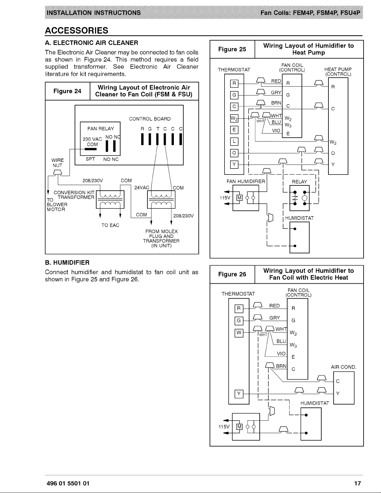
ACCESSORIES
A.
ELECTRONIC
AIR
CLEANER
The
Electronic
Air
Cleaner
may
be
connected
to
fan
coils
as
shown
in
Figure
24.
This
method
requires
a
field
supplied
transformer.
See
Electronic
Air
Cleaner
literature
for
kit
requirements.
Fiqure
24
Wiring
Layout
of
Electronic
Air
g
Cleaner
to
Fan
Coil
(FSM
&
FSU)
CONTROL
BOARD
FAN
RELAY
RGTccc
230
vac
NO
NG
| | |
|
COM
a
WIRE
SPT
NO
NC
208/230V
COM
24VAC
COM
CONVERSION
KIT
To
TRANSFORMER
Load
Lod
BLOWER
BLOWE!
(vr)
aaas
’
'
COM
poses
TO
EAC
'
FROM
MOLEX
PLUG
AND
TRANSFORMER
(IN
UNIT)
B.
HUMIDIFIER
Connect
humidifier
and
humidistat
to
fan
coil
unit
as
shown
in
Figure
25
and
Figure
26.
:
Wiring
Layout
of
Humidifier
to
Figure
25
Heat
Pump
FAN
COIL
THERMOSTAT
(CONTROL)
HEAT
PUMP
FAN
HUMIDIFIER
—_
—_
115V
R
G
(CONTROL)
RED]
5
R
GRY|
BRN
uu
|
|
HUMIDISTAT
Lt,
Fiqure
26
Wiring
Layout
of
Humidifier
to
g
Fan
Coil
with
Electric
Heat
THERMOSTAT
(CONTROL)
FI
L\
RED
|,
[5]
LA\
ary
|,
[<]
f
115V
f
Lgl
|
|
W3
|
l
E
|
BRN!
4
AIR
COND.
| |
|
|
c
||
L\
LAY
Pt
|
|
HUMIDISTAT
pb
Lp
oof
al,
496
01
5501
01
17

SEQUENCE
OF
OPERATIONS
A.
CONTINUOUS
FAN
Thermostat
closes
R
to
G.
G
energizes
fan
relay on
PCB
(FSM4P,
FSU4P)
or
sends
signal
direct
to
motor
(FEM4P),
which
completes
circuit
to
indoor
blower
motor.
When
G
is
de-energized,
there
is
a
90
second
off
delay
before
relay
opens.
B.
COOLING
MODE
Thermostat
energizes
R
to
G, R
to
Y,
and
R
to
O (heat
pump
only).
G
energizes
fan
relay
on
PCB
(FSM4P,
FSU4P)
or
sends
signal
direct
to
motor
(FEM4P),
which
completes
circuit
to
indoor
blower
motor.
When
G
is
de-energized,
there
is
a
90
second
off
delay
before
fan
relay
opens.
C.
HEAT
PUMP
HEATING
MODE
Thermostat
energizes
R
to
G
and
R
to Y.
G
energizes
fan
relay on
PCB
(FSM4P,
FSU4P)
or
sends
signal
direct
to
motor
(FEM4P),
which
completes
circuit
to
indoor
blower
START-UP
PROCEDURE
motor.
When
G
is
de-energized,
there
is
a
90
second
off
delay
before
fan
relay
opens.
D.
HEAT
PUMP
HEATING
WITH
AUXILIARY
ELECTRIC
HEAT
Thermostat
energizes
R
to
G,
R
to
Y,
and
RtoW.
G
energizes
fan
relay
on
PCB
which
completes
circuit
to
indoor
blower
motor.
W
energizes
electric
heat
relay(s)
which
completes
circuit
to
heater
element(s).
When
W
is
de-energized,
electric
heat
relay(s)
open,
turning
off
heater
elements.
When
G
is
de-energized
there
is
a
90
second
off
delay
before
fan
relay
opens.
E.
ELECTRIC
HEAT
OR
EMERGENCY
HEAT
MODE
Thermostat
closes
R
to
W.
W
energizes
electric
heat
relay(s)
which
completes
circuit
to
heater
element(s).
Blower
motor
is
energized
through
normally
closed
contacts
on
fan
relay.
When
W
is
de-energized,
electric
heat
relay(s)
opens.
Refer
to
outdoor
unit
Installation
Instructions
for
system
start-up
instructions
and
refrigerant
charging
method
details.
CARE
AND
MAINTENANCE
The
system
should
be
regularly
inspected
by
a
qualified
service technician.
Consult
the
servicing
dealer
for
recommended
frequency.
Between
visits,
the
only
consumer
service
recommended
or
required
is
air
filter
maintenance
and
condensate
drain
operation.
Air
Filter
Inspect
air
filters
at
least
monthly
and
replace
or
clean
as
required.
Disposable
type
filters
should
be
replaced.
Reusable
type
filters
may
be
cleaned
by
soaking
in
mild
detergent
and
rinsing
with
cold
water.
Install
filters
with
the
arrows
on
the
side
pointing
in
the
direction
of
air
flow.
Condensate
Drain
During
the
cooling
season
check
at
least
monthly
for
free
flow
of
drainage
and
clean
if
necessary.
A
CAUTION
PRODUCT
DAMAGE
HAZARD
Failure
to
follow
this
caution
may
result
in
poor
unit
performance
and/or
product
damage.
Never
operate
unit
without
a
filter.
Factory
autho-
rized
filter
kits
must
be
used
when
locating
the
fil-
ter
inside
the
unit.
For
those
applications
where
access
to
an
internal
filter
is
impractical,
a
field-
supplied
filter
must
be
installed
in
the
return
duct
system.
18
496
01
5501
01
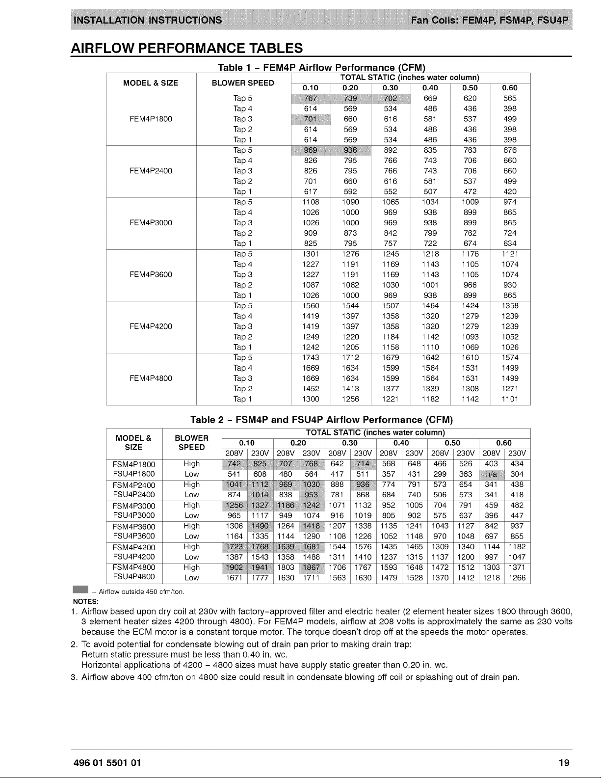
AIRFLOW
PERFORMANCE
TABLES
Table
1
-
FEM4P
Airflow
Performance
(CFM)
TOTAL
STATIC
(inches water
column)
MODEL
&
SIZE
BLOWER
SPEED
0.40
050
0.60
Tap
5
669 620 565
Tap
4
534
486 436
398
FEM4P1800
Tap
3
616
581
537 499
Tap
2
614
569
534
486
436 398
Tap
1
614
569
534
486
436 398
Tap
5
892 835 763
676
Tap
4
826
795
766 743
706
660
FEM4P2400
Tap
3
826
795 766
743
706
660
Tap
2
701
660
616
581
537 499
Tap
1
617
592
552 507 472 420
Tap
5
1108 1090 1065 1034 1009
974
Tap
4
1026
1000
969 938 899 865
FEM4P3000
Tap
3
1026 1000
969 938 899 865
Tap
2
909 873 842
799
762 724
Tap
1
825
795
757 722 674 634
Tap
5
1301
1276 1245 1218 1176
1121
Tap
4
1227
1191
1169 1143 1105 1074
FEM4P3600
Tap
3
1227
1191
1169 1143 1105 1074
Tap
2
1087
1062
1030
1001
966 930
Tap
1
1026
1000
969 938 899 865
Tap
5
1560 1544 1507 1464 1424 1358
Tap
4
1419 1397 1358 1320 1279 1239
FEM4P4200
Tap
3
1419 1397 1358 1320 1279 1239
Tap
2
1249 1220 1184 1142 1093 1052
Tap
1
1242 1205 1158 1110 1069 1026
Tap
5
1743 1712 1679 1642 1610 1574
Tap
4
1669 1634 1599 1564
1531
1499
FEM4P4800
Tap
3
1669 1634 1599 1564
1531
1499
Tap
2
1452 1413 1377 1339 1308
1271
Tap
1
1300 1256
1221
1182 1142
1101
Table
2
-
FSM4P
and
FSU4P
Airflow
Performance
(CFM)
TOTAL
STATIC
(inches water
column)
Mee
&
PRED
0.10
0.20 0.30 0.40 0.50 0.60
208V
|
230V
|
208V
|
230V
|
208V
|
230V
|
208V
|
230V
|
208V
|
230V
|
208V
|
230V
FSM4P1800
High
568
|
648
|
466
|
526
|
403
|
434
FSU4P1800
Low
357
|
431
|
299
|
363
|
A/a)
304
FSM4P2400
High
774
|
791
573
|
654
|
341
438
FSU4P2400
Low
868
|
684
|
740
|
506
|
573
|
341
|
418
FSM4P3000
High
1132
|
952
|
1005
|
704
|
791
|
459
|
482
FSU4P3000
Low
1019
|
805
|
902
|
575
|
637
|
396
|
447
FSM4P3600
High
1338
|
1135
|
1241
|
1043
|
1127
|
842
|
937
FSU4P3600
Low
1226
|
1052
|
1148
|
970
|
1048
|
697
|
855
FSM4P4200
High
1576
|
1435
|
1465
|
1309
|
1340
|
1144
|
1182
FSU4P4200
Low
1410
|
1237
|
1315
|
1137
|
1200
|
997
|
1047
FSM4P4800
High
1767
|
1593
|
1648
|
1472
|
1512
|
1303
|
1371
FSU4P4800
Low
1630
|
1479
|
1528
|
1370
|
1412
|
1218
|
1266
12)
—
airflow
outside
450
cfm/ton.
NOTES:
1.
Airflow
based
upon
dry
coil
at
230v
with
factory-approved
filter
and
electric
heater
(2
element
heater
sizes
1800
through
3600,
3
element
heater
sizes
4200
through
4800).
For
FEM4P
models,
airflow
at
208
volts
is
approximately
the
same
as
230
voits
because
the
ECM
motor
is
a
constant
torque
motor.
The
torque
doesn’t
drop
off
at
the
speeds
the
motor
operates.
2.
To
avoid
potential
for
condensate
blowing
out
of
drain
pan
prior
to
making
drain
trap:
Return
static
pressure
must
be
less
than 0.40
in.
we.
Horizontal
applications
of
4200
-
4800
sizes
must
have
supply
static
greater
than
0.20
in.
we.
8.
Airflow
above
400 cfm/ton
on
4800
size
could
result
in
condensate
blowing
off
coil
or
splashing
out
of
drain
pan.
496
01
5501
01
19
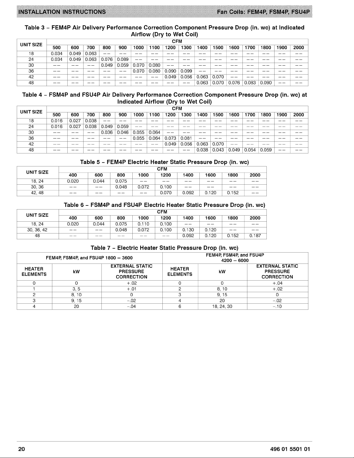
Table
3
-
FEM4P
Air
Delivery
Performance
Correction
Component
Pressure
Drop
(in.
we)
at
Indicated
Airflow
(Dry
to
Wet
Coil)
NIT
SIZE
CFM
UNIT'S
500
|
600
|
700
|
800
|
900
|
1000
|
1100
|
1200
|
1300
|
1400
|
1500
|
1600
|
1700
|
1800
|
1900
|
2000
18
0.034
|
0.049
/0.063
|
——
|
——
|
——
|
——
|
-=
[|
-=
|
-=
7
==
|
== P= f=
24
0.034
|
0.049
|
0.063
|
0.076
[0.089
|
——
|
——
|
——
|
——
|
——
|
-=
|
-=
|
-= f=
30
——
|
—=
|
==
[0.049
|
0.059
[0.070 |0.080
|
——
|
——
|
——
|
-=
|
==
|
-=
|
== ==
36
==
|
==
|
==
|
==
|
==
|0.070
|
0.080
|0.090
|
0.099
|
——
|
——
|
——
|
-—
|
-=
|
==
42
==)
== ==
f
==
|
==
|
==
|
==
[0.049
|
0.056
[0.063
|
0.070
|
——
|
——
|
——
|
-=
7
=
48
==)
=
f=
= =
==
|
==
|
==
[0.063
|
0.070
|
0.076
|
0.083
[0.090
|
——
|
==
Table
4
-
FSM4P
and
FSU4P
Air
Delivery
Performance
Correction
Component
Pressure
Drop
(in.
wc)
at
Indicated
Airflow
(Dry
to
Wet
Coil)
UNIT
SIZE
CFM
500
|
600
|
700
|
800
|
900
|
1000
|
1100
|
1200
|
1300
|
1400
|
1500
|
1600
|
1700
|
1800
|
1900
|
2000
18
0.016
|
0.027
]0.038
|
——
|
——
|
——
|
——
|
——
|
——
|
-—
|
-=
|
==
|
==
|
==
[== |
==
24
0.016
|
0.027
|
0.038
|
0.049
[0.059
|
——
|
——
|
——
|
——
|
——
|
——
|
-=
|
==
|
=-
[==
|
==
30 == ——
|
——
|
0.036
|
0.046
|
0.055
|
0.064
|
——
|
——
|
——
|
——
|
-—
|
——
|
==
|
==
|
==
36 == ——
|
——
|
——
|
——
|
0.055
|
0.064
|
0.073
|
0.081
|
——
|
——
|
——
|
——
|
-—
|
-=
|
==
42
== ——
|
——
|
—=
|
—=
|
—=
|
—=
[0.049]
0.056
|
0.063
|0.070
|
——
|
——
|
——
|
—-—
|
——
48
== ——
|
-—
|
-=
|
—=
|
-=
|
—=
|
—=
|]
—=
|
0.038
|
0.043
|
0.049
|
0.054
|
0.059
|
——
|
——
Table
5
-
FEM4P
Electric
Heater
Static
Pressure
Drop
(in.
wc)
CFM
UNIT
SIZE
400 600 800
1000 1200 1400 1600 1800
2000
18,
24
0.020
0.044
|
0.075
== == == == == ==
30,
36
== ==
0.048
|
0.072
|
0.100
== == == ==
42,
48
== == == ==
0.070
|
0.092
|
0.120
|
0.152
==
Table
6
-
FSM4P
and
FSU4P
Electric
Heater
Static
Pressure
Drop
(in.
we)
CFM
UNIT
SIZE
400 600 800
1000 1200 1400 1600 1800
2000
18,
24
0.020
0.044
|
0.075
|
0.110
|
0.100
== == == ==
30, 36,
42
== ==
0.048
|
0.072
|
0.100
|
0.130
|
0.120
== ==
48
—= —= —= —= —=
0.092
|
0.120
|
0152
|
0.187
Table
7
-
Electric
Heater
Static
Pressure
Drop
(in.
wc)
FEM4P,
FSM4P,
and
FSU4P
FEM4P,
FSM4P,
and
FSU4P
1800
—
3600 4200
—
6000
HEATER
EXTERNAL
STATIC
HEATER
EXTERNAL
STATIC
ELEMENTS
kW
PRESSURE
ELEMENTS
kW
PRESSURE
CORRECTION
CORRECTION
0 0
+.02
0 0
+.04
1
3,5
+.01
2
8,
10
+.02
2
8,
10
0 3
9,
15
0
3
9,
15
~.02
4
20
~.02
4
20
~.04
6
18,
24,
30
~.10
20
496
01
5501
01
R-410A
QUICK
REFERENCE
GUIDE
R-410A
refrigerant
operates
at
50%
-—
70%
higher
pressures
than
R-22.
Be
sure
that
servicing
equipment
and
replacement
components
are
designed
to
operate
with
R-410A.
R-410A
refrigerant
cylinders
are
rose
colored.
Recovery
cylinder
service
pressure
rating
must
be
400
psig,
DOT
4BA400
or
DOT
BW400.
R-410A
systems
should
be
charged
with
liquid
refrigerant.
Use
a
commercial
type
metering
device
in
the
manifold
hose.
Manifold
sets
should
be
750
psig
high-side
and 200
psig
low-side
with
520
psig
low-side
retard.
Use
hoses
with
750
psig
service
pressure
rating.
Leak
detectors
should
be
designed
to
detect
HFC
refrigerant.
R-410A,
as
with
other
HFC
refrigerants,
is
only
compatible
with
POE
oils.
POE
oils
absorb
moisture
rapidly.
Do
not
expose
oil
to
atmosphere.
POE
oils
may
cause
damage
to
certain
plastics
and
roofing
materials.
Vacuum
pumps
will
not
remove
moisture
from
oil.
A
liquid
line
filter-drier
is
required
on
every
unit.
Do
not
use
liquid
line
filter-driers
with
rated
working
pressures
less
than
600
psig.
Do
not
install
a
suction
line
filter-drier
in
liquid
line.
Wrap
all
filter-driers
and service
valves
with
wet
cloth
when
brazing.
Do
not
use
capillary
tube
indoor
coils.
Never
open
system
to
atmosphere
while
it
is
under
a
vacuum.
When
system
must
be
opened
for
service,
break
vacuum
with
dry
nitrogen
and
replace
all
filter—driers.
Do
not
vent
R-410A
into
the
atmosphere.
Observe
all
WARNINGS,
CAUTIONS,
NOTES,
and
bold
text.
International
Comfort
Products,
LLC
496
01
5501
01
Lewisburg,
TN 37091
USA
21