Downflow Base Kit (Instructions) EBP, EBX, EBV, EBW
Unit Disconnect
WARNING: Before beginning any installation or modification, be sure the main electrical disconnect switch is in the
OFF position. Tag side connect switch with suitable warning label. Electrical shock can cause personal injury or
death.
INTRODUCTION
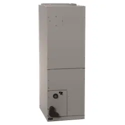
This instruction covers the installation of downflow base kits on models EBP, EBX, EBV and EBW fan coils. (See Table 1.)The
device is designed to provide a means of eliminating open passage through building structure (per UL and NFPA 90B), and
provides a 1-in. clearance between plenum and initial penetration of structure.
DESCRIPTION AND USAGE
The downfiow base kit is required in downflow installations of fan coils. The kit maintains 1-in. minimum clearance between
unit discharge plenum, ductwork, and combustible materials and also provides agap-free seal with the floor. Before installing
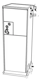
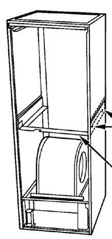
the downflow base, convert the fan-coil unit for downflow installation by positioning unit with filter section at top and rotating
coil 180 degrees. See downflow bracket kit Installation Instructions for details.
INSTALLATION
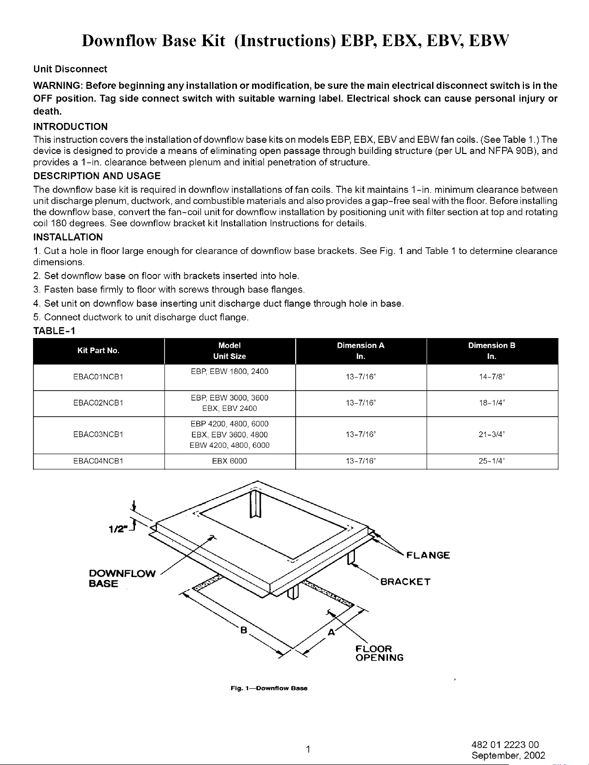
1. Cut a hole in floor large enough for clearance of downflow base brackets. See Fig. 1 and Table 1to determine clearance
dimensions.
2. Set downflow base on floor with brackets inserted into hole.
3. Fasten base firmly to floor with screws through base flanges.
4. Set unit on downflow base inserting unit discharge duct flange through hole in base.
5. Connect ductwork to unit discharge duct flange.
TABLE-1
EBP, EBW 1800, 2400
EBAC01NCB1 13-7/!6" 14-7/8"
EBAC02NCB1 EBP, EBW 3000, 3600 13-7/!6" 18-1/4"
EBX, EBV 2400
EBP 4200, 4800, 6000
EBAC03NCB1 EBX, EBV 3600, 4800 13-7/!6" 21-3/4"
EBW 4200, 4800, 6000
EBAC04NCB1 EBX 6000 13-7/!6" 25-1/4"
"FLANGE
DOWNFLOW
BASE BRACKET
FLOOR
OPENING
Fig. 1--Downflow Base
1 482 01 2223 00
September, 2002