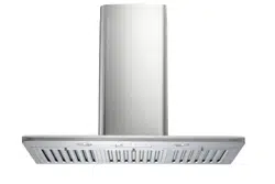
Loading ...
Loading ...
Loading ...
6
4. Secure and tighten the mounting screws.
CAUTION
: MAKE SURE THE HOOD IS
SECURE BEFORE RELEASING.
Ductwork Installation
5. Using Reference E from Table 1 and
measurements on Page 12, mark the leveling
point for duct cover-mounting bracket.
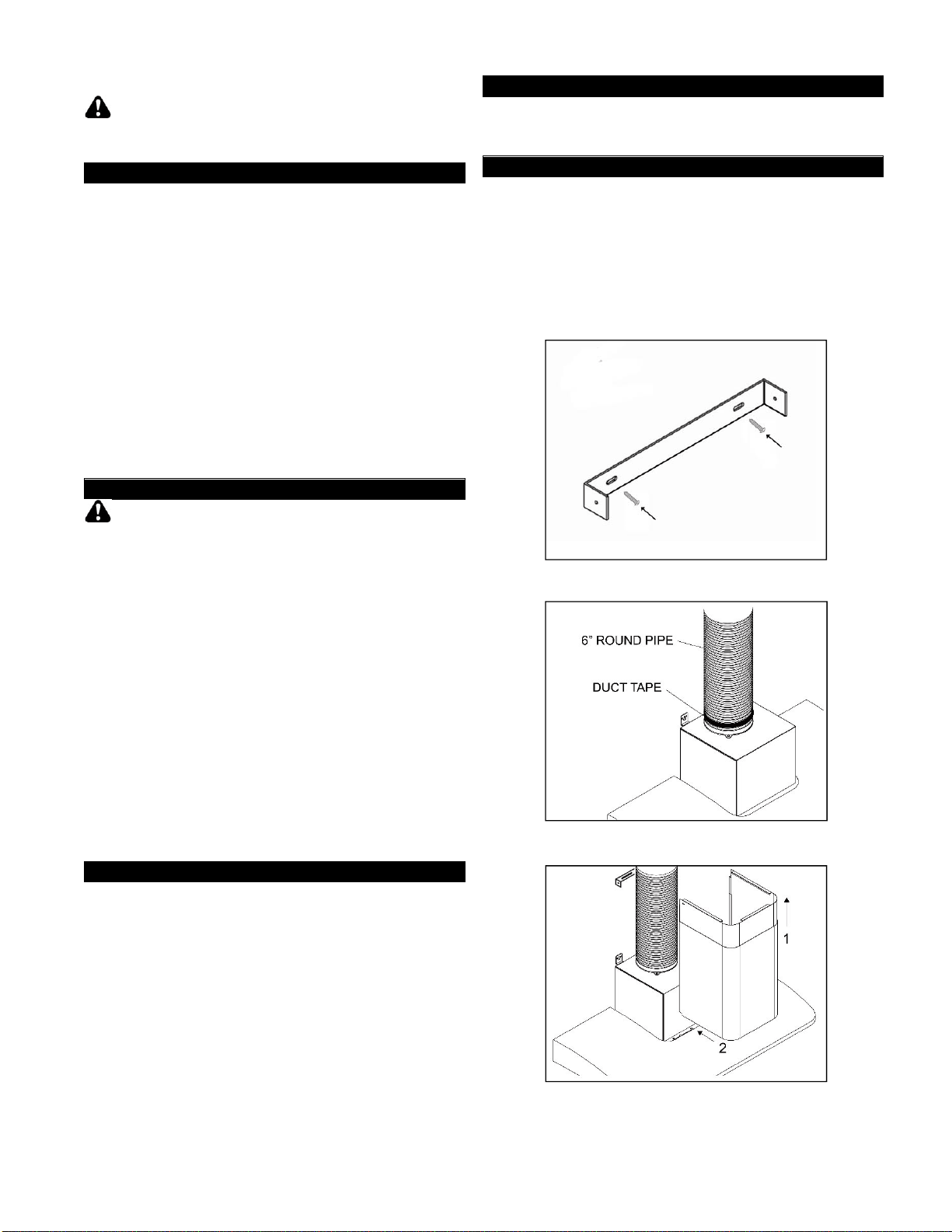
6. Secure the duct cover-mounting bracket to the
wall with two screws (provided). (Figure 5 and
Figure 8) Make sure all screws are tightened.
NOTE: Inner duct cover will cover the duct
cover-mounting bracket.
7. Use 6” steel pipe (not provided) to connect the
plastic exhaust on the hood to the ductwork
above. Use duct tape to ensure all joints are
secure and air tight as shown in Figure 6.
Wiring to Power Supply
THIS RANGE HOOD MUST BE PROPERLY
GROUNDED. MAKE SURE THIS IS DONE BY
QUALIFIED ELECTRICIAN IN ACCORDANCE
WITH ALL APPLICABLE NATIONAL AND
LOCAL ELECTRICAL CODES. BEFORE
CONNECTING WIRES, SWITCH POWER OFF
AT SERVICE PANEL AND LOCK SERVICE
PANEL TO PREVENT POWER FROM BEING
SWITCHED ON ACCIDENTALLY.
8. Connect three wires (black, white and green)
to house wires and cap with wire connectors.
Connect according to color: black to black,
white to white, and green to green.
9. Test the operation of the hood before
performing the next step. Make sure power is
supplied to the hood.
Duct Cover Installation
10. Slide inner duct cover up 2 inches before
sliding entire duct cover onto the hood. (Figure
7)
11. Align the inner duct cover to the duct cover-
mounting bracket. Secure inner duct cover
with two (3/16” x 3/8”) screws (provided).
12. Fasten outer duct cover to plastic plate on the
hood with four (3/16” x 3/8”) screws (provided).
Install / Uninstall Accessories
13. Place baffle filters underneath the hood.
Final Assembly
14. Turn power ON in control panel. Check all lights
and fan operation.
15. Leave this Installation Instructions and Operation
Manual for the homeowner.
Figure 5
Figure 6
Figure 7
Loading ...
Loading ...
Loading ...