
Data Collection Station
User’s Manual
V2.0.0
I
Foreword
General
This manual introduces the functions and operations of the data collection station (hereinafter
referred to as "the Station").
Safety Instructions
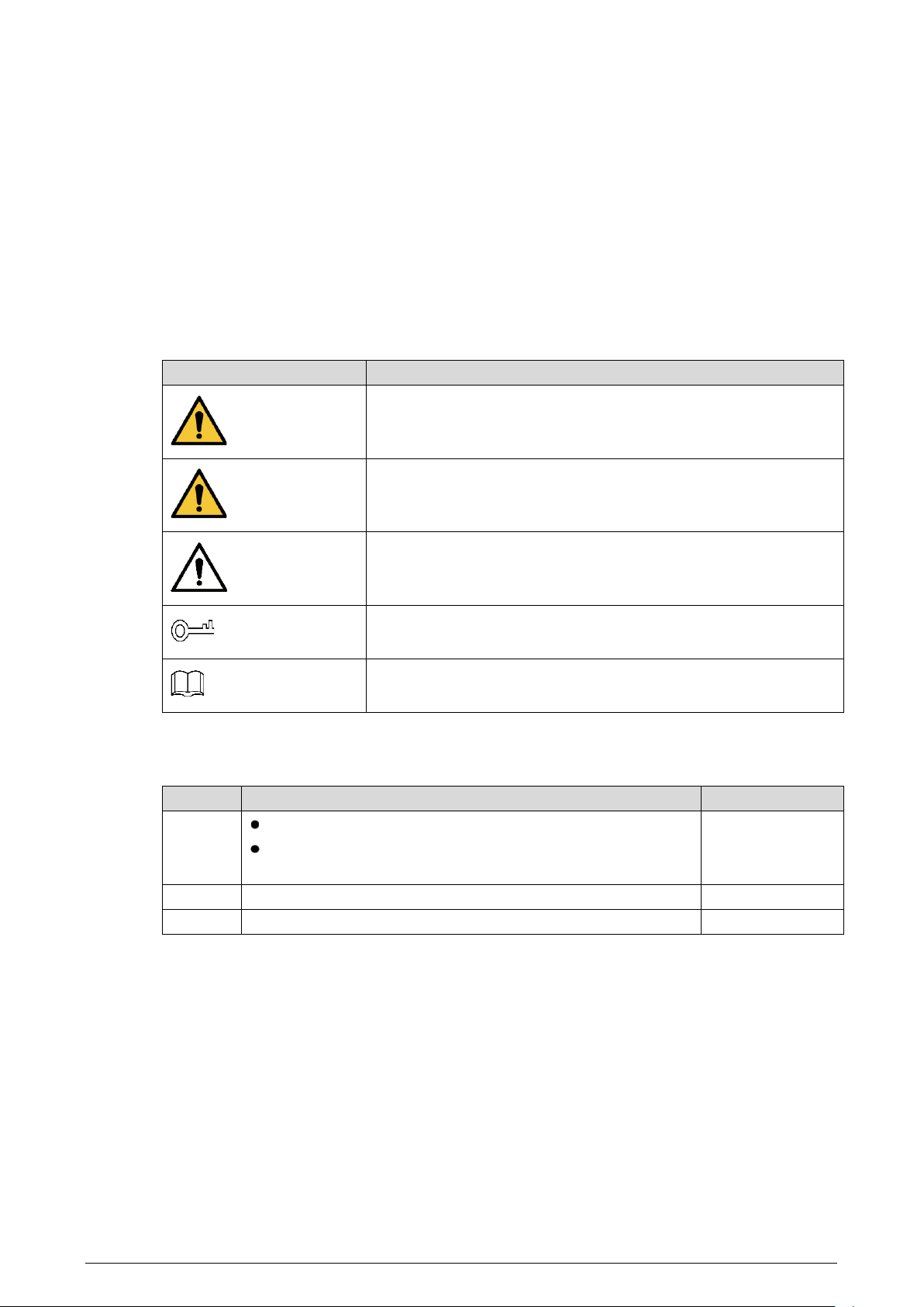
The following signal words might appear in the manual.
Signal Words
Meaning
DANGER
Indicates a high potential hazard which, if not avoided, will result in
death or serious injury.
WARNING
Indicates a medium or low potential hazard which, if not avoided,
could result in slight or moderate injury.
CAUTION
Indicates a potential risk which, if not avoided, could result in
property damage, data loss, reductions in performance, or
unpredictable results.
TIPS
Provides methods to help you solve a problem or save time.
NOTE
Provides additional information as a supplement to the text.
Revision History
Version
Revision Content
Release Time
V2.0.0
Updated figures in "4.1.4 Local Settings".
Added "4.1.5 Platform Configuration" and "4.1.4.6.3 Attack
Defense".
November 2021
V1.0.1
Updated "1.1 Introduction".
May 2021
V1.0.0 First release. March 2021
Privacy Protection Notice
As the device user or data controller, you might collect the personal data of others such as their face,
fingerprints, and license plate number. You need to be in compliance with your local privacy protection
laws and regulations to protect the legitimate rights and interests of other people by implementing
measures which include but are not limited: Providing clear and visible identification to inform people
of the existence of the surveillance area and provide required contact information.

II
About the Manual
The manual is for reference only. Slight differences might be found between the manual and the
product.
We are not liable for losses incurred due to operating the product in ways that are not in
compliance with the manual.
The manual will be updated according to the latest laws and regulations of related jurisdictions.
For detailed information, see the paper user’s manual, use our CD-ROM, scan the QR code or visit
our official website. The manual is for reference only. Slight differences might be found between
the electronic version and the paper version.
All designs and software are subject to change without prior written notice. Product updates
might result in some differences appearing between the actual product and the manual. Please
contact customer service for the latest program and supplementary documentation.
There might be errors in the print or deviations in the description of the functions, operations and
technical data. If there is any doubt or dispute, we reserve the right of final explanation.
Upgrade the reader software or try other mainstream reader software if the manual (in PDF
format) cannot be opened.
All trademarks, registered trademarks and company names in the manual are properties of their
respective owners.
Please visit our website, contact the supplier or customer service if any problems occur while
using the device.
If there is any uncertainty or controversy, we reserve the right of final explanation.

III
Important Safeguards and Warnings
This section introduces content covering the proper handling of the Station, hazard prevention, and
prevention of property damage. Read carefully before using the Station, comply with the guidelines
when using it, and keep the manual safe for future reference.
Operation Requirement
●
Do not place or install the Station in a place exposed to sunlight or near the heat source.
●
Keep the Station away from dampness, dust or soot.
●
Keep the Station installed horizontally on the stable place to prevent it from falling.
●
Do not drop or splash liquid onto the Station, and make sure that there is no object filled with
liquid on the Station to prevent liquid from flowing into the Station.
●
Install the Station in a well-ventilated place, and do not block the ventilation of the Scanner.
●
Operate the Station within the rated range of power input and output.
●
Do not disassemble the Station.
●
Transport, use and store the Station under the allowed humidity and temperature conditions.
Electrical Safety
●
Always replace with the same type of batteries.
●
Use the recommended power cables in the region and conform to the rated power specification.
●
Use the power adapter provided with the Station; otherwise, it might result in people injury and
device damage.
●
The power supply must conform to the requirements of ES1 in IEC 62368-1 standard and be no
higher than PS2. Note that the power supply requirements are subject to the device label.
●
Connect the Station (I-type structure) to the power socket with protective earthing.
●
The appliance coupler is a disconnection device. When using the coupler, keep the angle for easy
operation.

IV
Table of Contents
Foreword ............................................................................................................................................................................ I
Important Safeguards and Warnings ......................................................................................................................... III
1 Overview ....................................................................................................................................................................... 1
Introduction ................................................................................................................................................................................. 1
Features ......................................................................................................................................................................................... 1
Product Appearance ................................................................................................................................................................. 2
1.3.1 Control Module .............................................................................................................................................................. 2
1.3.2 Appearance of Data Collection Modules ............................................................................................................. 4
Description of Buttons ............................................................................................................................................................. 5
Power On ....................................................................................................................................................................................... 6
2 Device Connection ...................................................................................................................................................... 7
Connecting Control Module and Data Collection Module ......................................................................................... 7
Connecting Body Camera and Data Collection Module ............................................................................................. 7
3 HDD Installation .........................................................................................................................................................11
4 Configuration and Operation ..................................................................................................................................14
General ......................................................................................................................................................................................... 14
4.1.1 Login ................................................................................................................................................................................ 15
4.1.2 File Management ........................................................................................................................................................ 16
4.1.3 Searching for Logs ...................................................................................................................................................... 17
4.1.4 Local Settings ............................................................................................................................................................... 19
4.1.5 Platform Configuration ............................................................................................................................................. 53
Web Configuration .................................................................................................................................................................. 56
4.2.1 Login ................................................................................................................................................................................ 56
4.2.2 File Management ........................................................................................................................................................ 57
4.2.3 Configuring Web ......................................................................................................................................................... 58
RAID ...........................................................................................................................................................59
Cybersecurity Recommendations .......................................................................................................61

1
1 Overview
Introduction
Working with body camera, the Station can acquire the data of body cameras and charge them. The
Station can auto recognize and connect the connected body camera through the USB port. Working
with the platform, the Station can authorize the body camera, and auto acquire the electronic
evidence (video, audio, and snapshot). The Station contains control module and data collection
module. One control module can support 4 data collection modules at most.
Features
Recharge and collect data from maximum 32 body cameras at the same time.
Automatically or manually update body cameras.
Automatically create archive and then save the collected electronic data.
Automatically upload the evidence to FTP or the platform.
Automatically synchronize time with the platform.
When there are more than one data collection modules, the Station will collect data from the
body camera in the fixed docks of each data collection module in priority.
You can search, edit, transcode, play back, view, delete and manage all the data in the Station.
2
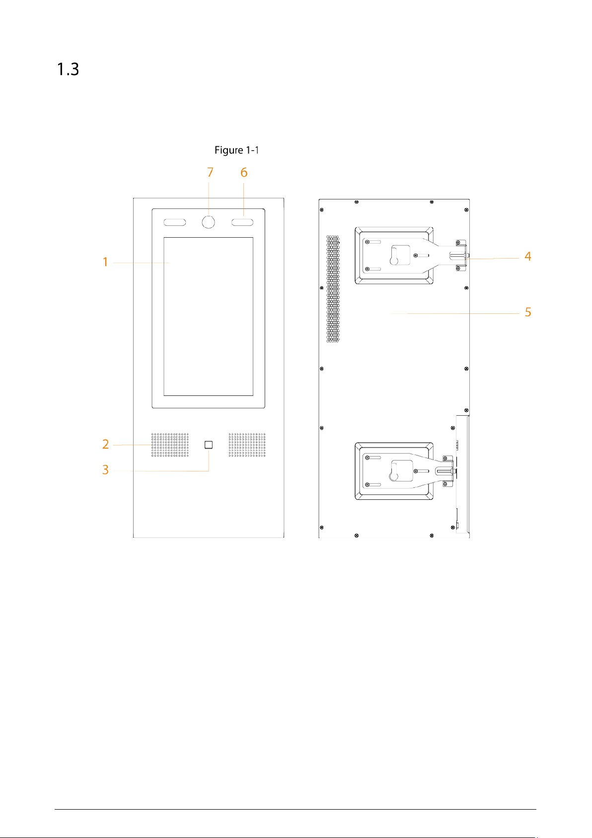
Product Appearance
1.3.1 Control Module
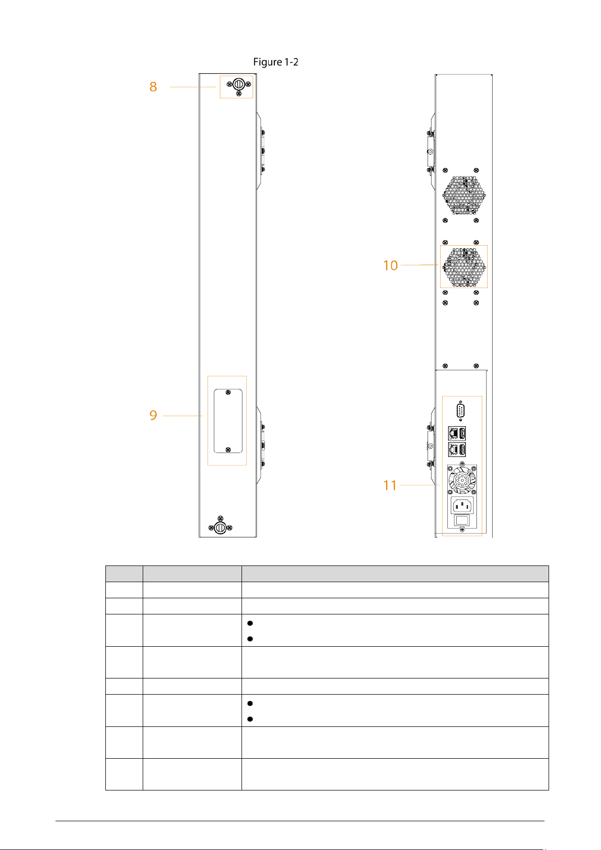
Front panel and rear panel
3
Side panel
Table 1-1 Appearance description
No.
Name
Description
1 Touchscreen 13.3-inch touchscreen.
2 Speaker Audio output.
3 Fingerprint sensor
Add fingerprint data or unlock by fingerprint.
Up to 3 fingerprints can be added for each user.
4 Adjusting board
Remove the control module when connecting control module and
data collection modules.
5 Rear cover —
6 White light
Provides extra light when recognizing faces.
Provides extra light to the camera in dark condition.
7 Camera
Recognizes face information. You can unlock the Station through
face recognition.
8 Axle housing
Connects the control module and data collection modules. One is
at the top, and the other is at the bottom.
4
No.
Name
Description
9 Connector
Transfers the data from control module and data collection
modules.
10
Heat dissipation
hole
—
11 Ports
Include power input port, USB ports, Ethernet ports, and RS-232
port. For details, see Table 1-2.
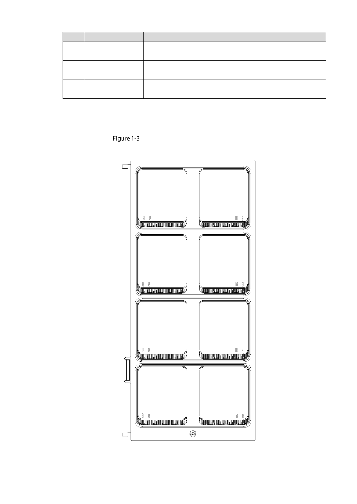
1.3.2 Appearance of Data Collection Modules
Appearance of data collection modules
5
Put body cameras into docks for data collection. When there are more than one data collection
modules, the data of the body cameras in the two docks of the first row will be collected first.
There are two icons below a dock: indicates recharging; indicates collecting data.
When a dock cannot be opened, you can open it with the key.
Description of Buttons
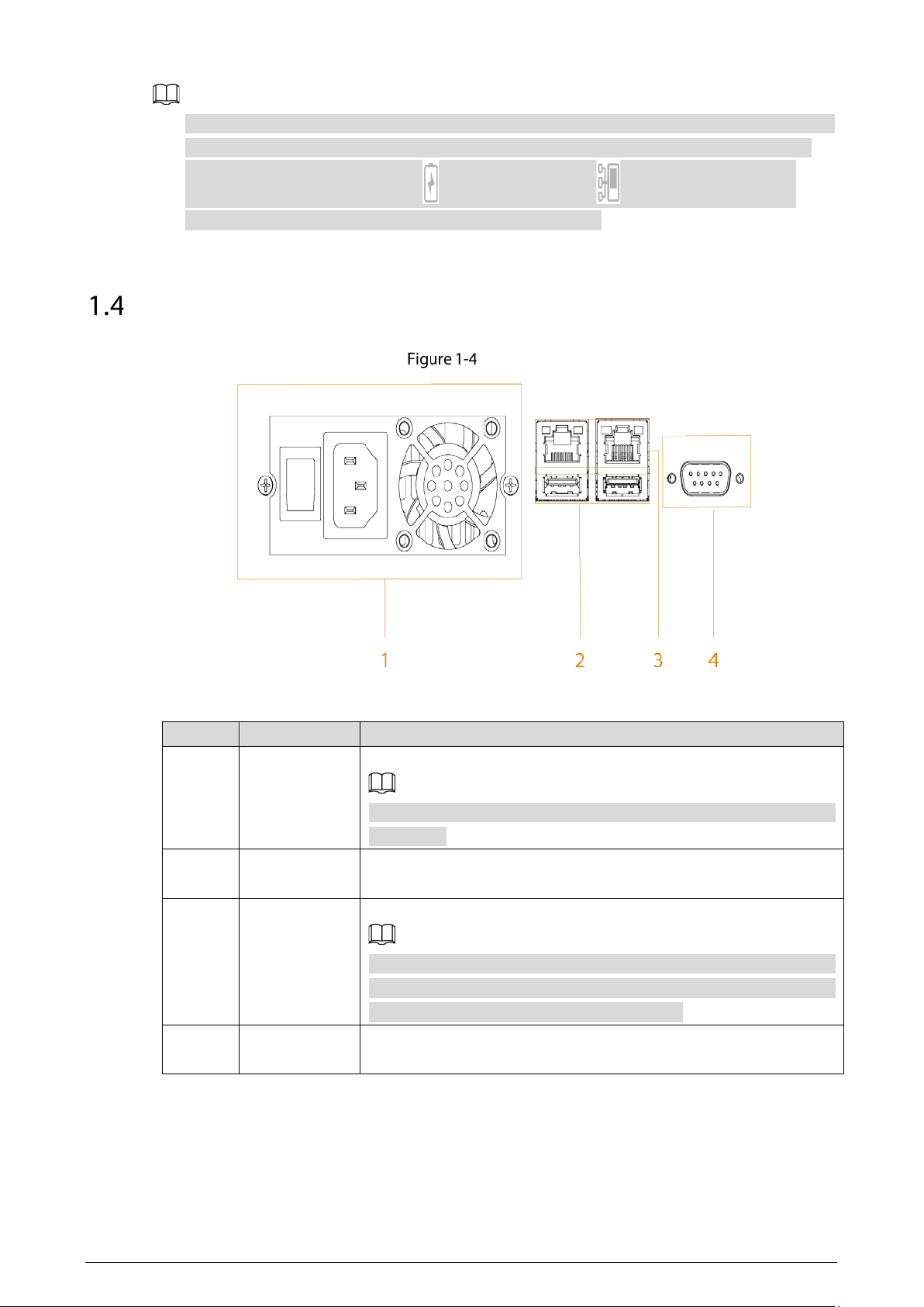
Ports
Table 1-2 Port description
No.
Name
Description
1 Power input
Inputs 100–240 VAC power for the Station.
After shutting down the Station, the fan will work for a period to cool
the Station.
2 USB ports
Connect to USB storage devices (USB 2.0 and USB 3.0), mouse, and
more.
3 Ethernet
2 Gigabit ports.
When you use two ports at the same time, only one port can obtain
the gateway automatically. For the other Ethernet card, disable the
function of obtaining IP address automatically.
4 RS-232
Used for common serial debugging, IP address configuration and
data transmission of transparent serial.

6
Power On
The cover of the Station has static electricity, which might cause electric shock. To avoid electric
shock, make sure the Station is well grounded.
Connect the power cable and network cable.
Press the power button.
The whole process will take a period of time. Please be patient.
7
2 Device Connection
Connecting Control Module and Data Collection Module
You can connect 4 data collection modules to the control module at most.
For the installation details, see the instructions on the positioning map.
Fix the control module on the wall.
Stick the positioning map of data collection module on the wall.
Fix the data collection module according to the instruction on the positioning map.
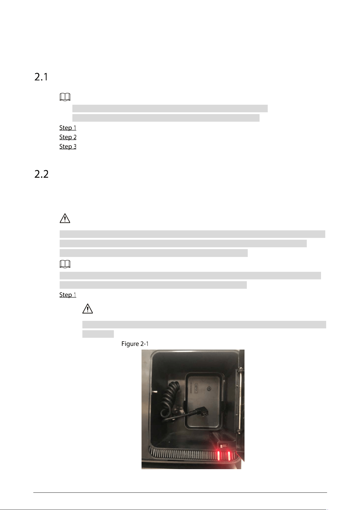
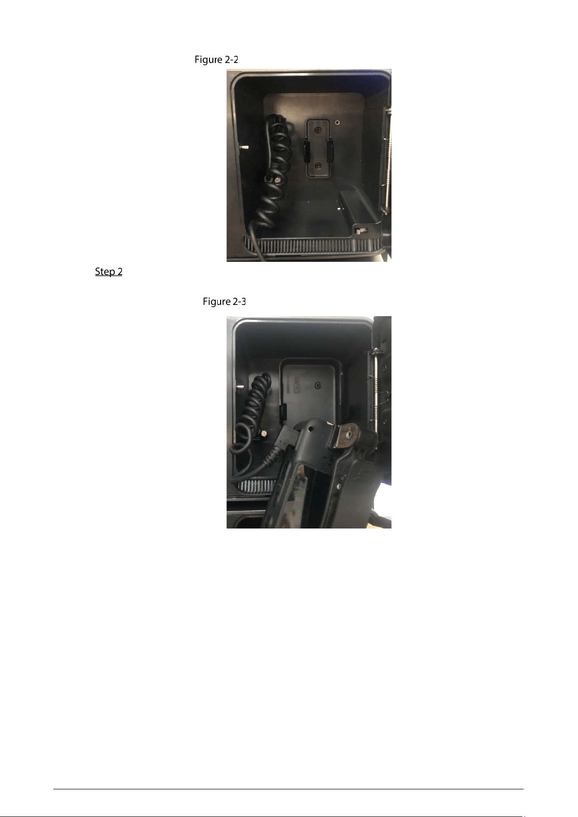
Connecting Body Camera and Data Collection Module
After starting the Station, connect body cameras to the Station, and then you can collect data from
body cameras and recharge them.
Make sure that the connection of body cameras and data collection module is proper, and the body
cameras are placed in slots correctly. If the body cameras are not placed in slots properly, the
cameras might drop when docks open, or the docks cannot be opened.
The slots are designed exclusively for MPT220 body camera by default. If you want to use them for
MPT210 body camera, use the separate slot in the accessories package.
Open the dock through the touch screen or the key, and then take out the data cable.
Do not violently pull data cable. Otherwise, it might result in invalid spring or loosening port
connection.
Take out data cable (MPT220 slot)
8
Take out data cable (MPT210 slot)
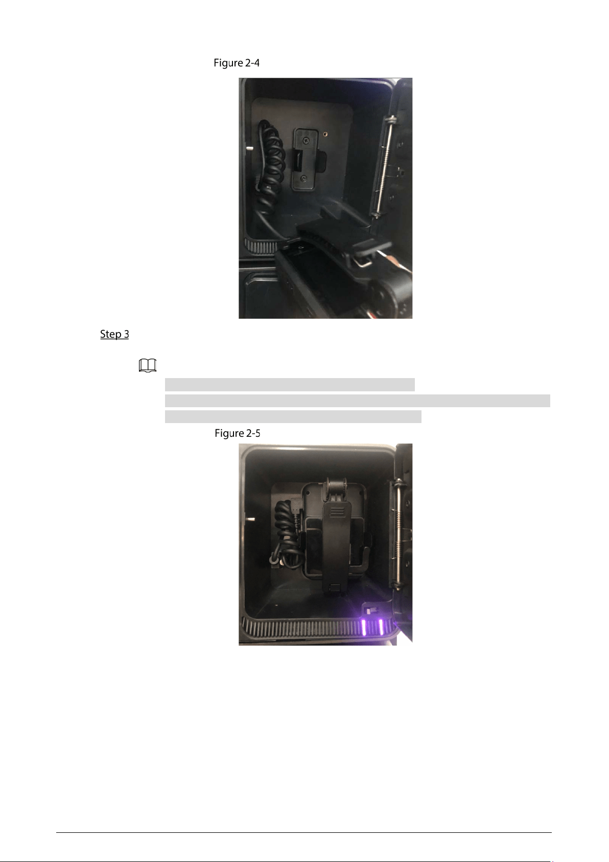
Connect the data cable to the body camera until the Station pops up the connection
successful dialog box.
Connect device (MPT220 slot)
9
Connect device (MPT210 slot)
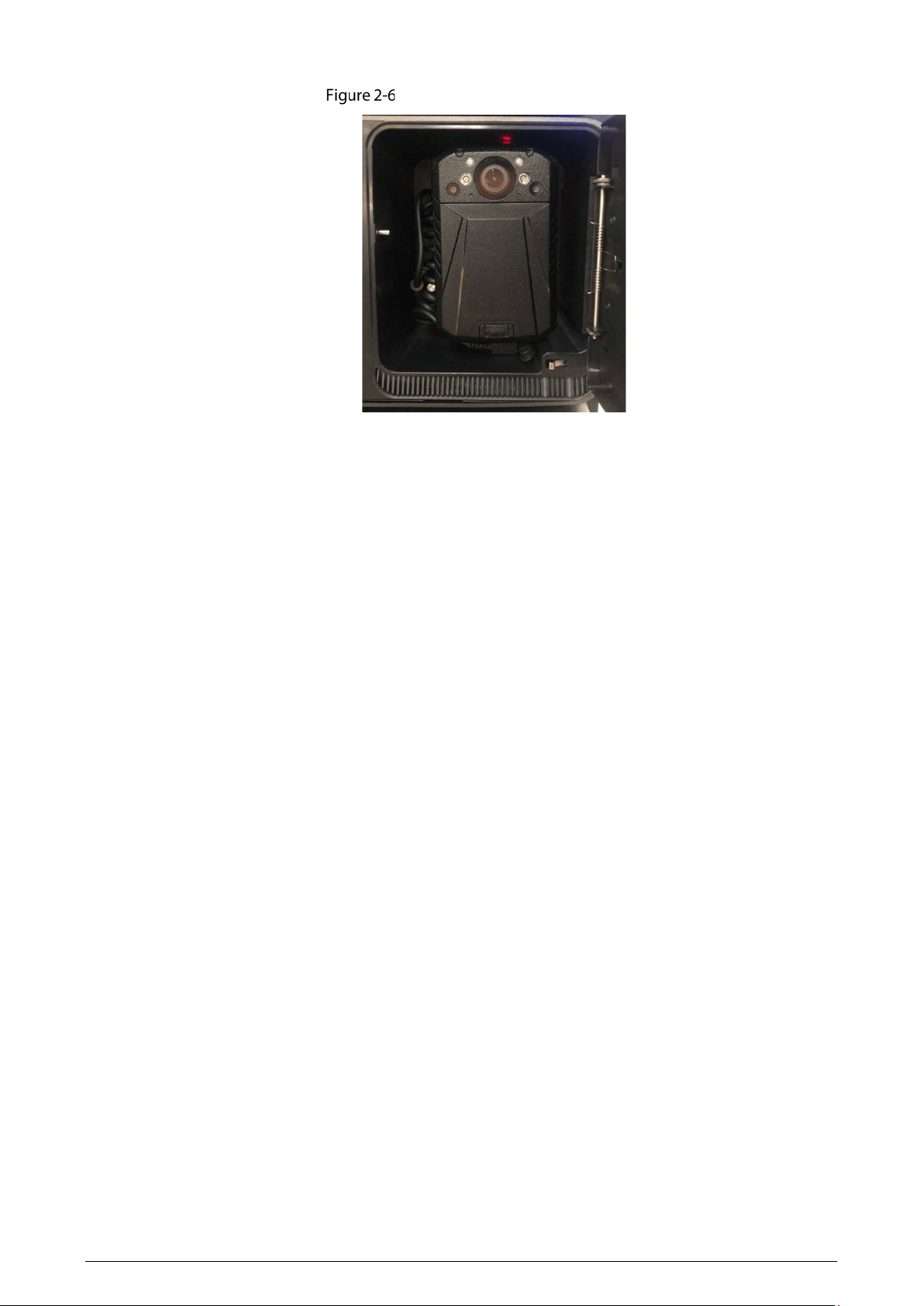
After the connection, put the body camera into the dock, and then you can collect data and
recharge the body camera.
For MPT220 body camera, insert the device into the slot.
For MPT210 body camera, insert the clip into the slot. Only MPT210 body camera with
the latest clip can be inserted into the slot. See Figure 2-4.
Data collection (MPT220 slot)
10
Data collection (MPT210 slot)
11
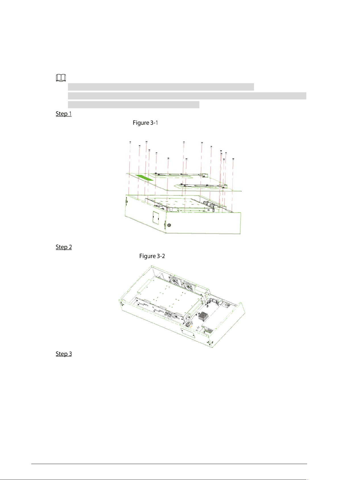
3 HDD Installation
You can install six 10T HDDs (hard disk drives).
To avoid insufficient storage space, HDDs larger than 2T are recommended.
To reduce the writing pressure of each HDD, we recommend you to install at least 2 HDDs with
the same capacity for data collection and recharging.
Loosen the screws on the rear cover, and then remove the rear cover.
Remove rear cover
Disconnect the cables between main board and HDD plate.
Loosen cable
Loosen the four fixed screws on the HDD box, and then take out the box.
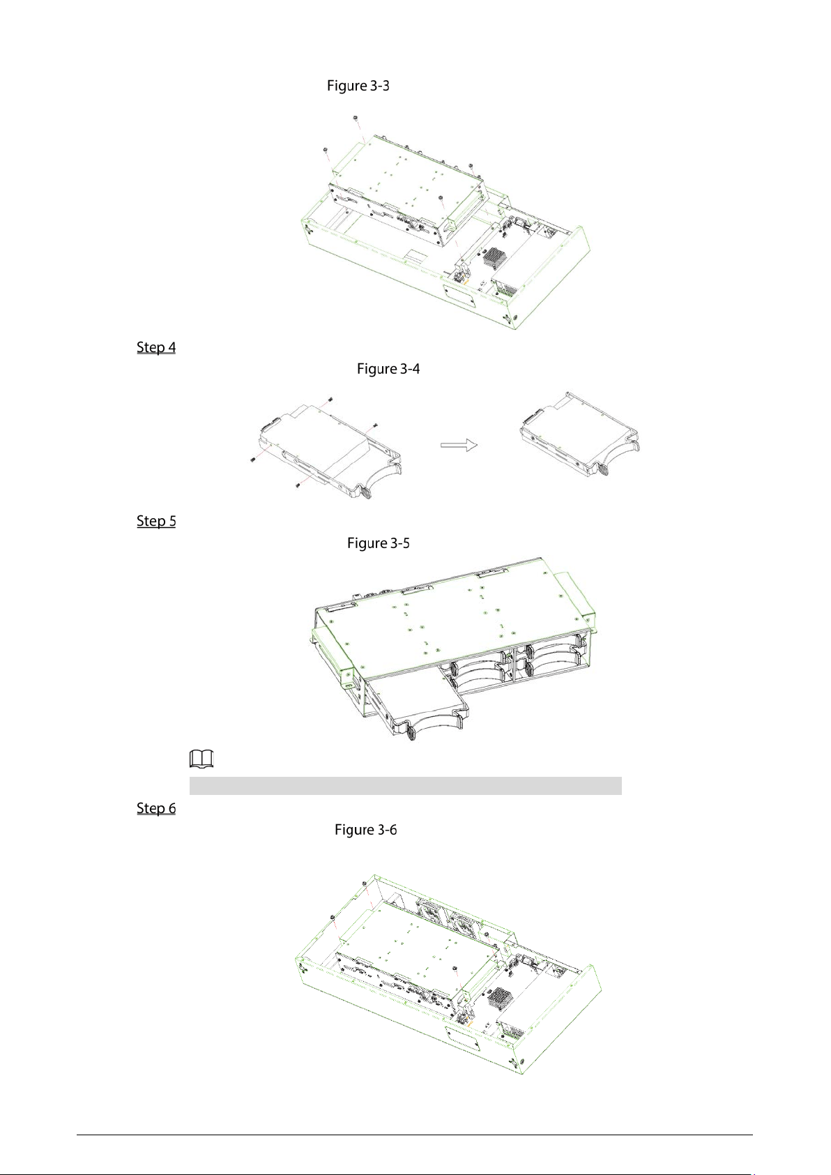
12
Take out HDD box
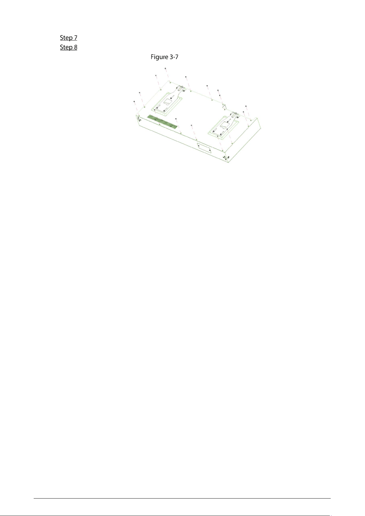
Fix HDDs.
Fix HDD
Install HDDs. Push the fixed HDDs in the HDD box.
Install HDD
Push HDDs in the direction as the HDD port and main board port show.
Fix the HDD box in the chassis.
Install HDD box
13
Connect the cable between main board and HDD plate.
Fix the cover.
Fix the cover
14
4 Configuration and Operation
General
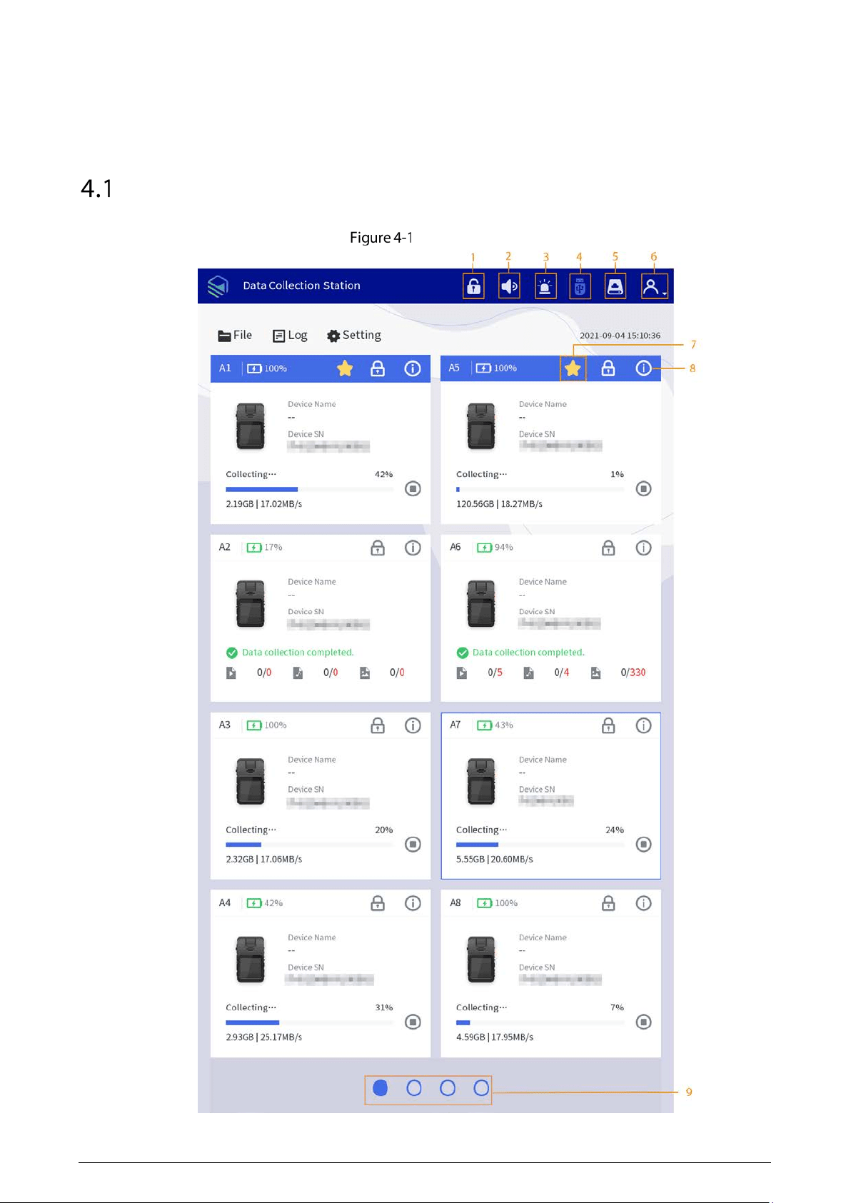
Home screen
15
Table 4-1 Home screen description
No.
Description
1 Unlock the dock by one tap.
2 Alarm. Tap it, and the alarm tune is disabled.
3 Alarm information display. The red light flashes when there is alarm.
4 External USB storage device. Grey means no USB storage device is connected.
5 View HDD capacity.
6 Login, logout, restart, shutdown, and editing the user information.
7
indicates collecting data in priority, which can improve the collecting speed of the
corresponding dock.
To enable this function, you need to connect at least two data collection modules. The
function is supported by the two docks of the first row in each data collection module.
8
View update methods of the Station and body cameras.
Tap
Bind Enforce
on the
Device Info
screen, enter the enforcer name and enforcer No.,
tap
Search
, and then select the enforcer that you want to bind.
9 Switch screens of data collection modules. It supports 4 screens at most.
4.1.1 Login
Before using face login or fingerprint login, you need to complete related configurations. For details,
see "4.1.4.1 User".
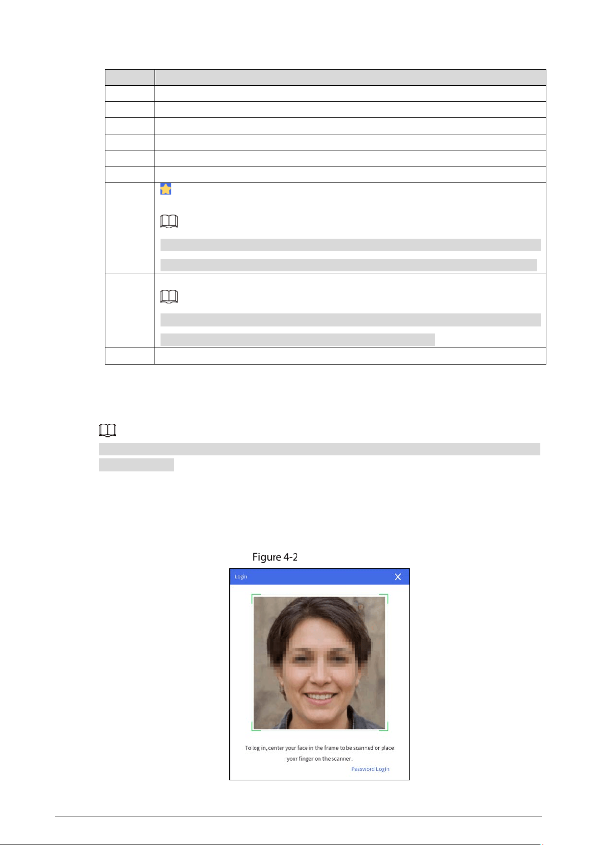
Face Login
After the Station starts, place your face in the detection frame.
After unlocked, the Station displays the home screen.
Face login
16
Fingerprint Login
After the Station starts, place your finger on the scanner.
After unlocked, the Station displays the home screen.
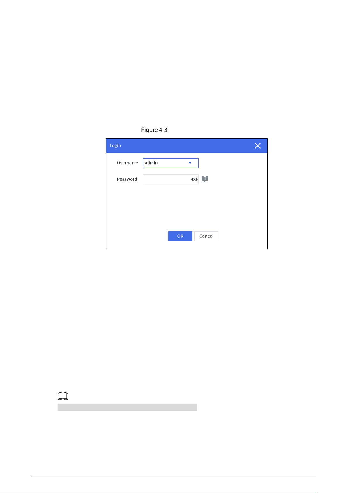
Password Login
After the Station starts, tap Password Login on the lower-right corner of the Login screen, and then
enter username and password.
After unlocked, the Station displays the home screen.
Password login
4.1.2 File Management
4.1.2.1 File Collection
After collecting data files from body cameras, the Station will upload the files to the platform according
to the configuration in
Storage.
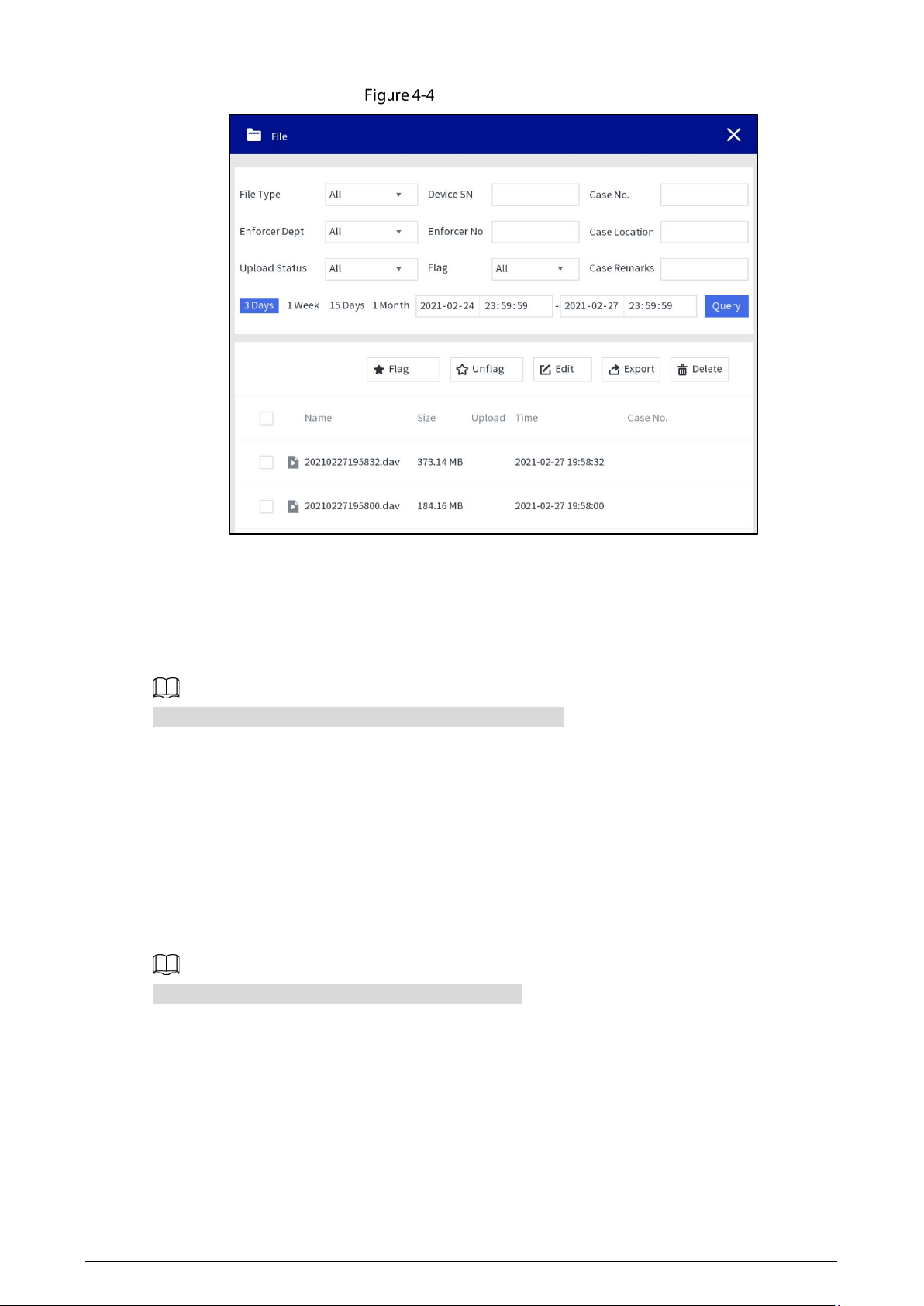
4.1.2.2 Searching for Files
You can search for video files, audio files and snapshots according to the configured conditions,
including file type, enforcer department, upload status, device SN, enforcer No, flag, case No., case
location, case remarks, start time, and end time.
The maximum time range for file searching is 1 month.
17
Searching for files
4.1.2.3 Viewing Files
Double-tap a file to view the details, and you can do the operations of fast play, slow play, zoom in or
zoom out.
You cannot fast play or slow play an audio file in AMR format.
4.1.3 Searching for Logs
You can view local logs, device logs, collection logs and upload logs.
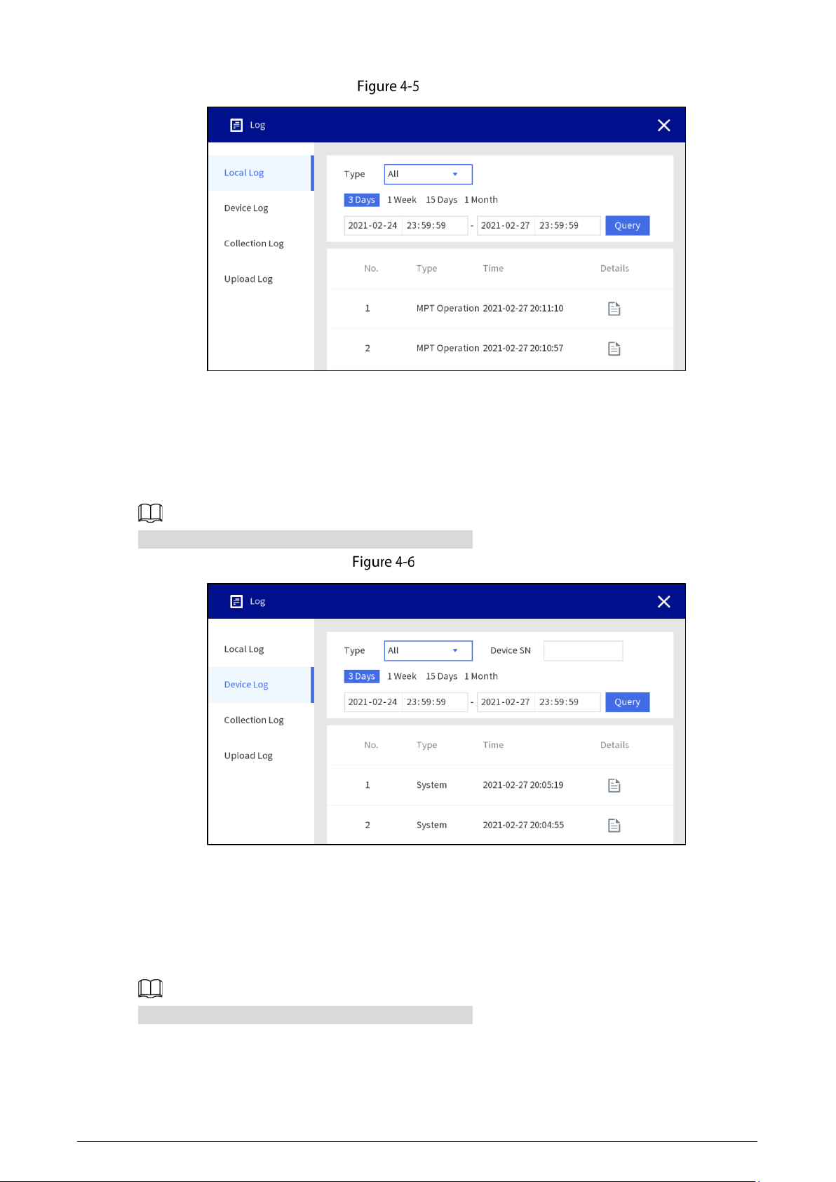
4.1.3.1 Local Log
Select Log > Local log, select the log type, enter the start time and end time, and then tap Query.
The maximum time range for log searching is 1 month.
18
Local log
4.1.3.2 Device Log
Select Log > Device log, select the log type, enter device SN, start time and end time, and then tap
Query.
The maximum time range for log searching is 1 month.
Device log
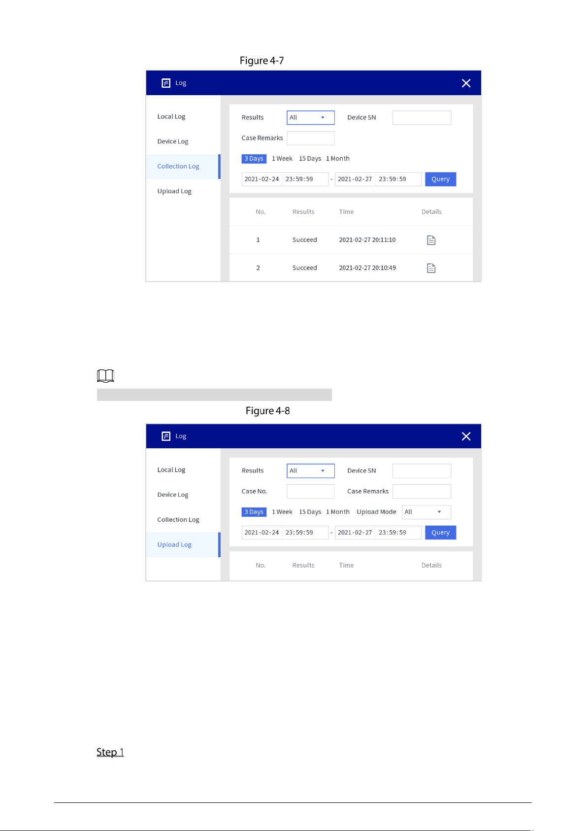
4.1.3.3 Collection Log
Select Log > Collection Log, select results, enter device SN, case remarks, start time and end time,
and then tap
Query.
The maximum time range for log searching is 1 month.
19
Collection log
4.1.3.4 Upload Log
Select Log > Upload log, select the result, enter device SN, case No., case remarks, start time and end
time, and then tap
Query.
The maximum time range for log searching is 1 month.
Upload log
4.1.4 Local Settings
4.1.4.1 User
Administrator can add user, delete user and edit user permissions.
4.1.4.1.1 User Management
Select Setting > Account > User.
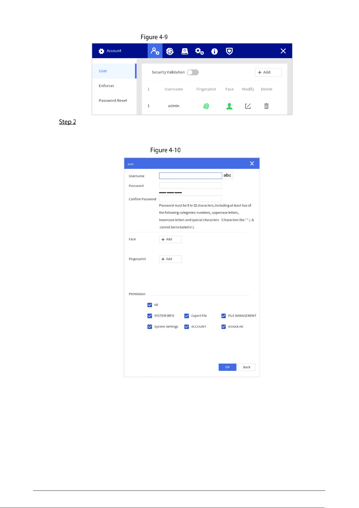
20
User management
Tap Add to add users.
You can add faces and fingerprints, and configure user permissions. All permissions are
enabled by default.
Add users
4.1.4.1.2 Enforcer Management
Select Setting > Account > Enforcer.
Adding Enforcer
Tap Add to add users. Enter enforcer department, enforcer No., enforcer name, password, and confirm
password, and add face and fingerprint.
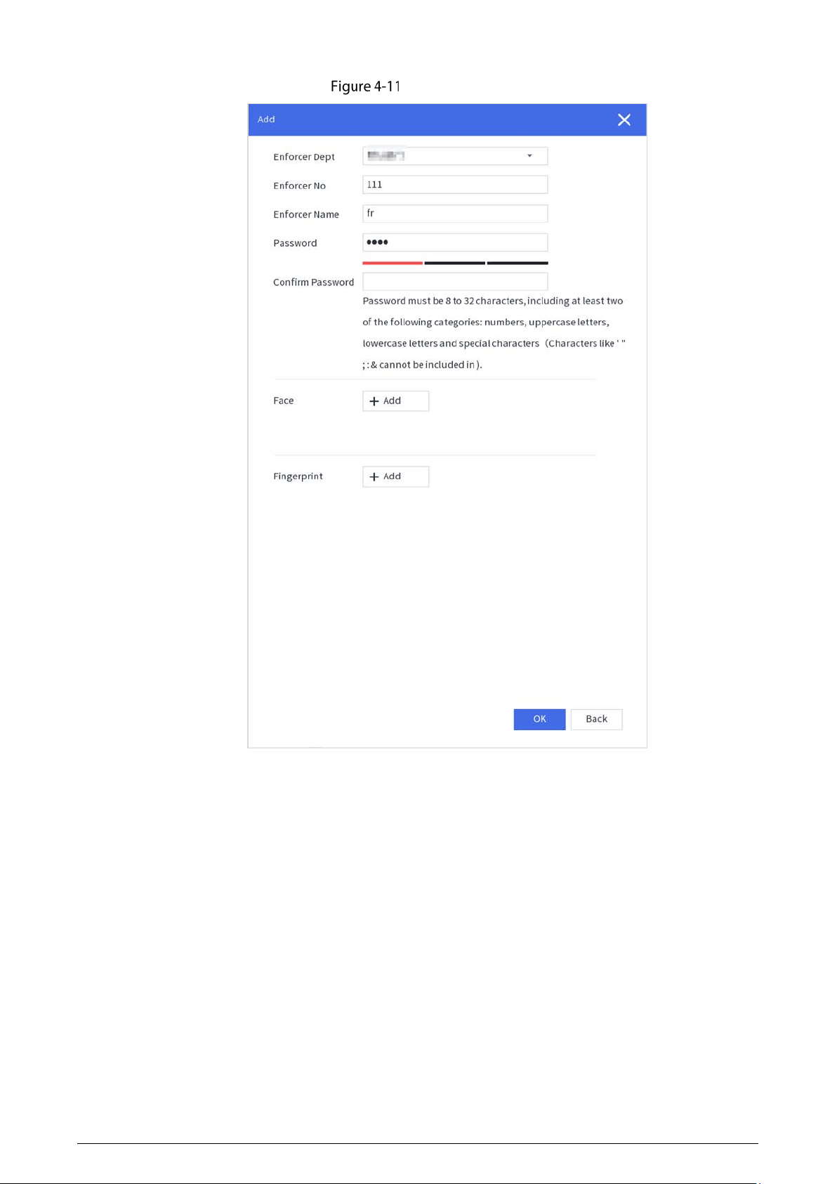
21
Adding enforcer
Searching for Enforcer
You can search for enforcer through enforcer department, enforcer name, and enforcer No.
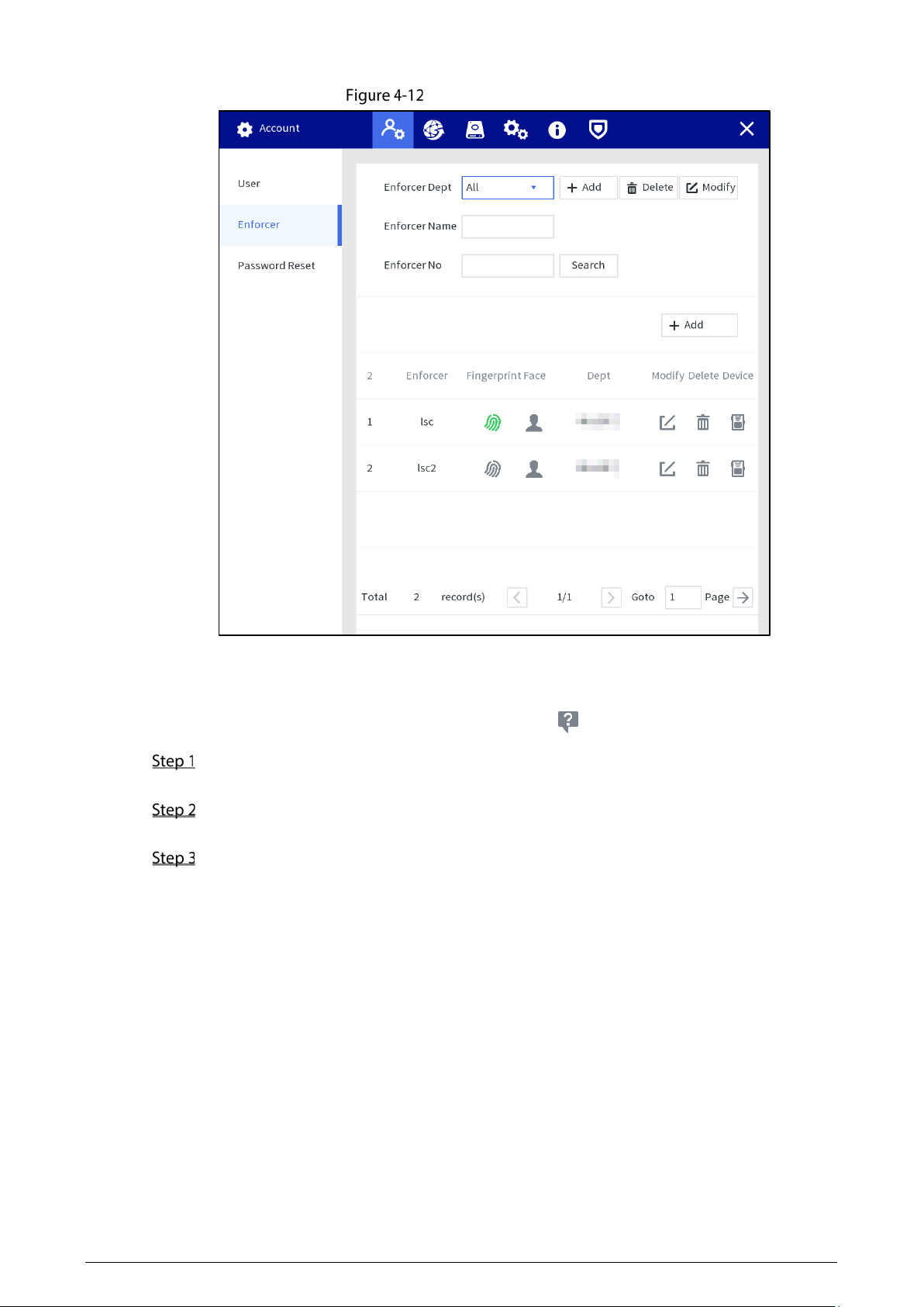
22
Searching for enforcer
4.1.4.1.3 Resetting Password
Enable the function, and you can reset password by taping on the login screen.
Select Setting > Account > Password Reset, and enable the password resetting function.
If the function is not enabled, you can only reset the password by resetting the Station.
Enter the recovery email address and the security questions.
If you want to modify security question after successful setting, tap Reset first.
Tap Apply.
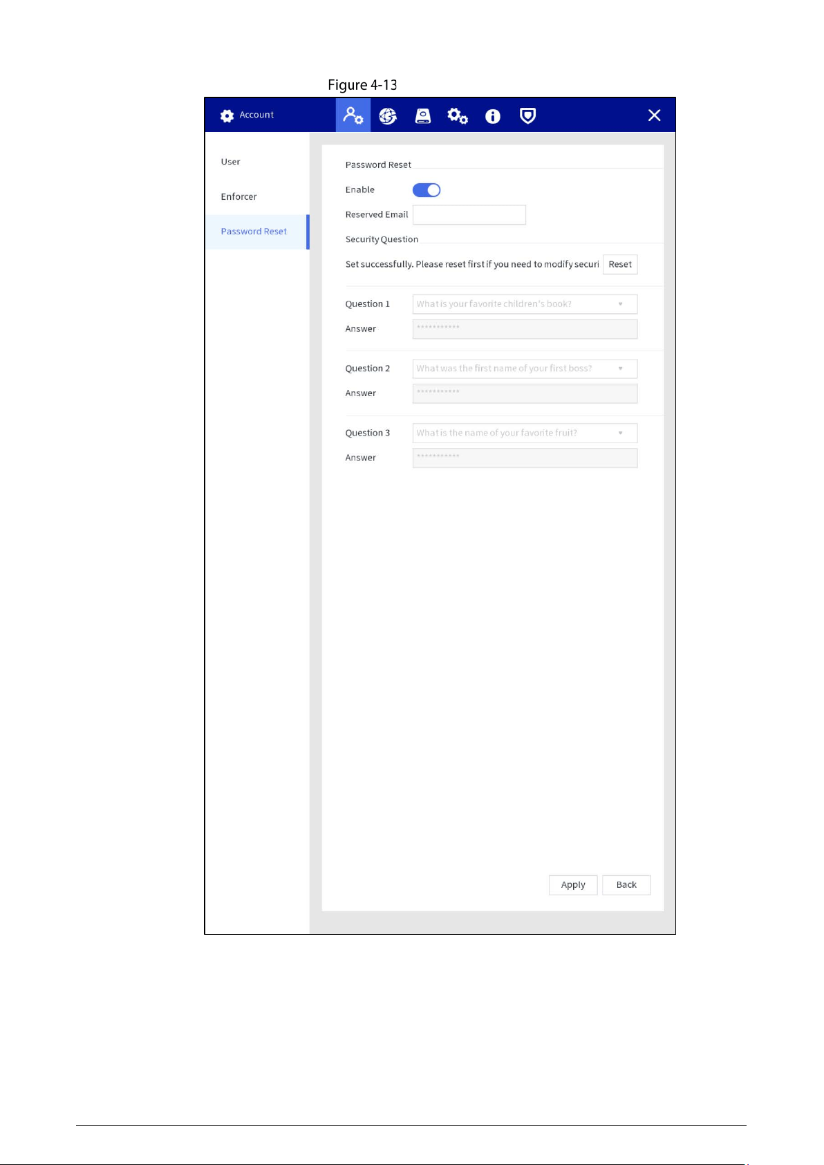
23
Reset password
24
4.1.4.2 Network Management
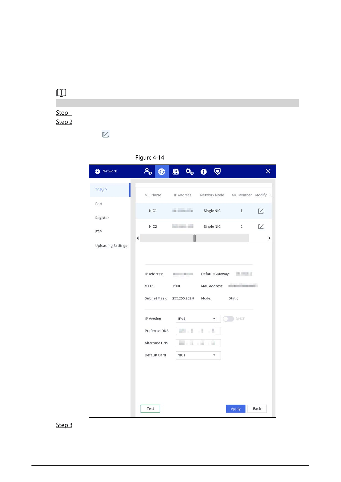
4.1.4.2.1 TCP/IP
You can configure IP address and DNS (Domain Name System) server and other information according
to network planning.
Make sure at least one Ethernet port has connected to the network before configuring IP address.
Select Setting > Network > TCP/IP.
Configure Ethernet card parameters.
1) Tap of the corresponding Ethernet card.
2) Configure Ethernet card parameter.
IP configuration
Tap Apply.
25
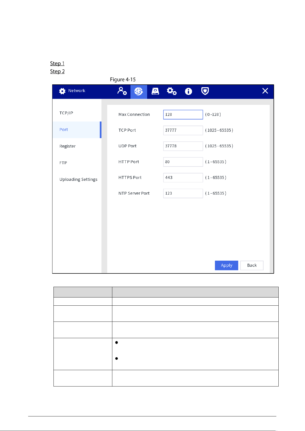
4.1.4.2.2 Port
Configure the port numbers and the maximum number of users (includes web and platform) that can
connect to the device simultaneously.
Select Setting > Network > Port.
Configure port parameters.
Configure port parameter
Table 4-2 Port parameters description
Parameter
Description
Max Connection Enter the max. connection number. It ranges from 0 to 128.
TCP Port
Enter the number as needed. It is 37777 by default, and ranges from
1025 to 65535.
UDP Port
Enter the number as needed. It is 37778 by default, and ranges from
1025 to 65535.
HTTP Port
Enter the number as needed. It is 80 by default, and ranges from 1
to 65535.
If the value you set is not 80, add the port number after the IP
address when you are using browser to log in to the device.
HTTPS Port
Enter the number as needed. It is 443 by default, and ranges from 1 to
65535.
26
Parameter
Description
NTP Server Port
Enter the number as needed. It is 123 by default, and ranges from 1 to
65535.
Tap Apply.
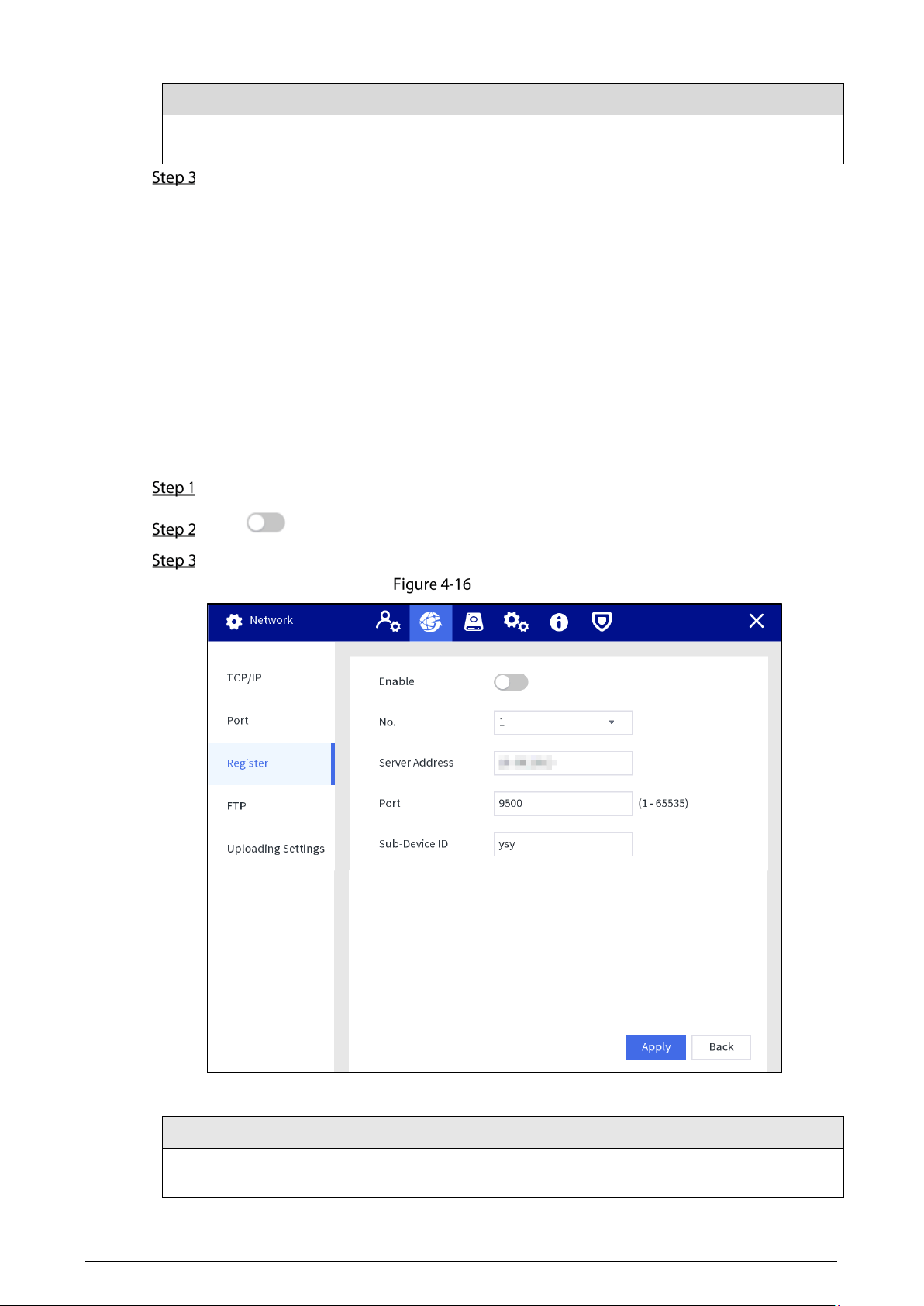
4.1.4.2.3 Register
Register the Station to a designated proxy server which acts as the transit to make it easier for the
client software to access the Station.
Prerequisites
The proxy server is deployed.
The Station, the proxy server, and the device running the client software are on the same network.
Procedure
Select Setting > Network > Register.
Tap to enable the function.
Configure the parameters.
Register
Table 4-3 Register parameters
Parameter
Description
Server Address Enter the server IP address or the server domain that you want register to.
Port Enter the port of the server.
27
Parameter
Description
Sub-Device ID This ID is allocated by the server and used for the Station.
Tap Apply.
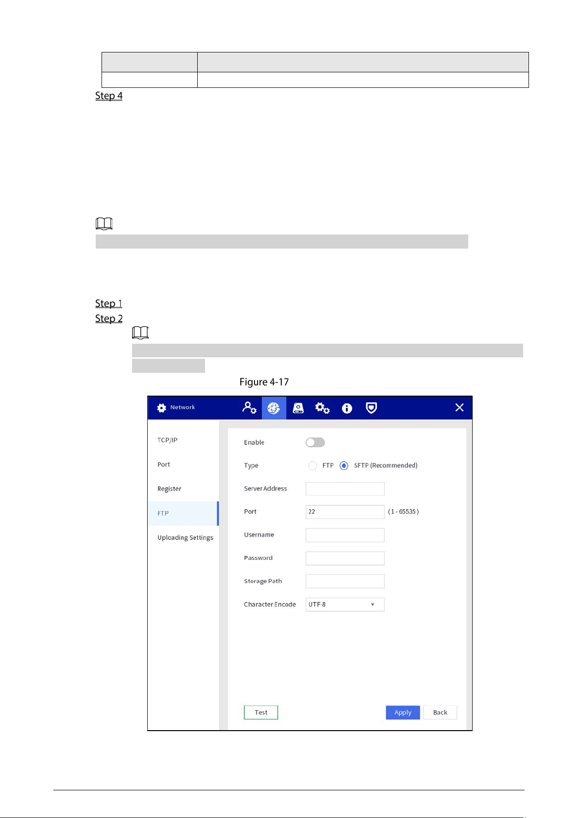
4.1.4.2.4 FTP Setting
Configure FTP server, and then you can save videos, audios and snapshots in the FTP server.
Prerequisites
You have deployed a FTP server, and created a user with the read & write permission.
The created FTP user should have write permission; otherwise the file uploading will fail.
Procedure
Select Setting > Network > FTP.
Enable FTP, select FTP type, and then configure parameters.
You can select FTP or SFTP from the drop-down list. SFTP is recommended to enhance
network security.
FTP setting
28
Table 4-4 FTP parameters
Parameter
Description
Server Address The IP address of the FTP server.
Port
The port number of the FTP server.
The default port is 22 for SFTP, and the default port is 21 for FTP.
Username
The username and password used to log in to the FTP server.
Password
Storage Path
The destination path in the FTP server.
Create folder on FTP server.
If you do not enter the name of remote directory, the system
automatically creates the folders according to the IP and time.
If you enter the name of remote directory, the system creates the folder
with the entered name under the FTP root directory first, and then
automatically creates the folders according to the IP and time.
Character Encode
Supports UTF-8 and GB2312.
When messy codes are displayed on the server, switch the character encode.
Tap Apply.
4.1.4.3 Storage Management
You can manage the storage resources (such as recording files) and storage space to enhance storage
space usage and data security.
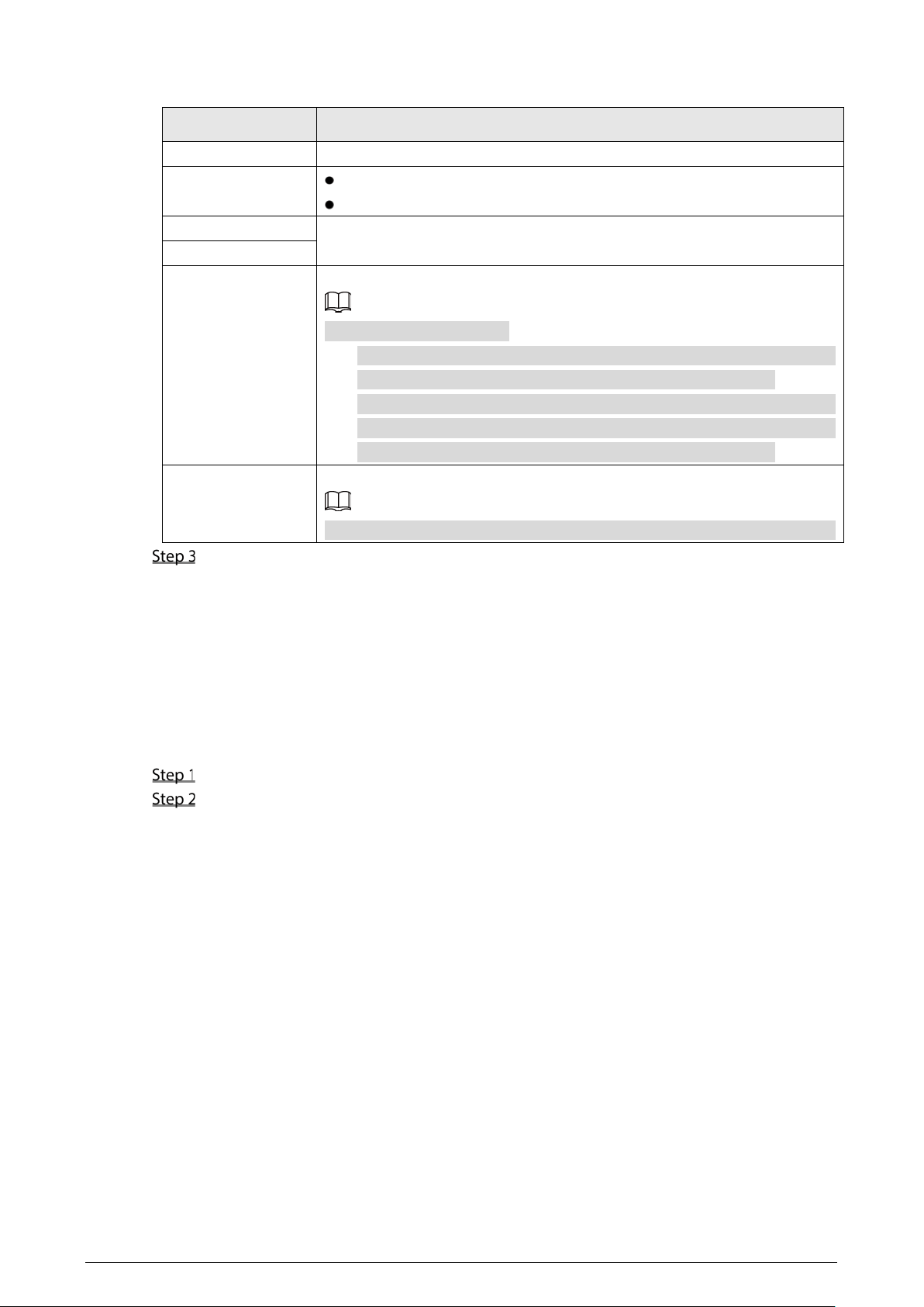
4.1.4.3.1 Basic
Select Setting > Storage > Basic.
Configure parameters.
Disk Full: Configure the settings for the situation that all the read/write disks are full, and
there is no more free disk.
Select
Stop Record to stop recording.
Select
Overwrite to overwrite the recorded video files always from the earliest time.
Overwrites files that are not uploaded: If this function is disabled, files that are not
uploaded will not be overwritten.
29
Basic configuration
Tap Apply.
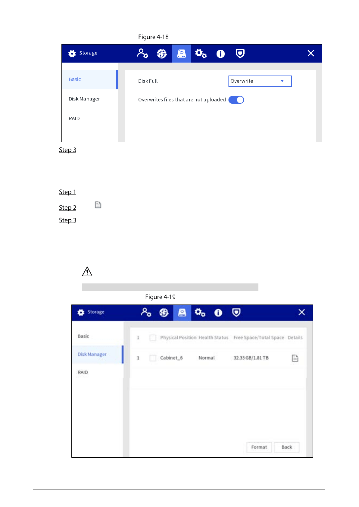
4.1.4.3.2 Disk Manager
You can view disk information, format disk, and set the disk type according to the actual situation.
Select Setting > Storage > Disk Manager.
Tap to view the details.
(Optional) Format an HDD.
1) Select an HDD and then tap Format.
2) Tap
OK.
3) Enter the admin password and tap
OK.
All data in the HDD is deleted.
This operation will delete all data in the HDD. Proceed with caution.
Disk manager
30
4.1.4.3.3 RAID
RAID (redundant array of independent disks) is a data storage virtualization technology that combines
multiple physical HDD components into a single logical unit for the purposes of data redundancy,
performance improvement, or both.
The Station supports RAID0, RAID1, RAID5, RAID10. For details, see "Appendix 1 RAID ". This
section takes RAID 5 as an example.
We recommend deploying RAID disk at the beginning of RAID configuration. Creating or deleting
RAID will affect device data.
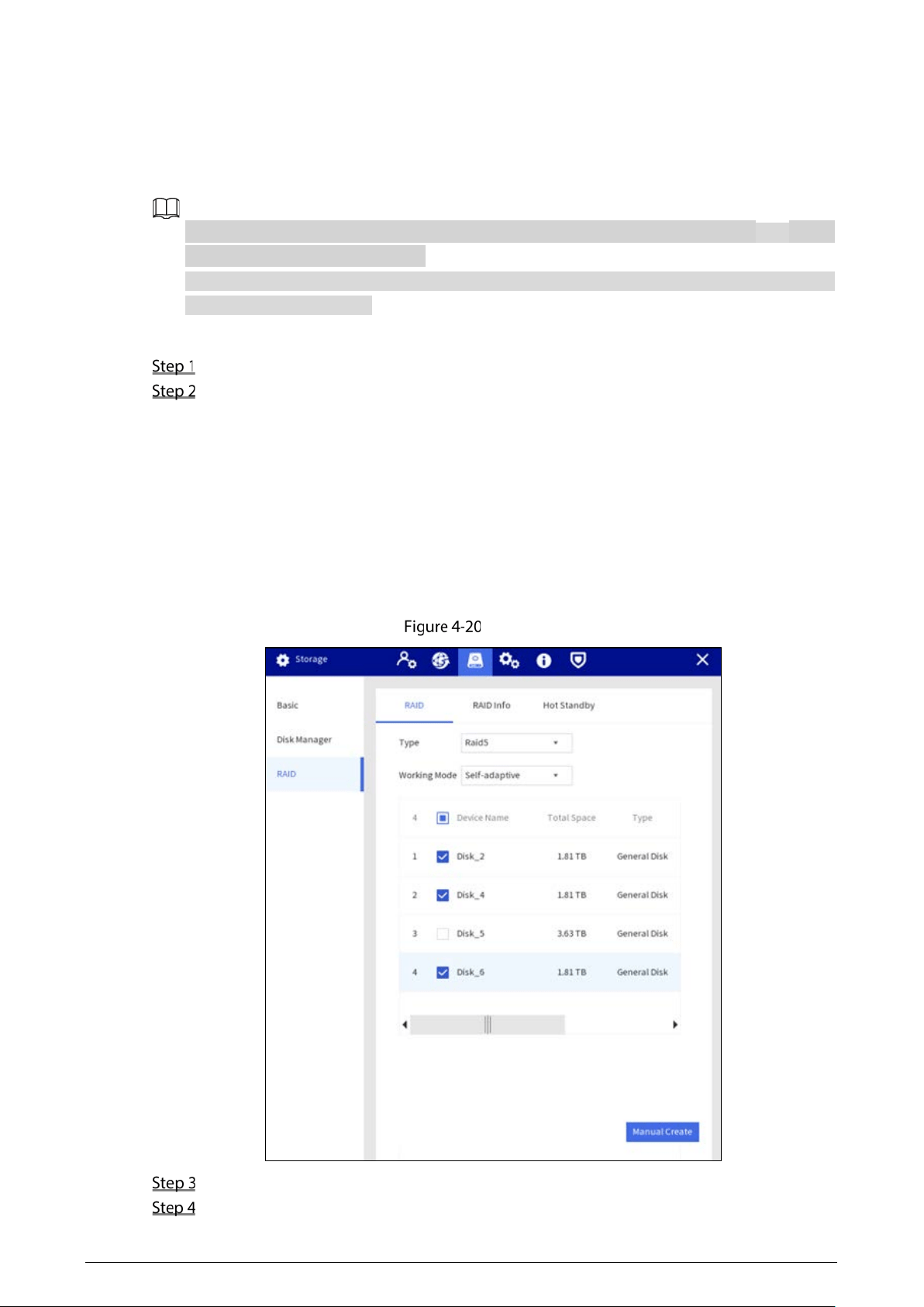
Configuring RAID
Select Setting > Storage > RAID > RAID.
Select RAID type and working mode.
When you select RAID 5 in Type, you can set the work mode.
Self-adaptive: The system can automatically adjust RAID synchronization speed
according to current business load. When there is no external business running, the
synchronization is performed at high speed. When there is external business running,
the synchronization is performed at low speed.
Sync first: Resources are allocated to RAID synchronization first.
Business first: Resources are allocated to business first.
Load-balance: Resources are allocated to business and RAID synchronization equally.
RAID
Select the disk where you want to create RAID.
Tap Manual Create.
31
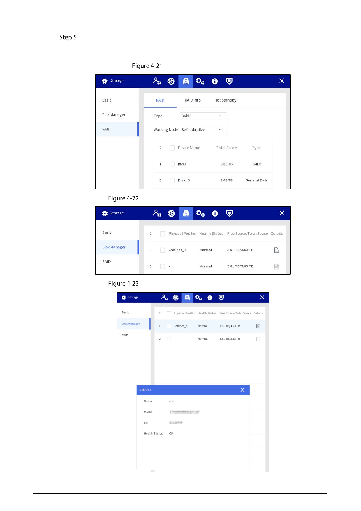
Tap Confirm.
After authentication, RAID is created successfully, and the information of the new RAID is
displayed.
Create RAID successfully
Display in disk manager RAID is created (1)
Display in disk manager RAID is created (2)
32
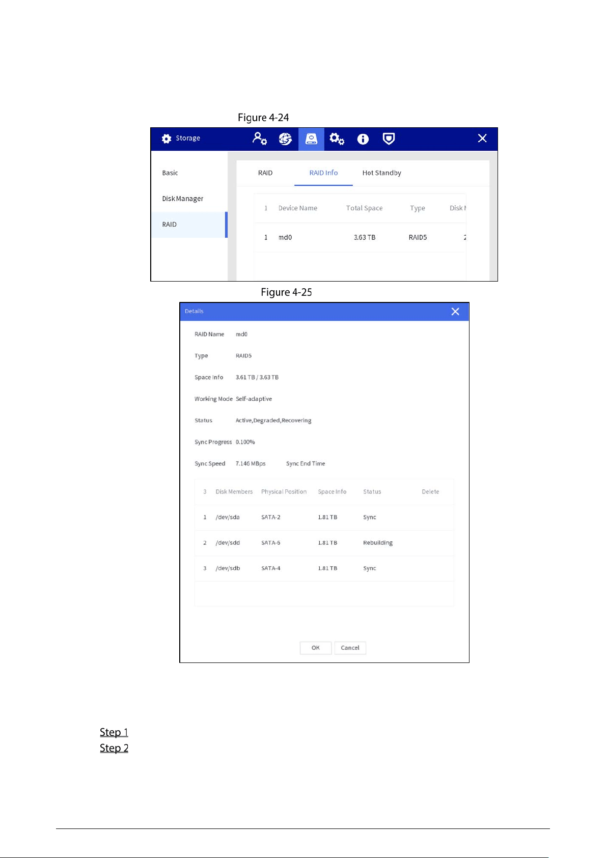
RAID Information
You can view RAID info including device name, total space, and type.
Select
Setting > Storage > RAID > RAID Info, and then tap the RAID to see the details.
RAID information
Details
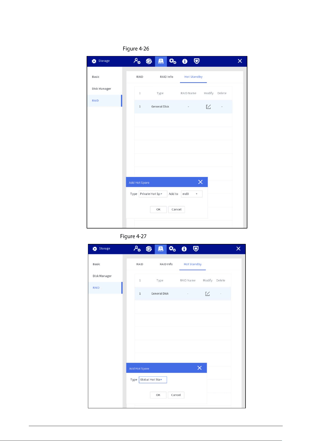
Hot Standby
When an HDD of the RAID group has a problem, the hot spare HDD can replace the malfunctioning
HDD. There is no risk of data loss and it can guarantee storage system reliability.
Select Setting > Storage > RAID > Hot Standby.
Select device type and the RAID group that needs to add hot spare HDD.
Private hot spare: Select a RAID group to be added, and then the HDD will be added to
the corresponding RAID group, and used as a hot spare HDD for the RAID.
33
Global hot standby: It is a hot spare HDD for all RAID groups rather than a specific RAID
group.
Private hot spare
Global hot standby
34
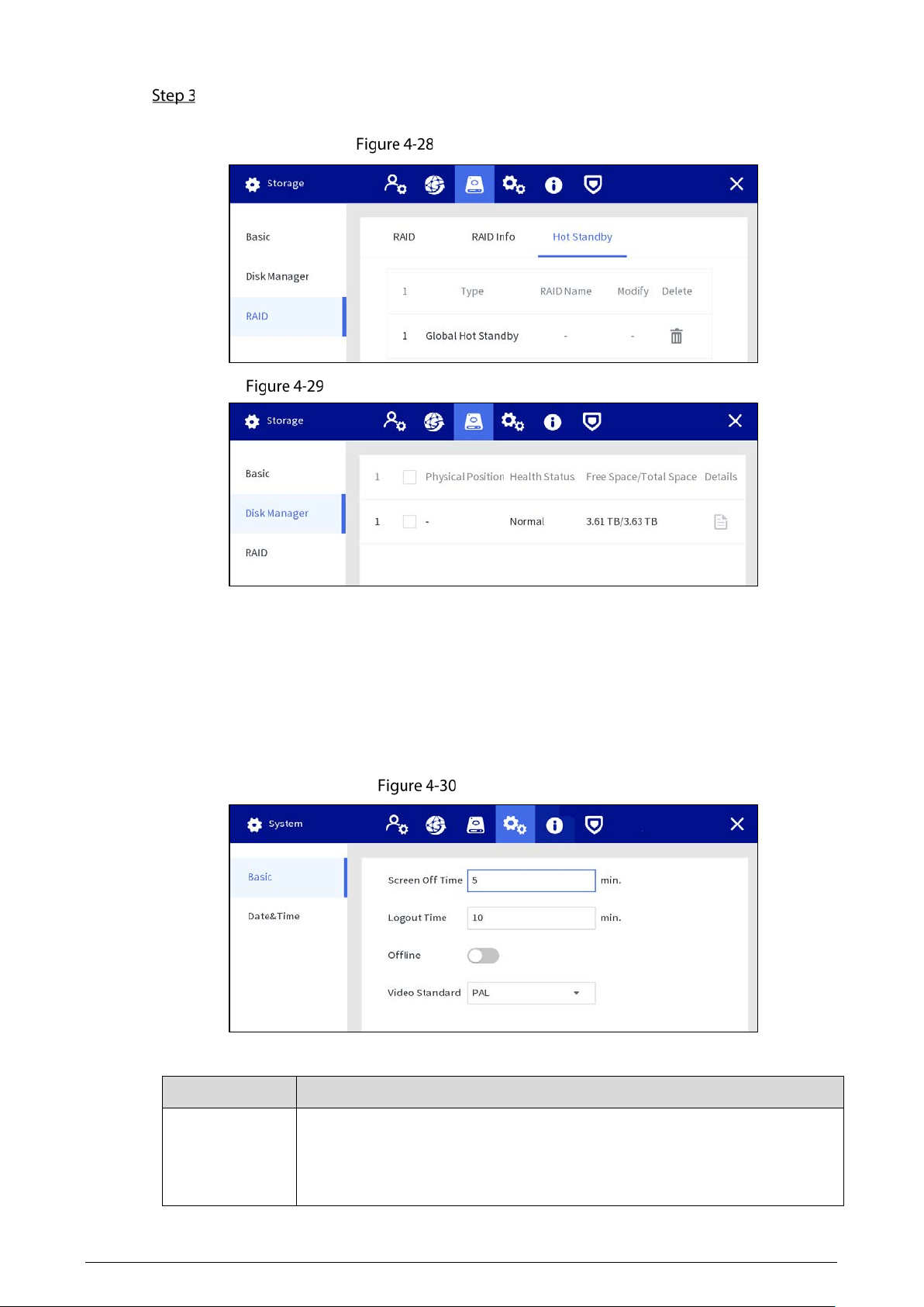
Tap OK.
After authentication, the hot standby is created successfully.
Global hot standby
Display in disk manager after hot standby is created
4.1.4.4 System Management
4.1.4.4.1 Basic Setting
You can set the screen off time, logout time, video standard, and decide whether to trigger alarm when
network disconnection occurs.
Basic setting
Table 4-5 Date and time parameters
Parameter
Description
Screen Off Time
Set the screen off time. When you do not operate the Station within the
defined time, the screen will be off. It ranges from 0–60 minutes, and 0 means
the screen will always be on. To extending service life of the LCD screen, we
recommend you not to set the time as 0 minutes.
35
Parameter
Description
Logout Time
Set auto logout interval.When you do not operate the Station within the set
time, the Station will log out automatically. After auto logout, you need to log
in again to operate. It ranges from 0–60 minutes, and 0 means the Station will
not log out. To guarantee the safety of the Station account, we recommend
you not to set the time as 0 minutes.
Offline
When
Offline
is enabled, an alarm will be triggered when network
disconnection occurs on any Ethernet port.
Video Standard
Select video standard from
PAL
and
NTSC
.
Restart the Station after switching the video standard to make the
configuration take effect.
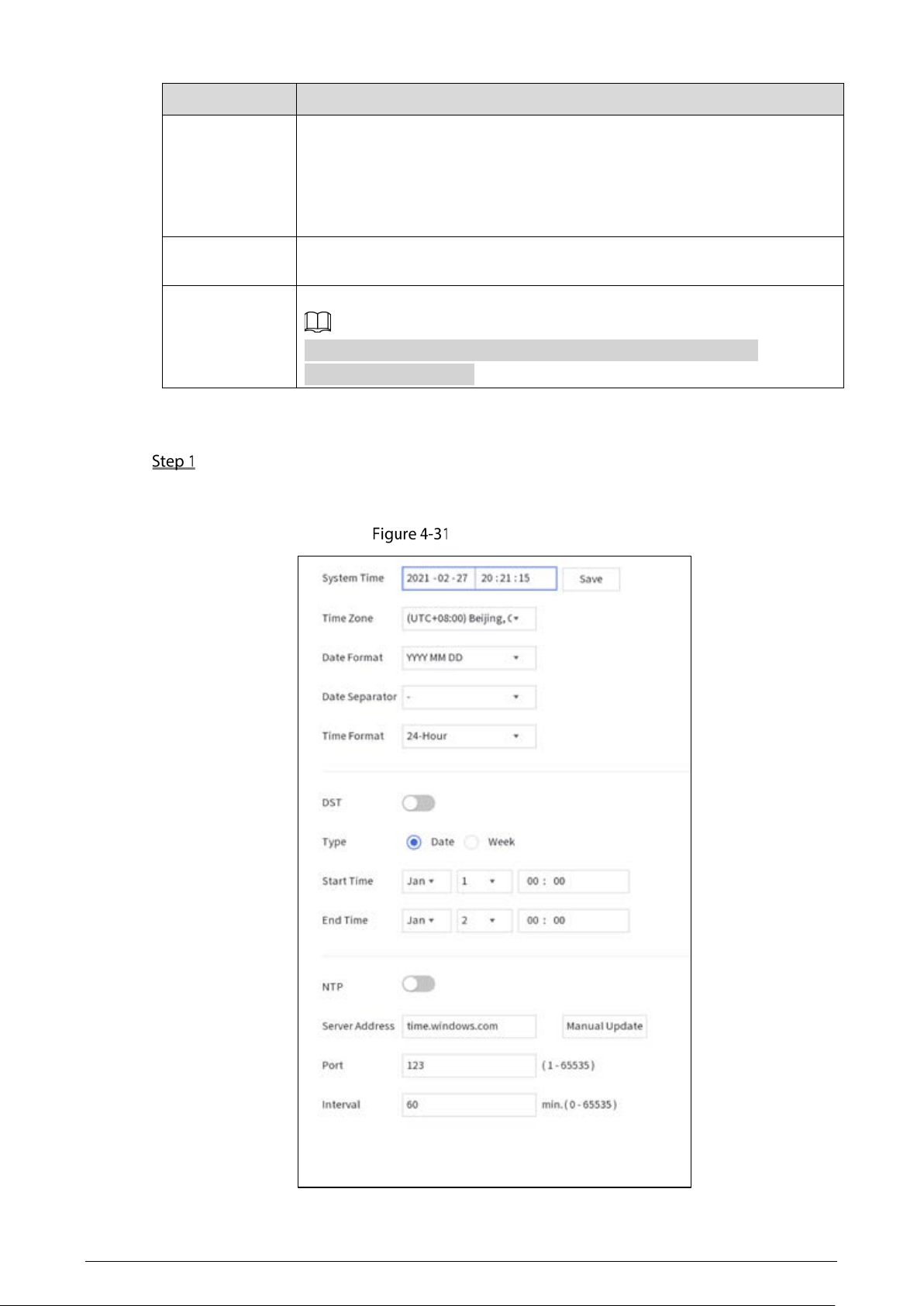
4.1.4.4.2 Date and Time
Select Setting > System > Date&Time.
In the same network, if the time of the body camera is not consistent with that of the Station,
you may not view or play back videos. You can set the time manually or through NTP.
Date and time
36
Set the time manually
Set system time, format, and time zone according to the actual situation.
Table 4-6 Date and time parameters
Parameter
Description
System Time
Set the device system date and time.
Tap
Sync PC
to synchronize time with the PC from where you log in to the
web page.
Time Zone Time zone of the current area.
Date Format Select a date format from
YYY MM DD
,
MM DD YYY
, and
DD MM YYY
.
Date Separator Select a separator between year, month, and date.
Time Format Select a time format from
24-Hour
and
12-Hour
.
DST
When you enable DST, set DST type, start time and end time.
DST is a system to stipulate local time, in order to save energy. The DST is applied
in some countries or regions. Enable or disable DST as needed.
Enable NTP
Enable NTP, and enter the server address, port, and interval. After configuration, the
system adjusts the device time according to the NTP server time.
Interval refers to the time interval that the device synchronizes time with the NTP server.
Tap Apply.
4.1.4.5 Operation & Maintenance Management
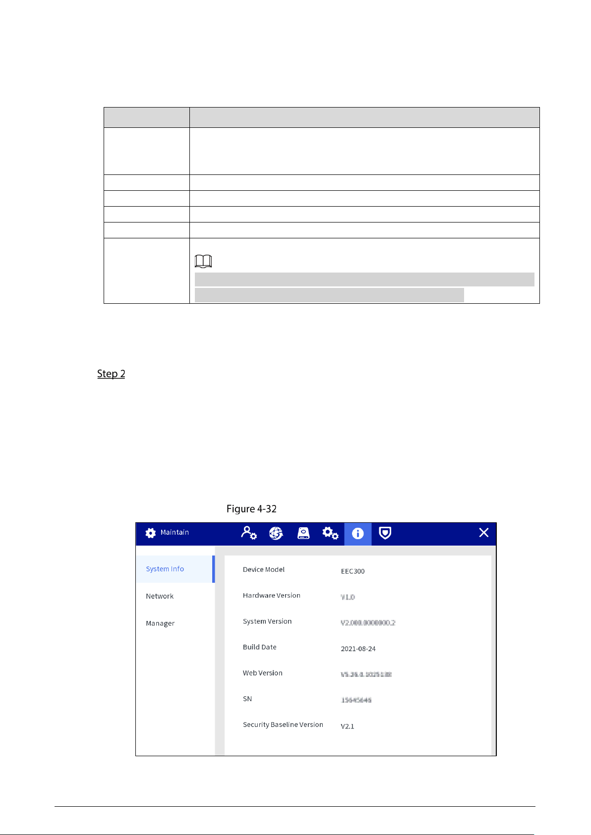
4.1.4.5.1 System Information
You can view the device model, hardware version, system version, and web version.
Select
Setting > Maintain > System Info.
System information
37
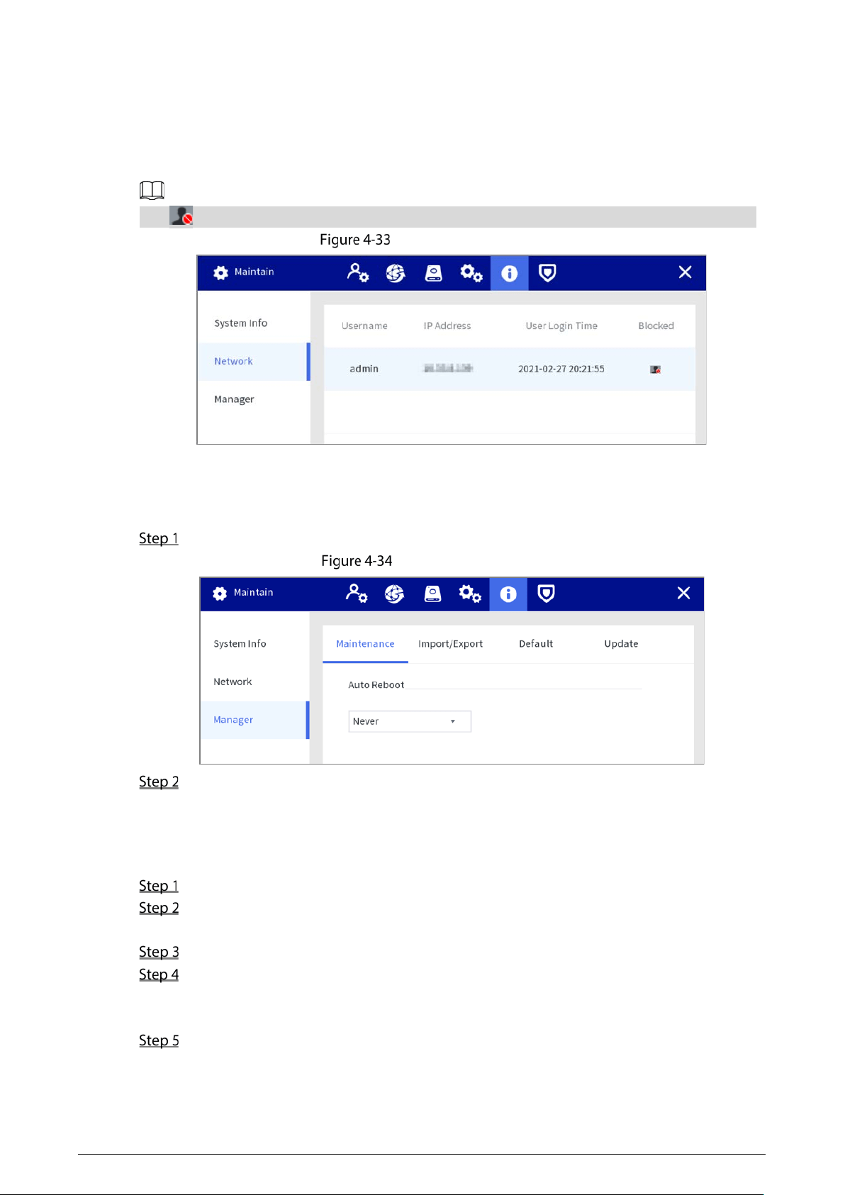
4.1.4.5.2 Network
You can view the information of the user who is accessing the device, and the user list is updated in
real time.
Select
Setting > Maintain > Network.
Tap to block a certain user for a period, and the blocking time can be set up to 65,535 seconds.
Network information
4.1.4.5.3 Maintain
Device Maintain
Select Setting > Maintain > Manager > Maintenance, and then set the maintenance date.
Device maintenance
Tap Apply.
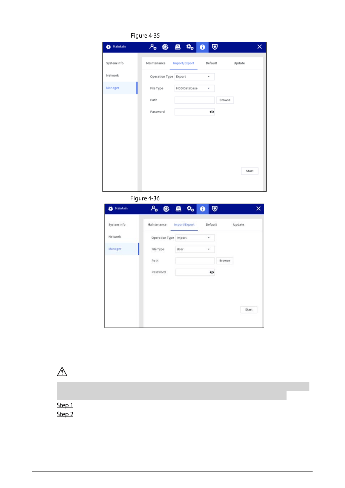
Import/Export
Export the device data and user information for backup. When there is device exception, you can
import the exported data to recover the data.
Select Setting > Maintain > Manager > Import/Export.
Select Export from the Operation Type list, select the file type and storage path, and then
enter the password.
Tap Start.
(Optional) When there is device exception, select Import from the Operation Type list, select
the file type and storage path of the configuration file to be imported, and then enter the
password.
Tap Start.
Import configuration file, and then restart the Station.
38
Export configuration
Import configuration
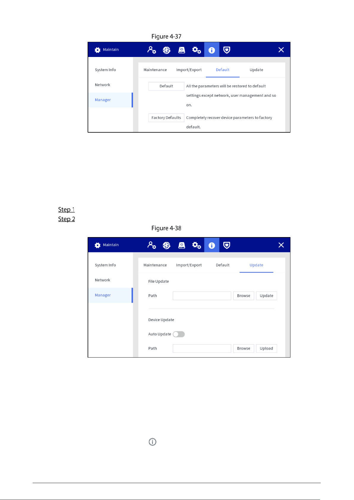
Default
When the system runs slowly and has configuration errors, try to solve the problems by restoring the
default settings.
Tap Factory Defaults, all configurations except the data in the external storage will be deleted. You
can delete data in an external storage by formatting the storage media and other methods.
Select Setting > Maintain > Manager > Default.
Tap Default or Factory Defaults.
39
Default
Default: Tap Default, and the parameters such as except network, user management will
be restored to default setting.
Factory default: Tap Factory Defaults, and the tip dialog is displayed. Tap OK. All
parameters will be restored to the factory default settings.
Station Update
Insert a USB flash drive with update file in bin format, and then import the update file to the Station to
update the system version.
Select Setting > Maintain > Manager > Update.
Select the update file, and then tap Update.
Update
Body Camera Update
Before updating, upload the update files to the Station according to the types of body cameras.
Auto update
Enable the auto update function. The body camera will detect the update files and update
automatically after accessing the Station.
Manual update
When the auto update function is disabled, select the update file, and then tap
Upload to upload
the file of latest version. Tap on the home screen, and then tap the
Update tab to update
the device.
40
4.1.4.6 Security
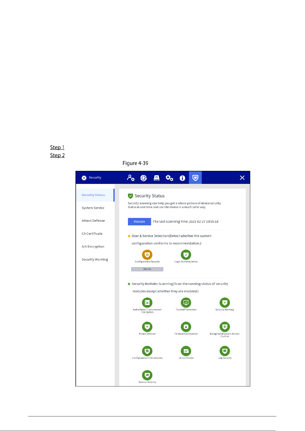
4.1.4.6.1 Security Status
Detect the user and service, and scan the security modules to check the security status of the Station.
When abnormality appears, you can process it timely.
User and service detection: Detect login authentication, user status, and configuration security to
check whether the current configuration conforms to recommendation.
Security modules scanning: Scan the running status of security modules, such as audio/video
transmission, trusted protection, securing warning and attack defense, not detect when they are
enabled.
Procedure
Select Setting > Security > Security Status.
Tap Rescan to scan the security status of the Station.
Security status
41
Results
After scanning, different results will be displayed with different colors. Yellow indicates that the
security modules are abnormal, and Green indicates that the security modules are normal.
Tap
Details to view the details of the scanning result.
Tap Ignore to ignore the exception, and it will not be scanned in next scanning.
Tap Rejoin Detection, and the exception will be scanned in next scanning.
Tap Optimize, and the corresponding screen is displayed, and you can edit the configuration to
clear the exception.
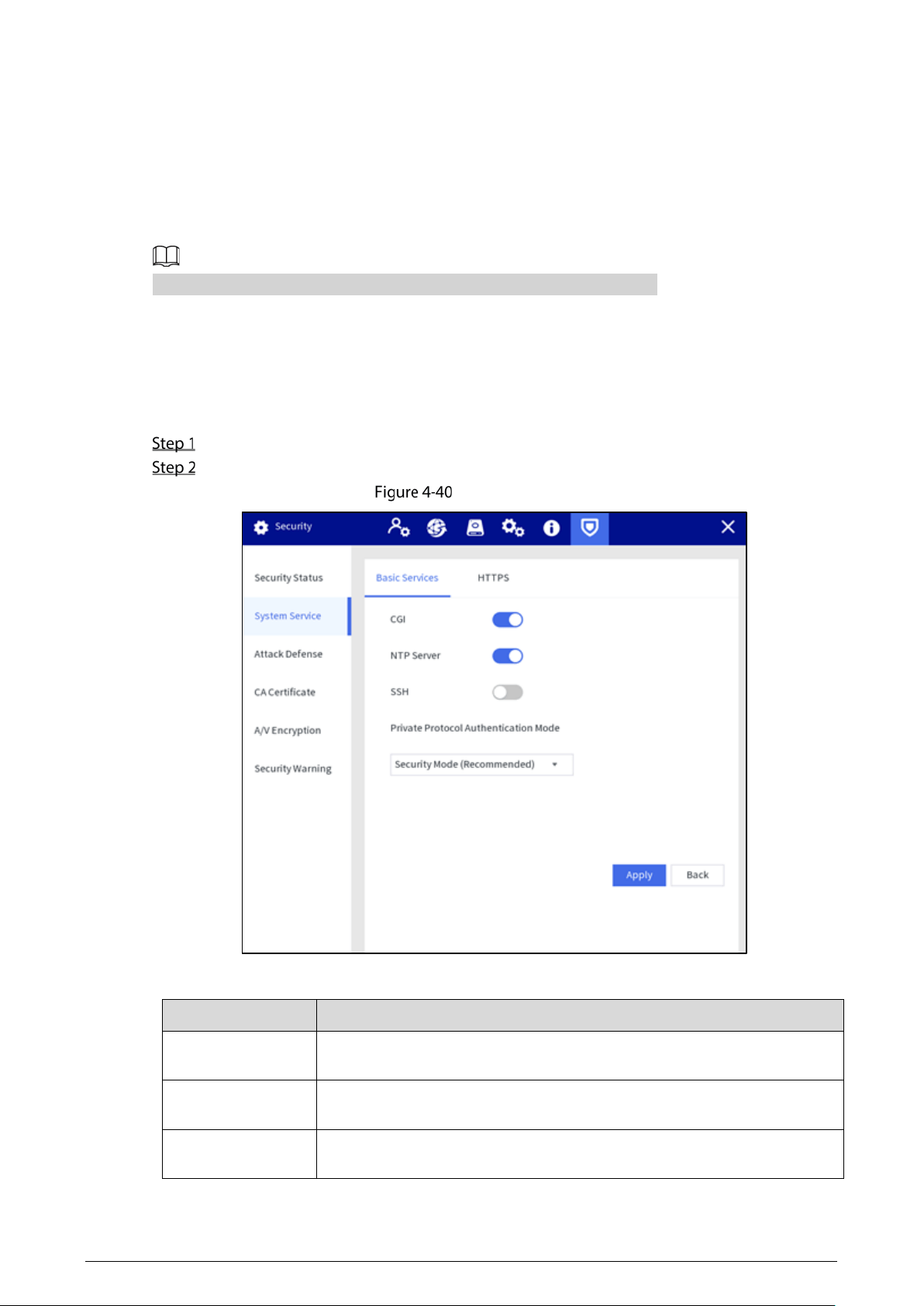
4.1.4.6.2 System
Basic Service
Select Setting > Security > System Service > Basic Services.
Configure parameters.
Basic services
Table 4-7 Basic service parameters description
Parameter
Description
CGI
Enable this function, and then devices can access the Station through this
service. It is enabled by default.
NTP Server
After enabling this function, the Station is used as a NTP server, whic can be
used to synchronize the time of the body camera. It is enabled by default.
SSH
You can enable SSH authentication to realize safety management. It is
enabled by default.
42
Parameter
Description
Private Protocol
Authentication
Mode
Select private protocol authentication mode to guarantee the device
security when login.
Security Mode
is recommended.
Tap Apply.
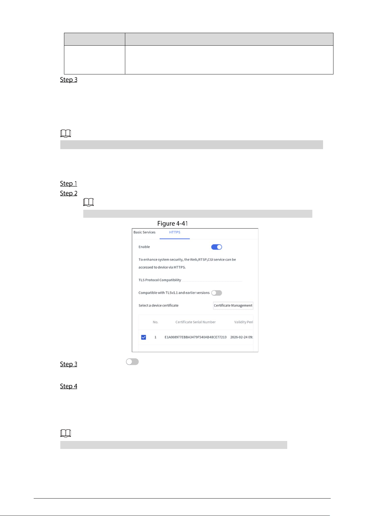
HTTPS
Through creating server certificate, the PC can log in to the device by HTTPS to ensure the security of
communication data and guard the user information and device security with stable technology
measure.
We recommend you to HTTPS service. If the service is disabled, there might be risk of data leakage.
Procedure
Select Setting > Security > Security Center > HTTPS.
Enable HTTPS, and then select the certification.
If there is no certificate in the list, tap Certificate Management to import a certificate.
HTTPS
(Optional) Tap next to Compatible with TLSv1.1 and earlier versions to enable the
protocol compatibility function.
Tap Apply.
Results
Open the browser, enter https://
device IP
:
port
, and then press the Enter key.
Port refers to HTTPS port number. If the HTTPS port is 443, just enter https://device IP.
43
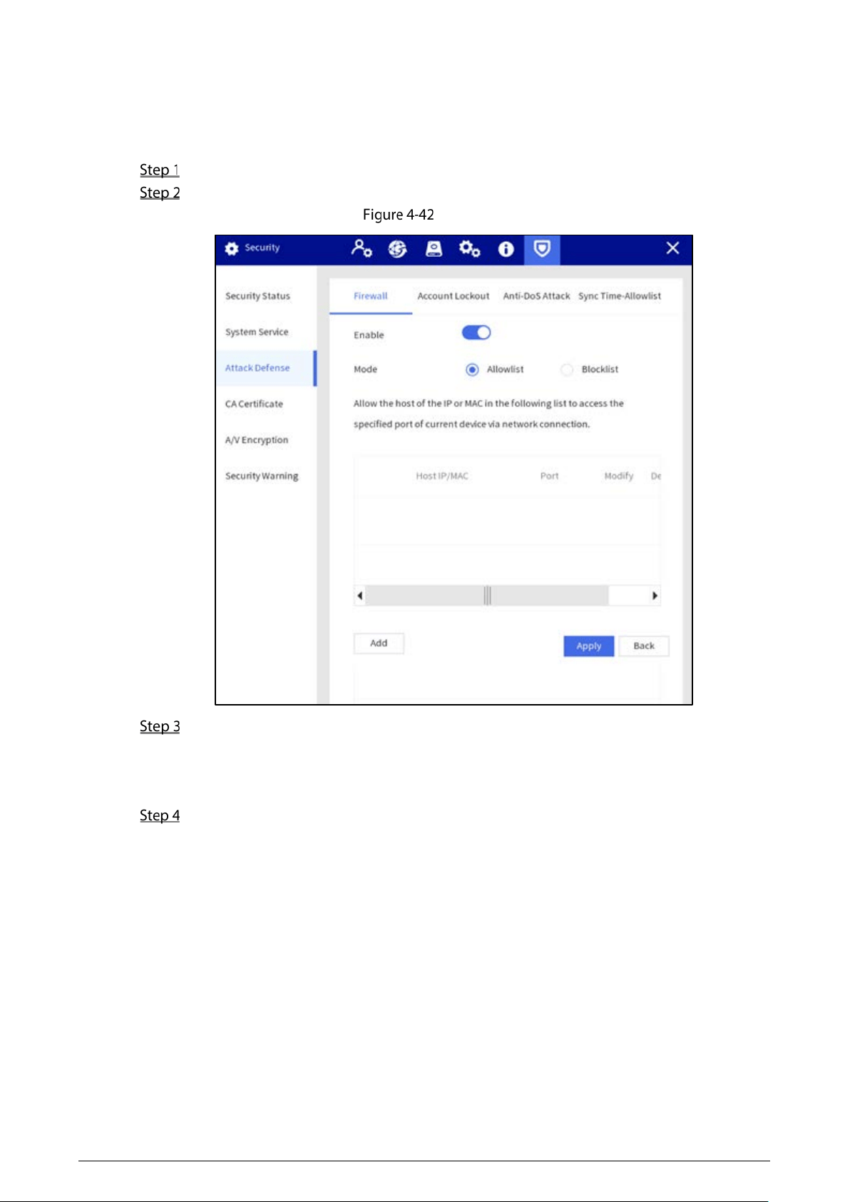
4.1.4.6.3 Attack Defense
Firewall
Configure firewall to limit access to the Station.
Select Setting > Security > Attack Defense > Firewall.
Enable the firewall function.
Firewall
Select the access mode.
Allowlist and Blocklist cannot be enabled at same time.
Allowlist: Only when the IP/MAC of your PC in the allowlist, can you access the Station.
Blocklist: When the IP/MAC of your PC is in the blocklist, you cannot access the Station.
Add the host IP/MAC address to allowlist or blocklist.
1) Tap Add.
2) Enter the information of IP host.
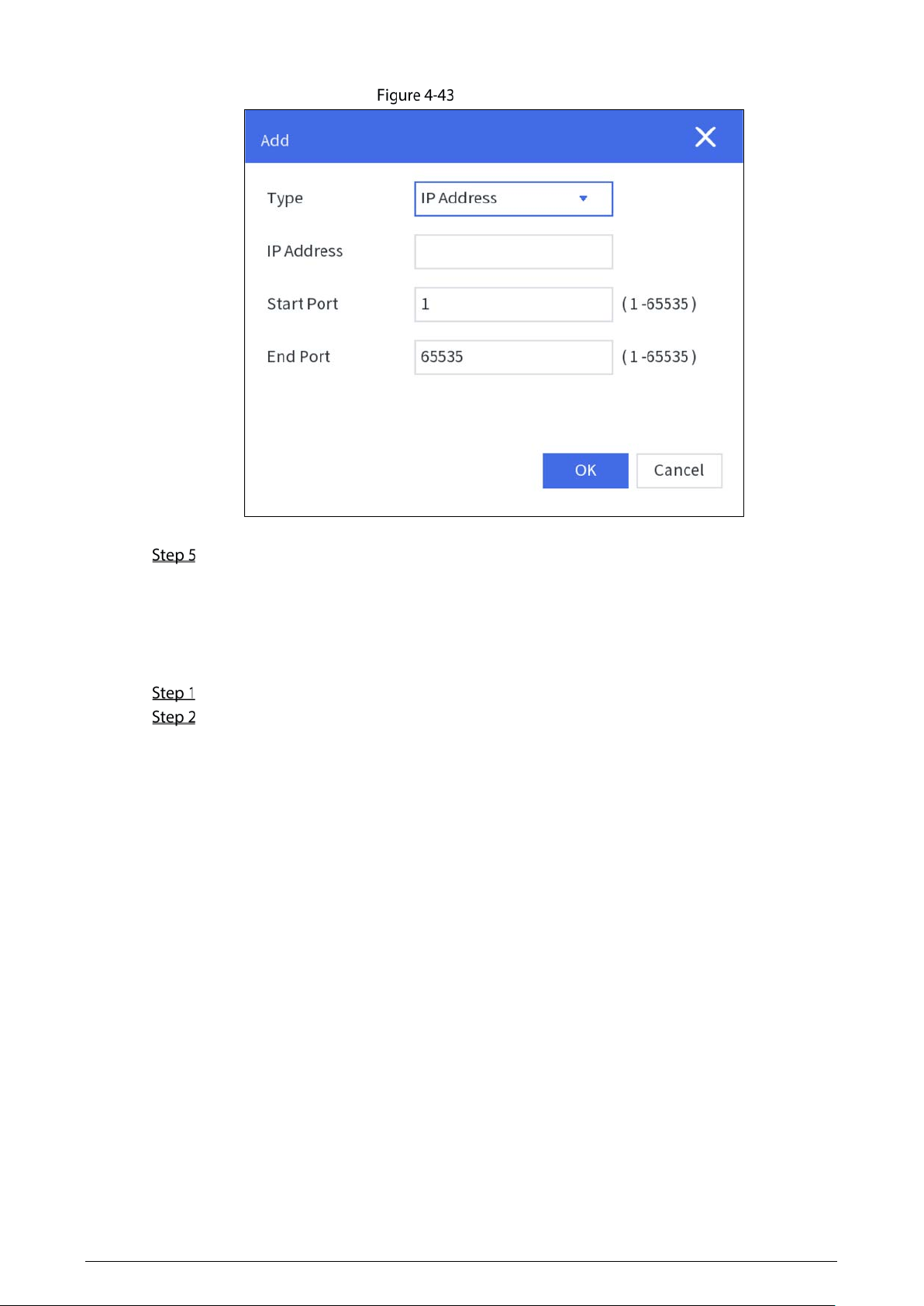
44
Add allowlist
3) Tap
OK.
Tap Apply.
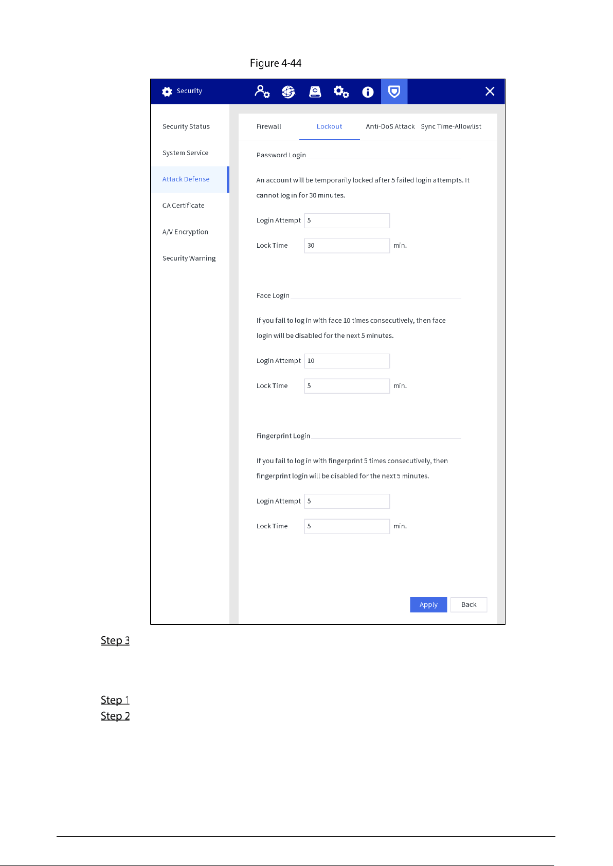
Account Lockout
You can set the number of allowed login attempts and lock time for password login, face login and
fingerprint login. If the number of failed login attempts reaches the defined threshold, the account
will be temporarily locked.
Select Setting > Security > Attack Defense > Lockout.
Configure parameters.
Login Attempt: Upper limit of login attempts. If the number of failed login attempts
reaches the defined threshold, the account will be locked.
Lock Time: The period during which you cannot log in after the number of failed login
attempts reaches upper limit.
45
Account lock
Tap Apply.
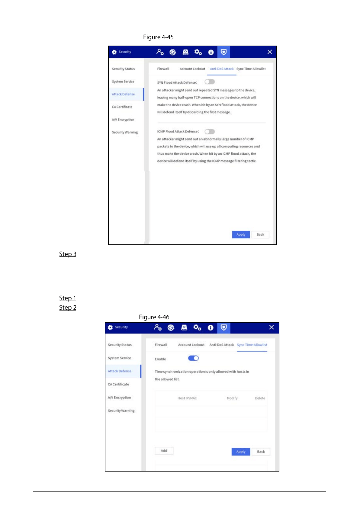
Anti-DoS Attack
Set the attack defense mode to defend the device against Dos (Denial of Service) attack.
Select Setting > Security > Attack Defense > Anti-DoS Attack.
You can enable SYN Flood Attack Defense and ICMP Flood Attack Defense to defend the
device against Dos attack.
46
Anti-DoS attack
Tap Apply.
Sync Time-Allowlist
Set the IP address of hosts that are allowed to sync and change system time, in case that multiple hosts
calibrate the system time with the Station several times.
Select Setting > Security > Attack Defense > Sync Time-Allowlist.
Enable the sync time-allowlist function.
Sync time-allowlist
47
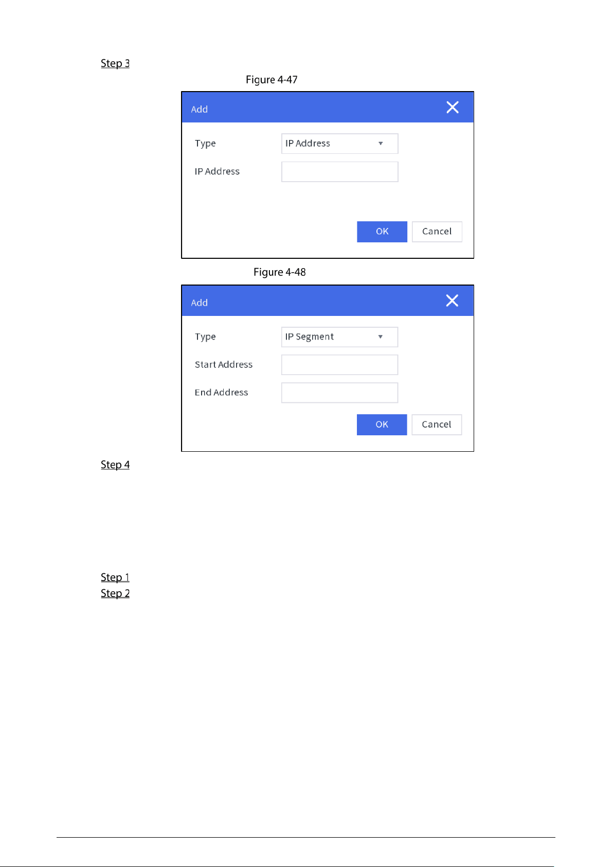
Tap Add to add the IP/MAC of the source host through IP address or IP segment.
Add IP address
IP segment
Tap Apply.
4.1.4.6.4 CA Certificate
Create a certificate or upload an authenticated certificate, and then you can log in through HTTPS with
web browser.
Creating certificate
Select Setting > Security > CA Certificate > Device Certificate.
Tap Create Certificate.
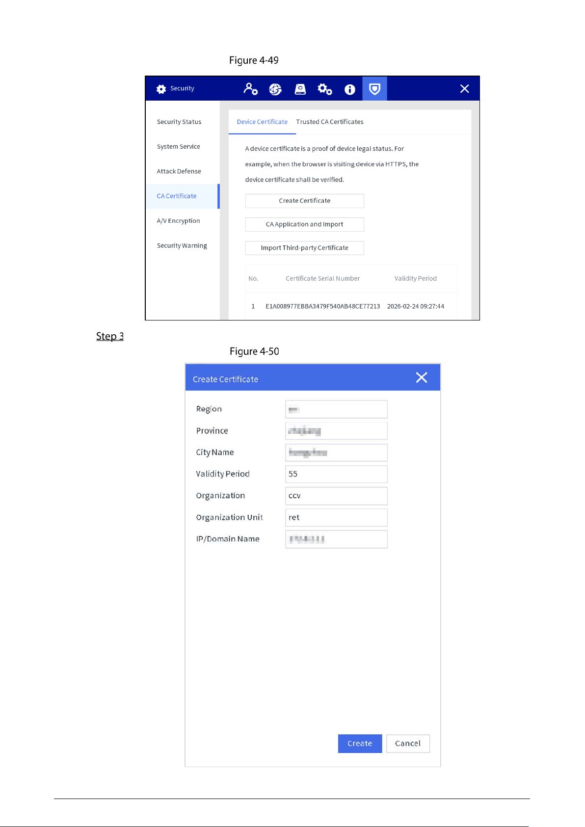
48
Device certificate
Enter the certificate information.
Create certificate
49
Tap Create.
After the certificate is created successfully, you can view the created certificate on the Device
Certificate screen.
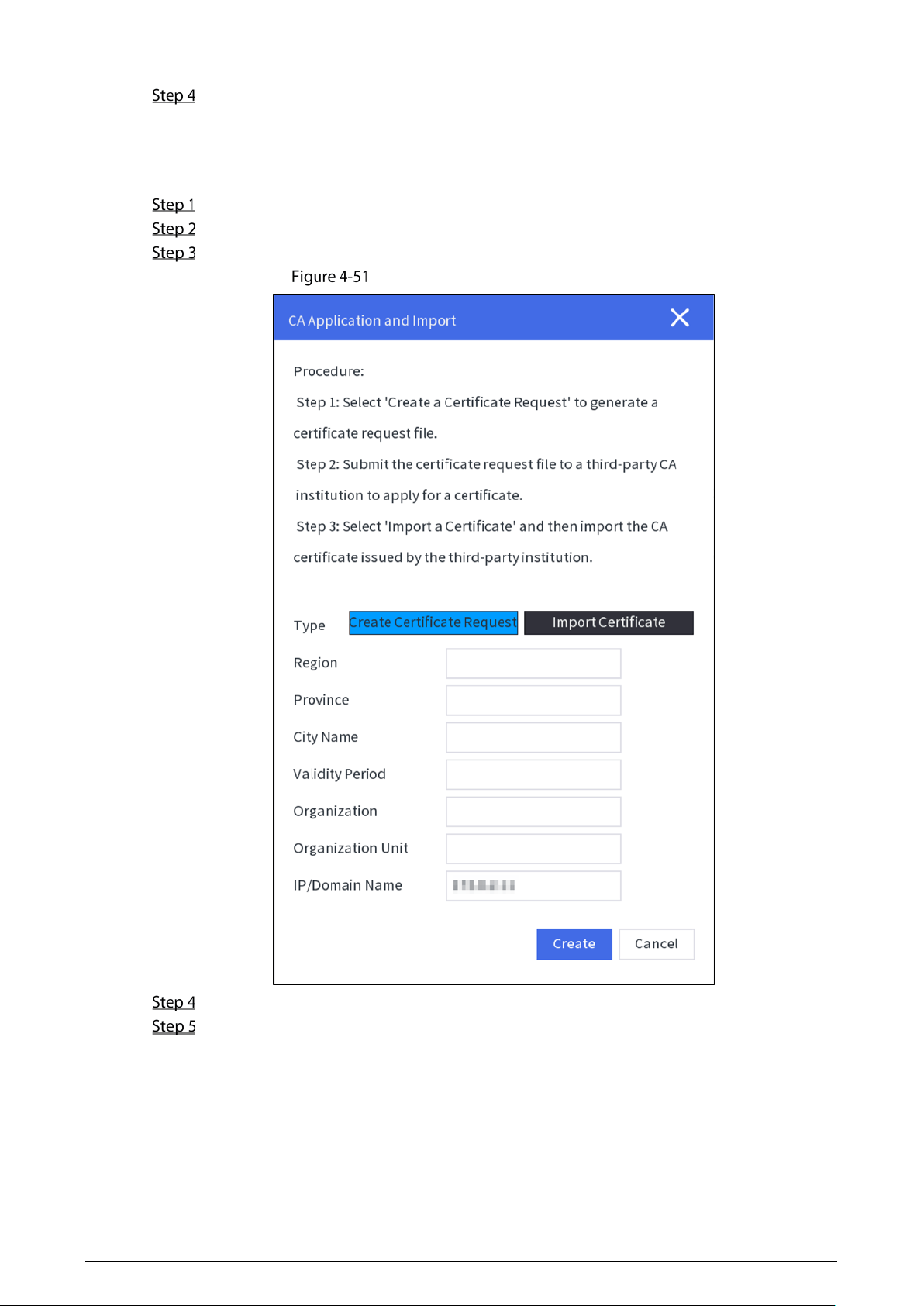
Applying for and Importing CA Certificate
Select Setting > Security > CA Certificate > Device Certificate.
Tap CA Application and Import.
Enter the certificate information, and tap Create to save the certificate to an external device.
Apply for and importing CA certificate
Apply for the CA certificate from the third-party certificate authority.
Import CA certificate.
1) Save the CA certificate to a USB flash drive, and then insert the drive to the Station.
2) Tap
Import Certificate on the CA Application and Import screen.
3) Import the certificate according to the screen instruction.
After the certificate is imported successfully, you can view the created certificate on the
Device Certificate screen.
50
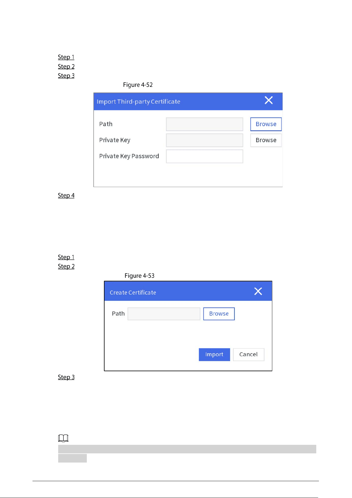
Importing Third-party Certificate
Save the third-party certificate to a USB flash drive, and then insert the drive to the Station.
Select Setting > Security > CA Certificate > Device Certificate.
Tap Import Third-party Certificate.
Select the certificate and private key file, and enter the private key password.
Import third-party certificate
Tap Import.
After the certificate is imported successfully, you can view the created certificate on the
Device Certificate screen.
Installing Trusted CA Certificate
CA certificate is a digital certificate for the legal identity of the Station. For example, when the Station
accesses the LAN through 802.1x, the CA certificate is required.
Select Setting > Security > CA Certificate > Trusted CA Certificate.
Tap Install Trust Certificate.
Install trusted CA certificate
Tap Browse to select the certificate on the prompt screen, and then tap Import.
After the certificate is imported successfully, you can view the created certificate on the
Device Certificate screen.
4.1.4.6.5 A/V Encryption
The Station supports audio and video encryption during data transmission.
We recommended you to enable A/V Encryption function. There might be safety risk if this function
is disabled.
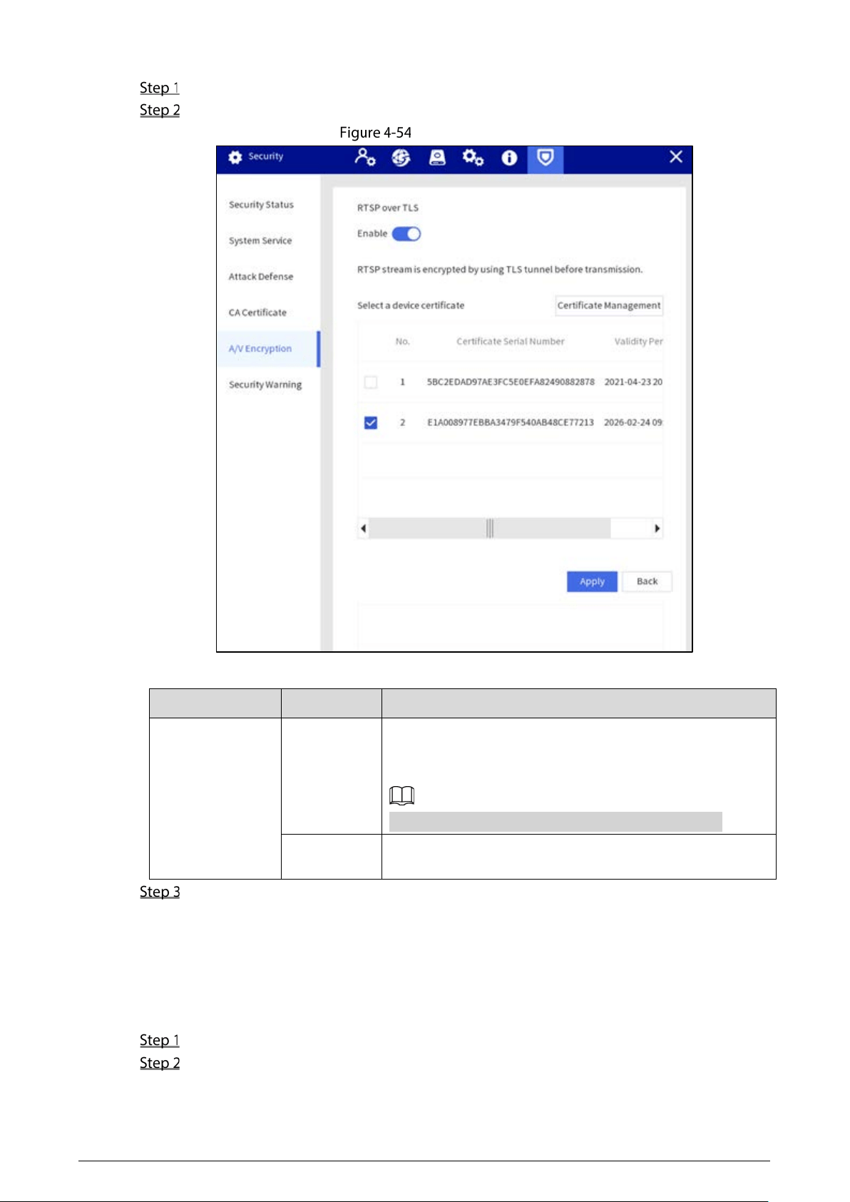
51
Select Setting > Security > A/V Encryption.
Configure parameters.
A/V encryption
Table 4-8 Audio and video description
Encryption Type
Parameter
Description
RTSP over TLS
Enable
Enables RTSP stream encryption by using TLS.
Enable
RTSP over TLS
, and then select certificate in the
Select a device certificate
list.
There might be safety risk if RTSP over TLS is disabled.
Certificate
Management
The created or imported certificate will be displayed in the
Select a device certificate
list, and then select certificate.
Tap Apply.
4.1.4.6.6 Security Warning
Security Exception
Immediately after detecting security abnormal behaviors, the Station sends a security warning to
remind the user timely.
Select Setting > Security > Security Warning > Security Exception.
Enable security warning.
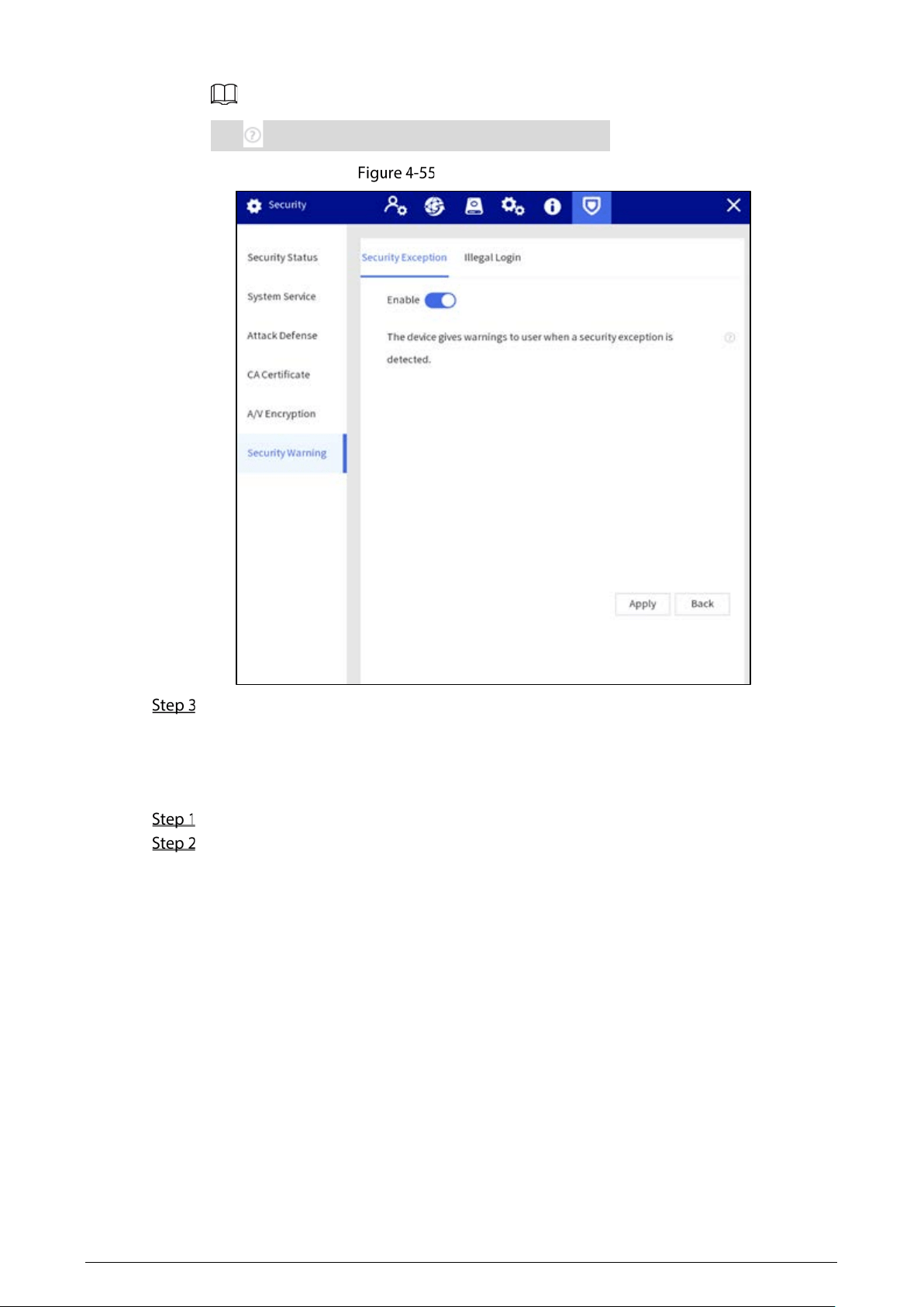
52
Tap to view the details of the security exception event.
Security exception
Tap Apply.
Illegal Login
Immediately after detecting invalid login, the device sends a security warning to remind the user
timely.
Select Setting > Security > Security Warning > Illegal Login.
Enable illegal login warning.
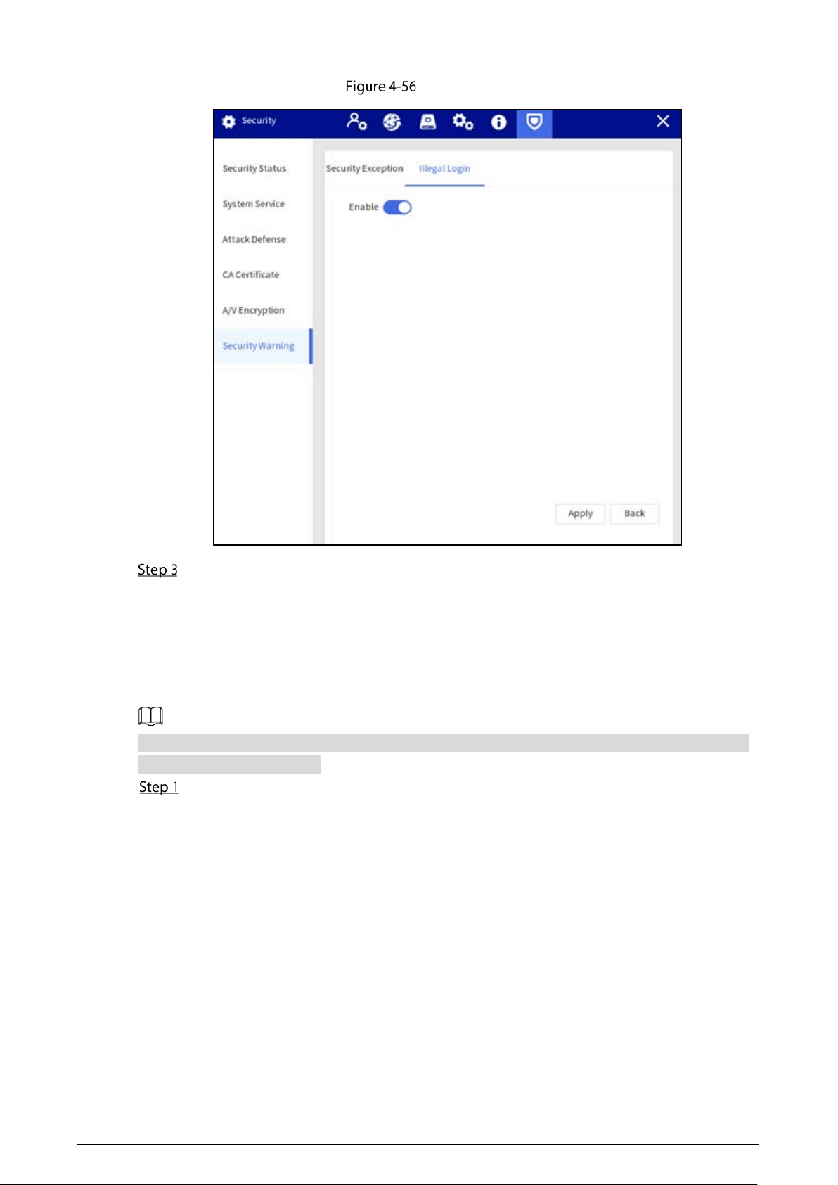
53
Illegal login
Tap Apply.
4.1.5 Platform Configuration
After adding the Station to the platform, you can remotely configure the Station, add devices, and
perform other operations on the platform.
The following operations are for reference only. The actual operation might vary depending on the
actual platform you are using.
Log in to the platform and then on the home page, click Devices.
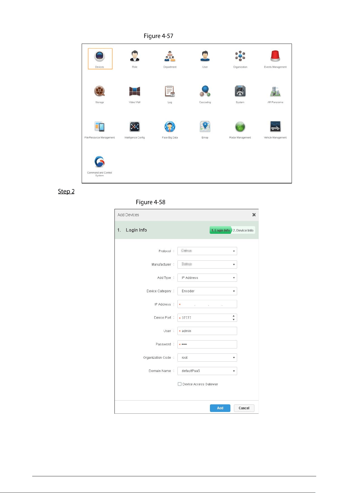
54
Home page
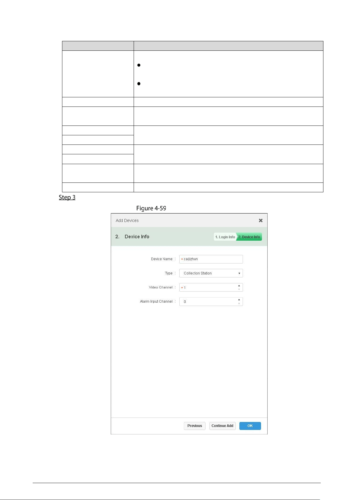
Click Add and then configure the parameters.
Login information
55
Table 4-9 Parameters of adding device
Parameter
Description
Add Type
Two methods are available.
Auto Registration
: The most common method to add devices to
the platform.
IP Address
: Use the IP address of the Station to add it to the
platform.
Device Category Select
Encoder
.
Registration
When the
Add Type
is
Auto Registration
, enter the sub-device ID of
the Station.
IP Address
When the
Add Type
is
IP Address
, enter the IP address and port of the
Station. By default, the port number is 37777.
Device Port
User
Enter the username and password used to log in to the Station.
Password
Organization Code
Select the organization that the Station belongs to. The default
organizatino is root.
Domain Name Select a domain name. The default domain name is defaultPaaS.
Click Add and then configure the device information.
Device information
56
Table 4-10 Device information parameters
Parameter
Description
Device Name Customize a name to identify the Station on the platform.
Type Select
Collection Station
.
Video Channel
Select a video channel for the Station. The default channel is 1。
Alarm Input Channel Select an alarm input channel for the Station. The default channel is 0.
(Optional) Click Continue Add to add more Stations.
Click OK.
Web Configuration
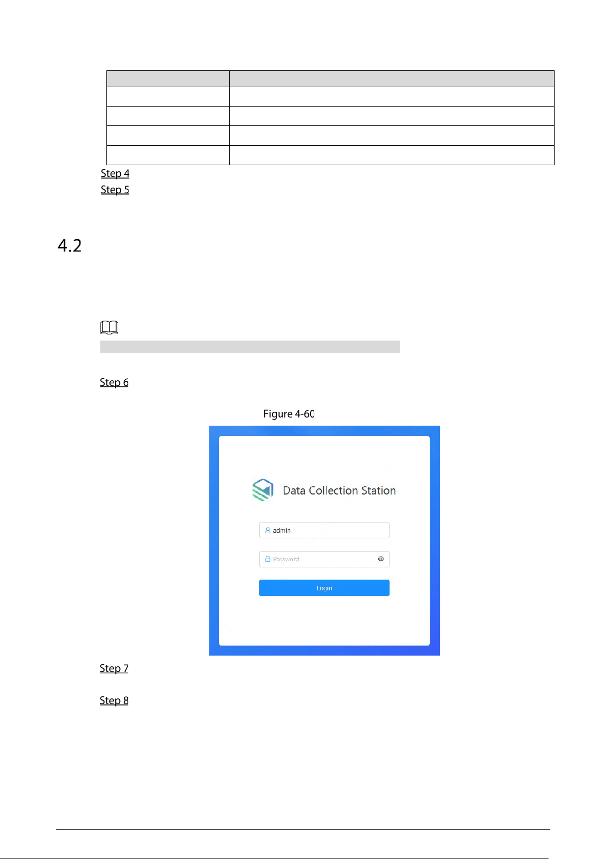
4.2.1 Login
You cannot log in to the Station through browsers without plug-ins.
Log in to the web of the Station as following steps.
Enter the IP address (192.168.1.108 for Ethernet 1 and 192.168.2.108 for Ethernet 2 by default)
in the address bar of the IE browser, and then press Enter.
Login
Enter the username and password.
The administrator account is admin by default.
Tap Login.
57
4.2.2 File Management
4.2.2.1 Collecting Files
After collecting data files from body cameras, the Station will upload the files to the platform or FTP
according to the configuration in
Storage.
Uploading files
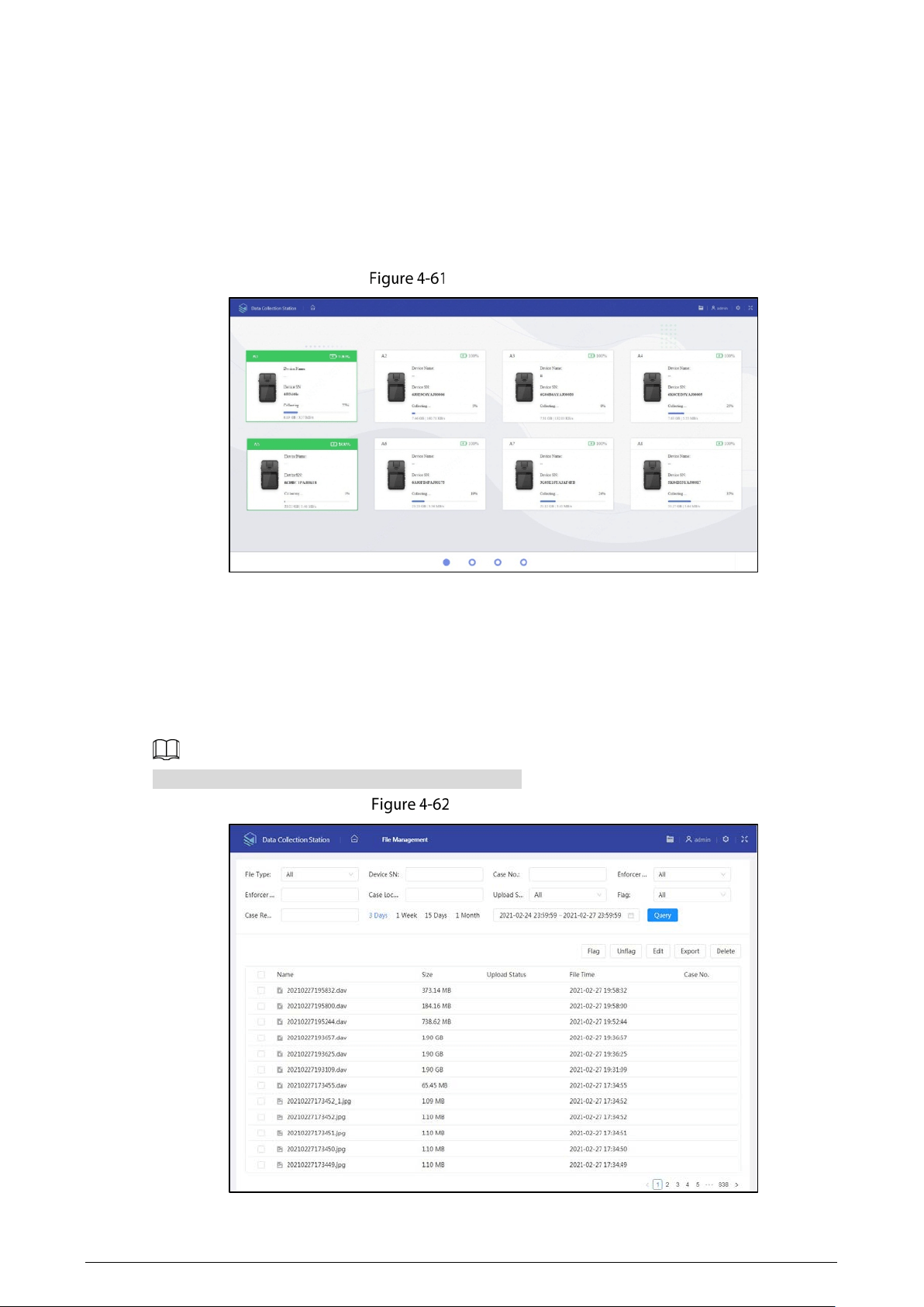
4.2.2.2 Searching for Files
Select File Management, and enter file type, enforcer department, upload status, device SN, enforcer
No, flag, case No., case location, and case remarks, and you can search for video files, audio files and
snapshots according to the configured conditions.
The maximum time range for file searching is 1 month.
Search for files
58
4.2.2.3 Viewing Files
Double-tap a file to view the details, and you can do the operations of fast play, slow play, zoom in or
zoom out.
You cannot fast play or slow play an audio file in AMR format.
4.2.3 Configuring Web
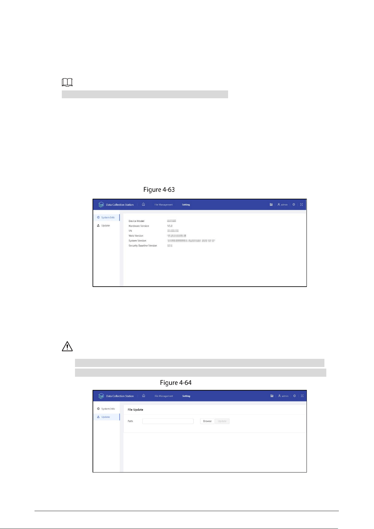
4.2.3.1 System Information
Select Setting > System Info, and you can view device model, hardware version, SN, web version,
system version and security baseline version.
System information
4.2.3.2 Update
Select Setting > Update, select the file, and then tap Update.
Do not disconnect the power or network, or restart or shutdown the Station during update.
Make sure that the upgrade file is correct. Improper upgrade file might result in device error.
Update

59
RAID
RAID is an abbreviation for Redundant Array of Independent Disks. It is to combine several
independent HDDs (physical HDD) to form an HDD group (logic HDD), to provide higher storage
performance and data redundancy.
RAID Level
Comparing with one HDD, RAID provides more storage capacity and data redundancy. The different
redundant arrays have different RAID level. Each RAID level has its own data protection, data
availability and performance degree.
RAID Level
Description
Min. HDD Needed
RAID 0
RAID 0 is so called striping.
RAID 0 is to save the continued data fragmentation on
several HDDs. It can process the read and write at the same
time, so its read/write speed is N (N refers to the HDD
amount of the RAID 0) times as many as one HDD. RAID 0
does not have data redundant, so one HDD damage might
result in data loss that cannot be restored.
2
RAID 1
It is also called mirror or mirroring.
RAID 1 data is written to two or multiple HDDs equally,
which guarantees the system reliability, and the data can
be repaired. RAID 1 read speed is almost close to the total
volume of all HDDs. The write speed is limited by the
slowest HDD. At the same time, the RAID 1 has the lowest
HDD usage rate. It is only 50%.
RAID 5
RAID 5 is to save the data and the corresponding odd/even
verification information to each HDD of the RAID 5 group
and save the verification information and corresponding
data to different HDDs. When one HDD of the RAID 5 is
damaged, system can use the rest data and corresponding
verification information to restore the damaged data. It
does not affect data integrity.
3
RAID 6
Based on the RAID 5, RAID 6 adds one odd/even verification
HDD. The two independent odd/even systems adopt
different algorithms, the data reliability is very high. Even
two HDDs are broken at the same time, there is no data loss
risk. Comparing to RAID 5, the RAID 6 needs to allocate
larger HDD space for odd/even verification information, so
its read/write is even worse.
4
RAID 10
RAID 10 is a combination of the RAID 1 and RAID 0. It uses
the extra high speed efficient of the RAID 0 and high data
protection and restores capability of the RAID 1. It has high
read/write performance and security. However, the RAID 10
HDD usage efficiency is as low as RAID 1.
RAID Capacity
Refer to the sheet for RAID space information.

60
capacityN refers to the mini HDD amount to create the corresponding RAID, which is subject to the
value on the web page.
Parameter
Total Space of the N HDD
RAID 10 (N/2) × min (capacityN)
RAID 6 (N-2) × min (capacityN)
RAID 5 (N-1) × min (capacityN)
RAID 1 Min (capacityN)
RAID 0 The total amount of current RAID group

61
Cybersecurity Recommendations
Mandatory actions to be taken for basic device network security:
1. Use Strong Passwords
Please refer to the following suggestions to set passwords:
The length should not be less than 8 characters.
Include at least two types of characters; character types include upper and lower case
letters, numbers and symbols.
Do not contain the account name or the account name in reverse order.
Do not use continuous characters, such as 123, abc, etc.
Do not use overlapped characters, such as 111, aaa, etc.
2. Update Firmware and Client Software in Time
According to the standard procedure in Tech-industry, we recommend to keep your device
(such as NVR, DVR, IP camera, etc.) firmware up-to-date to ensure the system is equipped
with the latest security patches and fixes. When the device is connected to the public
network, it is recommended to enable the “auto-check for updates” function to obtain
timely information of firmware updates released by the manufacturer.
We suggest that you download and use the latest version of client software.
"Nice to have" recommendations to improve your device network security:
1. Physical Protection
We suggest that you perform physical protection to device, especially storage devices. For
example, place the device in a special computer room and cabinet, and implement well-done
access control permission and key management to prevent unauthorized personnel from
carrying out physical contacts such as damaging hardware, unauthorized connection of
removable device (such as USB flash disk, serial port), etc.
2. Change Passwords Regularly
We suggest that you change passwords regularly to reduce the risk of being guessed or cracked.
3. Set and Update Passwords Reset Information Timely
The device supports password reset function. Please set up related information for password
reset in time, including the end user’s mailbox and password protection questions. If the
information changes, please modify it in time. When setting password protection questions, it is
suggested not to use those that can be easily guessed.
4. Enable Account Lock
The account lock feature is enabled by default, and we recommend you to keep it on to guarantee
the account security. If an attacker attempts to log in with the wrong password several times, the
corresponding account and the source IP address will be locked.
5. Change Default HTTP and Other Service Ports
We suggest you to change default HTTP and other service ports into any set of numbers between
1024–65535, reducing the risk of outsiders being able to guess which ports you are using.
6. Enable HTTPS
We suggest you to enable HTTPS, so that you visit Web service through a secure communication
channel.
7. MAC Address Binding
We recommend you to bind the IP and MAC address of the gateway to the device, thus reducing

62
the risk of ARP spoofing.
8. Assign Accounts and Privileges Reasonably
According to business and management requirements, reasonably add users and assign a
minimum set of permissions to them.
9. Disable Unnecessary Services and Choose Secure Modes
If not needed, it is recommended to turn off some services such as SNMP, SMTP, UPnP, etc., to
reduce risks.
If necessary, it is highly recommended that you use safe modes, including but not limited to the
following services:
SNMP: Choose SNMP v3, and set up strong encryption passwords and authentication
passwords.
SMTP: Choose TLS to access mailbox server.
FTP: Choose SFTP, and set up strong passwords.
AP hotspot: Choose WPA2-PSK encryption mode, and set up strong passwords.
10. Audio and Video Encrypted Transmission
If your audio and video data contents are very important or sensitive, we recommend that you
use encrypted transmission function, to reduce the risk of audio and video data being stolen
during transmission.
Reminder: encrypted transmission will cause some loss in transmission efficiency.
11. Secure Auditing
Check online users: we suggest that you check online users regularly to see if the device is
logged in without authorization.
Check device log: By viewing the logs, you can know the IP addresses that were used to log
in to your devices and their key operations.
12. Network Log
Due to the limited storage capacity of the device, the stored log is limited. If you need to save the
log for a long time, it is recommended that you enable the network log function to ensure that
the critical logs are synchronized to the network log server for tracing.
13. Construct a Safe Network Environment
In order to better ensure the safety of device and reduce potential cyber risks, we recommend:
Disable the port mapping function of the router to avoid direct access to the intranet devices
from external network.
The network should be partitioned and isolated according to the actual network needs. If
there are no communication requirements between two sub networks, it is suggested to use
VLAN, network GAP and other technologies to partition the network, so as to achieve the
network isolation effect.
Establish the 802.1x access authentication system to reduce the risk of unauthorized access
to private networks.
Enable IP/MAC address filtering function to limit the range of hosts allowed to access the
device.