Models
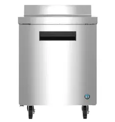
Upright A-Series
Steelheart Series
Refrigerated Kitchen Equipment
Service Manual
Number: 73237
Issued: 2-25-2019
Revised: 3-24-2022
hoshizakiamerica.com

2
WARNING
Only qualied service technicians should install and service the appliance. To
obtain the name and phone number of your local Hoshizaki Certied Service
Representative, visit www.hoshizaki.com. No service should be undertaken until
the technician has thoroughly read this Service Manual. Failure to service and
maintain the appliance in accordance with this manual will adversely affect safety,
performance, component life, and warranty coverage. Proper installation is the
responsibility of the installer. Product failure or property damage due to improper
installation is not covered under warranty.
Hoshizaki provides this manual primarily to assist qualied service technicians in the
service and maintenance of the appliance.
Should the reader have any questions or concerns which have not been satisfactorily
addressed, please call, send an e-mail message, or write to the Hoshizaki Technical
Support Department for assistance.
Phone: 1-800-233-1940; (770) 487-2331
Fax: 1-800-843-1056; (770) 487-3360
E-mail: techsuppor[email protected]
618 Highway 74 South
Peachtree City, GA 30269
Attn: Hoshizaki Technical Support Department
Web Site: www.hoshizaki.com
NOTE: To expedite assistance, all correspondence/communication MUST include the
following information:
• Model Number
• Serial Number
• Complete and detailed explanation of the problem.

3
IMPORTANT
This manual should be read carefully before the appliance is serviced. Read
the warnings and guidelines contained in this manual carefully as they provide
essential information for the continued safe use, service, and maintenance of the
appliance. Retain this manual for any further reference that may be necessary.
CONTENTS
Important Safety Information ................................................................................................. 5
I. General Information ............................................................................................................ 8
A. Construction .................................................................................................................. 8
B. Refrigeration Flow Chart ............................................................................................. 10
II. Sequence of Operation and Service Diagnosis ................................................................11
A. Sequence of Operation Flow Charts ............................................................................11
1. Refrigerator .............................................................................................................11
2. Freezer .................................................................................................................. 12
B. Service Diagnosis ....................................................................................................... 13
1. Refrigerator ............................................................................................................ 15
2. Freezer .................................................................................................................. 19
C. Control Module Check ................................................................................................. 23
D. Thermistor Check ........................................................................................................ 24
E. Diagnostic Tables ........................................................................................................ 25
III. Controls and Adjustments ............................................................................................... 27
A. Control Module ............................................................................................................ 27
B. Temperature ............................................................................................................... 29
1. Default Settings ...................................................................................................... 29
2. Temperature Setpoint ............................................................................................ 29
3. Changing the Temperature Display Scale (°F or °C) ............................................. 29
C. Defrost ........................................................................................................................ 30
D. Alarm Safeties ............................................................................................................. 31
E. Safety Devices and Light Control ................................................................................ 32
F. Mullion/Perimeter Heater ............................................................................................. 32
IV. Refrigeration Circuit and Component Service Information.............................................. 33
A. Service for Refrigerant Lines ....................................................................................... 35
B. Component Service Information .................................................................................. 38
C. Door Reversal ............................................................................................................. 38
V. Maintenance .................................................................................................................... 39
VI. Preparing the Appliance for Periods of Non-Use ............................................................ 40
VII. Disposal ......................................................................................................................... 41

4
VIII. Technical Information .................................................................................................... 42
A. Electrical and Refrigerant Data ................................................................................... 42
B. Wiring Diagrams .......................................................................................................... 43
1. R1A/R2A/F1A-FG/FGCL/FGCR/FS/FSJ/FSL/FSLJ/HG/HS/HSL, ........................ 43
PT1A-FG-FG/FS-FS/HS-HS ................................................................................. 43
2. RN1A-FS, RT1A-FS-FS ......................................................................................... 44
3. RN2A-FS, RT2A-FS-FS ........................................................................................ 45
4. PT2A-FG-FG/FS-FS/HS-HS .................................................................................. 46
5. R3A-FG/FGCL/FGCR/FS/FSCL/FSCR/HS/HG .................................................... 47
6. F2A-FG/FS/HG/HS .............................................................................................. 48
7. F3A-FS/HS ............................................................................................................. 49
8. DT1A-HS ............................................................................................................... 50
9. DT2A-FS/HS .......................................................................................................... 51

5
DANGER
Risk of Fire or Explosion
Flammable Refrigerant Used
• Follow handling instructions carefully
in compliance with U.S. government
regulations.
• Do not use mechanical devices to defrost.
• Do not puncture refrigerant tubing. Risk
of re or explosion due to puncture
of refrigerant tubing; follow handling
instructions carefully.
• Component parts shall be replaced with
like components.
• Servicing shall be done by factory
authorized service personnel to minimize
the risk of possible ignition due to incorrect
parts or improper service.
• Consult instruction manual/ service
manual before attempting to install or
service this product. All safety precautions
must be followed.
• Dispose of properly in accordance with
federal or local regulations.
• Do not place any potential ignition sources
in or near the appliance.
Important Safety Information
Throughout this manual, notices appear to bring your attention to situations which could
result in death, serious injury, damage to the appliance, or damage to property.
DANGER
Indicates a hazardous situation that, if not avoided, will result in
death or serious injury.
WARNING
Indicates a hazardous situation that, if not avoided, could result
in death or serious injury.
NOTICE
Indicates a situation that, if not avoided, could result in damage
to the appliance or property.
IMPORTANT
Indicates important information about the use and care of the
appliance.
Risque De Feu Ou D'Explosion
Le Frigorigène Est Inammable
• Suivre attentivement les instructions
de manipulation conformément à la
réglementation gouvernementale.
• Ne pas utiliser d'appareils mécaniques
pour dégivrer le réfrigérateur.
• Ne pas perforer la tubulure contenant le
frigorigène. Risque de feu ou d'explosion
si la tubulure contenant le frigorigène
est perforée; suivre les instructions de
manutention avec soin.
• Les pièces des composants doivent être
remplacées par des pièces et accessoires
équivalents.
• L’entretien doit être effectué par le
personnel de service autorisé par le
fabricant an de minimiser les risques
d’inammation attribuables à l’installation
d’une pièce inadéquate ou à la mauvaise
exécution du service.
• Consulter le manuel du propriétaire/
guide de réparation avant de tenter une
réparation. Toutes les mesures de sécurité
doivent être respectées.
• Éliminer conformément aux règlements
fédéraux ou locaux.
• Ne placez aucune source d’inammation
potentielle dans ou près de l’appareil.

6
WARNING
The appliance should be destined only to
the use for which it has been expressly
conceived. Any other use should be
considered improper and therefore
dangerous. The manufacturer cannot be
held responsible for injury or damage
resulting from improper, incorrect, and
unreasonable use. Failure to install,
operate, and maintain the appliance
in accordance with this manual will
adversely affect safety, performance,
component life, and warranty coverage.
To reduce the risk of death, electric
shock, serious injury, or re, follow
basic precautions including the
following:
• Only qualied service technicians should
install and service the appliance.
• Wear appropriate personal protective
equipment (PPE) when servicing the
appliance.
• The appliance must be installed in
accordance with applicable national, state,
and local codes and regulations.
• Appliance is heavy. Use care when lifting
or positioning. Work in pairs when needed
to prevent injury or damage. Do not lift
using the top section or the doors/drawers.
• To reduce the risk of electric shock, do not
touch the plug with damp hands.
• Unplug the appliance before servicing.
• The appliance requires an independent
power supply of proper capacity. See the
nameplate for electrical specications.
Failure to use an independent power
supply of proper capacity can result in a
tripped breaker, blown fuse, damage to
existing wiring, or component failure. This
could lead to heat generation or re.
• THE APPLIANCE MUST BE
GROUNDED. The appliance is equipped
with a NEMA5-15 three-prong grounding
plug to reduce the risk of potential
shock hazards. It must be plugged into a
properly grounded, independent 3-prong
wall outlet. If the outlet is a 2-prong outlet,
it is your personal responsibility to have
a qualied electrician replace it with a
properly grounded, independent 3-prong
wall outlet. Do not remove the ground
prong from the power cord and do not use
an adapter plug. Failure to follow these
instructions may result in death, electric
shock, or re.
• Do not use an extension cord.
• Do not use an appliance with a damaged
power cord. The power cord should not be
altered, jerked, bundled, weighed down,
pinched, or tangled. Such actions could
result in electric shock or re. To unplug
the appliance, be sure to pull the plug, not
the cord, and do not jerk the cord.
• The GREEN ground wire in the factory-
installed power cord is connected to the
appliance. If it becomes necessary to
remove or replace the power cord, be
sure to connect the power cord's ground
wire.
• Do not splash, pour, or spray water
directly onto or into the appliance. This
might cause short circuit, electric shock,
corrosion, or failure.
• Do not make any alterations to the
appliance. Alterations could result in
electric shock, injury, re, or damage to
the appliance.
• The appliance is not intended for use by
persons (including children) with reduced
physical, sensory, or mental capabilities,
or lack of experience and knowledge,
unless they have been given supervision
or instruction concerning use of the
appliance by a person responsible for
their safety.

7
WARNING, continued
• Do not put warm or hot foods in the cabinet.
Let them cool rst, or they will raise the
cabinet temperature and could deteriorate
other foods in the cabinet or overload the
appliance.
• Food storage and handling must comply with
applicable codes and regulations.
• All foods should be wrapped in plastic lm
or stored in sealed containers. Otherwise
foods may dry up, pass their smells onto
other foods, cause frost to develop, result in
poor appliance performance, or increase the
likelihood of cross-contamination. Certain
dressings and food ingredients, if not
stored in sealed containers, may accelerate
corrosion of the evaporator, resulting in
failure.
• Do not store items near air outlets.
Otherwise, items may freeze up and
crack or break causing a risk of injury or
contamination of other food.
NOTICE
• Protect the oor when moving the appliance
to prevent damage to the oor.
• Keep ventilation openings, in the appliance
enclosure or in the built-in structure, clear of
obstruction.
• Do not allow the appliance to bear any
outside weight.
• To prevent deformation or cracks, do not
spray insecticide onto the plastic parts or let
them come into contact with oil.
• To avoid damage to the gasket, use only the
door handle when opening and closing.
WARNING, continued
• Children should be properly supervised
around the appliance.
• Do not climb, stand, or hang on the
appliance or doors or allow children or
animals to do so. Do not climb into the
appliance or allow children or animals to
do so. Death or serious injury could occur
or the appliance could be damaged.
• Be careful not to pinch ngers when
opening and closing the doors or when
handling food pans. Be careful when
opening and closing the doors when
children are in the area.
• Open and close the doors with care.
Opening the doors too quickly or forcefully
may cause injury or damage to the
appliance or surrounding equipment.
• Do not use combustible spray or place
volatile or ammable substances in or
near the appliance. They might catch re.
• Keep the area around the appliance clean.
Dirt, dust, or insects in the appliance
could cause harm to individuals or
damage to the equipment.
• Do not throw anything onto the shelves
or load any single shelf with more than
120lb. (54.5 kg) of product. They might fall
off and cause injury.
• The appliance is designed only for
temporary storage of food. Employ
sanitary methods. Use for any other
purposes (for example, storage of
chemicals or medical supplies such
as vaccine and serum) could cause
deterioration of stored items.
• Do not place any product on the oor of
the cabinet. All product must be placed on
properly installed shelves.
• Do not block air inlets or outlets, otherwise
cooling performance may be reduced.
• Do not tightly pack the cabinet. Allow
some space between items to ensure
good air ow. Also allow space between
items and interior surfaces.

8
I. General Information
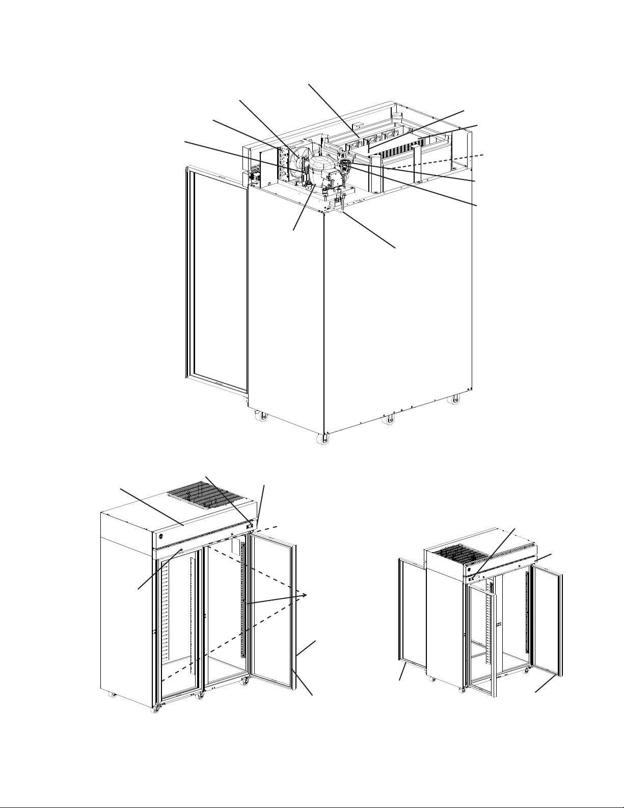
A. Construction
1. Solid Door Models
Condenser Fan Motor
Condenser
Control Module
Front Panel
Door
Door
Gasket
Door Lock
Model Shown: R1A-FS
Light
Compressor
Power Cord
Door Switch
Thermostatic
Expansion Valve
Defrost Thermistor
Evaporator
Cabinet
Thermistor
Wick
Control Panel
Evaporator Fan Motor
Model Shown: PT1A-FS-FS
Control Module
Control
Panel
Door
Door
Gasket
Door
9
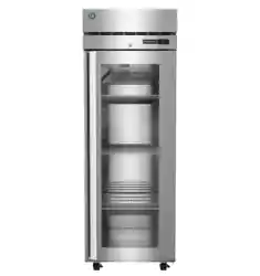
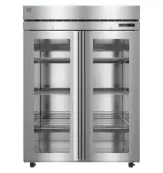
2. Glass Door Models
Condenser Fan Motor
Condenser
Control Module
Door
Door
Gasket
Model Shown: R2A-FG
Compressor
Power Cord
Thermostatic
Expansion Valve
LED Lights
Glass Door
Models
Model Shown: R2A-FG
24VDC Driver
Glass Door
Models
Control Panel
Front Panel
Wick
Defrost Thermistor
Evaporator
Cabinet
Thermistor
Evaporator Fan Motor
Door Lock
Model Shown: PT2A-FG-FG
Control Module
Control
Panel
Door
Gasket
Door
Thermostatic
Expansion Valve
Heater

10
Evaporator Fans
(quantity depends on model)
Evaporator
Thermostatic Expansion Valve
Compressor
Condensate Pan
High-Pressure Switch
Drier
Condenser Fan
Condenser
Defrost
Thermistor
Defrost Heater and
Defrost Thermostat
(Freezer only)
Cabinet Thermistor
B. Refrigeration Flow Chart
Thermostatic Expansion
Valve Heater
2-Section Models Only

11
II. Sequence of Operation and Service Diagnosis
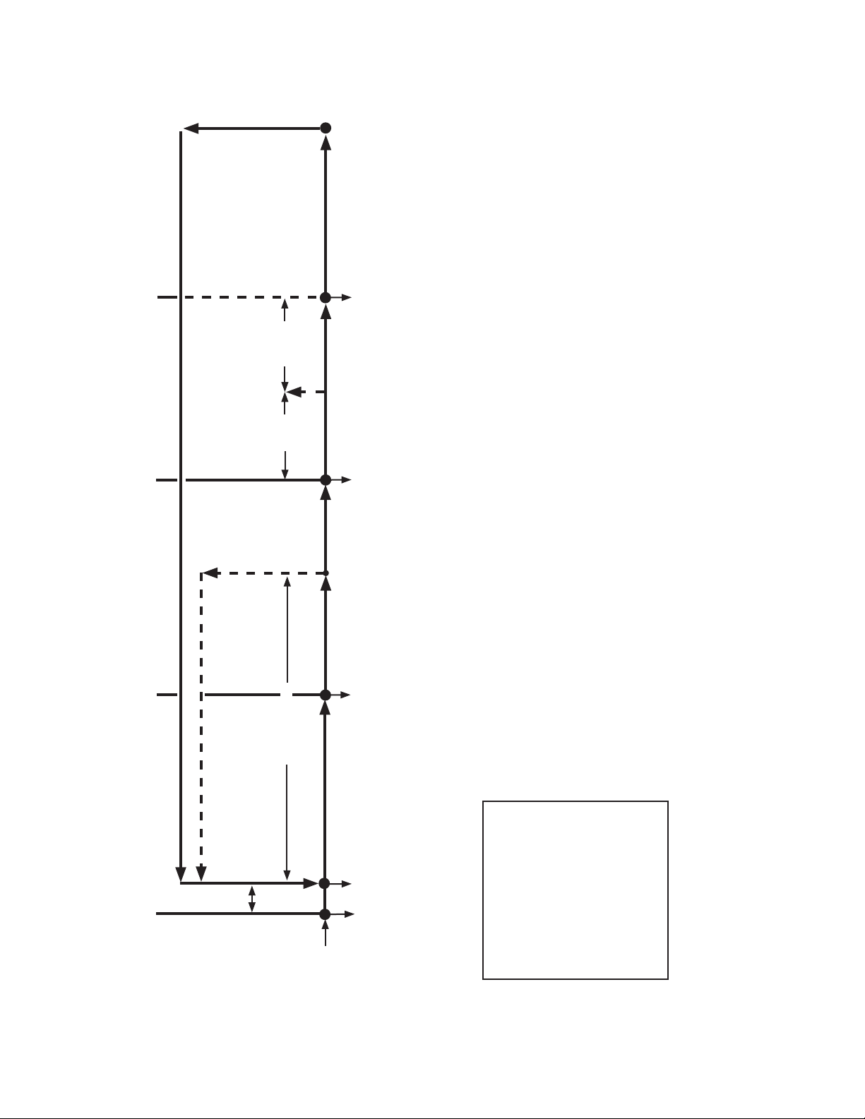
A. Sequence of Operation Flow Charts
1. Refrigerator
3. Cool Down Restart
1. Startup/Cool Down
2. Cool Down Achieved
CTh in control
Slight
Delay at
Startup
CTh cools to
3°F (1.7°C)
below setpoint.
Factory default
38°F (3°C)
CTh warms
to 3°F (1.7°C)
above setpoint
4. Defrost
5. Defrost Termination
Note:
a) EvapFM delays energizing if DTh above 50°F (10°C).
b) EvapFM de-energizes when door is opened on -FS models and when upper door is opened
on -HS models.
c) 2-min. minimum Comp on timer starts when Comp energizes.
d) 2-min. minimum Comp off timer starts when Comp de-energizes.
e) 5-min. minimum defrost time.
f) 1-hr. maximum defrost time.
g) "dEF" displayed during defrost.
h) 15-minute temperature delay timer starts when Comp/ConFM energize.
i) MH and BH de-energizes when Comp and CondFM de-energize on PT2A, RN2A, and RT2A models.
Power on
2-min. Comp off
timer starts
2-min. Comp on
timer starts
2-hr cumulative compressor run or
2-hr continuous compressor run
defrost timer terminates
Legend:
BH-bottom heater
Comp-compressor
ConFM-condenser fan motor
CTh-cabinet thermistor
DTh-defrost thermistor
EvapFM-evaporator fan motor
MH-mullion heater
TXVH-thermostatic expansion
valve heater
5-min.
minimum
defrost
DTh in control
DTh warms to
44°F (6.6°C) or
1-hr maximum
defrost timer
terminates
Comp energized
ConFM energized
EvapFM energized
MH/BH energized
(PT2A, R_2A)
Comp de-energized
ConFM de-energized
MH de-energized (PT2A, R_2A)
EvapFM de-energized
(60-sec. delay
before de-energized)
EvapFM energized
Comp de-energized
ConFM de-energized
MH/BH de-energized (PT2A, R_2A)
Comp energized
ConFM energized
EvapFM energized
MH/BH energized
(PT2A, R_2A)
Cycle Steps
Refrigerator Sequence Flow Chart
MH energized
TXVH energized
(R2A Models)
2-hr cumulative compressor run
or 2-hr continuous compressor
run defrost timer starts
12
2. Freezer
3. Cool Down Restart
Legend:
Comp-compressor
ConFM-condenser fan motor
CTh-cabinet thermistor
DH-defrost heater
DrH-drain heater
DTh-defrost thermistor
EvapFM-evaporator fan motor
MH-mullion heater
PH-perimeter heater
TXVH-thermostatic expansion
valve heater
1. Startup/Cool Down
2. Cool Down Achieved
Comp energized
ConFM energized
EvapFM energized
(30-sec. delay
after Comp
energized)
CTh in control
Slight
Delay at
Startup
CTh cools to
3°F (1.7°C)
below setpoint.
Factory default
-2°F (-19°C)
CTh warms
to 3°F (1.7°C)
above setpoint
4. Defrost
Comp de-energized
ConFM de-energized
EvapFM de-energized
(60-sec. delay
after Comp
de-energized)
5. Defrost Termination
DH de-energized
*After Drip Time Delay:
Comp energized
ConFM energized
EvapFM energized
*(Once DTh reaches 15°F (-9°C)
or 4-min. EvapFM terminates,
whichever comes rst)
DTh warms to 77°F (25°C)
or 1-hr maximum defrost
timer terminates
Note: *Delays
a) EvapFM delays energizing if DTh above 32°F (0°C).
b) EvapFM de-energizes when door is opened on -FS models and when upper door is
opened on -HS models.
c) 2-min. minimum Comp on timer starts when Comp energizes.
d) 2-min. minimum Comp off timer starts when Comp de-energizes.
e) 5-min. minimum defrost time.
f) 1-hr. maximum defrost time.
g) "dEF" displayed during defrost.
h) 3-min. Comp/ConFM delay timer starts when defrost termination temperature is met.
i) 4-minute EvapFM delay timer starts when Comp/ConFM delay timer terminates
j) 15-minute temperature delay timer starts when EvapFM energizes
Power on
DH energized
Comp de-energized
ConFM de-energized
EvapFM de-energized
2-min. Comp off
timer starts
2-min. Comp on
timer starts
5-hr. cumulative Comp run or
4-hr. continuous run defrost
timer terminates
Freezer Sequence Flow Chart
DrH energized
MH energized
PH energized
TXVH energized
(F2A Models)
5-min.
minimum
defrost
DTh in
control
5-hr. cumulative Comp run or
4-hr. continuous run defrost
timer starts
13
DANGER
Risk of Fire or Explosion
Flammable Refrigerant Used
• Follow handling instructions carefully
in compliance with U.S. government
regulations.
• Do not use mechanical devices to defrost.
• Do not puncture refrigerant tubing. Risk
of re or explosion due to puncture
of refrigerant tubing; follow handling
instructions carefully.
• Component parts shall be replaced with
like components.
• Servicing shall be done by factory
authorized service personnel to minimize
the risk of possible ignition due to
incorrect parts or improper service.
• Consult instruction manual/service manual
before attempting to install or service this
product. All safety precautions must be
followed.
• Dispose of properly in accordance with
federal or local regulations.
• Do not place any potential ignition sources
in or near the appliance.
Risque De Feu Ou D'Explosion
Le Frigorigène Est Inammable
• Suivre attentivement les instructions
de manipulation conformément à la
réglementation gouvernementale.
• Ne pas utiliser d'appareils mécaniques
pour dégivrer le réfrigérateur.
• Ne pas perforer la tubulure contenant le
frigorigène. Risque de feu ou d'explosion
si la tubulure contenant le frigorigène
est perforée; suivre les instructions de
manutention avec soin.
• Les pièces des composants doivent être
remplacées par des pièces et accessoires
équivalents.
• L’entretien doit être effectué par le
personnel de service autorisé par le
fabricant an de minimiser les risques
d’inammation attribuables à l’installation
d’une pièce inadéquate ou à la mauvaise
exécution du service.
• Consulter le manuel du propriétaire/
guide de réparation avant de tenter une
réparation. Toutes les mesures de sécurité
doivent être respectées.
• Éliminer conformément aux règlements
fédéraux ou locaux.
• Ne placez aucune source d’inammation
potentielle dans ou près de l’appareil.
B. Service Diagnosis
WARNING
• The appliance should be diagnosed and repaired only by qualied service
personnel to reduce the risk of death, electric shock, serious injury, or re.
• Wear appropriate personal protective equipment (PPE) when servicing the
appliance.
• Risk of electric shock. Use extreme caution and exercise safe electrical practices.
• Moving parts (e.g., fan blade) can crush and cut. Keep hands clear.
• Appliance is heavy. Use care when lifting or positioning. Work in pairs when
needed to prevent injury or damage.
• Make sure all food zones are clean after the appliance is serviced.

14
NOTICE
• This appliance is not intended for outdoor use.
• Normal operating ambient temperature:
– Refrigerators and Solid Door Freezers 45°F to 100°F (7°C to 38°C)
– Glass Door Freezers 45°F to 80°F (7°C to 27°C)
Operation of the appliance, for extended periods, outside of this normal
temperature range may affect appliance performance.
• The appliance must not be located next to ovens, grills, or other high heat
producing equipment.
• The appliance must not be located in a corrosive environment.
• Minimum Clearance:
Models Side Top Rear
Refrigerators and Freezers
(Except 2-Section Freezers)
0" (0 cm) 0" (0 cm) 3" (8 cm)
2-Section Freezers 0" (0 cm) 10" (25 cm) 3" (8 cm)
The diagnostic procedure is a sequence check that allows you to diagnose the electrical
system and components. Before proceeding, check for correct installation and proper
voltage per nameplate. Always choose a neutral (W) to establish a good neutral
connection when checking high voltages. If the display is in alarm, see "III.D. Alarm
Safeties."
IMPORTANT
The maximum allowable voltage variation is ±10 percent of the nameplate rating.
115VAC is used as a reference voltage when checking voltage to components.
Voltage may vary depending on power supply.
1. Factory Default Settings:
a) Temperature Setpoint:
Model Auxiliary Code Temperature Setpoint
Refrigerator All 38°F (3°C)
Freezer All -2°F (-19°C)
b) Temperature Display Scale: °F.
For further details, see "II.C. Control Module Check" or "III. Controls and Adjustments."
• There is a minimum 2-min. Comp on time and 2-min. Comp off time.
1) Unplug the appliance from the electrical outlet.
2) Remove the front panel.
3) Plug the appliance back into the electrical outlet.
4) Conrm 115VAC at CM 2 (L) (BK) to neutral (W).

15
1. Refrigerator
5) Startup/Cool Down–MH, PH, and TXVH energize. There is a slight delay, Comp,
ConFM, and EvapFM energize. On PT2A and R_2A, MH and BH also energize. Cabinet
temperature appears on display and 2-hr. defrost timer starts. Note: If DTh is above
50°F (10°C) EvapFM is de-energized.
a) MH Diagnosis: MH energizes at startup (except PT2A). If 115VAC is present,
check amp draw of MH. If an amp reading is not present, check the continuity of
MH. If defective, replace MH. Note: MH energizes and de-energizes with Comp and
CondFM on PT2A and R_2A models.
b) BH Diagnosis: BH energizes at startup on R_1A and with Comp on R_2A.
If 115VAC is present, check amp draw of BH. If an amp reading is not present, check
the continuity of BH. If defective, replace BH. Note: BH energizes and de-energizes
with Comp and CondFM on R_2A models.
c) TXVH (if applicable) Diagnosis: Conrm amp draw of TXVH. If no amp draw
available, check for 115VAC at TXVH grey wire (GY) to neutral (W). If 115VAC is
not present, check wiring connections to TXVH. If 115VAC is present, check TXVH
continuity. If open, replace TXVH.
d) EvapFMDiagnosis: Conrm that EvapFM(s) energize. If not, conrm DTh is at
50°F (10°C) or lower, doors are closed and DS engaged, check DS continuity.
If DTh is above 50°F (10°C), wait for evaporator to cool down. If DS is engaged and
contacts are open, replace DS. If DS is engaged and contacts are closed, check for
115VAC at CM 5 (F) dark blue (DBU) wire to neutral white (W) wire. If 115VAC is not
present, replace CM. If 115VAC is present, check EvapFM blades for binding and
EvapFM continuity.
e) Solid Door Cabinet Light Diagnosis: LED(s) are activated from door switch.
Open the door (upper on HS/HG), conrm LED(s) energizes. If not, with door open,
check for 5 to 12VDC at CM S4 brown (BR) to CM S4 blue (BU). If 5 to 12VDC
is not present at CM S4 brown (BR) to CM S4 blue (BU), conrm 115VAC power
supply to CM at terminals 2 (L) black (BK) to 3 (N) white (W). If 115VAC is present,
and LED(s) are off, check DS continuity. If DS is disengaged (open) and contacts
are closed, replace DS. IfDS is disengaged (open) and contacts are open, check
for 115VAC from CM 6 (LED) (Y) to a neutral (W). If 115VAC is not present, replace
CM. If 115VAC is present at CM 6 (LED) (Y) to a neutral (W) and LED(s) are not
on, check for 24VDC at DCD black (BK) wire to DCD red (R) wire. If 24VDC is not
present, check continuity of DCD driver. If open, replace DCD driver. If 24VDC is
present and LED(s) are not on, check wiring harness and wiring connections from
DCD to LED(s). Ifconnections are good and LED(s) are not on, replace LED(s).

16
f) Glass Door Cabinet Light Diagnosis: LED(s) are activated from control module
light switch. Glass door models feature lights that are controlled by the Standby/Light
control button located on the control module. Press the standby/light button quickly
to turn the light on or off. If LED(s) fail to turn on, check for 115VAC from CM 6 (LED)
(Y) to a neutral (W). If 115VAC is not present at CM 6 (LED) (Y)to a neutral (W),
replace CM. If 115VAC is present at CM 6 (LED) (Y) to a neutral (W) and LED(s) are
not on, check for 24VDC at DCD black (BK) wire to DCD red (R) wire. If 24VDC is
not present, check continuity of DCD driver. If open, replace DCD driver. If 24VDC is
present and LED(s) are not on, check wiring harness and wiring connections from
DCD to LED(s). Ifconnections are good and LED(s) are not on, replace LED(s).
g) CM Diagnosis: Cabinet temperature appears on display. If not, check for 115VACat
CM 2 (L) (BK) to CM 3 (N) (W). If 115VAC is not present, check power cord
connections and breaker/fuse. Conrm wiring connections are secure for both
CM 2 (L) (BK) (power supply) and CM 3 (N) (W). If 115VAC is present and display is
off, replace CM.
h) Comp and ConFM Diagnosis: Conrm Comp and ConFM energize. Ifnot, check
for 115VAC at CM 1 (C) (V) to a neutral(W). If 115VAC is not present, check CTh
status. See "II.D. Thermistor Check." IfCTh ohm reading is in proper range, replace
CM. If not in range, replace thermistor. If115VAC is present at CM 1 (C) (V) to a
neutral (W), check for 115VAC at both HPS (V) wires to a neutral(W). If 115VAC
is present on one and not the other, check HPS continuity. If open, allow time for
HPS to reset. If HPS does not reset, see "i) HPS Activation" below. If HPS is closed
and 115VAC present on both HPS (V) wires to a neutral (W), check for 115VAC at
condensing unit receptacle and condensing unit power supply cord (BK) to a neutral
(W). If 115VAC is not present at condensing unit receptacle or power supply cord
(BK), correct loose wiring or replace receptacle or power supply cord. If 115VAC is
present at condensing unit power supply cord (BK) and ConFM is energized but
Comp is not, check for 115VAC at both Comp external protector wires to a neutral
(W). If 115VAC is present on one and not the other, external protector is open.
Give external protector time to cool and reset. If Comp external protector does not
reset, replace Comp external protector. If 115VAC is present on both Comp external
protector wires, check Comp start capacitor, start relay, and Comp motor windings,
replace as needed. If Comp does not start, replace condensing unit. If ConFM is not
energized, check ConFM fan blades for binding and motor winding continuity.
If Comp and ConFM are energized and the cabinet does not cool down, check for a
restriction in the refrigeration circuit, correct TXV operation, and correct refrigerant
charge. See nameplate for correct charge amount.
i) HPS Activation: Conrm ConFM is energized and fan blade turns freely.
Conrmcondenser coil is not clogged or restricted. Conrm there are no restrictions
in the refrigeration circuit (TXV and drier). Let refrigeration circuit pressures equalize.
IfHPS does not reset and pressures are equalized, replace HPS. Ifpressures are
not equalized, reclaim refrigerant and diagnose refrigeration circuit restriction.

17
6) Cool Down Achieved–MH and BH continues (de-energizes on PT2A and R_2A
models). CTh cools to 3°F (1.7°C) below setpoint. Comp icon turns off and Comp and
ConFM de-energize. EvapFM icon stays on and EvapFM continues. 60-sec. later,
EvapFM icon turns off and EvapFM de-energizes.
a) Diagnosis: Conrm Comp icon turns off and Comp, ConFM, and MH (PT2A and
R_2A models) de-energize. Ifnot, and Comp and ConFM were energized longer
than 2 min., check CTh status. See "II.D. Thermistor Check."
b) CM, Comp, ConFM, MH (PT2A and R_2A models), and EvapFM Diagnosis:
IfCTh ohm reading is in proper range and Comp, CondFM, and MH continue,
check for 115VAC at CM 1 (C) (V) to neutral (W). If115VAC is present at CM 1 (C)
(V), replace CM. 1-min. after Comp icon turns off, conrm EvapFM icon turns off and
EvapFM de-energizes. If not, check for 115VAC at CM 5 (F) (DBU) to neutral (W).
If 115VAC is present, replace CM.
7) Defrost– The defrost icon turns on and "dEF" is displayed during defrost. There is a
5-min. minimum defrost time, a 1-hr. maximum defrost time, and a 2-hr. defrost interval.
If DTh above 50°F (10°C) at time of defrost, 2-hr. cumulative Comp run and 2-hr.
continuous Comp run defrost timers reset and defrost is skipped.
1a) Time-Initiated: 2-hr. cumulative Comp run or 2-hr continuous Comp run defrost
timer terminates (Comp energized more than 2 hrs.). Defrost icon turns on and
"dEF" is displayed. Comp icon turns off. Comp, ConFM, and MH (PT2A and R_2A
models) de-energize. EvapFM icon stays on and EvapFM continues.
1b) Manually-Initiated: To initiate a manual defrost, press the manual defrost button on
the display. Defrost icon turns on and "dEF" is displayed. If on, Comp icon turns off.
Comp, ConFM, and MH (PT2A and R_2A models) de-energize. EvapFM icon stays
on and EvapFM continues.
2) Defrost Termination:
(1) DTh warms to 44°F (6.6°C). If not, conrm DTh status. See "II.D. Thermistor
Check." If DTh is in proper range, Comp icon turns on. Comp, ConFM, and
MH (PT2A and R_2A models) energize. Defrost icon, EvapFM icon, and "dEF"
continues. EvapFM remains energized.
(2) 15-min. temperature display delay timer terminates. Cabinet temperature
replaces "dEF" on CM display.
Defrost Diagnosis:
1) Time-Initiation or Manual Initiation: Time-Initiation; 2-hr. cumulative compressor
run or 2-hr continuous compressor run defrost timer terminates. Note; EvapFM
remains energized during defrost.
Manual Initiation; CM defrost button pressed.
Note: There is 5-min. minimum defrost time and a 1-hr. maximum defrost time.
(1) CM, Comp, and CondFM Diagnosis: Conrm defrost icon turns on, "dEF" is
displayed, and Comp icon turns off. If not, replaceCM. Next, check that CM 1 (C)
(V) does not have 115VAC to neutral (W). If 115VAC is present, replaceCM.
(2) EvapFM Diagnosis: Conrm EvapFM icon is on. If not, conrm DTh is below
50°F (10°C). Next, check for 115VAC at CM 5 (F) (DBU) to neutral (W). If 115VAC
is not present, replace CM.

18
2) Defrost Termination: DTh warms to 44°F (6.6°C). If not, conrm DTh status.
See "II.D. Thermistor Check." If DTh is in proper range, Comp icon turns on and
Comp, ConFM, and MH (PT2A and R_2A models) energize. 15-min. temperature
display timer starts. Once 15-min. temperature display timer terminates, "dEF" is
replaced by cabinet temperature on display.
(1) Comp energized: DTh warms to 44°F (6.6°C), conrm Comp icon turns on and
Comp and ConFM energize. If not, conrm cabinet temperature is warm enough
for Comp operation. Next, check for 115VAC at CM1 (C) (V) to neutral(W).
If115VAC is not present, check CTh status. See "II.D. Thermistor Check."
If CTh ohm reading is in proper range, Comp icon is on, and 115VAC is not
present at CM 1 (C) (V), replace CM. If 115VAC is present, check for 115VAC at
CUR (V). If 115VAC is present at CM1 (C) (V) to neutral (W) and not at CUR (V),
check HPS continuity. See "1.5)h) HPS Activation" above. If HPS is closed and
115VAC present, check for 115VAC at condensing unit power supply cord (BK) to
neutral (W).If 115VAC is not present at condensing unit power supply cord (BK),
replace condensing unit power supply cord. If 115VAC is present at condensing
unit power supply cord (BK) and ConFM is energized but Comp is not, check
for 115VAC at Comp external protector to neutral (W). If 115VAC is not present,
give time for external protector to cool and reset. If Comp external protector does
not reset, replace Comp external protector. If 115VAC is present on both Comp
external protector wires, check run capacitor, start capacitor, start relay, and
Comp motor windings. If ConFM is not energized, check ConFM fan blades for
binding and motor winding continuity. If Comp does not start, replace condensing
unit.
(2) 15-min. temperature display delay timer terminates: 15 min. after Comp
icon turns on and Comp and ConFM energize, "dEF" is replaced by cabinet
temperature on display. If not, replace CM.
Legend: BH–bottom heater; CL–cabinet light; CM–control module; Comp–compressor;
ConFM–condenser fan motor; CTh–cabinet thermistor; DCD–direct current driver;
DS–door switch; DTh–defrost thermistor; EvapFM–evaporator fan motors;
HPS–high-pressure switch; MH–mullion heater; TXV–thermostatic expansion
valve; TXVH–thermostatic expansion valve heater; CUR–condensing unit
receptacle

19
2. Freezer
5) Startup/Cool Down– MH, PH, DrH, and TXVH energize. There is a slight delay, then
Comp, ConFM, and EvapFM energize. Cabinet temperature appears on display and
5-hr.Comp cumulative run time defrost timer starts.
a) MH and PH Diagnosis: PH and MH energize at startup. If 115VAC is present, check
amp draw of PH and/or MH. If an amp reading is not present, check the continuity of
PH and MH. If defective, replace PH or MH.
b) DrH Diagnosis: Conrm amp draw of DrH. If no amp draw available, check for
115VAC at DrH black wire (BK) to neutral (W). If 115VAC is not present, check wiring
connections to DrH. If 115VAC is present, check DrH continuity. If open, replace DrH.
c) TXVH Diagnosis: Conrm amp draw of TXVH. If no amp draw available, check
for 115VAC at TXVH grey wire (GY) to neutral (W). If 115VAC is not present, check
wiring connections to TXVH. If 115VAC is present, check TXVH continuity. If open,
replace TXVH.
d) Cabinet Light Diagnosis: Open the door (upper on HS/HG), conrm CL energizes.
If not check for 115VAC at CM 2 (L) (BK) to neutral (W) and CM 6 (Y) (LED) to
neutral (W). If 115VAC is not present at CM 2 (L) (BK), conrm power supply. If
115VAC is present at CM 2 (L) (BK), check DS continuity. If DS is disengaged and
contacts are closed, replace DS. IfDS is de-energized, and 115VAC is not present
at CM 6 (Y) (LED)to neutral (W), replace CM. If DS is de-energized and 115VAC is
present at CM 6 (Y) (LED) to neutral (W) and LEDs are not on, check for 24VDC at
DCD black (BK) 24VDC wire to DCD red (R) 24VDC wire. If 24VDC is not present,
check continuity of DCD driver. If open, replace DCD driver. If 24VDC is present and
LEDs are not on, check wiring harness and wiring connections from DCD to LED.
Ifconnections are good and LEDs are not on, replace LEDs.
e) CM Diagnosis: Cabinet temperature appears on display. If not, check for 115VACat
CM 2 (L) (BK) to CM 3 (N) neutral (W). If 115VAC is not present, check power cord
connections and breaker/fuse. Conrm wiring connections are secure for both
CM 2 (L) (BK) (power supply) and CM3 (N)(W) (neutral). If 115VAC is present and
display is off, replace CM.

20
f) Comp and ConFM Diagnosis: Conrm Comp and ConFM energize. Ifnot, check
for 115VAC at CM 1 (C) (V) to neutral(W). If 115VAC is not present, check CTh
status. See "II.D. Thermistor Check." IfCTh ohm reading is in proper range, and
115VAC is not present at CM 1 (C) (V) to neutral(W), replace CM. If thermistor ohm
reading is not in range, replace thermistor. If115VAC is present at CM 1 (C) (V) to
neutral (W), check for 115VAC at CUR (V) to neutral(W). If 115VAC is not present,
check continuity of HPS. If open, allow time for HPS to reset. If HPS does not reset,
see "h) HPS Activation" below. If HPS is closed and 115VAC present, check for
115VAC at condensing unit power supply cord (BK) to neutral (W).If 115VAC is not
present at condensing unit power supply cord (BK), replace condensing unit power
supply cord. If 115VAC is present at condensing unit power supply cord (BK) and
ConFM is energized but Comp is not, check for 115VAC at Comp external protector
to neutral (W). If 115VAC is not present, give time for external protector to cool and
reset. If Comp external protector does not reset, replace Comp external protector.
If 115VAC is present on both Comp external protector wires, check run capacitor
(2-Section), start capacitor, start relay, and Comp motor windings. If Comp does not
start, replace condensing unit. If ConFM is not energized, check ConFM fan blades
for binding and motor winding continuity.
If Comp and ConFM are energized and the cabinet does not cool down, check for a
restriction in the refrigeration circuit, correct TXV operation, and correct refrigerant
charge. See nameplate for correct charge amount.
g) EvapFM Diagnosis: Conrm that EvapFM(s) energizes 30-sec. after startup.
If not, conrm DTh is above 32°F (0°C). If above 32°F (0°C), wait for evaporator to
cool down. Next, conrm doors are closed and DS engaged, check DS continuity.
IfDS is engaged and contacts are open, replace DS. If DS is engaged and contacts
are closed, check for 115VAC at CM 5 (F) dark blue (DBU) wire to neutral white (W)
wire. If 115VAC is not present, replace CM. If 115VAC is present, check EvapFM
blades for binding and EvapFM continuity.
h) HPS Activation: Conrm ConFM is energized and fan blade turns freely.
Conrmcondenser coil is not clogged or restricted. Conrm there are no restrictions
in the refrigeration circuit (TXV and drier). Let refrigeration circuit pressures equalize.
IfHPS does not reset and pressures are equalized, replace HPS. Ifpressures are
not equalized, reclaim refrigerant and diagnose refrigeration circuit restriction.
6) Cool Down Achieved–PH, MH, and DrH continue. CTh cools to 3°F (1.7°C) below
setpoint. Comp icon turns off and Comp and ConFM de-energize. EvapFM icon
stays on and EvapFM continues. 60-sec. later, EvapFM icon turns off and EvapFM
de-energizes.
a) Diagnosis: Conrm Comp icon turns off and Comp and ConFM de-energize. Ifnot,
and Comp and ConFM were energized longer than 2 min., check CTh status.
See"II.D. Thermistor Check." Replace as needed.
b) CM, Comp, ConFM, and EvapFM Diagnosis: IfCTh ohm reading is in proper
range and Comp continues, check for 115VAC at CM 1 (C) (V) to neutral (W).
If115VAC is present at CM 1 (C) (V), replace CM. 1-min. after Comp icon turns off,
conrm EvapFM icon turns off and EvapFM de-energizes. If not, check for 115VAC
at CM 5 (F) (DBU) to neutral (W). If 115VAC is present, replace CM.

21
7) Defrost–The defrost icon turns on and "dEF" is displayed during defrost. There is a
5-min. minimum defrost time and a 1-hr.maximum defrost time, and a 5-hr. defrost
interval.
1a) Time-Initiated: 5-hr. cumulative Comp run or 4-hr. continuous Comp run defrost
timer terminates (Comp energized more than 5hrs.). Defrost icon turns on and
"dEF" is displayed. DHenergizes. Comp and EvapFM icons turn off. Comp, ConFM,
and EvapFM de-energize.
1b) Manually-Initiated: To initiate a manual defrost, press the manual defrost button on
the display. Defrost icon turns on and "dEF" is displayed. DH energizes. If on, Comp
and EvapFM icons turn off. Comp, ConFM, and EvapFM de-energize.
2) Defrost-Termination:
(1) DTh warms to 77°F (25°C). If not, conrm DTh status. See "II.D. Thermistor
Check." If DTh is in proper range. DH de-energizes. 3 min. Comp delay timer
starts. Defrost icon and "dEF" continues.
(2) 3 min. Comp delay timer terminates. Comp icon turns on. Comp and ConFM
energize. 4-min. EvapFM delay timer starts. Defrost icon and "dEF" continue.
(3) 4-min. EvapFM delay timer terminates or the defrost thermistor cools to 15°F
(-9°C), EvapFM icon turns on and EvapFM energizes. 15-min. temperature
display delay timer starts. Defrost icon turns off, "dEF" continues. Note that
the 4-min. EvapFM delay time is a maximum; if the defrost thermistor cools to
15°F(-9°C) before the 4-min. EvapFM delay timer terminates, EvapFM icon
turns on and EvapFM energizes. Also, when the cabinet temperature is above
50°F (10°C), EvapFM delays energizing until the cabinet temperature is below
50°F (10°C).
(4) 15-min. temperature display delay timer terminates. Cabinet temperature
replaces "dEF" on CM display.
Note: Pressing the defrost button on the display terminates defrost. If the cabinet
temperature is above setpoint, Comp icon and EvapFM icon turns on and Comp,
CondFM, and EvapFM energize.
Defrost Diagnosis:
1) Time-Initiation or Manual Initiation: Time-Initiation; 5-hr. Comp cumulative run or
4-hr. continuous run defrost timer terminates. Manual Initiation: CM defrost button
pressed.
Note: There is 5-min. minimum defrost time and a 1-hr. maximum defrost time.
(1) CM, Comp, CondFM, and EvapFM Diagnosis: Conrm defrost icon turns on,
"dEF" is displayed, and Comp and EvapFM icons turn off. If not, replaceCM.
Next, check that CM 1 (C) (V) and CM 5 (F) (DBU) do not have 115VAC to
neutral (W). If 115VAC is present, replaceCM.
(2) DH Diagnosis: Conrm DH energizes (amp draw). If not, check for 115VAC at
CM 4 (H) (R) to neutral (W). If 115VAC is not present and defrost icon is on,
replace CM. Next, check for 115VAC at DT (BK) to neutral (W). If 115VAC is not
present on both DT black (BK) wires, check DT continuity. If open, let cool and
reset. If DT does not close, replace DT. If DT is closed, check DH amp draw and
continuity.

22
2) Defrost-Termination: DTh warms to 77°F (25°C). Ifnot, conrm DTh status.
See"II.D. Thermistor Check." IfDTh is in proper range, DHde-energizes and 3-min.
Comp delay timer starts. If DTh has not warmed to 77°F (25°C), check DT and DH
continuity. Next, check DH amp draw. Once 3-min. Comp delay timer terminates,
Comp icon turns on and Comp and ConFM energize. 4-min. EvapFM delay timer
starts. Once 4-min. EvapFM delay timer terminates, defrost icon turns off, EvapFM
icon turns on and EvapFM energizes. 15-min. temperature display timer starts.
Once 15-min. temperature display timer terminates, "dEF" is replaced by cabinet
temperature on display.
(1) 3-min. Comp delay timer terminates: 3 min. after DH de-energizes, conrm
Comp icon turns on and Comp and ConFM energize. If not, conrm cabinet
temperature is warm enough for Comp operation. Next, check for 115VAC at
CM1 (C) (V) to neutral(W). If115VAC is not present, check CTh status.
See "II.D. Thermistor Check." If CTh ohm reading is in proper range, Comp icon
is on, and 115VAC is not present at CM 1 (C) (V) to neutral (W), replace CM.
If 115VAC is present, check for 115VAC at CUR (V) to neutral (W). If 115VAC is
present at CM1 (C) (V) to neutral (W) and not at CUR (V), check HPS continuity.
See "2.5)h) HPS Activation" above. If HPS is closed and 115VAC present, check
for 115VAC at condensing unit power supply cord (BK) to neutral (W).If 115VAC
is not present at condensing unit power supply cord (BK), replace condensing
unit power supply cord. If 115VAC is present at condensing unit power supply
cord (BK) and ConFM is energized but Comp is not, check for 115VAC at Comp
external protector to neutral (W). If 115VAC is not present, give time for external
protector to cool and reset. If Comp external protector does not reset, replace
Comp external protector. If 115VAC is present on both Comp external protector
wires, check run capacitor (Freezer 2-Section), start capacitor, start relay, and
Comp motor windings. If ConFM is not energized, check ConFM fan blades for
binding and motor winding continuity. If Comp does not start, replace condensing
unit.
(2) 4-min. EvapFM delay timer terminates:
Note: The 4-min. EvapFM delay time is a maximum; if the defrost thermistor
cools to 15°F (-9°C) before the 4-min. EvapFM delay timer terminates, EvapFM
icon turns on and EvapFM energizes. If 15°F (-9°C) is achieved at the defrost
thermistor or the 4min. EvapFM delay timer terminates, conrm EvapFM
icon turns on and EvapFM energizes. Ifnot, conrm doors are closed and DS
engaged, check DS continuity. If DS is engaged and contacts are open, replace
DS. If DS is engaged and contacts are closed, check for 115VAC at CM 5 (F)
(DBU) to neutral (W). If 115VAC is not present, replace CM. If 115VAC is present,
check EvapFM blades for binding and EvapFM continuity.
(3) 15-min. temperature display delay timer terminates: 15 min. after EvapFM
icon turns on and EvapFM energizes, "dEF" is replaced by cabinet temperature
on display. If not, replace CM.
Legend: CL–cabinet light; CM–control module; Comp–compressor; ConFM–condenser
fan motor; CTh–cabinet thermistor; DCD–direct current driver; DH–defrost heater;
DrH–drain heater; DT–defrost thermostat; DTh–defrost thermistor;
EvapFM–evaporator fan motors; HPS–high-pressure switch; MH–mullion heater;
PH–perimeter heater; TXV–thermostatic expansion valve; TXVH–thermostatic
expansion valve heater; CUR–condensing unit receptacle

23
C. Control Module Check
1. Control Module Display
Before replacing CM that does not show a visible defect and that you suspect is
bad, conduct the following check procedure. This procedure will help you verify your
diagnosis. Always choose a neutral (W) to establish a good neutral connection when
checking high voltages. Also, conrm there is a good power supply and neutral
connection to CM: 115VAC at CM 2 (L) (BK) to CM 3 (N) (W).
Alarm Reset: To silence the alarm, press and release the up button with power on.
Foralarm information, see "III.D. Alarm Safeties."
2. Startup/Cool Down
1) Check all wiring connections. Conrm the CTh, DTh, and DS are properly connected.
2) Check for 115VAC at CM 2 (L) (BK) to CM 3 (N) neutral (W). If 115VAC is not present,
check power supply and wire connections.
3) Check that cabinet temperature is displayed. If not, replace CM.
4) Check that Comp and ConFM energize. If not, check CTh status. See "II.D. Thermistor
Check." If CTh ohm reading is in proper range, check for 115VAC at CM 1 (C) (V) to
neutral (W). If 115VAC is not present, replace CM.
5) Check that EvapFM energizes (30-sec. delay on freezers). If not, check for 115VAC
CM 5 (F) (DBU) to neutral (W). If 115VAC is not present, make sure DTh is at or below
50°F (10°C). Next, conrm doors are closed and DS engaged. If 115VAC is not present,
replace CM.
3. Defrost Initiation
6) Manual Defrost Check:
Refrigerator: Press and release the manual defrost button. Defrosticon turns on
and "dEF" is displayed. If energized, Comp icon turns off. EvapFM icon stays on and
EvapFM continues.
Freezers: Press and release the manual defrost button. Defrosticon turns on and "dEF"
is displayed. DH energizes. If energized, Comp and EvapFM icons turn off. Comp,
ConFM, and EvapFM de-energize.
7) Conrm Comp, ConFM, and EvapFM (freezers) de-energize. Check for 115VAC at
CM1 (C) (V) to neutral (W) for Comp and ConFM. For freezers, check for 115VAC at
CM 5 (F) (DBU) to neutral (W) for EvapFM. If"dEF" is displayed and 115VAC is present,
replace CM.
8) Freezers: Conrm DH energizes. Check for 115VAC at CM 4 (H) (R) to neutral (W).
If"dEF" is displayed and 115VAC is not present, replace CM.

24
4. Defrost Termination
9) Check that the components restart after defrost termination.
Refrigerator: DTh reaches 44°F (6.6°C). EvapFM icon stays on and EvapFM continues.
Comp and ConFM energize. If not, check DTh status. See "II.D. Thermistor Check."
If DTh ohm reading is in proper range, and components do not energize, check for
115VAC at CM 1 (C) (V) to neutral (W). If 115VAC is not present, replace CM. If115VAC is
present, check component continuity and replace as needed.
Freezer: DTh reaches 77°F (25°C). DH de-energizes. "dEF" continues on display.
3-min. later, Comp icon turns on and Comp and ConFM energize. EvapFM icon turns
on and EvapFM energizes once DTh reaches 15°F (-9°C) or 4-min. EvapFM delay timer
terminates. If not, check DTh status. See "II.D. Thermistor Check." IfDTh ohm reading
is in proper range, and Comp and ConFM, or EvapFM does not energize, replaceCM.
15min. after EvapFM energizes, cabinet temperature appears on CM. Ifcomponents fail
to start, check continuity, replace as needed.
Legend: CM–control module; Comp–compressor; ConFM–condenser fan motor;
CTh–cabinet thermistor; DH–defrost heater; DS–door switch; DTh–defrost
thermistor; EvapFM–evaporator fan motors, MH–mullion heater; PH–perimeter
heater
D. Thermistor Check
The cabinet thermistor is used for cabinet temperature control and the defrost thermistor
is used for defrost cycle termination and evaporator fan motor control.
• Refrigerator: Defrost termination is 44°F (6.6°C).
• Freezer: Defrost termination is 77°F (25°C).
• Freezer: Evaporator fan motor initiation after defrost is 15°F(-9°C) or
4-min. Evaporator fan motor delay timer terminates.
• Evaporator fan motor high-temperature control:
Refrigerator: Defrost thermistor at or higher than 50°F (10°C).
Freezer: Defrost thermistor at or higher than 32°F (0°C).
Thermistor resistance varies depending on temperature. The control module monitors the
thermistors to control system operation. No adjustment is required.
To check thermistor resistance, follow the steps below.
1) Unplug the appliance.
2) Remove the front panel, control panel, top louver, and evaporator cover.
3) Remove the thermistor in question, then immerse the thermistor sensor portion in a
glass containing ice and water for 2 to 3 min.
4) Disconnect the thermistor connector from the control module.
5) Check the resistance between the wires at the thermistor connector. Normal reading is
within 16.0 to 16.7 kΩ. If outside the normal reading, replace the thermistor.
6) Reconnect and replace the thermistor in its correct position.
7) Replace the evaporator cover, top louver, control panel, and front panel in their correct
positions.
8) Plug the appliance back in.

25
E. Diagnostic Tables
Check for correct appliance installation per the instruction manual and proper voltage per
appliance nameplate.
1. Not Cooling
Not Cooling - Possible Cause
1.
Power Supply
a)
Unplugged, off, blown fuse, tripped or defective circuit breaker.
b)
Loose connection.
c)
Not within specications.
2.
Cord and Plug
On three-section model, check
receptacle box cord and plug and
one-section and two-section cords
and plugs.
a)
Loose connection.
b)
Defective.
3.
Wiring
a)
Loose connection.
b)
Faulty.
4.
Control Module
See "III.D. Alarm Safeties" and "II.C.
Control Module Check."
a)
In alarm.
b)
Defective.
5.
Door Switch
a)
Not engaged.
b)
Defective.
6.
Evaporator Fan Motor
a)
Defective.
7.
High-Pressure Switch
a)
Dirty condenser.
b)
Ambient temperature too warm.
c)
Condenser fan motor not operating.
d)
Refrigerant overcharge.
e)
Refrigerant lines or components restricted.
f)
Defective.
8.
Compressor External Protector
a)
Dirty condenser.
b)
Condenser fan motor not operating.
c)
Compressor capacitor or start relay defective.
d)
Defective.
9.
Compressor
a)
Defective.
10.
Condenser
a)
Dirty.
11.
Evaporator
See "2. Evaporator Frozen Up."
a)
Clogged or frozen.
12.
Refrigerant/Refrigerant Lines
a)
Refrigerant leak.
b)
Refrigerant lines restricted.

26
2. Evaporator Frozen Up
Evaporator Frozen Up - Possible Cause
1.
Evaporator
a)
Dirty.
2.
Evaporator Fan Motor
a)
Fan blades binding.
b)
Defective.
3.
Defrost Thermistor
a)
Out of position or defective.
4.
Control Module
a)
Defective.
5.
Refrigerant Charge/Refrigerant
Lines
a)
Low.
b)
Component restriction (TXV, cap tube, drier).
6.
Defrost Heater (freezer)
a)
Defective.
3. Defrost
Refrigerator Defrost Fails to Initiate - Possible Cause
1. Control Module
(2-hr cumulative compressor run
or 2-hr continuous compressor run
defrost timer)
a) Defective.
Refrigerator Defrost Fails to Terminate - Possible Cause
1. Defrost Thermistor (Conrm DTh
status. See "II.D. Thermistor Check.")
a) Defrost termination temperature 44°F (6.6°C) not achieved.
b) Defective.
2. Control Module a) Defrost thermistor connection loose.
b) Defective.
Freezer Defrost Fails to Initiate - Possible Cause
1.
5-hr. cumulative Comp run or
4-hr. continuous run defrost timer
terminated
a)
Check compressor operation. See "1. Not Cooling."
2.
Control Module
a)
Defective.
3.
Defrost Thermostat
a)
Open. Cut-out: 120°F±5°F (49°C±3°C), Cut-in: 70°F±5°F
(21C±3°C)
Freezer Defrost Fails to Terminate - Possible Cause
1.
Defrost Heater
a)
Defrost thermostat open.
b)
Defective.
2.
Defrost Thermistor (Conrm DTh
status. See "II.D. Thermistor Check.")
a)
Defrost termination temperature 77°F (25°C) not achieved.
b)
Defrost thermistor connection loose.
3.
Control Module
a)
Defective.

27
III. Controls and Adjustments
A. Control Module
All models are pretested and factory set. When plugged into an electrical power supply,
there is a slight delay, then the current cabinet temperature is displayed. From the
display module, the cabinet setpoint and temperature display scale can be changed.
Note: When exposed to high temperatures, a high-temperature alarm "Hi" may occur at
start-up. To silence the alarm, press and release the upper button. Alarm clears
once temperature is within factory parameters. For details, see"III.D.Alarm
Safeties."
NOTICE
• The control module is fragile, handle very carefully.
• Do not change wiring and connections. Never misconnect terminals.
• Do not short out power supply to test for voltage.
1. Display Icons
Control Module Icons
Icon Meaning
Compressor
Compressor running.
Defrost
Appliance is in defrost cycle. See "II.B. Service Diagnosis" for details.
Evaporator Fan Motor
Evaporator fan motor is running. Evaporator fan motor de-energizes when door is open.
Alarm
Appliance is in alarm. See "III.D. Alarm Safeties" for details.
ECO
°C
°F
V
V
Up
Button
Down
Button
Control
Panel
Standby and Light
Control for Glass Door
Models Button
Manual
Defrost
Button
Compressor Icon
Defrost
Icon
Evaporator Fan
Motor Icon
Alarm
Icon
Front
Panel
28
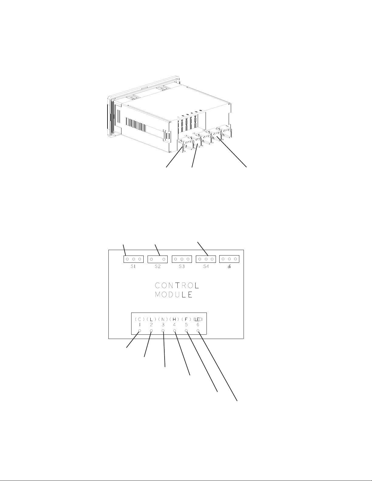
5 VDC
5 VDC
5 VDC
115 VAC
Cabinet
Thermistor
Defrost
Thermistor
1 (C) Compressor (V)
2 (L) Power Supply (BK)
3 (N) Neutral (W)
5 (F) Evaporator Fan Motor (DBU)
4 (H) Defrost Heater (R)
(Freezer)
Defrost Thermistor
Cabinet Thermistor
Door Switch
Door
Switch
6 (LED) Cabinet Lights (Y)
2. Display Layout
3. Control Module Connections

29
B. Temperature
The temperature default scale is °F, but it can be changed to read °C. To change,
see "III.B.3. Changing the Temperature Display Scale (°F or °C)" below.
1. Default Settings
a) Temperature Setpoint:
Model Auxiliary Code Temperature Setpoint
Refrigerator All 38°F (3°C)
Freezer All -2°F (-19°C)
b) Temperature Display Scale: °F.
2. Temperature Setpoint
The temperature setpoint is the value for the average cabinet temperature. The
temperature differential for the compressor to turn on and off is ±3°F (±1.7°C) of the
temperature setpoint. For example, for a refrigerator temperature setpoint of 36°F (2°C),
the compressor comes on at 39°F (3.7°C), and the compressor goes off at 33°F (0.3°C).
If necessary, adjust the temperature setpoint as follows:
1) To change the temperature setpoint, press and release the up or down button.
The current temperature setpoint appears.
2) Press the up or down button until the desired value is displayed. After a few seconds,
the display returns to the current cabinet temperature and the temperature setpoint is
saved. NOTICE! Do not adjust the temperature setpoint more than 2°F (1°C) at a
time. Allow the temperature to stabilize for a minimum of 8hours before making
further temperature setpoint adjustments.
• For refrigerators, the temperature setpoint is adjustable between 31°F and 52°F
(-0.5°C and 11°C). The factory default is 38°F (3°C).
• For freezers, the temperature setpoint is adjustable between -10°F and +12°F (-24°C
and -11°C). The factory default is -2°F (-19°C).
3. Changing the Temperature Display Scale (°F or °C)
To change the temperature display scale, press and hold either the up or down button for
5 seconds. The factory default is °F.

30
C. Defrost
To initiate a manual defrost, press the manual defrost button briey. The defrost icon and
"dEF" appear on the display.
1. Refrigerators
Refrigerators use a time-initiated, off-cycle defrost. Defrost occurs when either the
2-hr.cumulative compressor run timer terminates or the 2-hr. continuous compressor
run timer terminates. When either the 2-hr.cumulative compressor run timer or the
2-hr. continuous compressor run timer terminates, defrost begins. The 5-min. minimum
defrost timer and the 1-hr. maximum defrost timer starts. If energized the compressor
de-energizes and the evaporator fan motor continues. Cabinettemperature is not
displayed during defrost; "dEF" is displayed in its place along with defrost icon. After
the 5-min. minimum defrost timer terminates and the defrost thermistor warms to 44°F
(6.6°C), defrost terminates. The defrost icon turns off and the compressor energizes.
"dEF" is displayed during defrost and continues for 15 min. after defrost termination.
Once the 15-min. "dEF" display timer terminates, cabinet temperature returns to the
display. Note: If the defrost thermistor is above 50°F (10°C) the evaporator fan motor
de-energizes until the defrost thermistor reaches 49°F (9°C).
2. Freezers
Freezers use a time-initiated, heated defrost. Defrost occurs when either the
5-hr.cumulative compressor run timer terminates or the 4-hrcontinuous compressor
run timer terminates. When either the 5 hr. cumulative compressor run timer or the
4-hrcontinuous run timer terminates, defrost begins. The 5-min. minimum defrost
timer and the 1-hr. maximum defrost timer starts. Cabinettemperature is not displayed
during defrost; "dEF" is displayed in its place along with the defrost icon. After the
5-min. minimum defrost timer terminates and the defrost thermistor warms to 77°F
(25°C), defrost terminates (defrost heater de-energizes). A 3-min. compressor delay
timer starts. Once the 3-min. compressor delay timer terminates, the compressor
energizes and a 4-min. evaporator fan motor delay timer (drip time) starts. Once the
4-min. evaporator fan motor delay timer (drip time) terminates, the evaporator fan
motor energizes, the defrost icon turns off, and the 15-min. temperature display delay
timer starts. Once the 15-min. temperature display delay timer terminates, cabinet
temperature is displayed. Note that the 4-min. evaporator fan motor delay time is a
maximum; if the defrost thermistor cools to 15°F (-9.5°C) before the 4-min. evaporator
fan motor delay timer terminates, the evaporator fan motor will energize. Freezers have
a minimum defrost interval of 5hours.
3. Manual Defrost
To initiate a manual defrost, press the manual defrost button.

31
D. Alarm Safeties
Alarm signals are designed to protect the appliance and food product. These alarms
give information or warnings in the event the appliance is operating out of acceptable
parameters. Should one of the alarms occur, follow the instructions in the table below to
address the alarm. The alarm code and alarm icon ash with audible alarm. Tosilence
the alarm, press and release the upper button.
Alarm Signals
Alarm Code Problem Corrective Action/Reset Details
dor
Door Switch Alarm: Door has remained
open for more than 2 minutes.
Door Switch has failed
If obvious corrections such as closing doors does not
correct the alarm, call a qualied service technician.
Beeps for 10 seconds, then silent for 50 seconds. To
silence the alarm, press and release the up button.
E01
Cabinet Thermistor Malfunction Alarm
Cabinet thermistor has failed.
Call a qualied service technician.
Beeps for 10 seconds, then silent for 50 seconds. To
silence the alarm, press and release the up button.
Appliance cycles 5 min. on, 5 min. off.
E02
Defrost Thermistor Malfunction Alarm
Defrost thermistor has failed.
Call a qualied service technician.
Beeps for 10 seconds, then silent for 50 seconds. To
silence the alarm, press and release the up button.
Appliance cycles on and off with cabinet thermistor.
Hi
High Temperature Alarm
Refrigerator: Cabinet temperature has
remained above 57°F (13.9°C) for more
than 2hours.
Freezer: Cabinet temperature has
remained above 26°F (-3.3°C) for more
than 2hours.
If obvious corrections such as closing doors and
cleaning the air lter and/or condenser do not bring
temperature back in range, call a qualied service
technician.
Beeps for 10 seconds, then silent for 50 seconds.
To silence the alarm and clear "Hi" from the display,
press and release the up button. The alarm icon
stays on.
Automatically resets when temperature returns to
normal.
Lo
Low Temperature Alarm
Refrigerator: Cabinet temperature has
remained below 26°F (-3.3°C) for more
than 2hours.
Freezer: Cabinet temperature has
remained below -23°F (-30.6°C) for more
than 2hours.
If obvious corrections do not bring the temperature
back in range, call a qualied service technician.
Beeps for 10 seconds, then silent for 50 seconds.
To silence the alarm and clear "Lo" from the display,
press and release the up button. The alarm icon
stays on.
Automatically resets when temperature returns to
normal.

32
E. Safety Devices and Light Control
1. Compressor External or Internal Protector
If combined temperature/amperage value is above the limit specied by the
compressor manufacturer, the compressor overload operates independently to turn
off the compressor. The compressor overload de-energizes the compressor until the
temperature/amperage value returns to an acceptable level.
2. Short-Cycle Protection
There is a 2-min. minimum off-time and on-time for the compressor.
Note: Time may vary with compressor protector or high-pressure switch activation.
3. High-Pressure Switch
If pressure on the high-side of the appliance exceeds Hoshizaki specications, the
high-pressure switch activates and interrupts the compressor circuit, de-energizing the
compressor until the pressure returns to an acceptable level.
If the condenser fan motor is operating and the compressor is off, it is most likely that the
compressor protector opened. If both the compressor and condenser fan motor are off, it
is most likely the appliance is off or the high-pressure switch has opened.
4. Light Control for Glass Door Models
Glass door models feature lights that are controlled by the standby/light control button
located on the control module. Press and release the standby/light button to turn the light
on or off.
F. Mullion/Perimeter Heater
Refrigerators are equipped with mullion heaters and the freezers are equipped with
mullion and perimeter heaters. The heaters are energized (except PT2A and R_2A
models) when the appliance is plugged into the electrical outlet. Mullion heater
energizes with compressor and condensor fan motor on PT2A and R_2A models.

33
IV. Refrigeration Circuit and Component Service Information
DANGER
Risk of Fire or Explosion Flammable Refrigerant Used
• Follow handling instructions carefully in compliance with U.S. government
regulations.
• Do not use mechanical devices to defrost.
• Do not puncture refrigerant tubing. Risk of re or explosion due to puncture of
refrigerant tubing; follow handling instructions carefully.
• Component parts shall be replaced with like components.
• Servicing shall be done by factory authorized service personnel to minimize the risk
of possible ignition due to incorrect parts or improper service.
• Consult instruction manual/service manual before attempting to install or service
this product.
• Dispose of properly in accordance with federal or local regulations.
• Do not place any potential ignition sources in or near the appliance.
Risque De Feu Ou D'Explosion Le Frigorigène Est Inammable
• Suivre attentivement les instructions de manipulation conformément à la
réglementation gouvernementale.
• Ne pas utiliser d'appareils mécaniques pour dégivrer le réfrigérateur.
• Ne pas perforer la tubulure contenant le frigorigène. Risque de feu ou d'explosion
si la tubulure contenant le frigorigène est perforée; suivre les instructions de
manutention avec soin.
• Les pièces des composants doivent être remplacées par des pièces et accessoires
équivalents.
• L’entretien doit être effectué par le personnel de service autorisé par le fabricant
an de minimiser les risques d’inammation attribuables à l’installation d’une pièce
inadéquate ou à la mauvaise exécution du service.
• Consulter le manuel du propriétaire/guide de réparation avant de tenter une
réparation. Toutes les mesures de sécurité doivent être respectées.
• Éliminer conformément aux règlements fédéraux ou locaux.
• Ne placez aucune source d’inammation potentielle dans ou près de l’appareil.

34
WARNING
• Wear appropriate personal protective equipment (PPE) when servicing the
appliance.
• Technician must utilize a combustible gas leak detector at all times.
• Notify everyone in the immediate area that you are working with ammable
refrigerant.
• Do not work on appliance in a conned space. Conrm area is well ventilated.
• Identify and eliminate all possible ignition points in a 10 ft. (3 m) area around service
area.
• Do not use mechanical devices to defrost.
• Use non-sparking tools.
• Class B dry chemical re extinguisher or equivalent must be available.
• Do not pressurize system above 200 PSIG during leak check procedure or prior to
evacuating refrigeration system.
• This appliance should be diagnosed and repaired only by qualied service
personnel to reduce the risk of death, electric shock, serious injury, or re.
• To reduce the risk of electric shock, do not touch the plug with damp hands.
• Unplug the appliance from the electrical outlet before servicing.
• Make sure all food zones in the appliance are clean after the appliance is serviced.

35
A. Service for Refrigerant Lines
WARNING
• Repairs requiring the refrigeration circuit to be opened must be performed by
properly trained and EPA-certied service personnel.
• Use an electronic leak detector or soap bubbles to check for leaks. Add a trace
of refrigerant to the system (if using an electronic leak detector), and then raise
the pressure using nitrogen gas (140 PSIG). Do not use R-290 as a mixture with
pressurized air for leak testing.
NOTICE
• Always recover the refrigerant and store it in an approved container. Do not
discharge the refrigerant into the atmosphere.
• Do not leave the system open for longer than 15 minutes when replacing or
servicing parts. The Polyol Ester (POE) oils used in R-290 appliances can absorb
moisture quickly. Therefore it is important to prevent moisture from entering the
system when replacing or servicing parts.
• Always install a new drier every time the sealed refrigeration system is opened.
Do not replace the drier until after all other repair or replacement has been made.
Install the new drier with the arrow on the drier in the direction of the refrigerant
ow.
• When brazing, protect the drier by using a wet cloth to prevent the drier from
overheating. Do not allow the drier to exceed 250°F (121°C).
Refrigerant leaks must be repaired as soon as they are discovered. If not, refrigerant
charge should be recovered from the system until the leak can be repaired.
When repairing a leak:
• Repair the leak properly – Remove the refrigerant, examine the leak source, determine
the reason for the leak, and carry out the proper course of action.
• Before repairing the leak, ensure that the refrigerant has been recovered and the
system purged with nitrogen when brazing.
• Be sure to remove piercing valves attached to the system after repairs are made.
1. Refrigerant Recovery
Using proper refrigerant practices, place piercing valves toward the end (crimped area)
of the high and low-side process tubes, then recover the refrigerant into an approved
container or device.

36
2. Brazing
DANGER
Risk of Fire or Explosion Flammable Refrigerant Used
• Servicing shall be done by factory authorized service personnel to minimize the risk
of possible ignition due to incorrect parts or improper service.
Risque De Feu Ou D'Explosion Le Frigorigène Est Inammable
• L’entretien doit être effectué par le personnel de service autorisé par le fabricant
an de minimiser les risques d’inammation attribuables à l’installation d’une pièce
inadéquate ou à la mauvaise exécution du service.
WARNING
• Wear appropriate personal protective equipment (PPE) when servicing the
appliance.
• You must have a combustible gas leak detector in the immediate work area at all
times.
• You must have a Class B chemical re extinguisher available at all times.
• Notify all persons in the immediate area that you are working with a ammable
refrigerant.
• Do not use silver alloy or copper alloy containing arsenic.
• Be sure the area is clear of refrigerant vapor before brazing.
1) Purge with nitrogen for 2 min. WARNING! Purging with nitrogen gas assures all
refrigerant has been removed from the refrigeration circuit.
2) Braze/repair/replace damaged component or ttings while purging with nitrogen gas
owing at a pressure of 3 to 5 PSIG.
NOTICE
• Always install a new drier every time the sealed refrigeration system is opened.
• Do not replace the drier until after all other repair or replacement has been made.
Install the new drier with the arrow on the drier in the direction of the refrigerant
ow.
• When brazing, protect the drier by using a wet cloth to prevent the drier from
overheating. Do not allow the drier to exceed 250°F (121°C).
3) Use soap bubbles to check for leaks. Raise the pressure using nitrogen gas (190 PSIG).
Do not use any refrigerant as a mixture with pressurized air for leak testing.
4) Once leak checking is complete, release the nitrogen gas from the system.

37
3. Evacuation
1) Attach a vacuum pump to the system. Be sure to connect the charging hoses to both
high and low-side refrigerant piercing valves.
IMPORTANT
The vacuum level and vacuum pump may be the same as those for current
refrigerants. However, the rubber hose and gauge manifold to be used for
evacuation and refrigerant charge should be exclusively for POE oils.
2) Turn on the vacuum pump, then open the gauge manifold valves. Never allow the oil in
the vacuum pump to ow backwards.
3) Allow the vacuum pump to pull down to a 29.9" Hg vacuum (500 microns). Evacuating
period depends on pump capacity.
4) Close the low-side valve and high-side valve on the gauge manifold.
5) Disconnect the gauge manifold hose from the vacuum pump and attach it to a
refrigerant service cylinder. Remember to loosen the connection and purge the air
from the hose. For the required refrigerant charge, see the nameplate. Hoshizaki
recommends only virgin or reclaimed refrigerant which meets ARI Standard 700 (latest
edition) be used.
4. Recharge
6) R-290 can be charged in either the liquid or vapor state. A liquid charge is preferred.
Service kit SP-5459 is recommended when recharging an R-290 refrigeration circuit.
Connect the refrigerant hose to the service cylinder and bleed air out of refrigerant
hose. Next, invert the service cylinder and place it on the scales. Zero out the scales.
Open the high-side valve on the gauge manifold.
7) Allow the system to charge with liquid until the proper charge weight is met.
8) Close the high-side valve on the gauge manifold. If charging is complete, skip to step 10.
9) If necessary, add any remaining charge to the system through the low-side.
NOTICE!To prevent compressor damage, use a throttling valve or liquid
dispensing device to add the remaining liquid charge through the low-side
refrigerant access valve with the compressor running. Close the refrigerant cylinder
valve and let the low-side refrigerant equalize to the system, then close the low-side
manifold gauge. Unplug the appliance from the electrical outlet.
10) Remove the refrigerant hose from the service cylinder. Pinch off (crimp down) the
process tubes just below the piercing valves.
11) Remove the piercing valves. Cut the process tubes to remove the piercing valve holes
then braze the process tubes closed. Note: Be sure there is no refrigerant leak or
refrigerant in the area before brazing.
12) Use a combustible gas leak detector or soap bubbles to check for leaks again.
13) Place red sleeves over the process tubes.
14) Plug the appliance back into the electrical outlet. Allow the appliance to cool to setpoint
before reloading.

38
B. Component Service Information
DANGER
• Component parts shall be replaced with like components.
• Les pièces des composants doivent être remplacées par des pièces et accessoires
équivalents.
NOTICE
When replacing a component listed below, see the notes to help ensure proper
operation.
Component Notes
Compressor Install a new start relay and compressor external protector. WARNING! To reduce the
risk of electric shock, be sure to reconnect the compressor's ground wire.
Thermostatic
Expansion Valve
• Attach the thermostatic expansion valve bulb to the suction line in the same location as
the previous bulb.
• The bulb should be between the 10 and 2 o'clock positions on the tube.
• Secure the bulb with the clamp and holder.
Defrost Thermis-
tor
After working with or around the defrost thermistor on a freezer, make sure the defrost
thermistor wire is not touching the defrost heater.
C. Door Reversal
The appliance is provided with a cabinet design which, after being delivered to the
installation location, permits changing of the door swing from left to right or right to left.
To change the door swing, See Instruction Manual "I.F. Door Reversal".
NOTICE! Improper installation may result in the doors not closing completely and/
or the gaskets not sealing correctly. For further details, contact your local Hoshizaki
distributor or Hoshizaki Technical Support at 1-800-233-1940.

39
V. Maintenance
WARNING
• Unplug the appliance before performing maintenance to prevent electric shock or
injury by moving parts. To reduce the risk of electric shock, do not touch the plug
with damp hands.
• Before performing maintenance, move all foods into another clean refrigerator or
freezer.
1. Air Filter
Check the air lter at least twice a month. When clogged, use warm water and a neutral
cleaner to wash the lter.
2. Condenser
Inspect the condenser air lter bi-weekly. Wash with warm water and neutral cleaner if
dirty. Check the condenser once a year and use a brush or vacuum cleaner to clean the
condenser as required.
3. Condensate Wick (Except DT1A-HS and Freezer on DT2A-FS)
The condensate wick must be cleaned at least once a year. More frequent cleaning may
be required in some conditions to maintain proper ow. Follow the steps below.
1) Unplug the appliance from the electrical outlet. WARNING! To reduce the risk of electric
shock, do not touch the plug with damp hands.
2) Remove the wick from the retainers.
3) Clean or replace the wick. NOTICE! If the wick is clogged/deteriorating replace.
4) Replace the wick in its correct position.
NOTICE! Be sure the wick is positioned into the condensate pan.
Fig. 1
Wick
Retainer
Retainer
Retainer
Retainer
Wick
5) Plug the appliance back in.
4. Power Supply Connection
If the plug or power cord is damaged, contact your local Hoshizaki service representative
or local Hoshizaki distributor immediately and ask for repairs.
All other maintenance or service on this appliance should be performed in accordance
with the Hoshizaki Instruction Manual by a qualied service technician.

40
VI. Preparing the Appliance for Periods of Non-Use
WARNING
Prevent the doors from closing to reduce the risk of children getting trapped.
NOTICE
Clean the cabinet interior, door gaskets, and shelves.
1) Before shutting down the appliance, move the stored food into another refrigerator or
freezer.
2) Unplug the appliance. WARNING! To reduce the risk of electric shock, do not touch
the plug with damp hands.

41
VII. Disposal
DANGER
Risk of Fire or Explosion Flammable Refrigerant Used
• Follow handling instructions carefully in compliance with U.S. government
regulations.
• Do not puncture refrigerant tubing. Risk of re or explosion due to puncture of
refrigerant tubing; follow handling instructions carefully.
• Dispose of properly in accordance with federal or local regulations.
Risque De Feu Ou D'Explosion Le Frigorigène Est Inammable
• Suivre attentivement les instructions de manipulation conformément à la
réglementation gouvernementale.
• Ne pas perforer la tubulure contenant le frigorigène. Risque de feu ou d'explosion
si la tubulure contenant le frigorigène est perforée; suivre les instructions de
manutention avec soin.
• Éliminer conformément aux règlements fédéraux ou locaux.
WARNING
When preparing the appliance for disposal, remove the doors/drawers to reduce the
risk of children getting trapped. Leave any shelves in place so that children may not
easily climb inside.
The appliance contains refrigerant and must be disposed of in accordance with
applicable national, state, and local codes and regulations. Refrigerant must be
recovered by properly certied service personnel.

42
VIII. Technical Information
A. Electrical and Refrigerant Data
Model
AC Supply
Voltage Amperes
Refrigerant
(oz.)
Design Pressure
(PSIG)
R290 HIGH LOW
R1A-FG/FGCL/FGCR//HG
R1A-FS/FSJ/FSL/FSLJ/HS/HSL
PT1A-FG-FG/FS-FS/HS-HS
115/60/1
5 4.6
360 190
R2A-FG/HG/FS/HS
8
4.9
PT2A-FS-FS/HS-HS/FG-FG 5.3
R3A-FS/HS
9.5
4.6 Right
4.6 Left
RN1A-FS
RT1A-FS-FS
6.4 4.6
RN2A-FS
RT2A-FS-FS
8.2 5.1
F1A-FG/FS/FSL/HG/HS/HSL 9 4.1
F2A-FG/HG/FS/HS 9.5 4.2
F3A-FS/HS 208-230/115/60/1 11
4.1 Right
4.1 Left
DT1A-HS 115/60/1
5.5
Freezer
2.5
Refrigerator
2.1
DT2A-FS/HS 115/60/1 14
Freezer
4.1
Refrigerator
4.6
See the nameplate for electrical and refrigerant data. The nameplate is located inside the
cabinet. We reserve the right to make changes in specications and design without prior
notice.

43
B. Wiring Diagrams
1. R1A/R2A/F1A-FG/FGCL/FGCR/FS/FSJ/FSL/FSLJ/HG/HS/HSL,
PT1A-FG-FG/FS-FS/HS-HS
5 to 12VDC
115 VAC
Glass Door LEDs Controlled Through
Control Module Light Switch.
Solid Door LEDs Controlled Through Door Switch.
*
* High-Pressure Switch
Cut-out 360±
30
PSIG
Cut-in 249±10 PSIG
0

44
2. RN1A-FS, RT1A-FS-FS
*
* High-Pressure Switch
Cut-out 360±
30
PSIG
Cut-in 249±10 PSIG
0
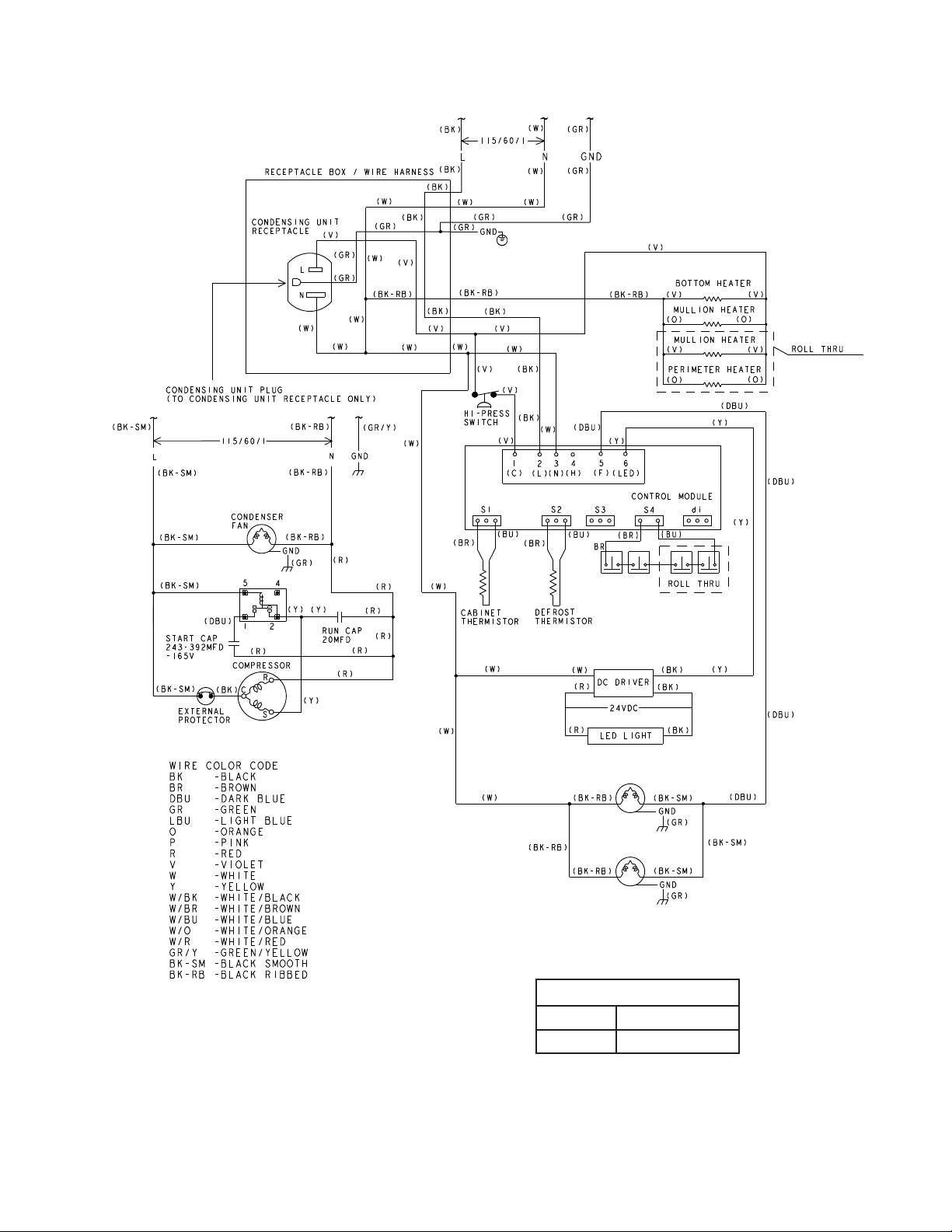
45
3. RN2A-FS, RT2A-FS-FS
*
* High-Pressure Switch
Cut-out 360±
30
PSIG
Cut-in 249±10 PSIG
0

46
5 to 12VDC
115 VAC
Glass Door LEDs Controlled Through
Control Module Light Switch.
Solid Door LEDs Controlled Through Door Switch.
*
* High-Pressure Switch
Cut-out 360±
30
PSIG
Cut-in 249±10 PSIG
0
4. PT2A-FG-FG/FS-FS/HS-HS

47
5. R3A-FG/FGCL/FGCR/FS/FSCL/FSCR/HS/HG
5 to 12VDC
115 VAC
Glass Door LEDs Controlled Through
Control Module Light Switch.
Solid Door LEDs Controlled Through Door Switch.
*
*
* High-Pressure Switch
Cut-out 360±
30
PSIG
Cut-in 249±10 PSIG
0

48
6. F2A-FG/FS/HG/HS
5 to 12VDC
115 VAC
Glass Door LEDs Controlled Through
Control Module Light Switch.
Solid Door LEDs Controlled Through Door Switch.
*
* High-Pressure Switch
Cut-out 360±
30
PSIG
Cut-in 249±10 PSIG
0

49
7. F3A-FS/HS
5 to 12VDC
115 VAC
Solid Door LEDs Controlled Through Door Switch.
*
*
* High-Pressure Switch
Cut-out 360±
30
PSIG
Cut-in 249±10 PSIG
0
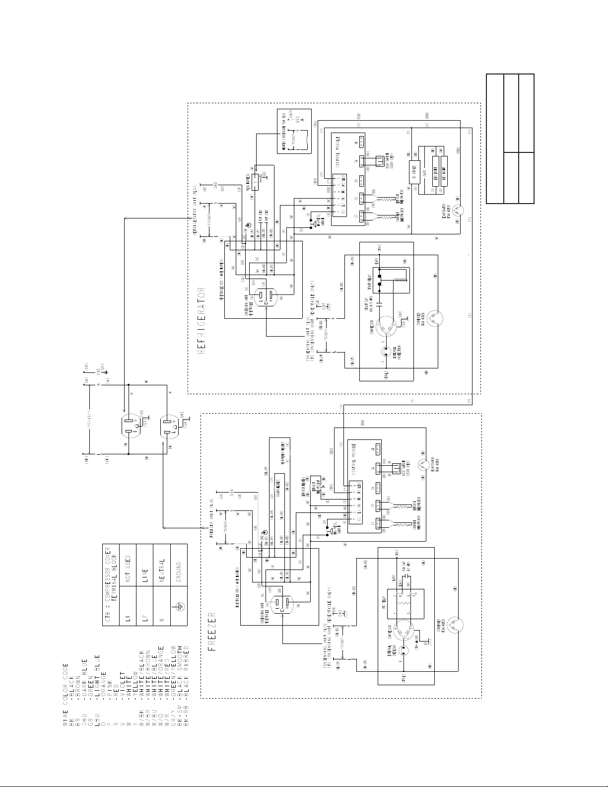
50
8. DT1A-HS
*
*
* High-Pressure Switch
Cut-out 360±
30
PSIG
Cut-in 249±10 PSIG
0

51
9. DT2A-FS/HS
5 to 12VDC
115 VAC
Glass Door LEDs Controlled Through
Control Module Light Switch.
Solid Door LEDs Controlled Through Door Switch.
*
Main Connection
System Connection
* High-Pressure Switch
Cut-out 360±
30
PSIG
Cut-in 249±10 PSIG
0