Loading ...
Loading ...
Loading ...
13
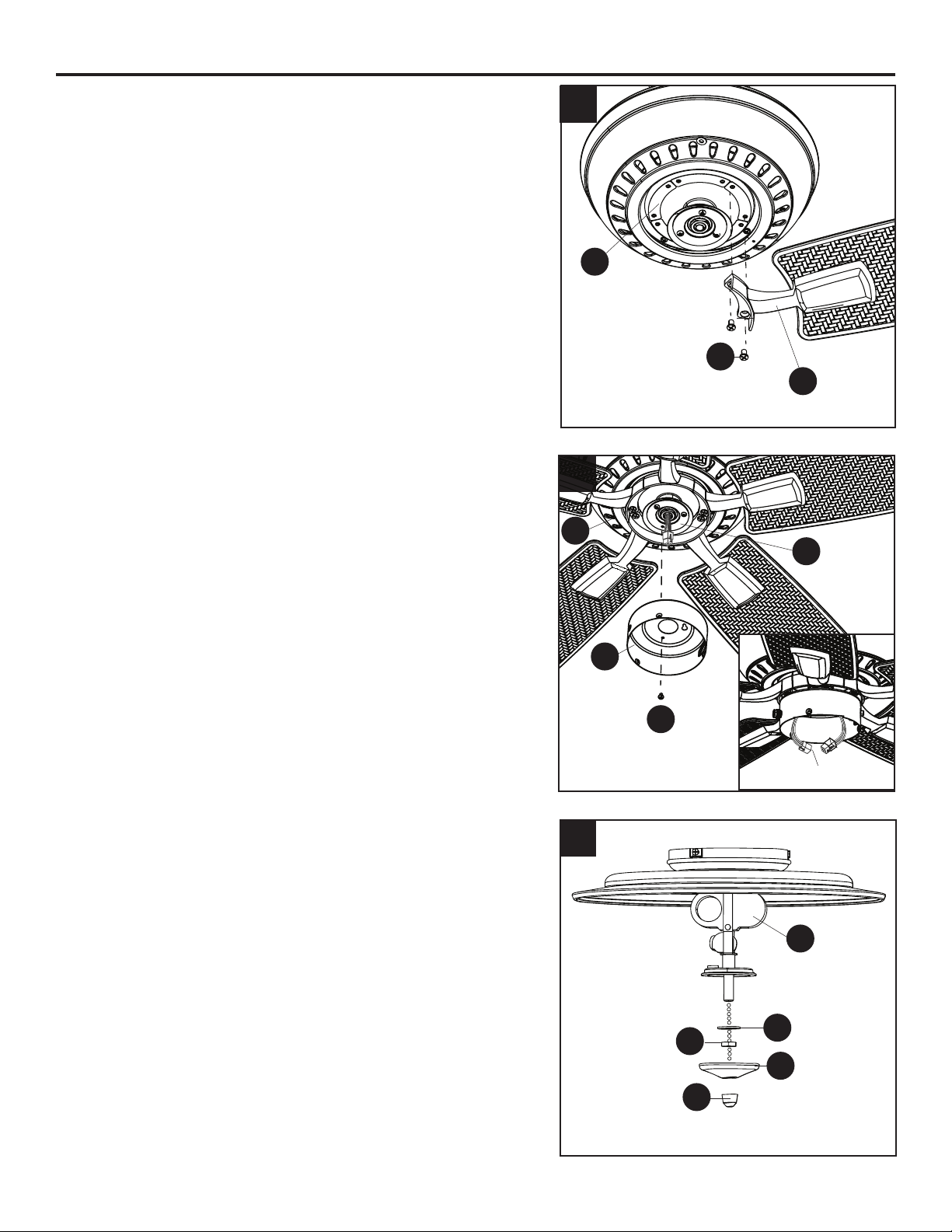
FINAL INSTALLATION
4. Install the blade arm (Y) to the underside of the motor
assembly (H) with motor screws (J) previously removed
(Step 6, page 8). Tighten with Phillips screwdriver.
Repeat for each blade arm (Y).
5. Remove one of the tter plate screws (L) from the tter
plate (K), and loosen (do not remove) the other two
screws.
Insert the 9-pin connector from tter plate (K) through the
hole in the switch housing (M). Then, attach the switch
housing (M) to the tter plate (K) by twisting the switch
housing (M) until the loosened tter plate screws (L)
engage the keyholes on switch housing (M).
Re-install the third tter plate screw (L) into the closed
hole in the switch housing (M) and securely tighten all
three tter plate screws (L).
Connect the 9-pin connector from the tter plate (K) to
the 9-pin connector from the switch housing (M).
6. Remove the preassembled nial (U), nial cap (T), hex
nut (R) and rubber washer (S) from the light kit (Q).
4
Y
J
H
6
5
Q
L
M
K
H
S
R
T
U
9-pin Connector
Loading ...
Loading ...
Loading ...