Loading ...
Loading ...
Loading ...
11
WIRING
WARNING: To reduce the risk of re, electrical shock or personal injury, wire connectors
provided with this fan are designed to accept only one 12-gauge house wire and two lead wires from
the fan. If your house wire is larger than 12-gauge and there is more than one house wire to connect
to the two fan lead wires, consult an electrician for the proper size wire connectors to use.
CAUTION: Be sure the outlet box is properly grounded or that a ground (green or bare) wire is present.
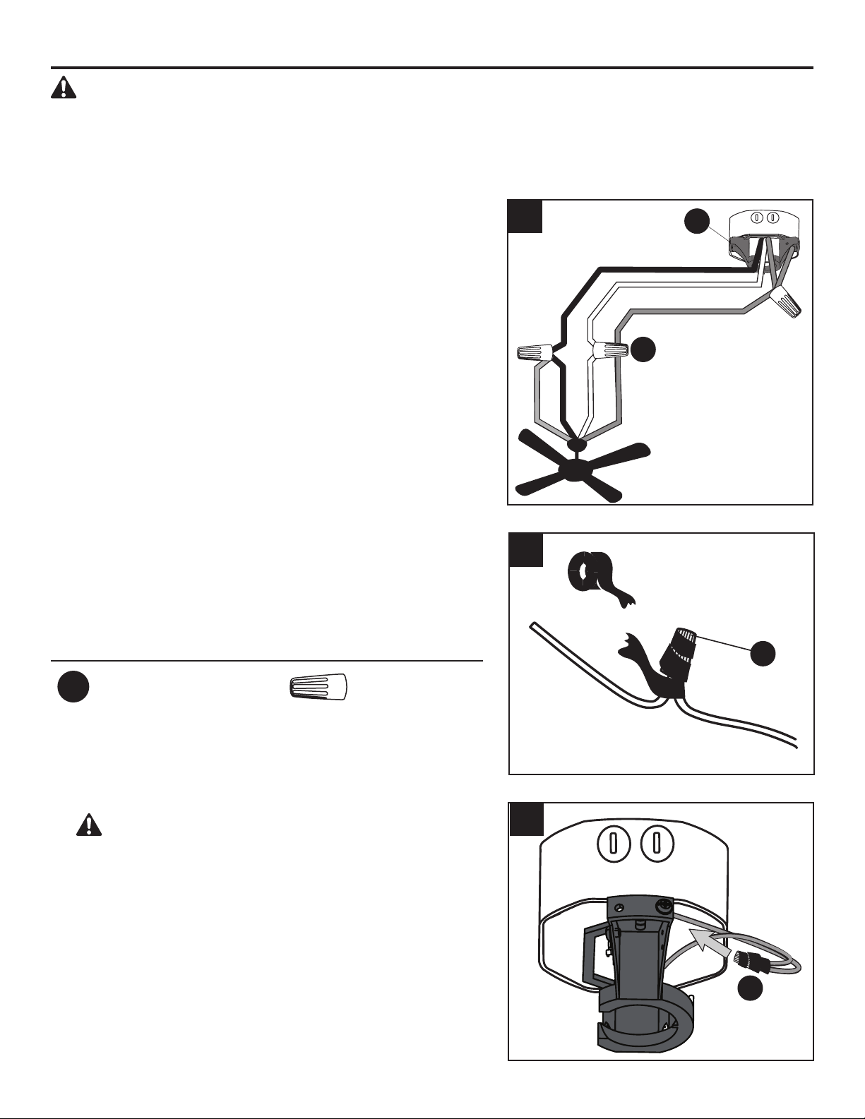
1. Connect household supply and fan wires according to
the diagram and these steps:
• Connect the Green wire from the downrod (A) and
mounting bracket (D) to the Bare/Green (ground)
supply wire.
• Connect the White wire from the fan to the White
(neutral) supply wire.
• Connect the Black and Blue wires from the fan to the
Black (hot) supply wire.
• Secure all wiring connections together with wire
connectors (AA).
Note: If there is a second hot/power wire coming from
the outlet box, connect it to the Blue (light power) fan
wire for separate light and fan control.
Note: The Black wire is hot power for the fan. The
White wire is common for the fan and light kit. The
Blue wire is hot power for light. The Green wire is the
ground wire. If household supply wires are dierent
colors than referred to above, it is recommended a
professional electrician determines the proper wiring.
Hardware Used
AA
Wire Connector x 3
Black (Hot)
White (Neutral)
Bare/Green (Ground)
Black
Blue
White
Green
2. Wrap electrical tape (not included) around each
individual wire connector (AA) down to the wire.
3. Turn the spliced/taped wires upward and gently push
the wires and wire connectors (AA) into the outlet box.
WARNING: Ensure no bare wire or wire strands
are visible after making connections. Place the
Green and White wire connections on the opposite
side of the outlet box from the Black and Blue wire
connections.
1
3
AA
AA
AA
D
2
Loading ...
Loading ...
Loading ...