Loading ...
Loading ...
Loading ...
SONANCE
|
PROFESSIONAL SERIES SURFACE MOUNT
|
INSTALLATION MANUAL 4
WIRE GAUGE – 70V/100V SYSTEM
The most common wire used on commercial 70 volt systems is
18 gauge, 2 conductor, stranded, and jacketed without a shield.
The wire starts at the amplifier location and is paralleled at each
speaker location.
Wire length using 18 gauge is appropriate up to 700 feet with a
100 watt load. If you double the load (sum of your tap settings),
you will reduce the footage by half, to 350 feet. Conversely, if you
halve the load, you may double the acceptable wire length, i.e.,
a 50 watt load is safe over 1400 feet of 18 gauge. Stepping up to
16 gauge wire extends the allowable run length by approximately
35%. For example, a 100 watt load can go 700 feet on 18 gauge;
the same load may be placed on 1100 feet of 16 gauge.
WIRE GAUGE – 8 OHM SYSTEM
When using Sonance Professional Series loudspeakers in an 8
ohm system the total wire resistance should be less than 10%
of the speaker impedance. The speakers are nominally 8 ohms
impedance, so your total wire resistance should be no more than
0.8 ohms.
In simple terms, the extra resistance from the wire will have a very
negative affect on the sound quality of the speaker. The sound can
be less dynamic, definition of bass frequencies can be reduced,
and in extreme cases, the high frequencies can be attenuated.
Amplifier power is also wasted in the wire, reducing the maximum
output level of the system.
Please refer to the following chart (see figure 1) when deciding on
the appropriate wire gauge for your installation.
Wire Resistance in Ohms vs. Length of Cable Run
20 Gauge
50’ 100’ 150’ 200’ 250’ 300’
.86 1.73 2.59 3.45 4.32 5.18
.65 1.30 1.94 2.59 3.24 3.89
.43 .85 1.28 1.71 2.14 2.56
.27 .54 .81 1.08 1.35 1.62
.17 .34 .51 .68 .85 1.02
Distance in Feet
18 Gauge
16 Gauge
14 Gauge
12 Gauge
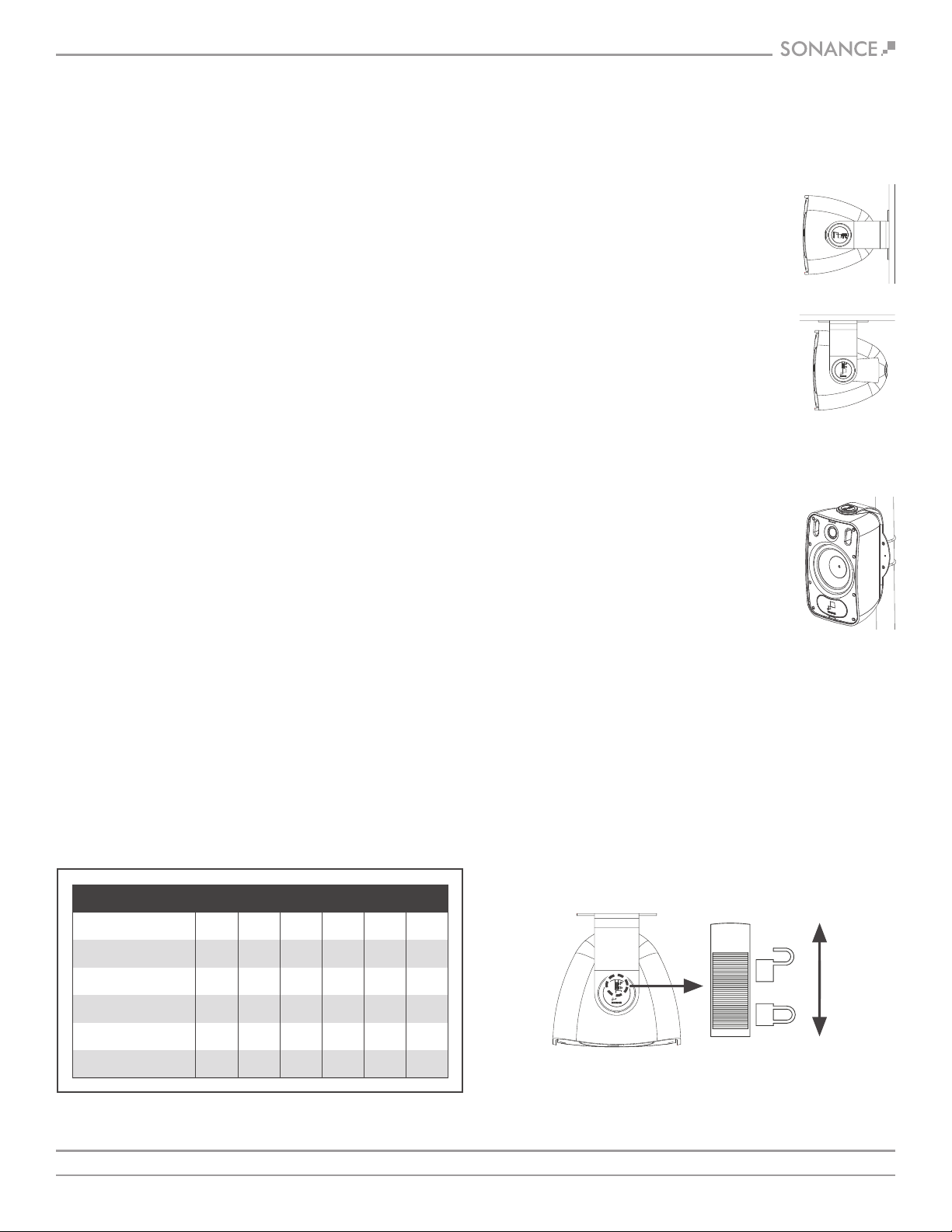
PIVOTING THE SPEAKERS
You can rotate the speaker in the bracket to direct the sound
towards the listeners.
1. Unlock the slide locks on the speaker pivots by moving them
towards the rear of the speaker (see figure 4).
2. Rotate the speakers to the desired position.
3. Lock the slide locks by moving them towards the front of the speaker.
AMPLIFIER SELECTION
When choosing an amplifier the maximum number of speakers
and the output level of each speaker must be known. The sum of
the tap settings should never exceed 80% of the amplifier’s rated
output. For example, if there are 5 speakers and the taps are set
at 15 watts, the load would be 75 watts (5 x 15 watts = 75 watts).
To arrive at the needed power for this number of speakers, simply
divide the total load by .8. In this case, 75 / .8 = 93.75 watts.
Therefore, a standard 100 watt amp would safely drive this load.
To calculate the amount of usable power an amp offers, simply
multiply the rated output by .8, i.e., 100 watts x .8= 80 watts.
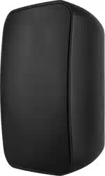
SPEAKER PLACEMENT
Sonance Professional Series speakers possess extremely smooth and
predictable off-axis frequency response. The FastMount mounting
system makes it easy to mount the speakers in a variety of positions
and locations (see figure 2 and 3):
WALL/CEILING MOUNTING
It is important that the bracket is securely
mounted onto a structurally sound surface,
capable of withstanding the weight of the
product and any vibration created by the
operation of the speaker. Four screws points
must be used at all times. A screw size of #14
to #20 diameter x 2” length or M6 to M8
diameter x 50mm length is recommended.
When mounting onto drywall or plasterboard,
the bracket should be affixed to a joist or stud.
When mounting onto brick or concrete, wall
plugs or concrete anchors should be used.
POLE MOUNTING
To mount the speaker on a pole, 2 x U-bolts
and nuts should be used to clamp around the
pole and bolt through the 4 holes on the back
of the FastMount bracket. Spring washers or
blue thread lock are recommended to ensure
the nuts do not work loose through the
vibration of the speaker.
UNLOCK
(towards rear
of speaker)
LOCK
(towards front
of speaker)
Wall mount
Ceiling mount
UNLOCK
(towards rear
of speaker)
LOCK
(towards front
of speaker)
Pole mount
FIGURE 4:
LOCK AND UNLOCK SLIDE LOCKS TO PIVOT SPEAKER
FIGURE 2:
WALL MOUNT &
CEILING MOUNT
FIGURE 3:
POLE MOUNT
FIGURE 1: WIRE RESISTANCE
Loading ...
Loading ...
Loading ...