20V BRUSHLESS
DIGITAL COMPACT ROUTER
241-0340
OPERATOR’S MANUAL
CAUTION: To Reduce The Risk Of Injury, User Must Read And
Understand Operator's Manual. Save These Instructions For Future Reference.
For questions about this product, please call 1-866-915-8626

IMPORTANT SAFETY INSTRUCTIONS 2
SPECIFICATIONS 5
FUNCTION 5
ASSEMBLY 5
OPERATION 6
MAINTENANCE 10
PARTS LIST 11
SCHEMATIC DRAWING 12
TABLE OF CONTENTS

WARNING:
When using electric tools, machines or
equipment, basic safety precautions should
electric shock, and personal injury.
WORK AREA SAFETY
1. Keep the work area clean and well lit.
Cluttered or dark areas invite accidents.
2. Do not operate power tools in explosive
atmospheres, such as in the presence of
liquids, gases or dust. Power
tools create sparks, which may ignite the
dust or fumes.
3. Keep children and bystanders away
while operating a power tool.
Distractions
can cause you to lose control.
ELECTRICAL SAFETY
1. Power tool plugs must match the outlet.
Never modify the plug in any way. Do
not use any adapter plugs with earthed
(grounded) power tools.
plugs
and matching outlets will reduce risk of
electric shock.
2. Avoid body contact with earthed or
grounded surfaces, such as pipes,
radiators, ranges and refrigerators.
There
is an increased risk of electric shock if your
body is earthed or grounded.
3. Do not expose power tools to rain or wet
conditions.
Power tools exposed to water
4. Do not abuse the cord. Never use the
cord for carrying, pulling or unplugging the
power tool. Keep cord away from heat, oil,
sharp edges or moving parts. Damaged
or entangled cords increase the risk of
electric shock.
5. When operating a power tool outdoors,
use an extension cord suitable for outdoor
use. Use of an outdoor cord reduces the risk
of electric shock.
6. If operating a power tool in a damp
location is unavoidable, use a ground-fault
circuit interrupter (GFCI) protected supply.
Use of a GFCI reduces the risk of electric shock.
PERSONAL SAFETY
1. Stay alert, watch what you are doing and
use common sense when operating a power
tool. Do not use a power tool while you are
tired or under the in
uence of drugs, alcohol
or medication. A moment of inattention while
operating power tools may result in serious
personal injury.
2. Use personal protective equipment.
Always wear eye protection. Protective
equipment such as dust mask, non-skid
safety shoes, hard hat, or hearing protection
used for appropriate conditions will reduce
personal injuries.
3. Prevent unintentional starting. Ensure
the switch is in the off-position before
connecting to power source and/or battery
pack, picking up or carrying the tool.
switch or energising power tools that have
the switch on invites accidents.
4. Remove any adjusting key or wrench before
turning the power tool on. A wrench or a key
left attached to a rotating part of the power tool
may result in personal injury.
5. Do not overreach. Keep proper footing
and balance at all times. This enables better
control of the power tool in unexpected
situations.
6. Dress properly. Do not wear loose clothing
or jewelry. Keep your hair, clothing and
gloves away from moving parts. Loose
clothes, jewelry or long hair can be caught
in moving parts.
7. If devices are provided for the connection
of dust extraction and collection facilities,
Page 2
IMPORTANT SAFETY INSTRUCTIONS
will increase the risk of electric shock.

ensure that these are connected and
properly used. Use of these devices can
reduce dust-related hazards.
POWER TOOL USE AND CARE
1. Do not force the power tool. Use the
correct power tool for your application. The
correct power tool will do the job better and
more safely at the rate for which it was
designed.
2. Do not use the power tool if the switch
can not be turned on or off. Any power tool
that cannot be controlled with the switch is
dangerous and must be repaired.
3. Disconnect the plug from the power
source and/or the battery pack from the
power tool before making any adjustments,
changing accessories, or storing power
tools. Such preventive safety measures
reduce the risk of starting the power tool
accidentally.
4. Store power tools out of the reach
of children and do not allow persons
unfamiliar with the power tool or these
instructions to operate the power tool.
Power tools are dangerous in the hands of
untrained users.
5. Maintain power tools. Check for
misalignment or binding of moving parts,
breakage of parts and any other condition
that may affect the power tool’s operation.
If damaged, have the power tool repaired
before use. Many accidents are caused by
poorly maintained power tools.
6. Keep cutting tools sharp and clean.
Properly maintained cutting tools with sharp
cutting edges are less likely to bind and are
easier to control.
7. Use the power tool, accessories, tool bits,
etc. in accordance with these instructions,
taking into accou
nt the working conditions
and the work to be performed. Use of the
power tool for operations different from those
intended could result in a hazardous situation.
BATTERY TOOL USE AND CARE
1. Recharge only with the charger
by the manufacturer. A charger that is
suitable for one type of battery pack may
create a risk of re when used with another
battery pack.
yllacificeps htiw ylno sloot rewop esU .2
designated battery packs. Use of any other
battery packs may create a risk of injury
re.
3. When battery pack is not in use, keep
it away from other metal objects like
paper clips, coins, keys, nails screws or
other small metal objects that can make a
connection from one terminal to another.
Shorting the battery terminals together may
cause bur
re.
4. Under abusive conditions, liquid may be
ejected from the battery; If contact
accidentally occurs, flush with water.
If liquid contacts eyes, also seek medical
help. Liquid ejected from the battery may
cause irritation or burns.
SERVICE
1. Have your power tool serviced by a
repair person and use only identical
replacement parts. This will ensure that the
safety of the power tool is maintained.
Page 3
IMPORTANT SAFETY INSTRUCTIONS

SPECIFIC SAFETY RULES
FOR ROUTER
Page 4
IMPORTANT SAFETY INSTRUCTIONS
DANGER:
People with electronic
devices, such as pacemakers, should
consult their physician(s) before using this
product. Operation of electrical equipment
in close proximity to a heart pacemaker
could cause interference or failure of the
pacemaker.
WARNING:
Some dust created by
power sanding, sawing, grinding, drilling
and other construction activities contains
chemicals known to the state of California
to cause cancer, birth defects or other
reproductive harm. Some examples of
these chemicals are:
• Lead from lead-based paints
• Crystalline silica from bricks and cement
and other masonry products, and
• Arsenic and chromium from
chemically-treated lumber.
Your risk from these exposures varies,
depending on how often you do this type
of work. To reduce your exposure to these
chemicals: work in a well ventilated area,
and work with approved safety equipment,
such as those dust masks that are specially
designed to filter out microscopic particles.
1.Hold power tool by insulated gripping
surfaces, because the cutter may contact
hidden wiring. Cutting a “live” wire may
make exposed metal parts of the power
tool “live” and shock the operator.
2.Use clamps or another practical way to
secure and support the workpiece to a
stable platform. Holding the work by your
hand or against the body leaves it unsta-
ble and may lead to loss of control.
3.Wear hearing protection during extend-
ed period of operation.
4.Handle the ROUTER bits very carefully.
5.Check the trimmer bit carefully for cracks
or damage before operation. Replace
cracked or damaged bit immediately.
6.Avoid cutting nails. Inspect for and
remove all nails from the workpiece
before operation.
8.Keep hands away from rotating parts.
9.Hold the trimmer bit away from the
workpiece before the switch is turned on.
10.Before using the tool on an actual
workpiece, let it run for a while. Watch for
vibration or wobbling that could indicate
improperly installed bit.
11.Be careful of the rotating direction and
the feed direction of the trimmer bit.
12.Do not leave the tool running. Operate
the tool only when hand-held.
13.Always switch off and wait for the
trimmer bit to come to a complete stop
before removing the tool from workpiece.
14.Do not touch the trimmer bit immedi-
ately after operation; it may be extremely
hot and could burn your skin.
15.Do not smear the tool base carelessly
with thinner, gasoline, oil or the like. They
may cause cracks in the tool base.
16.Use trimmer bits of the correct shank
diameter suitable for the speed of the tool.
17.Some material contains chemicals
which may be toxic. Take caution to
prevent dust inhalation and skin contact.
Follow material supplier safety data.
18.Always use the correct dust mask/
respirator for the material and application
you are working with.
Page 5
Variable speed: 10,000-30,000 RPM (no-load)
Collet capacity: 1/4", 3/8"
Base diameter: 3-1/2”
Base opening: 1-3/8"
Plunge depth: 7/8”
Contents: router motor, fixed base, 1/4" collet, 3/8" collet, roller guide, straight edge guide,
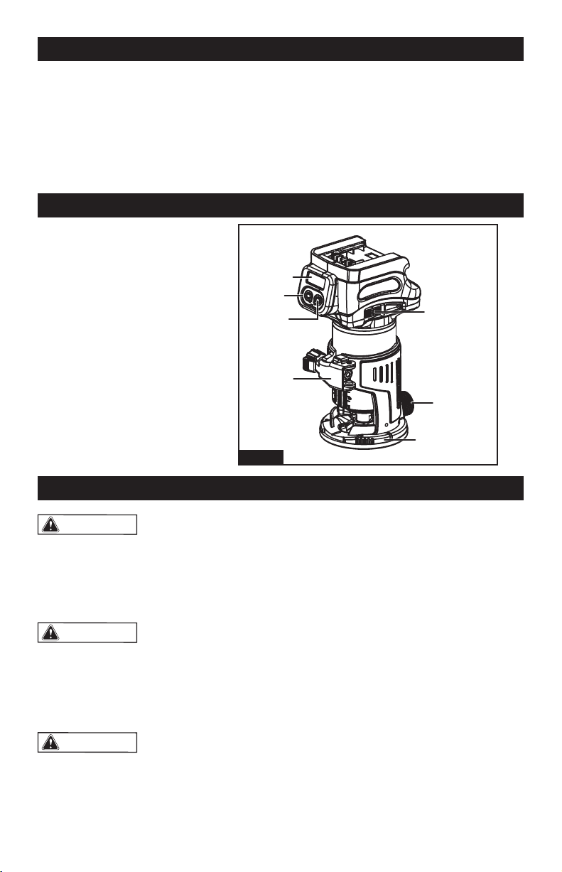
dust hood attachment, wrench, and instruction manual
2. Lock/unlock button
1. Digital display
3. Start/stop button
4. Speed adjusting dial
5. Lock lever
6. Clamp screw
7. Router base
FUNCTION
WARNING:
If any part is broken or
missing, DO NOT attempt to plug in the
power cord, attach the battery, or operate
the tool until the broken or missing part is
replaced. Failure to do so could result in
possible serious injury.
WARNING:
Do not attempt to modify
this tool or create accessories that are not
recommended for use with thi s tool. Any
such alteration or modification could result
in a hazardous condition including possible
serious body injury.
WARNING:
Your tool should never
be connected to the power source when
you are assembling parts, making adjust-
ments, installing or removing application
tools, cleaning, even when it is not in use.
Disconnecting the tool will prevent acci-
dental starting, which could cause serious
personal injury.
UNPACKING
1. Carefully remove the tool and any
accessories from the box. Make sure that all
items listed in the packing list are included.
2. Inspect the tool carefully to make sure
that no breakage or damage occurred during
shipping.
3. Do not discard the packing material until
you have carefully inspected and satisfactorily
operated the tool.
ASSEMBLY
SPECIFICATIONS
2
3
5
7
6
4
1
Fig.1
Page 6
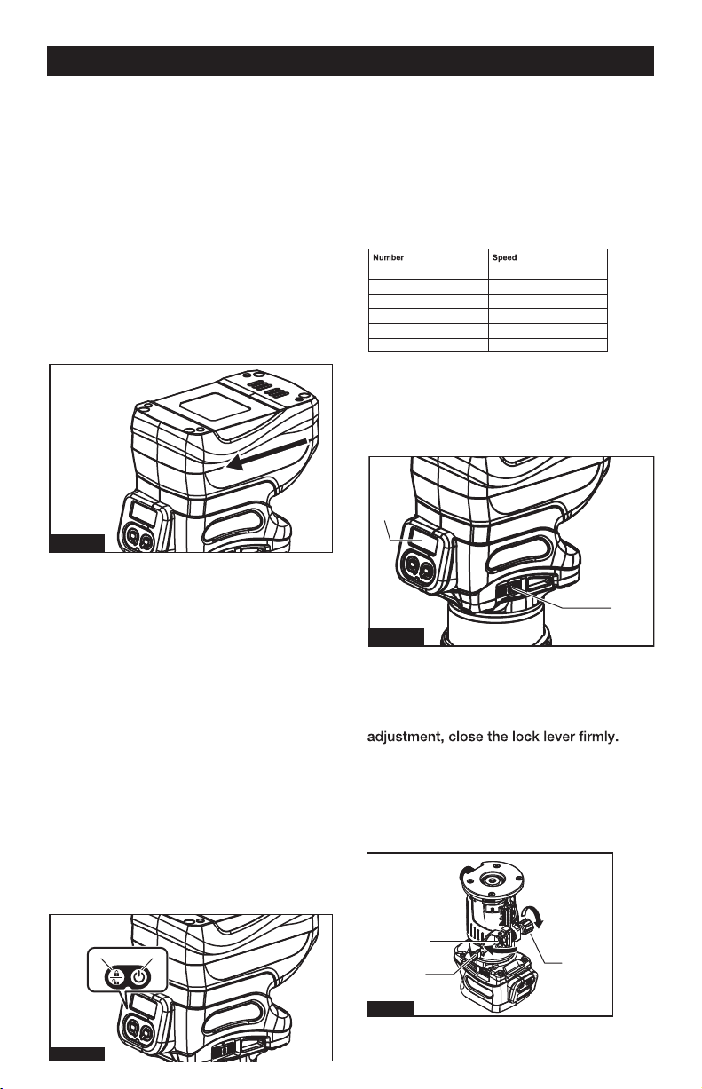
SPEED ADJUSTING DIAL
■Fig.4: 1. Speed adjusting dial
2. Digital display
NOTICE: When changing the speed dial
The digital display allows for accurate and
consistent speed adjustment.
from “6” to “1”, turn the dial counterclock-
wise. Do not turn the dial clockwise forcibly.
ADJUSTING CUTTING DEPTH
To adjust the cutting depth, open the lock
lever, then move the tool base up or down
by turning the adjusting screw. After the
■Fig.5: 1. Lock lever
2. Adjusting screw
3. Hex nut
NOTICE: If the tool is not secured after
closing the lock lever, tighten the hex nut,
and then close the lock lever.
TO ATTACH THE BATTERY PACK
1. Make sure that the router tool is turned
off.
2. Align the raised rib on the battery pack
with the grooves on the bottom of the tool,
and then attach the battery pack to the
router.
SWITCH ACTION
■Fig.3: 1. Lock/unlock button
2. Start/stop button
NOTE: If the tool is left for 10 seconds
without any operation in the standby mode,
the tool automatically
goes off.
turns off and the lamp
NOTE: You can also stop and turn off the
tool by pressing the lock/unlock button
while the tool is operating.
Fig.2
21
Fig.3
1 10,000 min
-1
2 14,000 min
-1
3 18,000 min
-1
4 22,000 min
-1
5 26,000 min
-1
6 30,000 min
-1
1
2
Fig.4
2
1
3
Fig.5
OPERATION
NOTICE: When attaching the battery pack
to the tool, make sure that the raised plat
form on the pack aligns with the grooves on
the bottom of the tool and that the latches
snap properly into place. Improper assem-
bly of the battery pack can cause damage
to internal components.
To turn on the tool, press the lock/unlock
button. The tool turns into the standby mode.
To start the tool, press the start/stop button
in the standby mode.
To stop the tool, press the start/stop button
again. The tool turns into the standby mode.
To turn off the tool, press the lock/unlock
button in the standby mode.
The rotation speed of the tool can be
changed by turning the speed adjusting
dial. The table below shows the number on
the dial and the corresponding rotation
speed.

Page 7
OPERATION
USING THE TOOL WITH THE ROUTER
BASE
Set the tool base on the workpiece without
the trimmer bit making any contact. Turn
the tool on and wait until the bit attains full
speed. Move the tool forward over the
while moving the tool.
When cutting the edge, be sure to keep the
workpiece surface on the left side of the
trimmer bit in the feed direction.
1
Fig.7
INSTALLING OR REMOVING ROUTER BIT
NOTICE: Do not tighten the collet nut
without inserting the bit. The collet cone
may break.
Insert the trimmer bit all the way into the
collet cone. Press the shaft lock and tighten
the collet nut with the wrench.
■Fig.6: 1. Shaft lock
■
Fig.8:
DUST HOOD INSTALLATION
1. Dust hood
2. Thumb screw
3. Router base
2. Loosen
3. Tighten
4. Wrench
5. Collet nut
NOTE: The shaft lock may not return to the
original position when you tighten the collet
nut at the installation of the trimmer bit. The
shaft lock returns to the original position
when you start the tool.
INSTALLING OR REMOVING THE ROUTER
BASE
2.
Close the lock lever.
3.
Attach the dust nozzle to the
trimmer
base, and then tighten the thumb screw.
To remove the base, follow the installation
procedure in reverse.
1
2
3
4
5
Fig.6
Fig.8
1. Open the lock lever of the trimmer base,
then insert the tool into the trimmer base
and align the groove on the tool with the
protrusion on the trimmer base.
1. Locate dust hood.
2. As shown in above diagram, place hood to
the bottom right until the holes line up.
3. Insert and tighten thumb screw.
4. Check to ensure attachment is secure, then
attach a 1 1/4” vacuum hose (not included).
1
2
3
■Fig.7: 1. Lock lever
CAUTION: When using the tool with the trim
mer base, be sure to install the dust nozzle
on the router base.

Page 8
OPERATION
NOTE: Before cutting on the actual
workpiece, it is recommended to make a
sample cut. The proper feed speed depends
on the trimmer bit size, the kind of workpiece,
and depth of cut. Moving the tool forward too
fast may cause a poor quality of cut, or cause
damage to the bit or motor.
Moving the tool forward too slowly may
burn and mar the cutting surface. When
using the trimmer shoe, the straight guide,
or the trimmer guide, be sure to keep it on
the right side in the feed direction. This will
help to keep it flush with the side of the
workpiece.
NOTICE: Since excessive cutting may
cause overload of the motor or difficulty in
controlling the tool, the depth of cut should
not be more than 3 mm at a pass when
cutting grooves. When you wish to cut
grooves more than 3 mm deep, make sever-
al passes with progressively deeper bit
settings.
USING THE STRAIGHT GUIDE
1. Assemble the straight guide with the bolt
and the wing nut.
2. Attach the straight guide to the trimmer
base with the clamp screw.
3. Loosen the wing nut on the straight guide
and adjust the distance between the bit and
the straight guide. At the desired distance,
tighten the wing nut.
■Fig.9:
1.Bolt
2.Guide plate
3.Straight guide
4.Wing nut
4. Move the tool with the straight guide
If the distance (A) between the side of the
workpiece and the cutting position is too
wide for the straight guide, or if the side of
the workpiece is not straight, the straight
clamp a straight board to the workpiece
and use it as a guide against the trimmer
base. Feed the tool in the direction of the
arrow.
USING THE STRAIGHT GUIDE FOR
CIRCULAR WORK
For circular work, assemble the straight
and maximum radius of circles to be cut
(distance between the center of circle and
the center of bit) are as follows:
• Minimum: 2-1/2"
• Maximum: 8-11/16"
For cutting circles between 2-1/2" and 4-5/8"
in radius.
■ Fig. 10:
Fig.9
Fig.10
1
2
3
4
1
2
3
4
5
1. Wing nut
2. Guide plate
3. Straight guide
4. Center hole
5. Bolt

Page 9
OPERATION
USING THE ROLLER GUIDE
For cutting circles between 4-5/8" and
8-11/16" in radius.
■ Fig. 11:
NOTE:
• Circles between 6- 3/4" and 7- 5/16" in
radius cannot be cut using this guide (because
center hole (4) is blocked).
• Align the center hole in the straight guide
with the center of the circle to be cut. Drive a
nail less than 1/4" in diameter into the center
hole to secure the straight guide. Pivot the tool
around the nail in clockwise direction.
■ Fig. 12:
Fig.12
Fig.13
■ (Fig. 13)The trimmer guide allows for
trimming the curved side like veneers for
furniture by moving the guide roller along the
side of the workpiece.
1. Loosen the clamp screw, then install the
trimmer guide on the trimmer base, and
then tighten the clamp screw.
2. Loosen the clamp screw and adjust the
distance between the trimmer bit and the
trimmer guide by turning the adjusting screw
(1mm per turn). At the desired distance,
tighten the clamp screw to secure the trimmer
guide.
■Fig.14: 1. Adjusting screw
2. Clamp screw
3. Move the tool with the guide roller riding
the side of the workpiece.
1
2
Fig.14
1
2
3
1. Nail
2. Center hole
3. Straight guide
1. Wing nut
2. Guide plate
3. Straight guide
4. Center hole
5. Bolt
Fig.11
1
2
3
4
5

Page 10
WARNING:
Before cleaning or
performing any maintenance, the tool should
be unplugged from the power supply.
WARNING:
If the supply cord
is damaged, it must be replaced by a
specially prepared cord available through
the service organization.
GENERAL MAINTENANCE
2. Inspect the screws periodically. If the
screws loosen, tighten them immediately, to
avoid serious accident.
3. Clean all parts of the tool; clean dust and
debris from vents. Keep the tool clean, dry
and free of oil or grease.
4. Avoid using solvents when cleaning
plastic parts. Most plastics are susceptible
to damage from various types of commercial
solvents and may be damaged by their use.
Use clean cloths and mild soap to remove
dirt, dust, etc.
LUBRICATION
All of the bearings in this product are
lubricated with a sufficient amount of high
grade lubricant for the life of the unit under
normal operating conditions. Therefore, no
further lubrication is required.
MAINTENANCE
Using compressed air may be the most
effective cleaning method. Always wear
safety goggles when cleaning tools with
compressed air. Periodic maintenance
allows for long life and trouble-free opertion.
A cleaning, lubrication and maintenance
schedule should be maintained.
1.Avoid dropping or otherwise causing
impact to the tool and keep it from oil and
grease.

Page 11
PARTS LIST
No. Description Qty. No. Description Qty.
1 Screws ST4×16 8 19 Aluminum housing 1
2 Label 1 20 Knob 1
3 Left housing 1 21 Spring 1
4 Battery clip assembly 1 22 Pin 1
5 PCBA 1 23 Chuck 1
6 Switch Label 1 24 Nut 1
7 Switch 1 25 Knob 1
8 Display cover 1 26 Shim 6.5x12x1 1
9 Digital display 1 27 Pin 4×4 1
10 LED PCBA 1 28 Gear 1
11 Right housing 1 29 Cam base 1
12 Label 1 30 Aluminum base 1
13 Stator 1 31 Knob 1
14 Bearing 1 32 Rubber block 1
15 Rotor 1 33 Locking handle 1
16 Bearing 1 34 Nut M5 1
17 Wave washer 1
35 Screws M4×10 4
18 Sleeve 1 36 Base plate 1
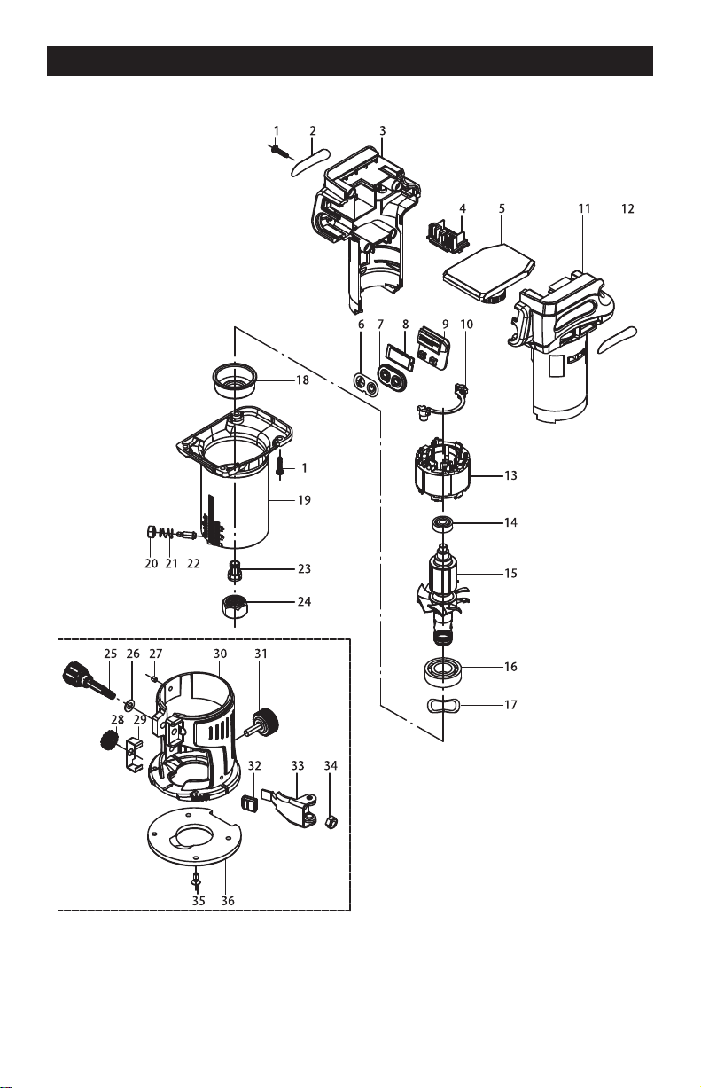
Page 12
SCHEMATIC DRAWING

SAVE YOUR RECEIPTS
THIS WARRANTY IS VOID WITHOUT THEM
20V BRUSHLESS DIGITAL COMPACT ROUTER
WARRANTY
90-DAY MONEY BACK GUARANTEE:
This MASTERFORCE
®
.eetnarauG kcaB yenoM YAD-09 ruo seirrac loot rewop dnarb
If you are not completely satisfied with your MASTERFORCE
®
brand power tool for
any reason within ninety (90) days from the date of purchase, return the tool with your
original receipt to any MENARDS
®
retail store, and we will provide you a refund – no
questions asked.
3-YEAR LIMITED WARRANTY:
This MASTERFORCE
®
brand power tool carries our famous No Hassle 3-Year Limited
Warranty to the original purchaser. If, during normal use, this MASTERFORCE
®
power
tool breaks or fails due to a defect in material or workmanship within three (3) years from
the date of original purchase, simply bring this tool with the original sales receipt back
to your nearest MENARDS
®
retail store. At its discretion, MASTERFORCE
®
agrees
to have the tool or any defective part(s) repaired or replaced with the same or similar
MASTERFORCE
®
product or part free of charge, within the stated warranty period,
when returned by the original purchaser with original sales receipt. Not withstanding
the foregoing, this limited warranty does not cover any damage that has resulted from
abuse or misuse
of the Merchandise. This warranty: (1) excludes expendable parts
including but not limited to blades, brushes, belts, bits, light bulbs, and/or batteries; (2)
shall be void if this tool is used for commercial and/or rental purposes; and (3) does not
cover any losses, injuries to persons/property or costs. This warranty does give you
specific legal rights and you may have other rights, which vary from state to state. Be
careful, tools are dangerous if improperly used or maintained. Seller’s employees are
not qualified to advise you on the use of this Merchandise. Any oral representation(s)
made will not be binding on seller or its employees. The rights under this limited
warranty are to the original purchaser of the Merchandise and may not be transferred
to any subsequent owner. This limited warranty is in lieu of all warranties, expressed
or implied including warranties or merchantability and fitness for a particular purpose.
Seller shall not be liable for any special, incidental, or consequential damages. The
sole exclusive remedy against the seller will be for the replacement of any defects
as provided herein, as long as the seller is willing or able to replace this product or is
willing to refund the purchase price as provided
above. For insurance purposes, seller
is not allowed to demonstrate any of these power tools for you.
For questions / comments, technical assistance or repair parts –
Please Call Toll Free at: 1-866-915-8626. (M-F 9am – 5pm)
page 13

© 2021 Menard, Inc., Eau Claire, WI 54703 05/2021