Loading ...
Loading ...
Loading ...
J Jation
INSTAI,,,,,,,,,,I,,,,,,,,,,INGTHE SUPPORTSYSTEB
[] [] [] [] [] [] [] [] [] [] [] [] [] [] [] [] [] [] [] [] [] []
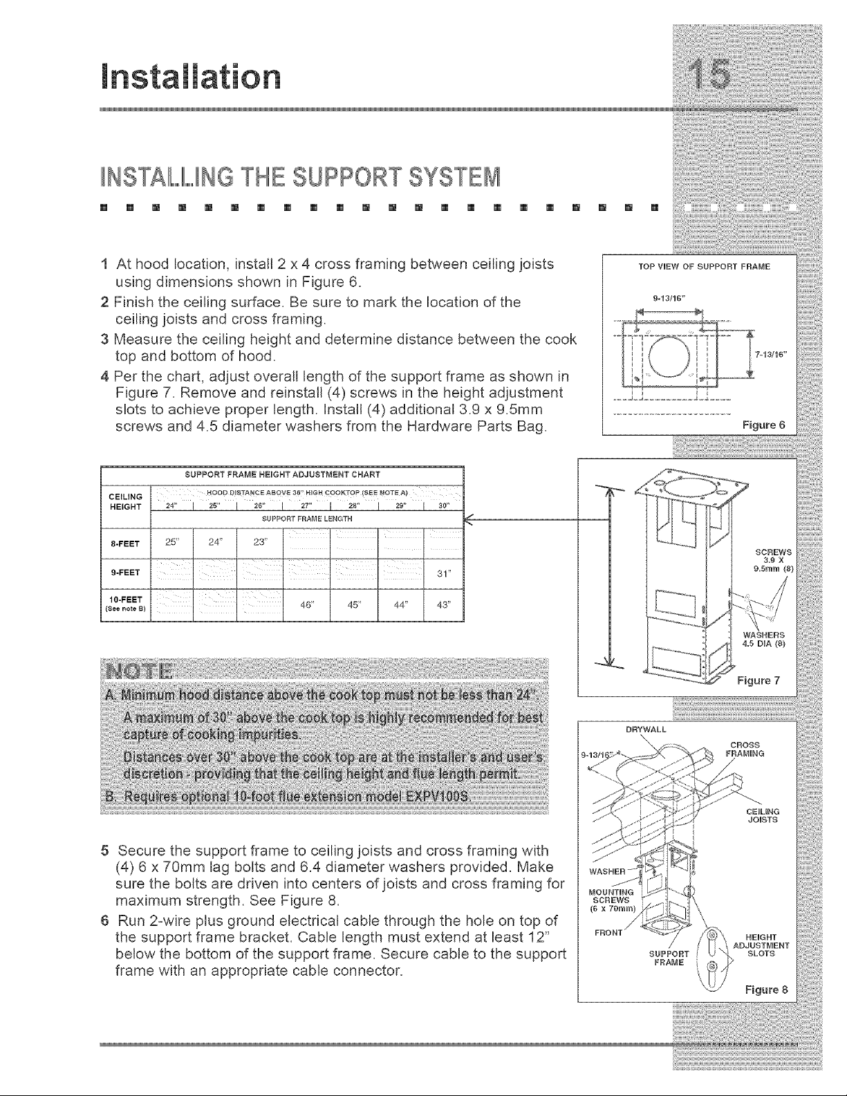
1 At hood location, install 2 x 4 cross framing between ceiling joists
using dimensions shown in Figure 6.
2 Finish the ceiling surface. Be sure to mark the location of the
ceiling joists and cross framing.
3 Measure the ceiling height and determine distance between the cook
top and bottom of hood.
4 Per the chart, adjust overall length of the support frame as shown in
Figure 7. Remove and reinstall (4) screws in the height adjustment
slots to achieve proper length. Install (4) additional 3.9 x 9.5mm
screws and 4.5 diameter washers from the Hardware Parts Bag.
CEILING
HEIGHT
8-FEET
9-FEET
10-FEET
(See note B)
SUPPORT FRAME HEIGHT ADJUSTMENT CHART
HOOD DISTAN¢ E ABOVE 3_' HiGH COOKTOP (SEE _OTE A)
24" J 25" J 26" J 27" I 28" I 29" I 30"
SUPPORT FRAME LENGTH
k _ F
25" 24" 23"
F k F
31"
I I
, , 46" 45" 44" 43"
DRYWALL
\
5 Secure the support frame to ceiling joists and cross framing with
(4) 6 x 70mm lag bolts and 6.4 diameter washers provided. Make
sure the bolts are driven into centers of joists and cross framing for
maximum strength. See Figure 8.
6 Run 2-wire plus ground electrical cable through the hole on top of
the support frame bracket. Cable length must extend at least 12"
below the bottom of the support frame. Secure cable to the support
frame with an appropriate cable connector.
Loading ...
Loading ...
Loading ...