Use E_ Care Guide
lnstaWWation Instructions
Ve n _ 1_o o d
J
READ AND SAVE THESE INSTRUCTIONS
[] [] [] [] [] [] [] [] [] [] [] [] [] [] [] [] [] [] [] [] [] []
Read all instructions before installing the hood.
For your safety, please read and observe all safety instructions. This guide will
help you anticipate all installation connections.
[] [] [] [] [] [] [] [] [] [] [] [] [] [] []
For toll-free telephone support in the U.S. and Canada:
1=877= 4ELECTROLUX (1=877=435=3287)
For online support and Intemet product information:
www.electro_uxusa.com
[] [] [] [] [] []
@2006 Electrolux Home Products, Inc,
Post Office Box 212378, Augusta, Georgia 30917, USA
Al! rights reserve& Printed in the USA
J
TABIIII,,,,,,,,,,EOF CONTENTS
[] [] [] [] [] [] [] [] [] [] [] [] [] [] [] [] [] [] [] [] [] []
FindingInformation..............................................2
PleaseReadAndSaveThisGuide...................2
MakeA RecordForQuickReference................2
Questions...........................................................2
TableOfContents..............................................3
Safety.....................................................................4
ImportantSafetyInstructions.............................4
GeneralPrecautions..........................................5
Getting Started......................................................8
OperatingYourHood.........................................8
Careand Cleaning...............................................11
Cleaningthe FiltersandHood..........................11
Installation...........................................................12
InstallationPlanning.........................................12
VarifyingPackageContents.............................13
Installingthe Ductwork.....................................14
Installingthe SupportSystem..........................15
Connectingthe DecorativeFlue......................16
Installingthe DuctCollar..................................16
Mountingthe Hoodto SupportFrame.............17
Installingthe Electrical.....................................17
Connectingthe Ductwork.................................18
Replacingthe BottomTrim ..............................18
Installingthe Filters..........................................19
Troubleshooting ................................................20
IfServiceis Required.......................................20
TroubleshootingGuide.....................................21
EnergySavingTips..........................................22
WarrantyInformation.........................................24
Safety Precautions
Do not attempt to install or operate your unit untie you have read the safety
precautions in this manual. Safety items throughout this manual are labeled with a
Warning or Caution based on the risk type,
Definitions
Z_ This is the safety alert symbol. It is used to alert you to potential personal injury
hazards. Obey all safety messages that follow this symbol to avoid possible injury
or death,
i¸iiii_iii!i_i_iil,i_iii!i_i_iil,i_iiiiiiiiiiiil_i__!!_!_ii!_i_!_!iiii_i_i!!i:i_i!_!!_!_i_!_:i_!_!i_i!_!_iiii_i_i!_!i_i!!!i_i!_!i_i!!!i_i!_!i_i!!!i_i!_!i_i!!!i_i!_!i_i!!!i_i{_i_i!i!!_!i_i_i!!_!_iii!i!_i!_ii_ii_!iii!!ii,!iiii_ilJ!iiii!i!ili!i!ili!i_ii!il,i_!i!,i_!i!,i_!i!,i_!i!,i_iiiii!i!iiiiiiiiii!iiiii:ii_i_i_i!i!iiii'i!!iiiii:ii!i:iiii:ii!i:iiii:ii!i:iiii:!i!ili'i_!_i!i!i!ii_i:iiiiii_iii!_iiiii_iiii!ii!,!:ii_!i:!:!i:!_!_!i_!i_i_ii!ii!i!!ii!ii!iii_i_J_:!i!_i_i_ii!ii!_!_!i!ii_i_ii_!_ii!i_i_i_:i_i_:i_i_:i_i%!_i_i!:!_!_ii!_i,_i_z!_!_z_!_i!_!_ii_!_!_!iii_ii!_ii!_ii!_i!_i_i_i_!_!_i!i!!_i_!_i_!_¸i_i_iii!!_!i_i_i_i!i_i_!i_!_!i_!_i_!_!i!_!_i%!_!_!_i!_!_i_i_!_ii_ii_ii_ii_!J_iii!_!_i_ii_i¸ii_i¸_!_!_ii!_!i_i!i!_ii!i!_ii!i!_ii!i!_ii!_!_!i!i!!_i_i_i_i_i_i_i_i!_i_i!i_i_!!i:ii_i!ii_i_!_!:i_ii_ii!:i_ii_ii!:i_ii_ii!:i_ii_ii!:i_ii_ii!:i_ii_ii!_!i_!!_!!_i_i_!:!_!i!:!,!_!:!iii_i,iiiiiiiiiiii!i!iiii!_i_iii_i!_i_i!i_i!_!_i_i_i!ii_i_i_ii!iiii_i¸iii!iii'Jiiii_ilili!i_iii!i_iii!i_iii!i_iii!i_iii!iii!iilliiiii_i!i_i_
SAFETY PRECAUTIONS
[] [] [] [] [] [] [] [] [] [] [] [] [] [] [] [] [] [] [] [] m []
ORERATIHG YOUR HOOD
[] [] [] [] [] [] [] [] [] [] [] [] [] [] [] [] [] [] [] [] [] []
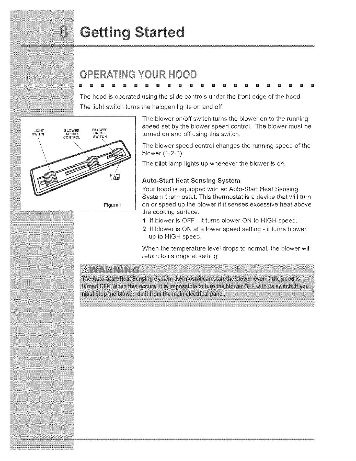
The hood is operated using the slide controls under the front edge of the hood.
The light switch turns the halogen lights on and off.
PHLOT
LAMP
Figure 1
BLOWER
ON/OFF
SWHTCR
The blower on/off switch turns the blower on to the running
speed set by the blower speed control. The blower must be
turned on and off using this switch.
The blower speed control changes the running speed of the
blower (1-2-3).
The pilot lamp lights up whenever the blower is on.
Auto-Start Heat Sensing System
Your hood is equipped with an Auto-Start Heat Sensing
System thermostat. This thermostat is a device that will turn
on or speed up the blower if it senses excessive heat above
the cooking surface.
1 If blower is OFF - it turns blower ON to HIGH speed.
2 If blower is ON at a lower speed setting - it turns blower
up to HiGH speed.
When the temperature level drops to normal, the blower will
return to its original setting.
HALOGEN BULBS
[] [] [] [] [] [] [] [] [] [] [] [] [] [] [] [] [] [] []
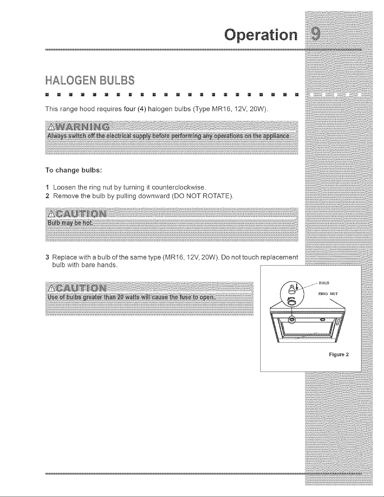
This range hood requires four (4) halogen bulbs (Type MR16, 12V, 20W).
[] []
To change bulbs:
1 Loosen the ring nut by turning it counterclockwise.
2 Remove the bulb by pulling downward (DO NOT ROTATE).
3 Replace with a bulb of the same type (MR16, 12V, 20W). Do not touch replacement
bulb with bare hands.
Figure 2
FUSE REPIIII,,,,,,,,,ACEMENT
[] [] [] [] [] [] [] [] [] [] [] [] [] [] [] [] [] [] [] [] []
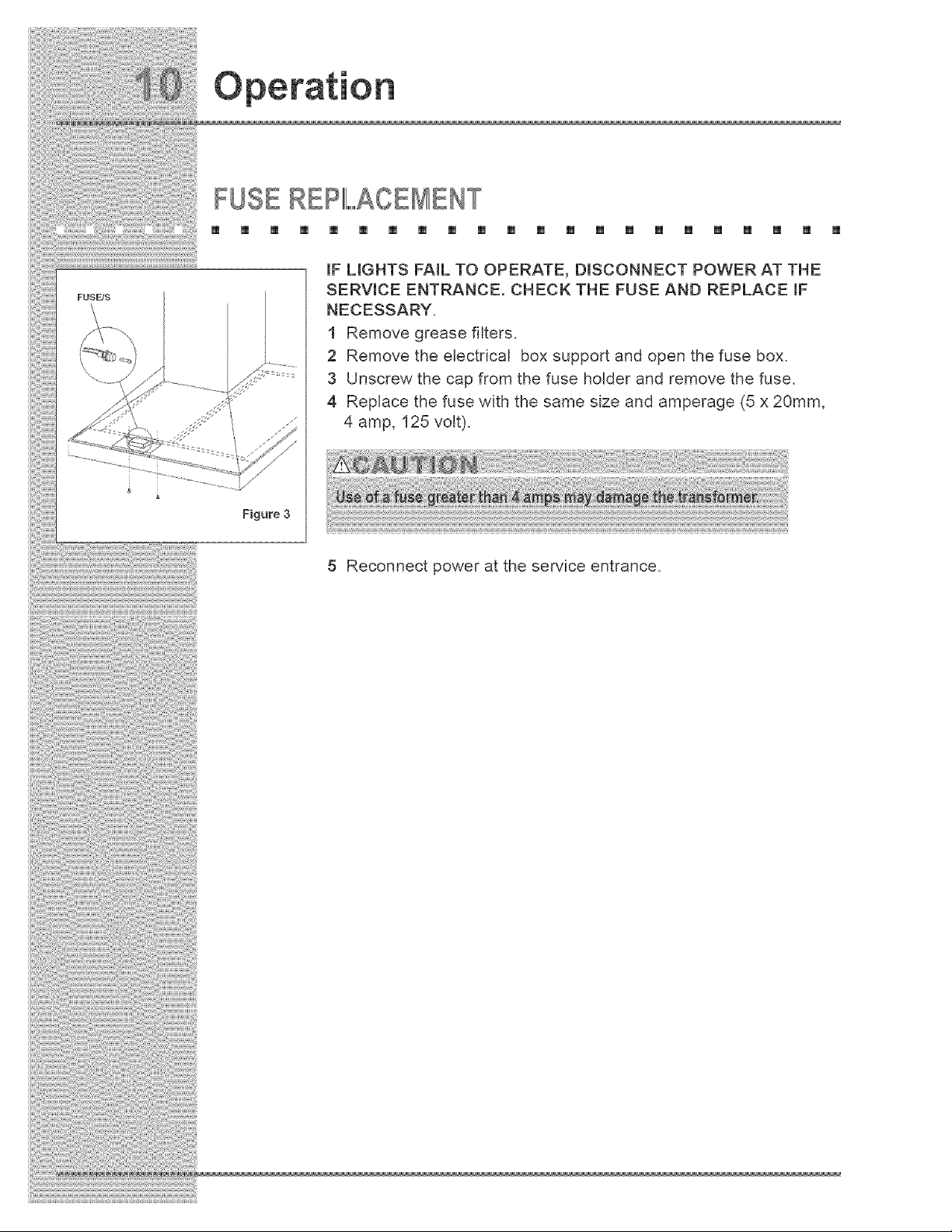
mFUGHTS FAiL TO OPERATE, DmSCONNECT POWER AT THE
SERVICE ENTRANCE. CHECK THE FUSE AND REPLACE mF
NECESSARY.
1 Remove grease filters.
2 Remove the electrical box support and open the fuse box.
3 Unscrew the cap from the fuse holder and remove the fuse.
4 Replace the fuse with the same size and amperage (5 x 20mm,
4 amp, 125 volt).
Figure 3
5 Reconnect power at the service entrance.
Care an Cleanin
ClIII,EANINGTHE FIL,,,,RS AND HOOD
[] [] [] [] [] [] [] [] [] [] [] [] [] [] [] [] [] [] [] [] [] []
Proper maintenance of the Range Hood will assure proper performance of the unit,
Grease Filters
The grease fi_ters should be cleaned frequently. Use a warm detergent solution,
Grease filters are dishwasher safe,
See "INSTALL FILTERS" section for removal and installation instructions.
Hood Cleaning
Stainless steel is one of the easiest materials to keep clean. Occasional care will
help preserve its fine appearance.
Cleaning tips:
1 Hot water with soap or detergent is all that is usually needed.
2 Follow all cleaning by rinsing with clear water. Wipe dry with a clean, soft cloth
to avoid water marks.
3 For discolorations or deposits that persist, use a non-scratching household
cleanser or stainless steel polishing powder with a little water and a soft cloth.
4 For stubborn cases, use a plastic scouring pad or soft bristle brush together
with cleanser and water. Rub lightly in direction of polishing lines or "grain" of the
stainless finish. Avoid using too much pressure which may mar the surface.
5 DO NOT allow deposits to remain for long periods of time.
6 DO NOT use ordinary steel wool or steel brushes. Small bits of steel may
adhere to the surface causing rust.
7 DO NOT allow salt solutions, disinfectants, bleaches, or cleaning compounds
to remain in contact with stainless steel for extended periods. Many of these
compounds contain chemicals which may be harmful. Rinse with water after
exposure and wipe dry with a clean cloth.
Painted surfaces should be cleaned with warm water and mild detergent only.
!
INSTAl,I,ATIONPLANNING
[] [] [] [] [] [] [] [] [] [] [] [] [] [] [] [] [] [] [] [] [] []
A qualified installer must complete the installation of this built-in appliance. Proper
installation is your responsibility.
Carefully check the location where the hood is to be installed. The hood should be
placed for convenient access. Make certain that electrical power can be provided
in the selected location.
Plan the installation so that all minimum clearances are met or exceeded.
Dimensions shown provide minimum clearances, unless otherwise noted.
Make certain that you have everything necessary to ensure a proper
installation before proceeding.

VERIFY PACKAGE CONTENTS
[] [] [] [] [] [] [] [] [] [] [] [] [] [] []
Unpack hood and check contents.
You should receive:
1 - Hood
1 - Decorative Flue Assembly
1 - Support Frame
1 - Duct Collar
1 - Parts Bag containing:
8 - Washers ® 6.4
4 - Washers e 4.5
4 - Lag Bolts
8 - Mounting Screws (3.9 X 9.5mm Pan Head)
4 - Hex Nuts
1 - Installation Instructions
2 - Warranty Cards
[] [] [] []
4 REX NUTS
DECORATIVE
FLUE
SUPPORT
FRAME
8 WASHERS
_6.4
4 WASHERS
e4.5
8 MOUNTING SCREWS
(3.9 × 9.5ram Pan Head)
[] [] []
4 Lag Bolts
(6x7Omm)
DUCT COLLAR
Figure 4
!
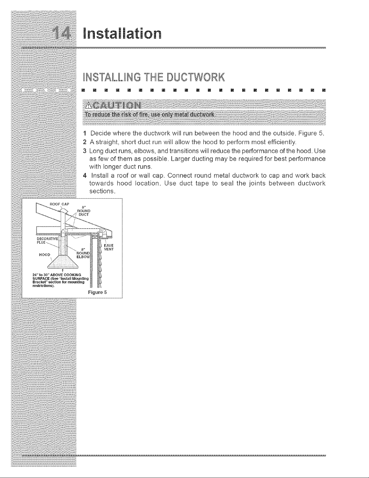
INSTALLINGTHE DUCTWORK
[] [] [] [] [] [] [] [] [] [] [] [] [] [] [] [] [] [] [] [] [] []
1 Decide where the ductwork will run between the hood and the outside. Figure 5.
2 A straight, short duct run will allow the hood to perform most efficiently.
3 Long duct runs, elbows, and transitions will reduce the performance of the hood. Use
as few of them as possible. Larger ducting may be required for best performance
with longer duct runs.
4 Install a roof or wall cap. Connect round metal ductwork to cap and work back
towards hood location. Use duct tape to seal the joints between ductwork
sections.
ROOF CAP
\ 8"
ROUND
DUCT
DECORATIVE
FLUE_
HOOD
24" to 30" ABOVE COOKING
SURFACE (See "Install Mounting
Bracket" section for mounting
restrictions).
Figure 5
J Jation
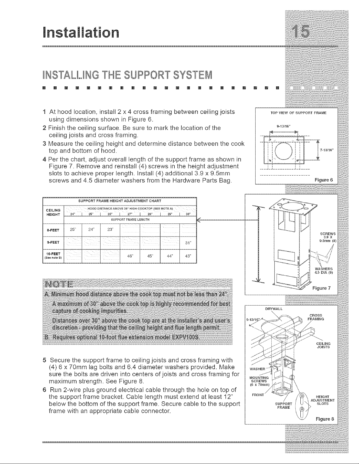
INSTAI,,,,,,,,,,I,,,,,,,,,,INGTHE SUPPORTSYSTEB
[] [] [] [] [] [] [] [] [] [] [] [] [] [] [] [] [] [] [] [] [] []
1 At hood location, install 2 x 4 cross framing between ceiling joists
using dimensions shown in Figure 6.
2 Finish the ceiling surface. Be sure to mark the location of the
ceiling joists and cross framing.
3 Measure the ceiling height and determine distance between the cook
top and bottom of hood.
4 Per the chart, adjust overall length of the support frame as shown in
Figure 7. Remove and reinstall (4) screws in the height adjustment
slots to achieve proper length. Install (4) additional 3.9 x 9.5mm
screws and 4.5 diameter washers from the Hardware Parts Bag.
CEILING
HEIGHT
8-FEET
9-FEET
10-FEET
(See note B)
SUPPORT FRAME HEIGHT ADJUSTMENT CHART
HOOD DISTAN¢ E ABOVE 3_' HiGH COOKTOP (SEE _OTE A)
24" J 25" J 26" J 27" I 28" I 29" I 30"
SUPPORT FRAME LENGTH
k _ F
25" 24" 23"
F k F
31"
I I
, , 46" 45" 44" 43"
DRYWALL
\
5 Secure the support frame to ceiling joists and cross framing with
(4) 6 x 70mm lag bolts and 6.4 diameter washers provided. Make
sure the bolts are driven into centers of joists and cross framing for
maximum strength. See Figure 8.
6 Run 2-wire plus ground electrical cable through the hole on top of
the support frame bracket. Cable length must extend at least 12"
below the bottom of the support frame. Secure cable to the support
frame with an appropriate cable connector.
!
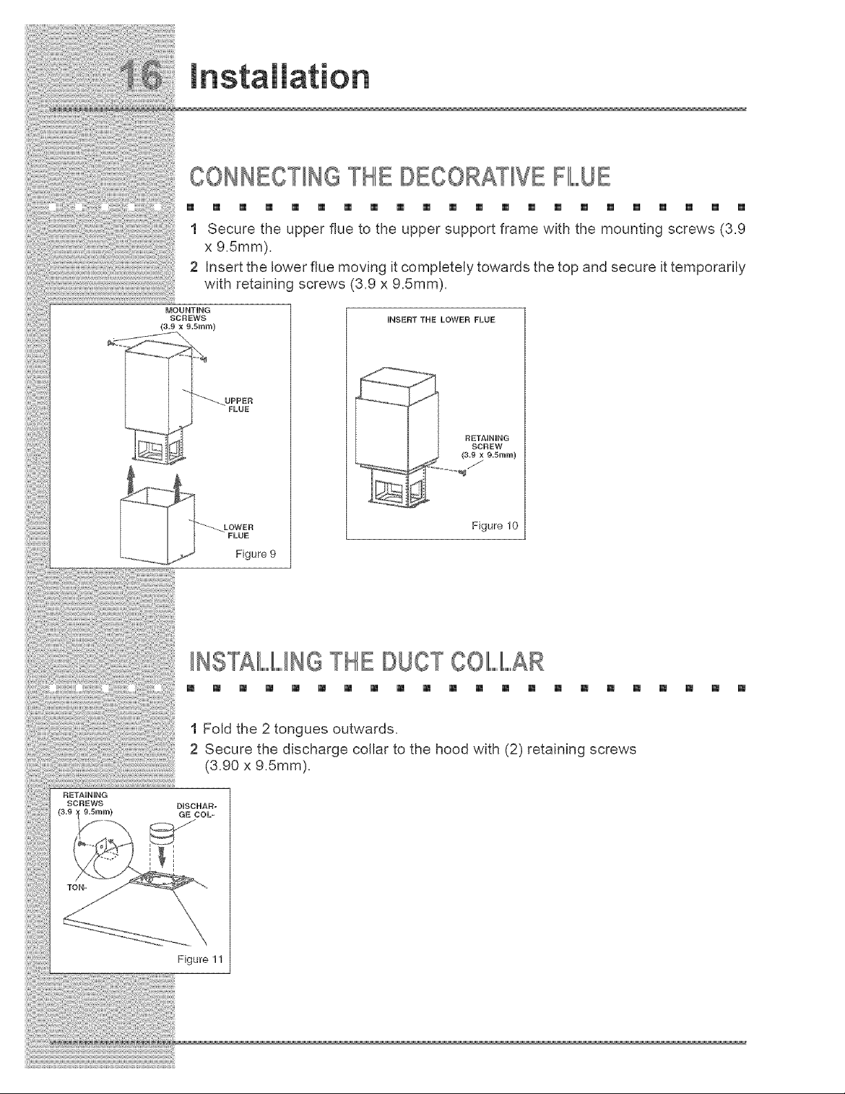
CONNECTINGTHE DECORATIVEFLUE
[] [] [] [] [] [] [] [] [] [] [] [] [] [] [] [] [] [] [] [] [] []
1 Secure the upper flue to the upper support frame with the mounting screws (3.9
x 9.5mm).
2 Insert the bower flue moving it completely towards the top and secure it temporarily
with retaining screws (3.9 x 9.5mm).
MOUNTING
SCREWS
(s.9 xg.5mm)
UPPER
FLUE
iNSERT THE LOWER FLUE
Figure 10
INSTAL,LINGTHE DUCTCOIIII,,,,,,,,,,I,,,,,,,,,,AR
m [] [] [] [] [] [] [] [] [] [] [] [] [] [] [] [] [] [] [] [] []
1 Fold the 2 tongues outwards.
2 Secure the discharge collar to the hood with (2) retaining screws
(3.90 x 9.5mm).
RETAiNiNG
SCREWS DISCHAR-
Figure 11
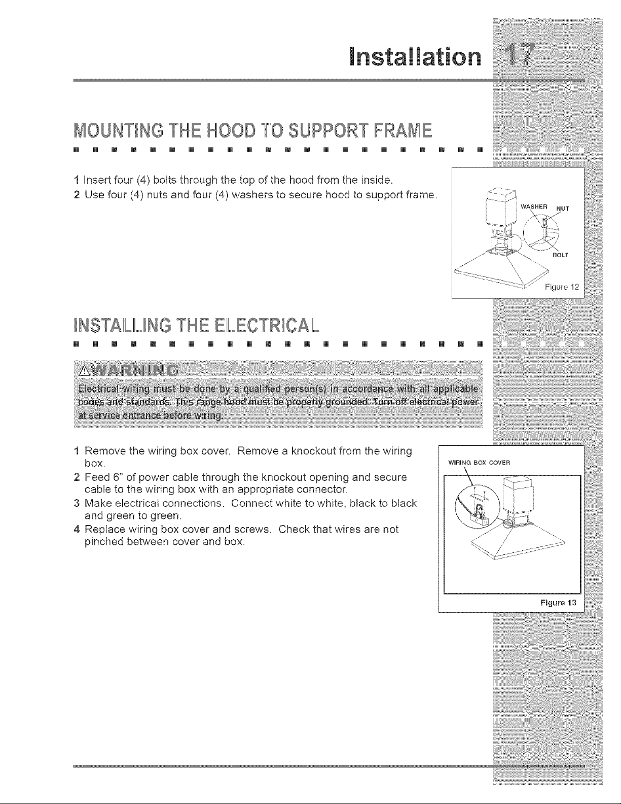
MOUNTINGTHE HOODTO SUPPORT FRAME
[] [] [] [] [] [] [] [] [] [] [] [] [] [] [] [] [] [] []
1 Insert four (4) bolts through the top of the hood from the inside,
2 Use four (4) nuts and four (4) washers to secure hood to support frame.
[] []
r
INSTAL,LINGTHE EIIII,,,,,,,,,,ECTRICAIIII..........
[] [] [] [] [] [] [] [] [] [] [] [] [] [] [] [] [] [] [] [] [] []
1 Remove the wiring box cover. Remove a knockout from the wiring
box.
2 Feed 6" of power cable through the knockout opening and secure
cable to the wiring box with an appropriate connector.
3 Make electrical connections. Connect white to white, black to black
and green to green.
4 Replace wiring box cover and screws. Check that wires are not
pinched between cover and box.
WiRiNG BOX COVER
Figure 13
[
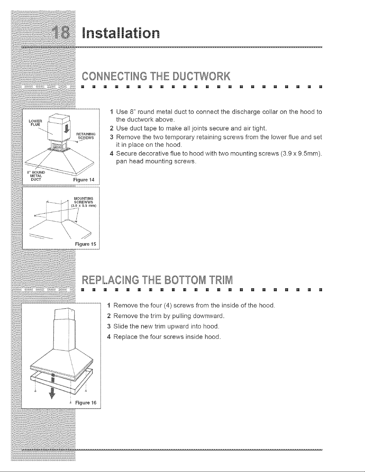
CONNECTINGTHE DUCTWORK
[] [] [] [] [] [] [] [] [] [] [] [] [] [] [] [] [] [] [] [] [] []
LOWER
FLUE
8" ROUND
METAL
DUCT
RETAINING
SCREWS
Figure 14
1 Use 8" round metal duct to connect the discharge collar on the hood to
the ductwork above,
2 Use duct tape to make all joints secure and air tight,
3 Remove the two temporary retaining screws from the lower flue and set
it in place on the hood,
4 Secure decorative flue to hood with two mounting screws (3,9 x 9,5mm),
pan head mounting screws.
MOUNTING
Figure 15
R IIII,AClNGTHEBO TRIM
[] [] [] [] [] [] [] [] [] [] [] [] [] [] [] [] [] [] [] [] [] []
1 Remove the four (4) screws from the inside of the hood.
2 Remove the trim by pulling downward.
3 Slide the new trim upward into hood.
4 Replace the four screws inside hood.
Figure 16
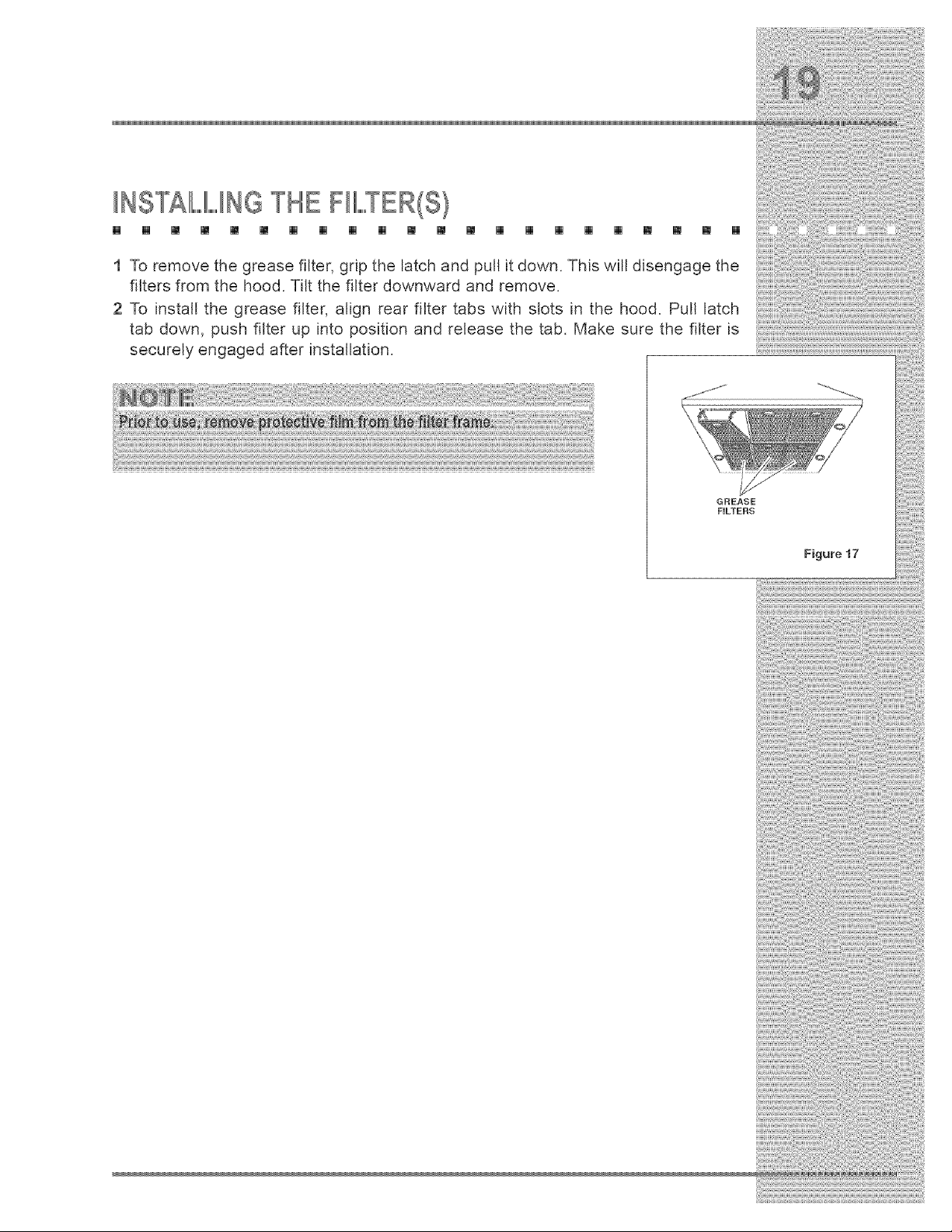
INSTALLINGTHE FIL,,,,,,R(S)
[] [] [] [] [] [] [] [] [] [] [] [] [] [] [] [] [] [] [] [] [] []
1 To remove the grease filter, grip the latch and pull it down. This will disengage the
filters from the hood. Tilt the filter downward and remove.
2 To install the grease filter, align rear filter tabs with slots in the hood. Pull latch
tab down, push filter up into position and release the tab. Make sure the filter is
securely engaged after installation.
ii¸ii'_iiii¸¸_ili!i{i¸¸_i_:(i!_i_'_!!i_¸_''_'_'_!i_¸¸¸_i!i!!@i_iii!,!ii!,!iiiiill¸I!II¸:!I_!_:!I:!{!¸:iii_i!ii_i!ii_i!!i:_i:_:_:_!i!_!ii_i_ii_ii_ii_ii_ii_ii!i_i_%_!!!!_ii_!_!_¸i!iil¸iii:!ii_?ii!i:iii:iii:iii:i!i!!i:i!i!!_!i_!_!!!!i_!iiii!!i¸I¸@!@%i_iiii_!_iii¸?iiiii!i:_ii:i:iii!:¸i!{i_i!:_ii_!iii!i!iii!:i_!i!ili!i_:_i!i_:_i{iiii!@ili!i_iiiii{{!!ii:@!i':_i!i':_!ii_i¸iiii:i:!:!iiiii_',_ii_iiii(_ii_ii_i!i_i¸I¸ili:i_i!!:i!i!:i!i!iiiiiiiii%iii_ii(i(ili@ii¸i¸I¸ii!_ii!i!({i_iii!i!ii!£1:_@!i!_i!i!_i!ii!iiiiii!i_iiii¸i_ili¸i_ili¸I
iliii_!_!_i!_i!_i_!E!i!_i_i_i:ii!i!_ii_i!iii:_:_!i!!!_!i!!!!!_!_!_i_:i_i:i_!_i!_i_!_i_i!_!_ii!i_i_i_!:i_i_!:i_ii_iii_i_ii_!_!J_i_i_iii!i:_!_i!_i_!_i_!_i_!@!:!_i!i£{{_i_!_!_ii_!_!_ii_!_i_i_i_(_ii!i_!_ii_@:@_i_i_!_!_!_ii__i_ii_ii_ili_ii_ili_i!i_iiii_!ii_i_@@i!:_iii_i_i!_!_!_!_!!i:i_@_!_@_ii_!:i_i_!_i_i_!_!_i_!i:_!i_i_!_!!:_!_i__i_i::_@ii_i_i!_!_:_i_ii!_i_(@_!@_i_i!i!_i_!!!i_i@_ii:iJi!:i:_i!_!_(_!:!i_!_!_!i!_{_i!i_i_i_i_::i_::i_::i_!!!:!_i!!:_:_!ii!_ii!iii_!!_!_!i!i_
i i!ii!i i!ii!:!ii!ii!ii!ii!ii!ii!ii!ii!ii!iiiiiii i iii!i !ili i!iiiiii
GREASE
FILTERS
Figure 17

First, review the recommended checks listed in the Troubleshooting Guide.
Then, be certain that the appliance has been installed properly and is being
operated correctly. Familiarize yourself with the warranty terms and conditions
listed in the Warranty section.
If the above checks have been completed and the problem has not yet been
remedied, contact the dealer where you purchased the unit. State the Model and
Serial number and explain the problem. The Model and Serial number plate is
located inside the unit at upper right hand corner.
If you do not know the name of the selling dealer or local service company, you
can check online at www.eJectro_uxusa.com.
m m
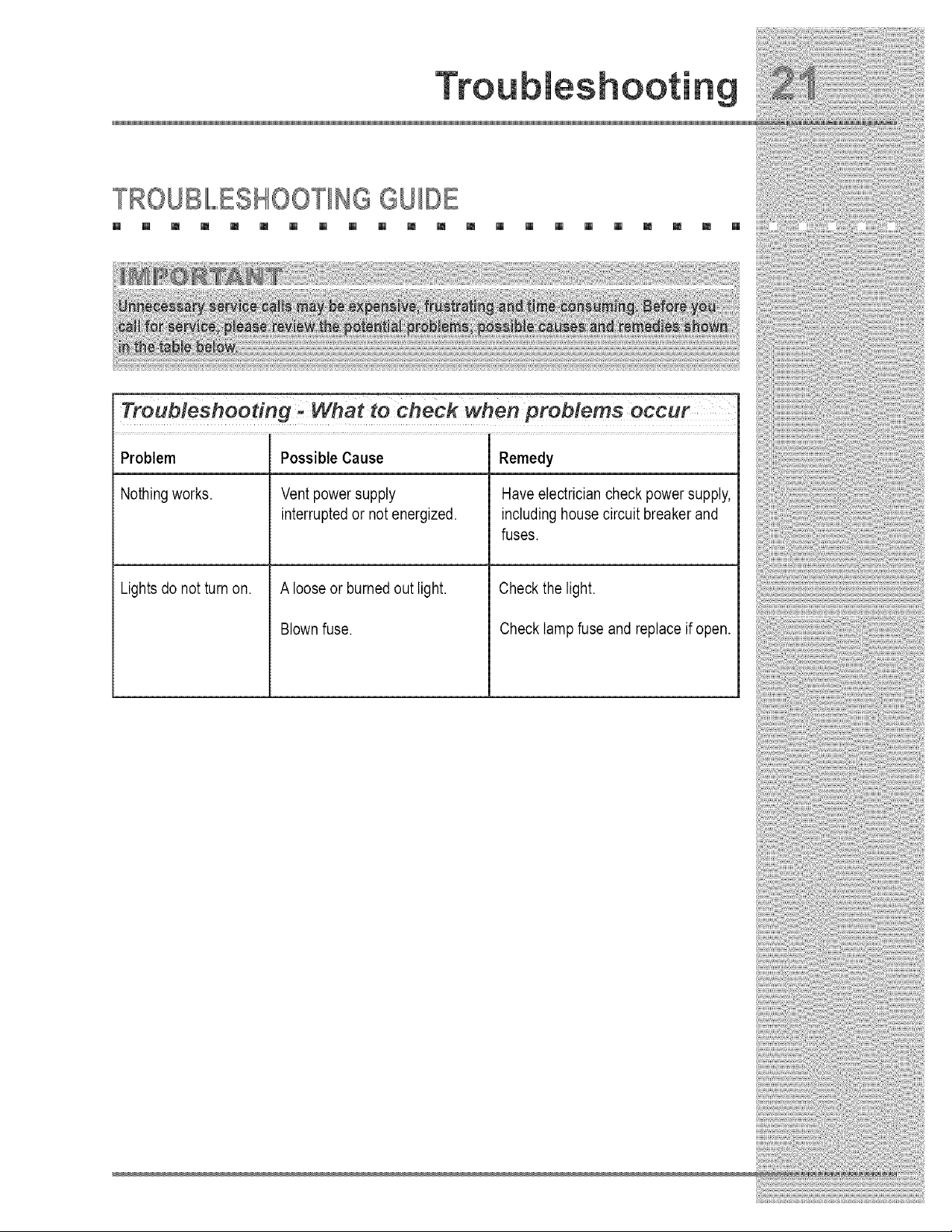
TROUBIIII,,,,,,,,,,HOOTING GUIDE
[] [] m m [] [] [] [] [] [] m m m [] [] [] [] [] m m [] []
Troub/eshoedng . What to check when preblems occur
Problem Remedy
Nothing works. Have electrician check power supply,
includinghouse circuit breaker and
fuses.
Lights do not turn on.
Possible Cause
Vent power supply
interruptedor not energized.
A loose or burned out light.
Blown fuse.
Check the light.
Check lamp fuse and replace if open.
1 Do not operate the blower at a speed that is higher than necessary to
remove the cooking exhaust. Running at excessive speeds removes more air
from the inside of the house that must be replaced by outside air. This may
be especially costly when the housing air conditioning or heating system is in
operation.
2 Clean filters and greasedaden surfaces often to improve efficiency.
3 Turn off the blower as soon as all cooking smoke and odors have been
eliminated.
4 Always use lids on cookware to retain heat and moisture.
5 Minimize the amount of liquid used to cook food.
6 Select cookware of the proper size, material and construction for the cooking
task being performed.

Y
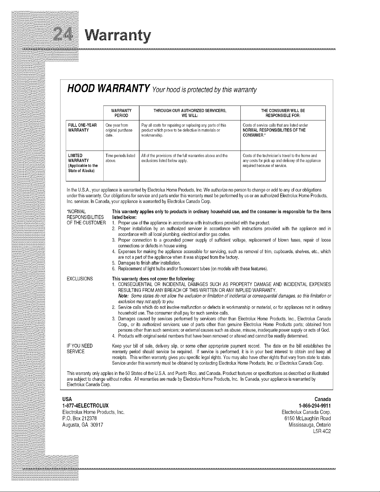
HOODWARRANTYYourhoodisprotected by this warranty
WARRANTY THROUGHOURAUTHORIZEDSERVICERS, THECONSUMERWILLBE
PERIOD WEWILL: RESPONSIBLEFOR:
FULLONE-YEAR Oneyearfrom Payallcostsforrepairingor replacinganypartsofthis Costsofservicecallsthatarelistedunder
WARRANTY originalpurchase productwhichproveto bedefectiveinmaterialsor NORMALRESPONSIBILITIESOFTHE
date. workmanship. CONSUMER.*
LIMITED Timeperiodslisted Alloftheprovisionsofthefullwarrantiesaboveandthe Costsofthetechnician'straveltothehomeand
WARRANTY above, exclusionslistedbelowapply, anycostsfor pickupanddelivelyoftheappliance
(Applicableto the requiredbecauseofservice.
Stateof Alaska)
In the U.S.A., yourapplianceis warrantedby ElectroluxHomeProducts,Inc.We authorizeno personto changeor add to anyd our obligations
underthis warranty.Our obligationsfor serviceand partsunderthis warrantymustbeperformedbyus oran authorizedElectroluxHomeProducts,
Inc.servicer.In Canada,your applianceis warrantedby ElectroluxCanadaCorp.
*NORMAL
RESPONSIBILITIES
OF THE CUSTOMER
This warranty applies onlyto products in ordinary householduse, and the consumer is responsible for the items
listed below:
1. Properuse of the appliancein accordancewith instructionsprovidedwiththe product.
2. Proper installation by an authorized servicer in accordance with instructions provided with the appliance and in
accordancewith alllocalplumbing,electricaland/orgas codes.
3. Proper connectionto a grounded power supply of sufficient voltage, replacementof blown fuses, repair of loose
connectionsor defectsin housewiring.
4. Expensesfor makingthe applianceaccessiblefor servicing,such as removalof trim, cupboards,shelves,etc., which
are not a part of the appliancewhen it wasshippedfromthe factory.
5. Damagesto finishafter installation.
6. Replacementof light bulbsand/orfluorescenttubes (on modelswiththese features).
EXCLUSIONS
This warrantydoesnot coverthefollowing:
1. CONSEQUENTIALOR INCIDENTALDAMAGES SUCH AS PROPERTYDAMAGEAND INCIDENTALEXPENSES
RESULTINGFROMANY BREACHOF THISWRITTENOR ANYIMPLIEDWARRANTY.
Note: Somestates do not allow the exclusionor limitationof incidentalor consequentialdamages,so this limitationor
exclusionmaynot applyto you.
2. Servicecalls whichdo not involvemalfunctionor defectsin workmanshipor material,or for appliancesnot in ordinary
householduse.The consumershall pay for such servicecalls.
3. Damagescaused by services performedby servicers other than ElectroluxHome Products,Inc., ElectroluxCanada
Corp., or its authorizedservicers; use of parts other than genuine Electrolux Home Products parts; obtainedfrom
personsotherthansuch servicers;orexternalcausessuch asabuse, misuse,inadequatepowersupplyor acts of God.
4. Pr_ductswith_rigina_seria_numbersthathavebeenrem_ved_ra_teredandcann_tbereadi_ydetermined_
IF YOUNEED
SERVICE
Keep your bill of sale, delivery slip, or some other appropriatepayment record. The date on the bill establishesthe
warranty period should service be required. If service is performed,it is in your best interest to obtain and keep all
receipts. Thiswrittenwarrantygivesyouspecificlegal rights.You may also have other rightsthat vary from state to state.
Serviceunderthis warrantymust beobtainedby contactingElectroluxHome Products,Inc.or ElectroluxCanadaCorp.
Thiswarrantyonly appliesin the50 Statesd the U.S.A.and PuertoRico,and Canada.Productfeaturesor specificationsasdescribedor illustrated
are subject to changewithoutnotice. All warrantiesare madeby ElectroluxHomeProducts,Inc. In Canada,your applianceiswarrantedby
ElectroluxCanadaCorp.
USA
1-877-4ELECTROLUX
Elect_lux HomeProducts,Inc.
P.O. Box212378
Augusta,GA 30917
Canada
1-866-294-9911
ElectroluxCanadaCorp.
6150McLaughlinRoad
Mississauga,Ontario
LSR4C2