
.
D-ILA
PROJECTOR
DLA-NZ9 DLA-RS4100
DLA-NZ8 DLA-RS3100
DLA-NZ7 DLA-RS2100
DLA-NP5 DLA-RS1100
.
.
http://manual3.jvckenwood.com/projector/mobile/global/
The Mobile User Guide can be viewed on mobile internet devices including
smartphones and tablets.
Mobile User Guide
.
For Customer use :
Enter below the serial No. which is located on the side of the cabinet. Retain this information for future reference.
Model No.
Serial No.
DLA-NZ9BK, DLA-NZ8BK, DLA-NZ7BK, DLA-NP5BK,
DLA-NZ9BE, DLA-NZ8BE, DLA-NZ7BE, DLA-NP5BE, DLA-NP5WE,
DLA-RS4100K, DLA-RS3100K, DLA-RS2100K, DLA-RS1100K,
DLA-RS4100E, DLA-RS3100E, DLA-RS2100E, DLA-RS1100E
Not suitable for household room illumination.
INSTRUCTIONS
B5A-3961-01
Getting Started Set up Operate Adjust/Set Maintenance
Troubleshooting
Others

Safety Precautions
Laser Source Model (DLA-NZ9, DLA-NZ8, DLA-NZ7, DLA-RS4100, DLA-RS3100, DLA-RS2100)
IMPORTANT INFORMATION
Supplier’s Declaration of Conformity
Trad e Na m e:
Products:
Model Name:
Responsible Party:
JVC
D-ILA Projector
DLA-NZ9BK, DLA-NZ8BK, DLA-NZ7BK,
DLA-RS4100K, DLA-RS3100K, DLA-RS2100K
JVCKENWOOD USA Corporation
1440 Corporate Drive, Irving, TX 75038
Telephone number: 678-449-8879
This device complies with Part 15 of the FCC Rules. Operation is subject to the
following two conditions;
(1) This device may not cause harmful interference, and
(2) This device must accept any interference received, including interference that
may cause undesired operation.
WARNING:
TO PREVENT FIRE OR SHOCK HAZARDS, DO
NOT EXPOSE THIS APPLIANCE TO RAIN OR
MOISTURE.
WARNING:
THIS APPARATUS MUST BE EARTHED.
CAUTION:
To reduce the risk of electric shock, do not remove
cover. Refer servicing to qualified service personnel.
This projector is equipped with a 3-blade grounding
type plug to satisfy FCC rule. If you are unable to
insert the plug into the outlet, contact your electrician.
NOISE EMISSION DECLARATION
The sound pressure level at the operator position is
equal or less than 60dB(A) according to ISO7779.
WARNING
REMOVE THE LENS COVER BEFORE TURNING
ON THE PROJECTOR
FCC INFORMATION (U.S.A. only)
CAUTION:
Changes or modification not approved by JVC could
void the user’s authority to operate the equipment.
Reorient or relocate the receiving antenna.
Increase the separation between the equipment
and receiver.
Consult the dealer or an experienced radio/TV
technician for help.
Connect the equipment into an outlet on a circuit
different from that to which the receiver is
connected.
NOTE:
This equipment has been tested and found to comply
with the limits for Class B digital devices, pursuant to
Part 15 of the FCC Rules. These limits are designed
to provide reasonable protection against harmful
interference in a residential installation. This
equipment generates, uses, and can radiate radio
frequency energy and, if not installed and used in
accordance with the instructions, may cause harmful
interference to radio communications. However,
there is no guarantee that interference will not occur
in a particular installation. If this equipment does
cause harmful interference to radio or television
reception, which can be determined by turning the
equipment off and on, the user is encourage to try to
correct the interference by one or more of the
following measures:
2
Getting Started
PORTABLE CART WARNING
(symbol provided by RETAC)
S3126A
-
-
-
-
-
-
-
-
-
-
-
-
-
IMPORTANT SAFEGUARDS
Electrical energy can perform many useful functions.
This unit has been engineered and manufactured to
assure your personal safety. But IMPROPER USE
CAN RESULT IN POTENTIAL ELECTRICAL
SHOCK OR FIRE HAZARD. In order not to defeat
the safeguards incorporated into this product,
observe the following basic rules for its installation,
use and service. Please read these Important
Safeguards carefully before use.
All the safety and operating instructions should be read
before the product is operated.
The safety and operating instructions should be retained for
future reference.
All warnings on the product and in the operating
instructions should be adhered to.
All operating instructions should be followed.
Place the projector near a wall outlet where the plug can be
easily unplugged.
Unplug this product from the wall outlet before cleaning.
Do not use liquid cleaners or aerosol cleaners. Use a damp
cloth for cleaning.
Do not use attachments not recommended by the product
manufacturer as they may be hazardous.
Do not use this product near water. Do not use immediately
after moving from a low temperature to high temperature,
as this causes condensation, which may result in fire,
electric shock, or other hazards.
Do not place this product on an unstable cart, stand, or
table. The product may fall, causing serious injury to a child
or adult, and serious damage to the product. The product
should be mounted according to the manufacturer’s
instructions, and should use a mount recommended by the
manufacturer.
When the product is used on a cart,
care should be taken to avoid quick
stops, excessive force, and uneven
surfaces which may cause the product
and cart to overturn, damaging
equipment or causing possible injury to
the operator.
Slots and openings in the cabinet are
provided for ventilation. These ensure reliable operation of
the product and protect it from overheating. These
openings must not be blocked or covered. (The openings
should never be blocked by placing the product on bed,
sofa, rug, or similar surface. It should not be placed in a
built-in installation such as a bookcase or rack unless
proper ventilation is provided and the manufacturer’s
instructions have been adhered to.)
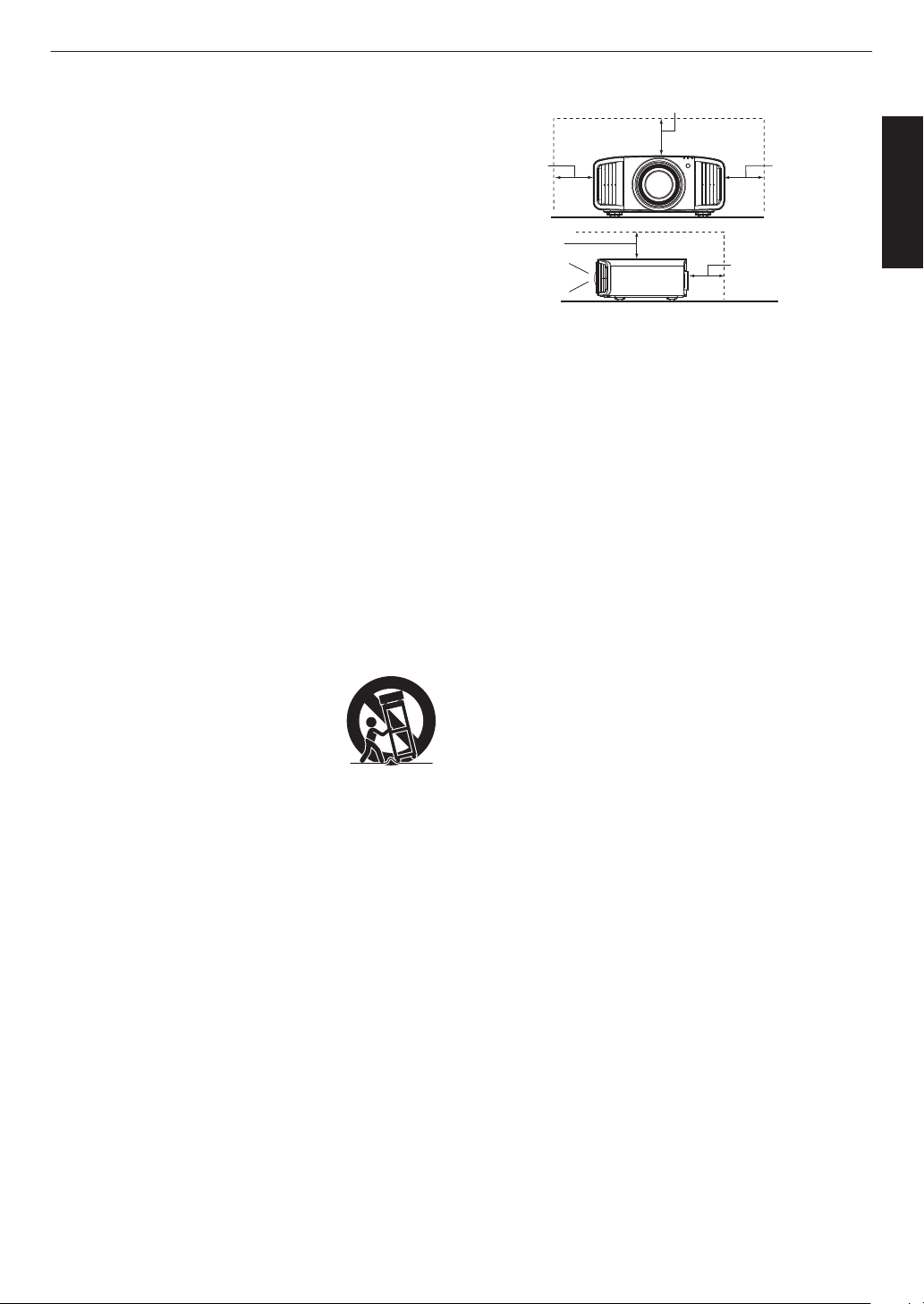
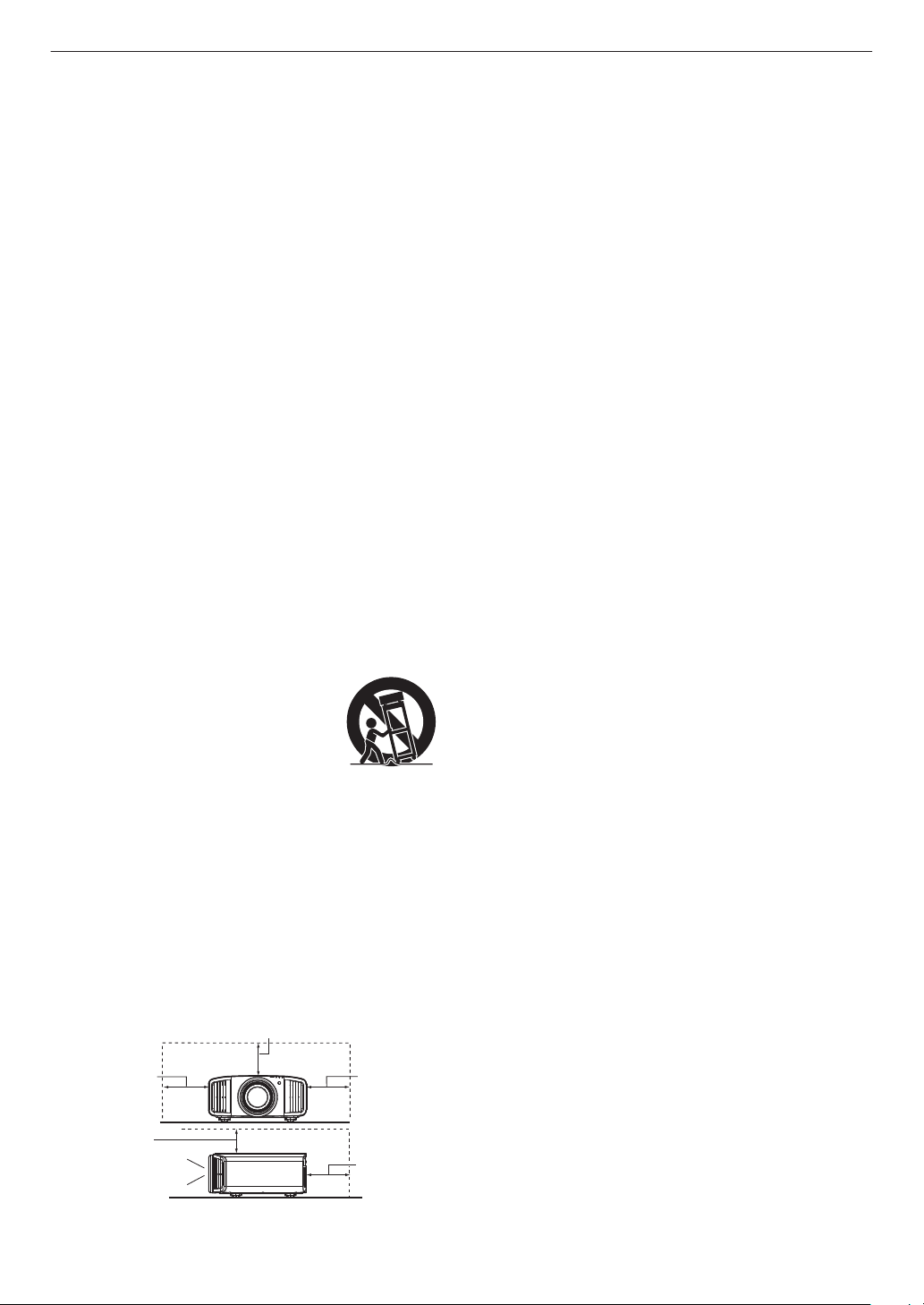
To allow better heat dissipation, keep a clearance between
this unit and its surrounding as shown below. When this unit
is enclosed in a space of dimensions as shown below, use
an air-conditioner so that the internal and external
temperatures are the same. Overheating can cause
damage.
-
-
-
-
-
-
-
-
a)
b)
c)
d)
e)
f)
When the power supply cord or plug is damaged.
If liquid has been spilled, or objects have fallen on the
product.
If the product has been exposed to rain or water.
If the product does not operate normally by following the
operating instructions. Adjust only those controls that
are covered by the Operation Manual, as an improper
adjustment of controls may result in damage and will
often require extensive work by a qualified technician to
restore the product to normal operation.
If the product has been dropped or damaged in any
way.
When the product exhibits a distinct change in
performance, this indicates a need for service.
Power source indicated on the label. If you are not sure of
the type of power supply to your home, consult your
product dealer or local power company.
This product is equipped with a three-wire plug. This plug
will fit only into a grounded power outlet. If you are unable
to insert the plug into the outlet, contact your electrician to
install the proper outlet. Do not defeat the safety purpose of
the grounded plug.
Power-supply cords should be routed so that they are not
likely to be walked on or pinched by items placed upon or
against them. Pay particular attention to cords at doors,
plugs, receptacles, and the point where they exit from the
product.
For added protection of this product during a lightning
storm, or when it is left unattended and unused for long
periods of time, unplug it from the wall outlet and
disconnect the cable system. This will prevent damage to
the product due to lightning and power line surges.
Do not overload wall outlets, extension cords, or
convenience receptacles on other equipment as this can
result in a risk of fire or electric shock.
Never push objects of any kind into this product through
openings as they may touch dangerous voltage points or
short out parts that could result in a fire or electric shock.
Never spill liquid of any kind on the product.
Do not attempt to service this product yourself as opening
or removing covers may expose you to dangerous voltages
and other hazards. Refer all service to qualified service
personnel.
Unplug this product from the wall outlet and refer service to
qualified service personnel under the following conditions:
Front
150 mm
(6 in) and
above
200 mm
(8 in) and
above
300 mm
(12 in) and
above
300 mm
(12 in) and
above
150 mm (6 in) and above
3
Getting Started

-
-
-
-
-
-
-
-
-
-
-
-
-
-
-
When replacement parts are required, be sure the service
technician has used replacement parts specified by the
manufacturer or with same characteristics as the original
part. Unauthorized substitutions may result in fire, electric
shock, or other hazards.
Upon completion of any service or repairs to this product,
ask the service technician to perform safety checks to
determine that the product is in proper operating condition.
The product should be placed more than one foot away
from heat sources such as radiators, heat registers, stoves,
and other products (including amplifiers) that produce heat.
When connecting other products such as VCR’s, and DVD
players, you should turn off the power of this product for
protection against electric shock.
Do not place combustibles behind the cooling fan. For
example, cloth, paper, matches, aerosol cans or gas
lighters that present special hazards when over heated.
Do not ceiling-mount the projector to a place which tends to
vibrate; otherwise, the attaching fixture of the projector
could be broken by the vibration, possibly causing it to fall
or overturn, which could lead to personal injury.
Use only the accessory cord designed for this product to
prevent shock.
For health reasons, please take a break of about 5-15
minutes every 30-60 minutes and let your eyes rest. When
using the devices with 3D function, please refrain from
watching any 3D-images when you feel tired, unwell or if
you feel any other discomfort. Moreover, in case you see a
double image, please adjust the equipment and software
for proper display. Please stop using the unit if the double
image is still visible after adjustment.
Once every three years, please perform an internal test.
This unit is provided with replacement parts needed to
maintain its function (such as cooling fans). Estimated
replacement time of parts can vary greatly depending on
frequency of use and the respective environment. For
replacement, please consult your dealer, or the nearest
authorized JVC service center.
When fixing the unit to the ceiling, Please note that we do
not take any responsibility, even during the warranty period,
if the product is damaged due to use of metal fixtures used
for fixation to the ceiling other than our own or if the
installation environment of said metal fixtures is not
appropriate. If the unit is suspended from the ceiling during
use, please be careful in regard to the ambient temperature
of the unit. If you use a central heating, the temperature
close to the ceiling will be higher than normally expected.
Video images can burn into the electronic component parts.
Please do not display screens with still images of high
brightness or high contrast, such as found in video games
and computer programs. Over a long period of time it might
stick to the picture element. There is no problem with the
playback of moving images, e.g. normal video footage.
Install the outlet at an accessible height to unplug from the
wall. Or install the circuit breaker at an accessible height to
shut down the projector. If you need information, please
consult your authorized dealer or specialist.
This unit is heavy in weight. Please ensure that there are at
least two persons carrying it.
Do not project images with the lens cover attached.
Otherwise, the lens cover may be deformed due to the
heat, or the projector may malfunction.
Do not place your hand into the opening near the lens while
lens shift is in progress. Otherwise, your hand may get
caught, resulting in an injury.
-
-
-
-
-
-
Not using the unit for a long time can lead to malfunction.
Please power it on and let it run occasionally. Please avoid
using the unit in a room where cigarettes are smoked. It is
impossible to clean optical component parts if they are
contaminated by nicotine or tar. This might lead to
performance degradation.
Please watch from a distance three times the height of the
projected image size. Persons with photosensitivity, any
kind of heart disease, or weak health should not use 3D
glasses.
Watching 3D-images might be cause of illness. If you feel
any change in your physical condition, please stop
watching immediately and consult a physician if necessary.
When watching 3D images, it is recommended to take
regular breaks. As the length and frequency of the required
breaks differ for every person, please judge according to
your own condition.
If your child watches while wearing 3D glasses, it should be
accompanied by its parents or an adult guardian. The adult
guardian should be careful to avoid situations where the
child’s eyes might become tired, as responses to tiredness
and discomfort, etc., are hard to detect, and it is possible
for the physical condition to deteriorate very quickly. As the
visual sense is not yet fully developed in children under the
age of 6, please consult a physician in regard to any
problem concerning 3D-images if necessary.
Note that when using the 3D feature, the video output may
appear different from the original video image due to image
conversion on the device.
* DO NOT allow any unqualified person to
install the unit.
Pay attention to the following when using the devices
with 3D function.
Be sure to ask your dealer to install the unit
(e.g.attaching it to the ceiling) since special
technical knowledge and skills are required for
installation. If installation is performed by an
unqualified person, it may cause personal injury or
electrical shock.
-
-
-
-
-
-
-
Do not use optical instruments (such as magnifying glass or
reflector) viewing the laser output. It may pose an eye
hazard.
When turning on the projector, ensure that no one is looking
into the projection lens.
Do not look into the lens and openings when the light is on.
Doing so would have serious effects on the human body.
Do not detach or attach the projection lens with the power
connected.
Attempting to disassemble, repair or modify the projector
yourself may lead to serious safety issues.
Using a faulty product not only results in electrical shock or
fire hazard, it can cause visual impairment.
When abnormality occur, stop using the projector
immediately and send it to your authorized dealer for repair.
About the installation place
Do not install the projector in a place that cannot
support its weight securely.
If the installation place is not sturdy enough, the
projector could fall or overturn, possibly causing
personal injury.
4
Getting Started
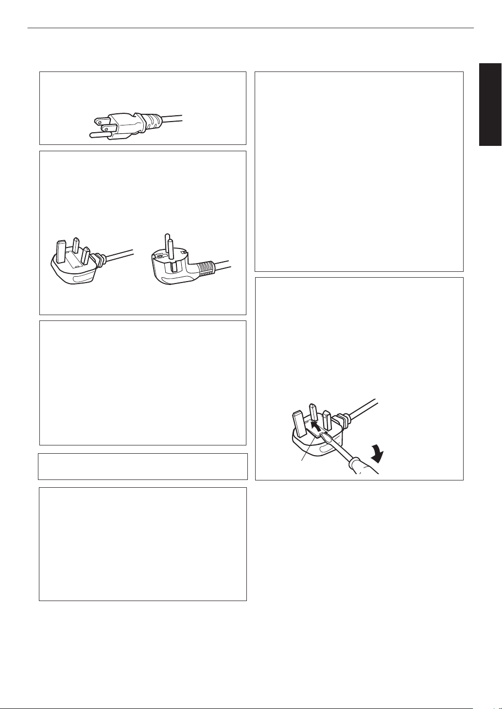
Power cord
Power cord
For European continent
countries
For United Kingdom
Green-and-yellow
Blue
Brown
Fuse
: Earth
: Neutral
: Live
POWER CONNECTION
WARNING:
WARNING:
Do not cut off the main plug from this
equipment.
The power supply voltage rating of this product is
AC100V – AC240V. Use only the power cord
designated by our dealer to ensure Safety and EMC.
Ensure that the power cable used for the projector is
the correct type for the AC outlet in your country.
Consult your product dealer.
If the plug fitted is not suitable for the power points
in your home or the cable is too short to reach a
power point, then obtain an appropriate safety
approved extension lead or adapter or consult your
dealer. If nonetheless the mains plug is cut off,
dispose of the plug immediately, to avoid a possible
shock hazard by inadvertent connection to the main
supply.
Dear Customer,
This apparatus is in conformance with the valid
European directives and standards regarding
electromagnetic compatibility and electrical safety.
European representative of
JVC KENWOOD Corporation is:
JVCKENWOOD Deutschland GmbH
Konrad-Adenauer-Allee 1-11,
61118 Bad Vilbel,
GERMANY
THIS APPARATUS MUST BE EARTHED.
IMPORTANT (Europe only):
The wires in the mains lead on this product are
colored in accordance with the following code:
HOW TO REPLACE THE FUSE:
POWER CONNECTION
(United Kingdom only)
When replacing the fuse, be sure to use only a
correctly rated approved type, re-fit the fuse cover.
IF IN DOUBT —— CONSULT A COMPETENT
ELECTRICIAN.
Open the fuse compartment with the blade
screwdriver, and replace the fuse.
(* An example is shown in the illustration below.)
As these colors may not correspond with the
colored making identifying the terminals in your
plug, proceed as follows:
The wire which is colored green-and-yellow must be
connected to the terminal which is marked M with
the letter E or the safety earth or colored green or
green-and-yellow. The wire which is colored blue
must be connected to the terminal which is marked
with the letter N or colored black.
The wire which is colored brown must be connected
to the terminal which is marked with the letter L or
colored red.
For USA and Canada only
Use only the following power cord.
5
Getting Started
ENGLISH
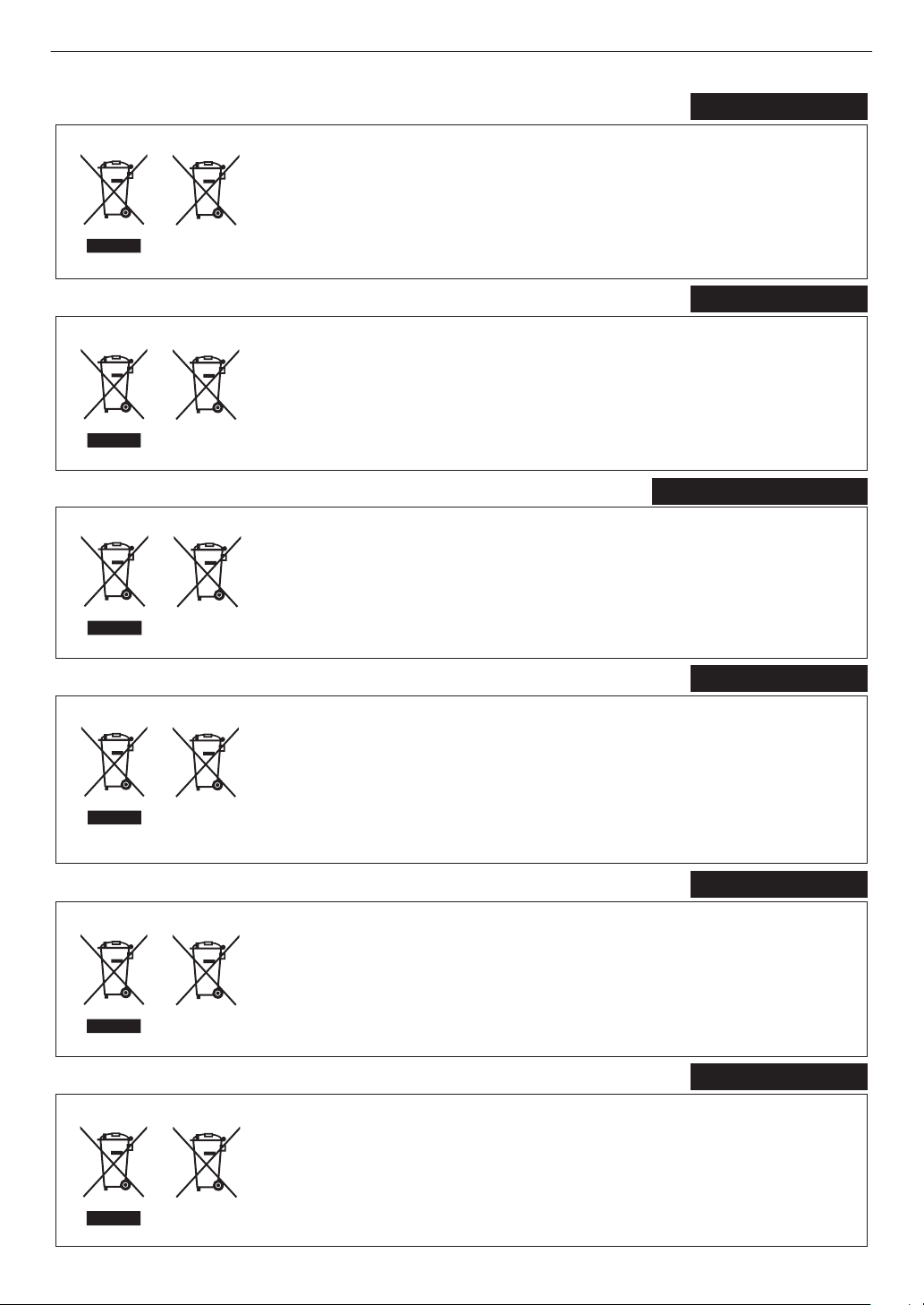
Information for Users on Disposal of Old Equipment and Batteries
[European Union only]
These symbols indicate that equipment with these symbols should not be disposed
of as general household waste. If you want to dispose of the product or battery,
please consider the collection systems or facilities for appropriate recycling.
Notice:
The sign Pb below the symbol for batteries indicates that this battery contains lead.
Benutzerinformationen zur Entsorgung alter Geräte und Batterien
[Nur Europäische Union]
Diese Symbole zeigen an, dass derartig gekennzeichnete Geräte nicht als normaler
Haushaltsabfall entsorgt werden dürfen. Wenden Sie sich zur Entsorgung des
Produkts oder der Batterie an die hierfür vorgesehenen Sammelstellen oder
Einrichtungen, damit eine fachgerechte Wiederverwertung möglich ist.
Hinweis:
Notification:
Das Zeichen Pb unterhalb des Batteriesymbols gibt an, dass diese
Batterie Blei enthält.
Informations relatives à l’élimination des appareils et des piles usagés, à l’intention des utilisateurs
[Union européenne seulement]
Si ces symboles figurent sur les produits, cela signifie qu’ils ne doivent pas être jetés
comme déchets ménagers. Si vous voulez jeter ce produit ou cette pile, veuillez
considérer le système de collecte des déchets ou les centres de recyclage appropriés.
La symbole Pb en dessous du symbole des piles indique que cette
pile contient du plomb.
Informatie voor gebruikers over het verwijderen van oude apparatuur en batterijen
[Alleen Europese Unie]
Deze symbolen geven aan dat apparatuur met dit symbool niet mag worden
weggegooid als algemeen huishoudelijk afval. Als u h
et product of de batterij wilt
weggooien, kunt u inzamelsystemen of faciliteiten voor een geschikte recycling
gebruiken.
Opmerking:
Het teken Pb onder het batterijsymbool geeft aan dat deze batterij lood bevat.
Battery
Products
Batterie
Produkte
Pile
Produits
Batterij
Producten
DEUTSCH
FRANÇAIS
NEDERLANDS
Información para los usuarios sobre la eliminación de baterías/pilas usadas
[Sólo Unión Europea]
Estos símbolos indican que el equipo con estos símbolos no debe desecharse
con la basura doméstica. Si desea desechar el producto o batería/pila, acuda
a los sistemas o centros de recogida para que los reciclen debidamente.
Atención: La indicación Pb debajo del símbolo de batería/pila indica que ésta
contiene plomo.
Baterías/pilas
Productos
ESPAÑOL / CASTELLANO
ITALIANO
Informazioni per gli utenti sullo smaltimento delle apparecchiature e batterie obsolete
[Solo per l’Unione Europea]
Questi simboli indicano che le apparecchiature a cui sono relativi non devono
essere smaltite tra i rifiuti domestici generici. Se si desidera smaltire questo
prodotto o questa batteria, prendere in considerazione i sistem i o le strutture di
raccolta appropriati per il riciclaggio corretto.
Nota:
Il simbolo Pb sotto il simbolo delle batter ie indica che questa batteria contiene piombo.
Batteria
Prodotti
6
Use of controls or adjustments or performance of procedures other than those specified herein may result in
hazardous laser radiation exposure.
L’utilisation de commandes ou de réglages ou l’exécution de procédures autres que celles décrites ici
pourrait provoquer une exposition à des radiations dangereuses.
El uso de controles o ajustes o la ejecución de procedimientos distintos a los especificados en este
documento puede resultar en la exposición peligrosa a la radiación láser.
Die Verwendung von Steuerungen oder Einstellungen oder die Durchführung von anderen als den hier
angegebenen Bedienverfahren kann dazu führen, dass Sie gefährlicher Laserstrahlung ausgesetzt werden.
L’uso di controlli, regolazioni o prestazioni di procedure diversi da quelli specificati in questo manuale
potrebbe causare una pericolosa esposizione alle radiazioni laser.
Использование элементов управления или регулировок или выполнение процедур, не указанных в
данном руководстве, может стать причиной опасного радиоактивного лазерного излучения.
Het gebruik van andere instellingen of aanpassingen of de uitvoering van andere procedures dan hierin
vermeld, kan leiden tot blootstelling aan gevaarlijke laserstraling.
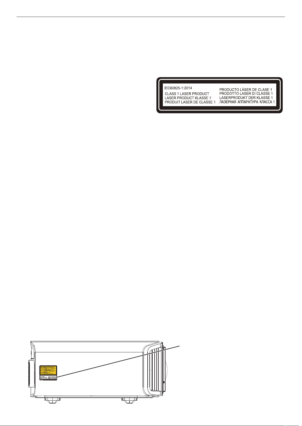
CLASS 1 LASER PRODUCT
PRODUIT LASER DE CLASSE 1
PRODUCTO LÁSER DE CLASE 1
LASERPRODUKT DER KLASSE 1
PRODOTTO LASER DI CLASSE 1
ЛАЗЕРНОЕ ИЗДЕЛИЕ КЛАССА 1
KLASSE 1 LASERPRODUCT
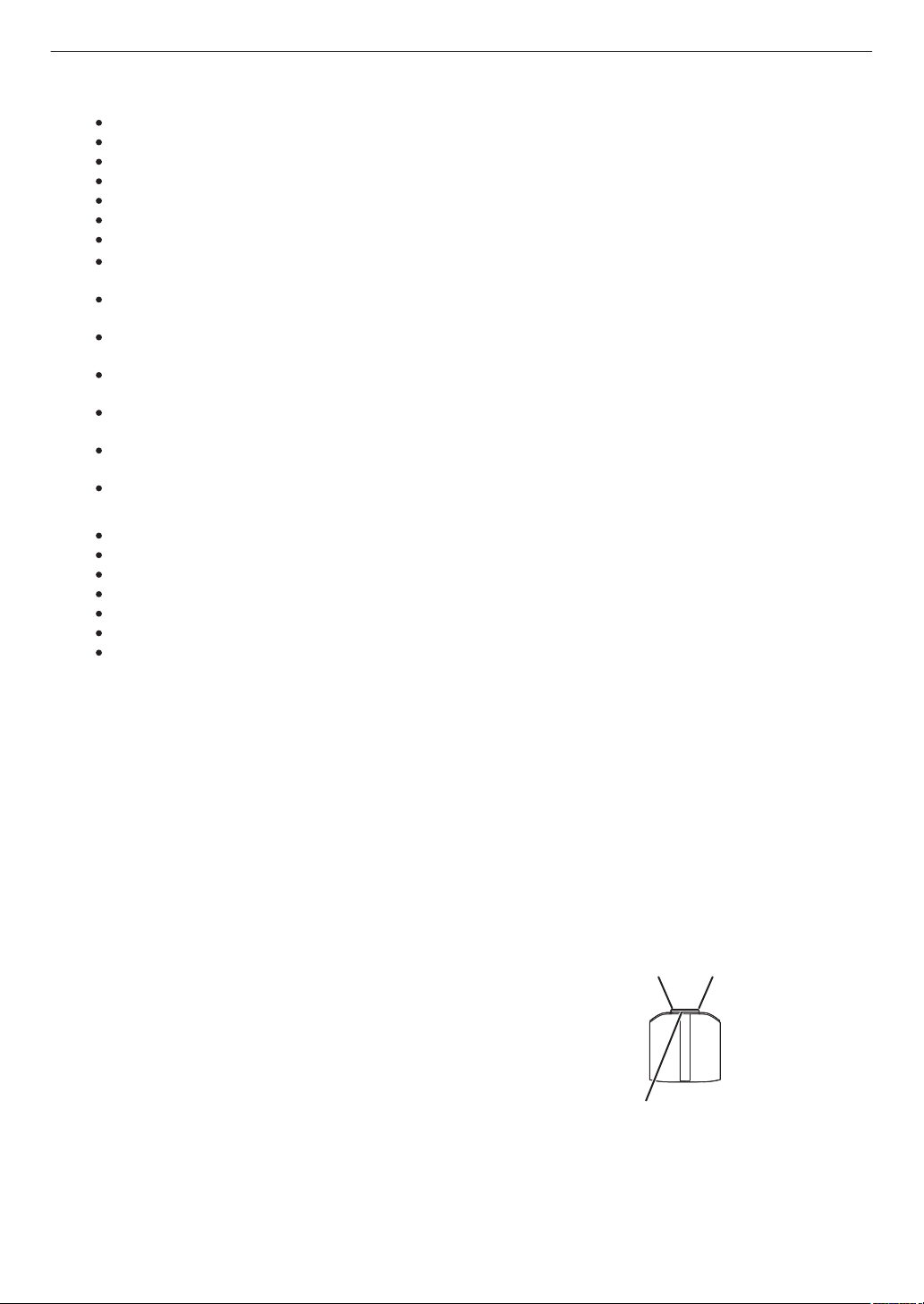
Location information of the labels
Informations d’emplacement des étiquettes
Información de la ubicación de las etiquetas
Informationen zur Lage der Etiketten
Informazioni sulla posizione delle etichette
Информация о расположении наклеек
Locatie-informatie van de etiketten
Do not look into the lens while in use.
Ne regardez pas dans l’objectif pendant son utilisation.
No mire directamente a la lente mientras está en uso.
Schauen Sie während der Verwendung nicht in die Linse.
Non guardare nell’obiettivo mentre è in uso.
Не смотрите в объектив, когда он используется.
Kijk niet in de lens terwijl deze in gebruik is.
WARNING/ATTENTION/ADVERTENCIA/WARNUNG/AVVERTENZA/ПРЕДУПРЕЖДЕНИЕ/
WAARSCHUWING
CAUTION/PRUDENCE/PRECAUCIÓN/ACHTUNG/ATTENZIONE/ВНИМАНИЕ/VOORZICHTIG
LASER CAUTION LABEL
ÉTIQUETTE DE MISE EN GARDE POUR LE LA
SER
ETIQUETA DE PRECAUCIÓN DEL LÁSER
LASERWARNSCHILD
ETICHETTA DI ATTENZIONE LASER
ЭТИКЕТКА С ПРЕДУПРЕЖДЕНИЕМ ОТНОСИТЕЛЬНО ЛАЗЕРА
LASER WAARSCHUWINGSETIKET
LASER CAUTION LABEL
ÉTIQUETTE DE MISE EN GARDE POUR LE
LASER
ETIQUETA DE PRECAUCIÓN DEL LÁSER
LASERWARNSCHILD
ETICHETTA DI ATTENZIONE LASER
ЭТИКЕТКА С ПРЕДУПРЕЖДЕНИЕМ
ОТНОСИТЕЛЬНО ЛАЗЕРА
LASER WAARSCHUWINGSETIKET
7
α
Light source specifications
Spécifications de la source de lumière
Especificaciones de la fuente de luz
Spezifikationen der Lichtquelle
Specifiche della sorgente luminosa
Характеристики источника света
Lichtbron specificaties
Beam divergence angle from lens of this unit
Angle de divergence du faisceau de l’objectif de cette unité
Ángulo de divergencia del haz desde la lente de esta unidad
Strahldivergenzwinkel der Linse dieses Geräts
Angolo di divergenza del fascio dall’obiettivo di questa unità
Угол расхождения луча от объектива данного устройства
Straaldivergentiehoek ten opzichte van de lens van dit toestel
Do not stare into the projector beam at any distance from the projector.
Ne regardez pas dans le faisceau du projecteur à n’importe quelle distance du projecteur.
No mire directamente al haz del proyector a ninguna distancia del mismo.
Blicken Sie nicht direkt in den Lichtstrahl vom Projektor, egal aus welcher Entfernung.
Non fissare il raggio del proiettore a qualsiasi distanza dal proiettore.
Не смотрите долго на луч проектора на любом расстоянии от проектора.
Kijk niet in de projectorstraal op enige afstand van de projector.
CAUTION/PRUDENCE/PRECAUCI
Ó
N/ACHTUNG/ATTENZIONE/ВНИМАНИЕ/VOORZICHTIG
Laser emission port
Port d’émission laser
Puerto de emisión láser
Laseraustrittsöffnung
Porta emissione laser
Порт лазерного излучения
Laseremissie-poort
Be careful to beam from lens when using the remote control for starting the projector while in front of the
projection lens.
Faites attention au faisceau de l’objectif lorsque vous utilisez la télécommande pour démarrer le
projecteur lorsque vous faites face à l’objectif de projection.
Tenga cuidado con el haz de la lente cuando utilice el mando a distancia para encender el proyector
mientras está frente a la lente de proyección.
Achten Sie auf die Projektorlinse, wenn Sie die Fernbedienung zum Starten des Projektors verwenden,
während Sie sich vor der Projektorlinse befinden.
Prestare attenzione al raggio proveniente dall’obiettivo quando si usa il telecomando per avviare il
proiettore mentre ci si trova davanti all’obiettivo di proiezione.
При использовании пульта дистанционного управления для запуска проектора перед объективом
проектора следует соблюдать осторожность относительно луча, исходящего из объектива.
Let op de straal van de lens wanneer u de afstandsbediening gebruikt om de projector te starten terwijl u
zich voor de projectielens bevindt.
Do not use of optical aids such as binoculars or telescopes inside the beam.
N’utilisez pas d’instruments optiques tels que des jumelles ou des télescopes à l’intérieur du faisceau.
No use ayudas ópticas como prismáticos o telescopios dentro del haz.
Verwenden Sie keine optischen Hilfsmittel wie Ferngläser oder Teleskope innerhalb des Lichtstrahls.
Non utilizzare dispositivi ottici come binocoli o telescopi all’interno del raggio.
Не используйте оптические вспомогательные устройства, такие как бинокль или телескопы внутри луча.
Gebruik geen optische hulpmiddelen zoals een verrekijker of telelens binnen de straal.
105W Laser diodes x 1, Wavelength 455nm, Maximum output is 105W
Diodes laser 105 W x 1, longueur d’onde 455 nm, sortie maximale 105 W
Diodos láser de 105 W x 1, longitud de onda de 455 nm, salida máxima de 105 W
105 W Laserdiode x 1, Wellenlänge 455 nm, maximale Ausgabeleistung 105 W
Diodi laser x 1 105 W, lunghezza d’onda 455 nm, l’uscita massima è 105 W
105 Вт, лазерные диоды x 1, длина волны 455 нм, максимальная выходная мощность 105 Вт
105 W laserdioden x 1, golflengte 455 nm, maximale uitvoer is 105 W
DLA-NZ9
α = 39°
(*1)
- 71°
(*2)
DLA-NZ8, DLA-N7
α = 33.5°
(*1)
- 62.7°
(*2)
*1:Tele/Télé/Tele/Tele/Teleobiettivo/Теле/Tele
*2:Wide/Large/Amplio/Weit/Grandangolo/Широкий/Breed
8
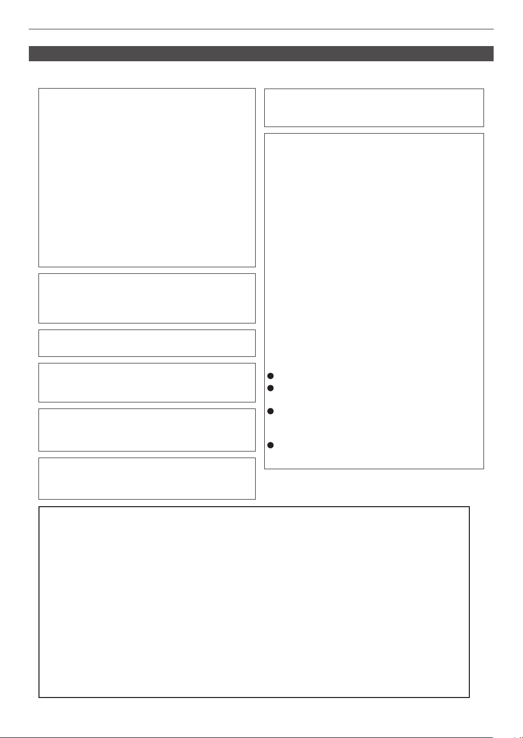
Location information of the labels
Informations d’emplacement des étiquettes
Información de la ubicación de las etiquetas
Informationen zur Lage der Etiketten
Informazioni sulla posizione delle etichette
Информация о расположении наклеек
Locatie-informatie van de etiketten
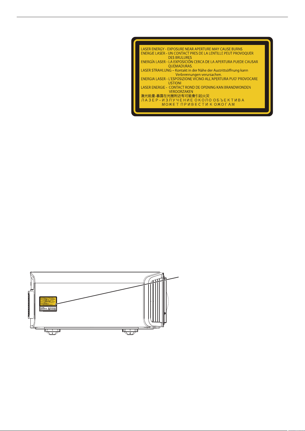
WARNING: LASER ENERGY - EXPOSURE NEAR APERTURE MAY CAUSE BURNS
AVERTISSEMENT : ÉNERGIE LASER - L’EXPOSITION À PROXIMITÉ DE L’OUVERTURE PEUT
ENTRAÎNER DES BRÛLURES
ADVERTENCIA: ENERGÍA LÁSER - LA EXPOSICIÓN CERCA DE LA APERTURA PUEDE CAUSAR
QUEMADURAS
WARNUNG: LASERENERGIE - EINE EXPOSITION NAHE DER AUSTRITTSÖFFNUNG KANN
VERBRENNUNGEN VERURSACHEN
AVVERTENZA: ENERGIA LASER - L’ESPOSIZIONE VICINO ALL’APERTURA PUÒ CAUSARE
USTIONI
ОСТОРОЖНО! ЛАЗЕРНАЯ ЭНЕРГИЯ - ИЗЛУЧЕНИЕ ВБЛИЗИ ДИАФРАГМЫ МОЖЕТ ВЫЗВАТЬ
ОЖОГИ
WAARSCHUWING: LASERENERGIE - BLOOTSTELLING NABIJ DIAFRAGMA KAN BRANDWONDEN
VEROORZAKEN
LASER ENERGY LABEL
ÉTIQUETTE D’ÉNER
GIE LASER
ETIQUETA ENERGÉTICA DEL LÁSER
LASERENERGIE-WARNSCHILD
ETICHETTA ENERGETICA LASER
ЭТИКЕТКА ОТНОСИТЕЛЬНО
ЛАЗЕРНОЙ ЭНЕРГИИ
LASERENERGIE-ETIKET
LASER ENERGY LABEL
ÉTIQUETTE D’ÉNERGIE LASER
ETIQUETA ENERGÉTICA DEL LÁSER
LASERENERGIE-WARNSCHILD
ETICHETTA ENERGETICA LASER
ЭТИКЕТКА ОТНОСИТЕЛЬНО
ЛАЗЕРНОЙ ЭНЕРГИИ
LASERENERGIE-ETIKET
9

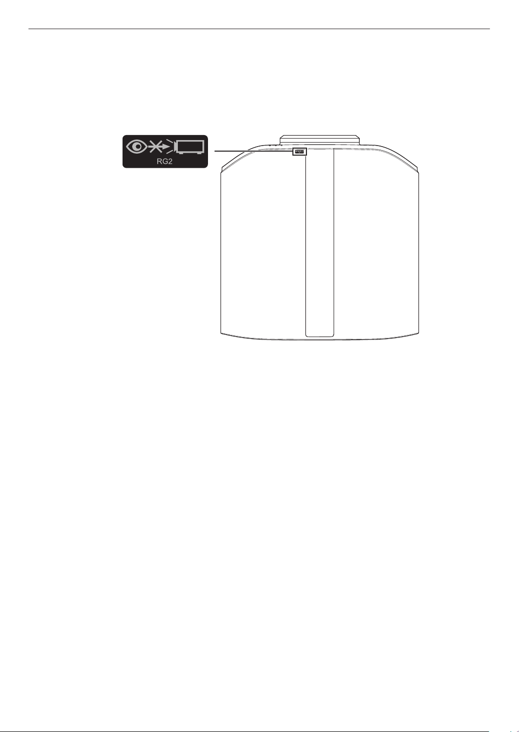
IEC62471-5
Location information of the mark / Informations d’emplacement du repère /
Información de la ubicación de la marca / Informationen zur Lage der Markierung /
Informazioni sulla posizione del marchio / Информация о расположении меток /
Locatie-informatie van de markering
As with any bright light source, do not stare into the beam, RG2 IEC 62471-5:2015
Tout comme pour n’importe quelle source lumineuse brillante, ne regardez pas fixement le faisceau, RG2
IEC 62471-5: 2015
Al igual que con cualquier fuente de luz brillante, no mire directamente al haz, RG2 IEC 62471-5:2015
Wie bei allen hellen Lichtquellen, schauen Sie nicht in den Strahl, RG2 IEC 62471-5:2015
Come con qualsiasi fonte di luce intensa, non fissare il raggio, RG2 IEC 62471-5:2015
Как и в случае с любым другим источником яркого света, не смотрите на луч, RG2 IEC 62471-5:2015
Net als bij andere felle lichtbron, kijk niet in de laserstraal, RG2 IEC 62471-5:2015
10
Lamp Source Model (DLA-NP5, DLA-RS1100)
This product has a High Intensity
Dis-charge (HID) lamp that contains
mercury. Manage in accord with
disposal laws.
Disposal of these materials may be
regulated in your community due to
environmental considerations. For
disposal or recycling information,
please contact your local authorities or
for USA, the Electronic Industries
Alliance: http://www.eiae.org. or call
1-800-252-5722(For USA)
or 1-800-964-2650(For Canada).
IMPORTANT INFORMATION
FCC INFORMATION (U.S.A. only)
CAUTION:
Changes or modification not approved by JVC could
void the user’s authority to operate the equipment.
Reorient or relocate the receiving antenna.
Increase the separation between the equipment
and receiver.
Consult the dealer or an experienced radio/TV
technician for help.
Connect the equipment into an outlet on a circuit
different from that to which the receiver is
connected.
NOTE:
This equipment has been tested and found to comply
with the limits for Class B digital devices, pursuant to
Part 15 of the FCC Rules. These limits are designed
to provide reasonable protection against harmful
interference in a residential installation. This
equipment generates, uses, and can radiate radio
frequency energy and, if not installed and used in
accordance with the instructions, may cause harmful
interference to radio communications. However,
there is no guarantee that interference will not occur
in a particular installation. If this equipment does
cause harmful interference to radio or television
reception, which can be determined by turning the
equipment off and on, the user is encourage to try to
correct the interference by one or more of the
following measures:
WARNING
REMOVE THE LENS COVER BEFORE TURNING
ON THE PROJECTOR
WARNING:
TO PREVENT FIRE OR SHOCK HAZARDS, DO
NOT EXPOSE THIS APPLIANCE TO RAIN OR
MOISTURE.
WARNING:
THIS APPARATUS MUST BE EARTHED.
CAUTION:
To reduce the risk of electric shock, do not remove
cover. Refer servicing to qualified service personnel.
This projector is equipped with a 3-blade grounding
type plug to satisfy FCC rule. If you are unable to
insert the plug into the outlet, contact your electrician.
NOISE EMISSION DECLARATION
The sound pressure level at the operator position is
equal or less than 60dB(A) according to ISO7779.
Supplier’s Declaration of Conformity
Trad e Na m e:
Products:
Model Name:
Responsible Party:
JVC
D-ILA Projector
DLA-NP5BK, DLA-RS1100K
JVCKENWOOD USA Corporation
1440 Corporate Drive, Irving, TX 75038
Telephone number: 678-449-8879
This device complies with Part 15 of the FCC Rules. Operation is subject to the
following two conditions;
(1) This device may not cause harmful interference, and
(2) This device must accept any interference received, including interference that
may cause undesired operation.
11
PORTABLE CART WARNING
(symbol provided by RETAC)
S3126A
-
-
-
-
-
-
-
-
-
-
-
-
-
IMPORTANT SAFEGUARDS
Electrical energy can perform many useful functions.
This unit has been engineered and manufactured to
assure your personal safety. But IMPROPER USE
CAN RESULT IN POTENTIAL ELECTRICAL
SHOCK OR FIRE HAZARD. In order not to defeat
the safeguards incorporated into this product,
observe the following basic rules for its installation,
use and service. Please read these Important
Safeguards carefully before use.
All the safety and operating instructions should be read
before the product is operated.
The safety and operating instructions should be retained for
future reference.
All warnings on the product and in the operating
instructions should be adhered to.
All operating instructions should be followed.
Place the projector near a wall outlet where the plug can be
easily unplugged.
Unplug this product from the wall outlet before cleaning.
Do not use liquid cleaners or aerosol cleaners. Use a damp
cloth for cleaning.
Do not use attachments not recommended by the product
manufacturer as they may be hazardous.
Do not use this product near water. Do not use immediately
after moving from a low temperature to high temperature,
as this causes condensation, which may result in fire,
electric shock, or other hazards.
Do not place this product on an unstable cart, stand, or
table. The product may fall, causing serious injury to a child
or adult, and serious damage to the product. The product
should be mounted according to the manufacturer’s
instructions, and should use a mount recommended by the
manufacturer.
When the product is used on a cart,
care should be taken to avoid quick
stops, excessive force, and uneven
surfaces which may cause the product
and cart to overturn, damaging
equipment or causing possible injury to
the operator.
Slots and openings in the cabinet are
provided for ventilation. These ensure reliable operation of
the product and protect it from overheating. These
openings must not be blocked or covered. (The openings
should never be blocked by placing the product on bed,
sofa, rug, or similar surface. It should not be placed in a
built-in installation such as a bookcase or rack unless
proper ventilation is provided and the manufacturer’s
instructions have been adhered to.)
To allow better heat dissipation, keep a clearance between
this unit and its surrounding as shown below. When this unit
is enclosed in a space of dimensions as shown below, use
an air-conditioner so that the internal and external
temperatures are the same. Overheating can cause
damage.
-
-
-
-
-
-
-
-
a)
b)
c)
d)
e)
f)
When the power supply cord or plug is damaged.
If liquid has been spilled, or objects have fallen on the
product.
If the product has been exposed to rain or water.
If the product does not operate normally by following the
operating instructions. Adjust only those controls that
are covered by the Operation Manual, as an improper
adjustment of controls may result in damage and will
often require extensive work by a qualified technician to
restore the product to normal operation.
If the product has been dropped or damaged in any
way.
When the product exhibits a distinct change in
performance, this indicates a need for service.
Power source indicated on the label. If you are not sure of
the type of power supply to your home, consult your
product dealer or local power company.
This product is equipped with a three-wire plug. This plug
will fit only into a grounded power outlet. If you are unable
to insert the plug into the outlet, contact your electrician to
install the proper outlet. Do not defeat the safety purpose of
the grounded plug.
Power-supply cords should be routed so that they are not
likely to be walked on or pinched by items placed upon or
against them. Pay particular attention to cords at doors,
plugs, receptacles, and the point where they exit from the
product.
For added protection of this product during a lightning
storm, or when it is left unattended and unused for long
periods of time, unplug it from the wall outlet and
disconnect the cable system. This will prevent damage to
the product due to lightning and power line surges.
Do not overload wall outlets, extension cords, or
convenience receptacles on other equipment as this can
result in a risk of fire or electric shock.
Never push objects of any kind into this product through
openings as they may touch dangerous voltage points or
short out parts that could result in a fire or electric shock.
Never spill liquid of any kind on the product.
Do not attempt to service this product yourself as opening
or removing covers may expose you to dangerous voltages
and other hazards. Refer all service to qualified service
personnel.
Unplug this product from the wall outlet and refer service to
qualified service personnel under the following conditions:
-
-
-
-
When replacement parts are required, be sure the service
technician has used replacement parts specified by the
manufacturer or with same characteristics as the original
part. Unauthorized substitutions may result in fire, electric
shock, or other hazards.
Upon completion of any service or repairs to this product,
ask the service technician to perform safety checks to
determine that the product is in proper operating condition.
The product should be placed more than one foot away
from heat sources such as radiators, heat registers, stoves,
and other products (including amplifiers) that produce heat.
When connecting other products such as VCR’s, and DVD
players, you should turn off the power of this product for
protection against electric shock.
150 mm (6 in) and above
150 mm
(6 in) and
above
300 mm
(12 in) and
above
200 mm
(8 in) and
above
300 mm
(12 in) and
above
Front
12

-
-
-
-
-
-
-
-
-
-
-
-
-
Do not place combustibles behind the cooling fan. For
example, cloth, paper, matches, aerosol cans or gas
lighters that present special hazards when over heated.
Do not look into the projection lens while the illumination
lamp is turned on. Exposure of your eyes to the strong light
can result in impaired eyesight.
Do not look into the inside of this unit through vents
(ventilation holes), etc. Do not look at the illumination lamp
directly by opening the cabinet while the illumination lamp is
turned on. The illumination lamp also contains ultraviolet
rays and the light is so powerful that your eyesight can be
impaired.
Do not drop, hit, or damage the light-source lamp (lamp
unit) in any way. It may cause the light-source lamp to
break and lead to injuries. Do not use a damaged light
source lamp. If the light-source lamp is broken, ask your
dealer to repair it. Fragments from a broken light-source
lamp may cause injuries.
The light-source lamp used in this projector is a high
pressure mercury lamp. Be careful when disposing of the
light-source lamp. If anything is unclear, please consult
your dealer.
Do not ceiling-mount the projector to a place which tends to
vibrate; otherwise, the attaching fixture of the projector
could be broken by the vibration, possibly causing it to fall
or overturn, which could lead to personal injury.
Use only the accessory cord designed for this product to
prevent shock.
For health reasons, please take a break of about 5-15
minutes every 30-60 minutes and let your eyes rest. Please
refrain from watching any 3D-images when you feel tired,
unwell or if you feel any other discomfort. Moreover, in case
you see a double image, please adjust the equipment and
software for proper display. Please stop using the unit if the
double image is still visible after adjustment.
Once every three years, please perform an internal test.
This unit is provided with replacement parts needed to
maintain its function (such as cooling fans). Estimated
replacement time of parts can vary greatly depending on
frequency of use and the respective environment. For
replacement, please consult your dealer, or the nearest
authorized JVC service center.
When fixing the unit to the ceiling, Please note that we do
not take any responsibility, even during the warranty period,
if the product is damaged due to use of metal fixtures used
for fixation to the ceiling other than our own or if the
installation environment of said metal fixtures is not
appropriate. If the unit is suspended from the ceiling during
use, please be careful in regard to the ambient temperature
of the unit. If you use a central heating, the temperature
close to the ceiling will be higher than normally expected.
Video images can burn into the electronic component parts.
Please do not display screens with still images of high
brightness or high contrast, such as found in video games
and computer programs. Over a long period of time it might
stick to the picture element. There is no problem with the
playback of moving images, e.g. normal video footage.
Not using the unit for a long time can lead to malfunction.
Please power it on and let it run occasionally. Please avoid
using the unit in a room where cigarettes are smoked. It is
impossible to clean optical component parts if they are
contaminated by nicotine or tar. This might lead to
performance degradation.
Install the outlet at an accessible height to unplug from the
wall. Or install the circuit breaker at an accessible height to
shut down the projector. If you need information, please
consult your authorized dealer or specialist.
-
-
-
-
-
-
-
-
This unit is heavy in weight. Please ensure that there are at
least two persons carrying it.
Do not project images with the lens cover attached.
Otherwise, the lens cover may be deformed due to the
heat, or the projector may malfunction.
Do not place your hand into the opening near the lens while
lens shift is in progress. Otherwise, your hand may get
caught, resulting in an injury.
Please watch from a distance three times the height of the
projected image size. Persons with photosensitivity, any
kind of heart disease, or weak health should not use 3D
glasses.
Watching 3D-images might be cause of illness. If you feel
any change in your physical condition, please stop
watching immediately and consult a physician if necessary.
When watching 3D images, it is recommended to take
regular breaks. As the length and frequency of the required
breaks differ for every person, please judge according to
your own condition.
If your child watches while wearing 3D glasses, it should be
accompanied by its parents or an adult guardian. The adult
guardian should be careful to avoid situations where the
child’s eyes might become tired, as responses to tiredness
and discomfort, etc., are hard to detect, and it is possible
for the physical condition to deteriorate very quickly. As the
visual sense is not yet fully developed in children under the
age of 6, please consult a physician in regard to any
problem concerning 3D-images if necessary.
Note that when using the 3D feature, the video output may
appear different from the original video image due to image
conversion on the device.
* DO NOT allow any unqualified person to
install the unit.
Be sure to ask your dealer to install the unit
(e.g.attaching it to the ceiling) since special
technical knowledge and skills are required for
installation. If installation is performed by an
unqualified person, it may cause personal injury or
electrical shock.
About the installation place
Do not install the projector in a place that cannot
support its weight securely.
If the installation place is not sturdy enough, the
projector could fall or overturn, possibly causing
personal injury.
-
-
-
-
-
-
-
Do not use optical instruments (such as magnifying glass or
reflector) viewing the laser output. It may pose an eye
hazard.
When turning on the projector, ensure that no one is looking
into the projection lens.
Do not look into the lens and openings when the light is on.
Doing so would have serious effects on the human body.
Do not detach or attach the projection lens with the power
connected.
Attempting to disassemble, repair or modify the projector
yourself may lead to serious safety issues.
Using a faulty product not only results in electrical shock or
fire hazard, it can cause visual impairment.
When abnormality occur, stop using the projector
immediately and send it to your authorized dealer for repair.
13

Power cord
Power cord
For European continent
countries
For United Kingdom
Green-and-yellow
Blue
Brown
Fuse
: Earth
: Neutral
: Live
POWER CONNECTION
WARNING:
WARNING:
Do not cut off the main plug from this
equipment.
The power supply voltage rating of this product is
AC100V – AC240V. Use only the power cord
designated by our dealer to ensure Safety and EMC.
Ensure that the power cable used for the projector is
the correct type for the AC outlet in your country.
Consult your product dealer.
If the plug fitted is not suitable for the power points
in your home or the cable is too short to reach a
power point, then obtain an appropriate safety
approved extension lead or adapter or consult your
dealer. If nonetheless the mains plug is cut off,
dispose of the plug immediately, to avoid a possible
shock hazard by inadvertent connection to the main
supply.
Dear Customer,
This apparatus is in conformance with the valid
European directives and standards regarding
electromagnetic compatibility and electrical safety.
European representative of
JVC KENWOOD Corporation is:
JVCKENWOOD Deutschland GmbH
Konrad-Adenauer-Allee 1-11,
61118 Bad Vilbel,
GERMANY
THIS APPARATUS MUST BE EARTHED.
IMPORTANT (Europe only):
The wires in the mains lead on this product are
colored in accordance with the following code:
HOW TO REPLACE THE FUSE:
POWER CONNECTION
(United Kingdom only)
When replacing the fuse, be sure to use only a
correctly rated approved type, re-fit the fuse cover.
IF IN DOUBT —— CONSULT A COMPETENT
ELECTRICIAN.
Open the fuse compartment with the blade
screwdriver, and replace the fuse.
(* An example is shown in the illustration below.)
As these colors may not correspond with the
colored making identifying the terminals in your
plug, proceed as follows:
The wire which is colored green-and-yellow must be
connected to the terminal which is marked M with
the letter E or the safety earth or colored green or
green-and-yellow. The wire which is colored blue
must be connected to the terminal which is marked
with the letter N or colored black.
The wire which is colored brown must be connected
to the terminal which is marked with the letter L or
colored red.
For USA and Canada only
Use only the following power cord.
14

ENGLISH
Information for Users on Disposal of Old Equipment and Batteries
[European Union only]
These symbols indicate that equipment with these symbols should not be disposed
of as general household waste. If you want to dispose of the product or battery,
please consider the collection systems or facilities for appropriate recycling.
Notice:
The sign Pb below the symbol for batteries indicates that this battery contains lead.
Benutzerinformationen zur Entsorgung alter Geräte und Batterien
[Nur Europäische Union]
Diese Symbole zeigen an, dass derartig gekennzeichnete Geräte nicht als normaler
Haushaltsabfall entsorgt werden dürfen. Wenden Sie sich zur Entsorgung des
Produkts oder der Batterie an die hierfür vorgesehenen Sammelstellen oder
Einrichtungen, damit eine fachgerechte Wiederverwertung möglich ist.
Hinweis:
Notification:
Das Zeichen Pb unterhalb des Batteriesymbols gibt an, dass diese
Batterie Blei enthält.
Informations relatives à l’élimination des appareils et des piles usagés, à l’intention des utilisateurs
[Union européenne seulement]
Si ces symboles figurent sur les produits, cela signifie qu’ils ne doivent pas être jetés
comme déchets ménagers. Si vous voulez jeter ce produit ou cette pile, veuillez
considérer le système de collecte des déchets ou les centres de recyclage appropriés.
La symbole Pb en dessous du symbole des piles indique que cette
pile contient du plomb.
Informatie voor gebruikers over het verwijderen van oude apparatuur en batterijen
[Alleen Europese Unie]
Deze symbolen geven aan dat apparatuur met dit symbool niet mag worden
weggegooid als algemeen huishoudelijk afval. Als u h
et product of de batterij wilt
weggooien, kunt u inzamelsystemen of faciliteiten voor een geschikte recycling
gebruiken.
Opmerking:
Het teken Pb onder het batterijsymbool geeft aan dat deze batterij lood bevat.
Battery
Products
Batterie
Produkte
Pile
Produits
Batterij
Producten
DEUTSCH
FRANÇAIS
NEDERLANDS
Información para los usuarios sobre la eliminación de baterías/pilas usadas
[Sólo Unión Europea]
Estos símbolos indican que el equipo con estos símbolos no debe desecharse
con la basura doméstica. Si desea desechar el producto o batería/pila, acuda
a los sistemas o centros de recogida para que los reciclen debidamente.
Atención: La indicación Pb debajo del símbolo de batería/pila indica que ésta
contiene plomo.
Baterías/pilas
Productos
ESPAÑOL / CASTELLANO
ITALIANO
Informazioni per gli utenti sullo smaltimento delle apparecchiature e batterie obsolete
[Solo per l’Unione Europea]
Questi simboli indicano che le apparecchiature a cui sono relativi non devono
essere smaltite tra i rifiuti domestici generici. Se si desidera smaltire questo
prodotto o questa batteria, prendere in considerazione i sistem i o le strutture di
raccolta appropriati per il riciclaggio corretto.
Nota:
Il simbolo Pb sotto il simbolo delle batter ie indica che questa batteria contiene piombo.
Batteria
Prodotti
15
IEC62471-5
Location information of the mark / Informations d’emplacement du repère /
Información de la ubicación de la marca / Informationen zur Lage der Markierung /
Informazioni sulla posizione del marchio / Информация о расположении меток /
Locatie-informatie van de markering
As with any bright light source, do not stare into the beam, RG2 IEC 62471-5:2015
Tout comme pour n’importe quelle source lumineuse brillante, ne regardez pas fixement le faisceau, RG2
IEC 62471-5: 2015
Al igual que con cualquier fuente de luz brillante, no mire directamente al haz, RG2 IEC 62471-5:2015
Wie bei allen hellen Lichtquellen, schauen Sie nicht in den Strahl, RG2 IEC 62471-5:2015
Come con qualsiasi fonte di luce intensa, non fissare il raggio, RG2 IEC 62471-5:2015
Как и в случае с любым другим источником яркого света, не смотрите на луч, RG2 IEC 62471-5:2015
Net als bij andere felle lichtbron, kijk niet in de laserstraal, RG2 IEC 62471-5:2015
16

Contents
Getting Started
Safety Precautions ..................................................
2
Accessories/Optional Accessories ........................ 19
Check the Accessories ...................................... 19
Optional Accessories ......................................... 19
Controls and Features ........................................... 20
Main Unit - Front ................................................ 20
Main Unit - Bottom ............................................. 20
Main Unit - Side ................................................. 21
Main Unit - Rear ................................................. 21
Main Unit - Input Terminals ................................ 23
Remote Control ................................................. 24
Loading Batteries into the Remote Control ........ 25
Effective Range of Remote Control Unit ............ 25
Menu ................................................................. 26
Set up
Installing the Projector ........................................... 27
Precautions during Installation ........................... 27
Precautions during Mounting ............................. 28
Adjusting the Position ........................................ 29
Connecting the Projector ....................................... 30
Connecting to the HDMI Input Terminal (Digital Input)
....... 30
Connecting to the LAN Terminal ........................ 31
Connecting to the RS-232C Terminal ................ 31
Connecting to the TRIGGER Terminal ............... 32
Connecting the Power Cord (Supplied Accessory)
...... 32
Operate
Viewing Videos ...................................................... 33
Adjusting the Projector Screen .............................. 35
Adjusting the Lens According to the Projection
Position .............................................................. 35
Adjusting the Screen Size (Aspect) ................... 36
Viewing 3D Movies ................................................ 37
Installing the 3D Synchro Emitter ....................... 37
Viewing 3D Movies ............................................ 38
Adjusting 3D Movies .......................................... 38
Adjust/Set
Selecting an Image Quality According to the Video Type
........ 39
Setting the Picture Mode
........................................... 39
Setting the Color Profile
............................................ 41
Adjusting to your Preferred Color (Color Management)
...... 44
Viewing HDR Content ........................................... 45
HDR Feature on This Unit .................................. 45
Viewing HDR10+ Content .................................. 47
Setting Frame Adapt HDR ................................. 47
Using the “Theater Optimizer” ............................ 48
Adjusting Tone Mapping Automatically (Per Movie
or Title) .............................................................. 50
Collaboration with Panasonic UHD BD Player DP-
UB9000 ............................................................. 53
Fine-tuning the Image Quality ............................... 54
Adjusting the Output Value of the Projected Image
(Gamma/Tone Mapping)
...................................
54
Fine-tuning of Gamma/Tone Mapping to Preferred
Settings ............................................................. 57
Reducing the Delay and After-image of Fast-moving
Images (Motion Control) .................................... 59
Adjustments and Settings in the Menu .................. 61
List of Menu Items ............................................. 61
Picture Adjust ........................................... 64
Input Signal ............................................... 74
Installation ................................................ 77
Display Setup ........................................... 85
Function .................................................... 86
Information ................................................ 90
Maintenance
Replacing the Lamp 4 8 .........................
91
Lamp Replacement Procedure ..........................
91
Resetting the Lamp Time 4 8 ............. 93
Maintaining the Cabinet and Remote Control ........ 94
Cleaning and Replacing the Filter ......................... 94
Troubleshooting
Troubleshooting .................................................... 97
When the Following Messages Appear... ............ 102
Others
External Control .................................................. 103
RS-232C Specifications ................................... 103
TCP/IP Connection .......................................... 103
Command Format ............................................ 104
Remote Control Code ...................................... 105
Communications Example ............................... 106
Specifications ...................................................... 107
Software License Agreement .............................. 120
Important Notice concerning the Software .......... 122
Index ................................................................... 123
17
Getting Started

Symbols used in this manual
x indicates a function that is supported by DLA-NZ9.
y indicates a function that is supported by DLA-NZ8.
z indicates a function that is supported by DLA-NZ7.
4 indicates a function that is supported by DLA-NP5.
5 indicates a function that is supported by DLA-RS4100.
6 indicates a function that is supported by DLA-RS3100.
7 indicates a function that is supported by DLA-RS2100.
8 indicates a function that is supported by DLA-RS1100.
Items not marked with any of the above symbols are supported by all models.
The illustrations of the projector unit used in this manual are those of DLA-NZ9. The appearance of the projector of
other models may differ slightly.
18
Getting Started
Accessories/Optional Accessories
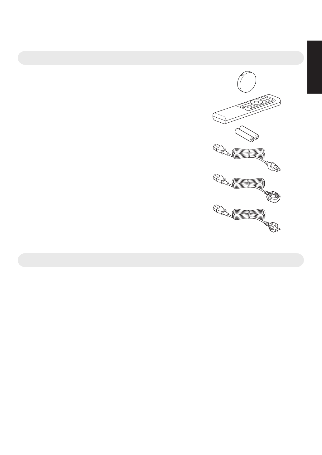
Check the Accessories
Lens cover .............................................................................. 1 piece
* It is attached to the main unit at the time of shipment.
Remote control ....................................................................... 1 piece
AAA-size batteries (for operational check) ............................ 2 pieces
Power cord (for USA) (about. 2 m (about. 78.7 in)) ................. 1 piece
Power cord (for UK) (about. 2 m (about. 78.7 in)) ................... 1 piece
Power cord (for EU) (about. 2 m (about. 78.7 in)) ................... 1 piece
0
Quick User Guide, safety precautions, warranty card, and other printed material are also included.
0
Be sure to read the “Safety Precautions” before using this projector.
Optional Accessories
0
Replacement lamp: Product no. PK-L2618U 4 8
0
3D Glasses: model PK-AG3
0
3D Synchro Emitter: model PK-EM2
19
Getting Started
Controls and Features
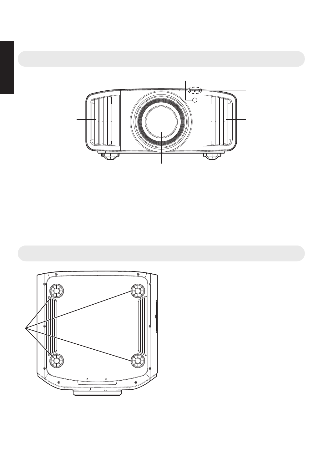
Main Unit - Front
A
B
C
D D
A
Lens
This is a projection lens. Do not look through the lens
while an image is projected.
B
Remote Sensor (front)
Please
aim
the remote control at this area when using
it.
* There is also a remote sensor at the rear.
C
Indicator
Refer to “Indicator Display on the Main Unit”P. 114.
D
Exhaust vent
Warm air is discharged to cool down the internal
temperature.
Do not block the vents.
Main Unit - Bottom
E
Feet
The
height
and angle of the projector can be adjusted by
turning the foot. (0 to 5 mm (0 to 0.2 in)) (P. 29)
When the foot is removed, it can be used as the mounting
hole for the ceiling mount bracket.
E
20
Getting Started
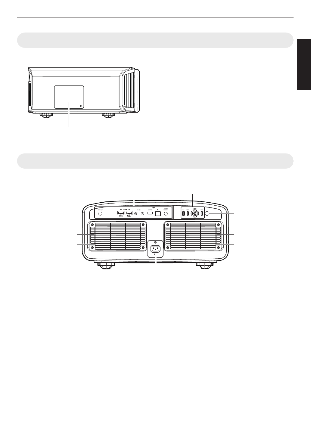
Main Unit - Side
4 8
F
Lamp Cover
When replacing the light source lamp, remove this cover.
(P. 91)
F
Main Unit - Rear
x y z 5 6 7
I
K
L
K
L
J
H
G
G
Input terminals
For details
on the terminals, refer to “Main Unit - Input
Terminals”P. 23.
H
Operation panel
For more details, please refer to the “Operation
panel”P. 22.
I
Remote Sensor (rear)
Please aim the remote control at this area when using
it.
* There is also a remote sensor at the front.
J
Power input terminal
Connect the supplied power cord to this terminal.
K
Air Inlets
The inlets take in air to cool down the internal
temperature.
Do
not block the inlet. Do not blow hot air on the inlet.
Doing so may cause the unit to malfunction.
L
Filter Cover
To perform maintenance of the filter, remove this
cover. (P. 94)
21
Getting Started
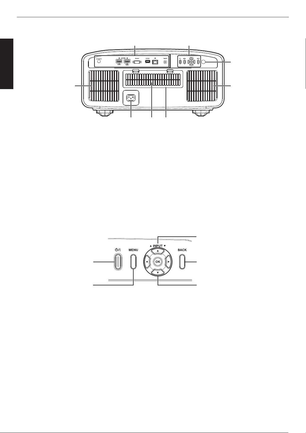
4 8
K LJ
I
K
K
G H
G
Input terminals
Please see “Main Unit - Input Terminals”P.
23 for
more details about the terminals.
H
Operation panel
For more details, please refer to the “Operation
panel” in the diagram below.
I
Remote Sensor (rear)
Please aim the remote control at this area when using
it.
* There is also a remote sensor at the front.
J
Power input terminal
Connect the supplied power cord to this terminal.
K
Air Inlets
The inlets take in air to cool down the internal
temperature.
Do
not block the inlet. Do not blow hot air on the inlet.
Doing so may cause the unit to malfunction.
L
Filter Cover
To perform maintenance of the filter, remove this
cover. (P. 94)
Operation panel
[MENU]: Displays the menu
[BACK]: Returns to the previous menu
[JKH I] keys: Selects an item
[OK]: Confirms a selection
[J INPUT K]: Switches the input
A: Turns “on”/“off” the
power
22
Getting Started
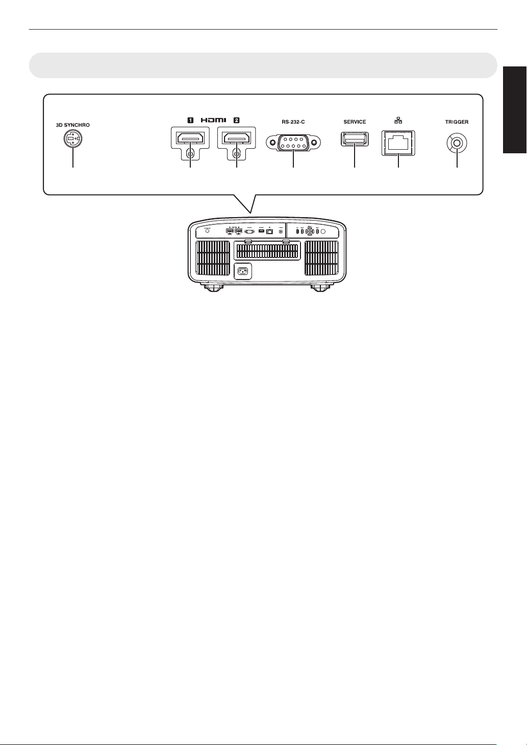
Main Unit - Input Terminals
A B C D E F G
A
[3D SYNCHRO] terminal
By connecting
a 3D Synchro Emitter (sold separately)
to this terminal, you can view 3D movies.
B
[HDMI 1] input terminal
C
[HDMI 2] input terminal
For connecting to devices that support HDMI output.
(P. 30)
D
[RS-232C] terminal (D-sub 9-pin
male)
The projector can be controlled by connecting a PC to
this terminal.
E
[SERVICE] terminal
For updating the software using a commercially
available USB flash drive.
F
[LAN] terminal (RJ-45)
The projector can be controlled by connecting it to a
PC through the computer network for control
commands to be sent to the projector.
G
[TRIGGER] terminal
Output
terminal for DC 12 V, 100 mA power supply. It
is used for sending output signals to control devices
such as an elevating screen that is equipped with a
trigger function.
Note that improper connection may damage the
projector. (Tip=DC +12 V, Sleeve=GND)
23
Getting Started
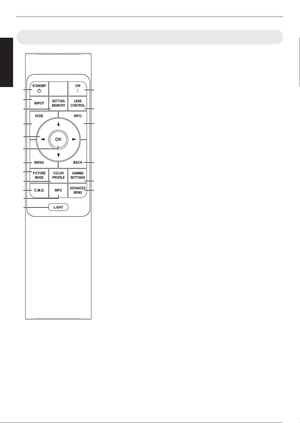
Remote Control
A
B [STANDBY]
Turns off the power. (P.
34)
B
C
[ON]
Turns on the power. (P. 33)
C
[INPUT]
Switches the input to [HDMI 1] or
[HDMI 2]. (P. 33)
D
[SETTING MEMORY]
Displays the installation mode
selection menu.
E
[LENS CONTROL]
For adjusting focus, zoom, and
shift. (P. 35)
0
Pressing the button each time
switches the setting in the
following sequence: “Focus” "
“Zoom” " “Shift”...
F
[HIDE]
Hides the image temporarily.
(P.
33)
G
[INFO.]
Displays the information menu.
(P. 90
)
H
[JKH I] keys
For selecting an item.
I
[OK]
Confirms a selected item.
J
[MENU]
Displays the menu, or hides the
menu if it is displayed.
K
[BACK]
Returns to the previous menu.
L
[PICTURE MODE]
Displays the picture mode
selection menu. (P. 39)
M
[COLOR PROFILE]
Displays
the color profile selection
menu. (P. 41)
N
[GAMMA SETTINGS]
Displays the gamma setting
menu.
O
[C.M.D.]
Displays the frame interpolation
selection menu. (P. 60)
P
[MPC]
Displays the MPC setting menu.
(P. 73)
Q
[ADVANCED MENU]
Pressing the button each time
toggles the menu display in the
following sequence: “Picture
Mode” " “Color Profile” " “Color
Temp.” " “Motion Control”.
R
[LIGHT]
Illuminates the buttons on the
remote control.
A
C
D
I
F
H
B
E
L
M
N
O
P
R
Q
G
J
K
24
Getting Started
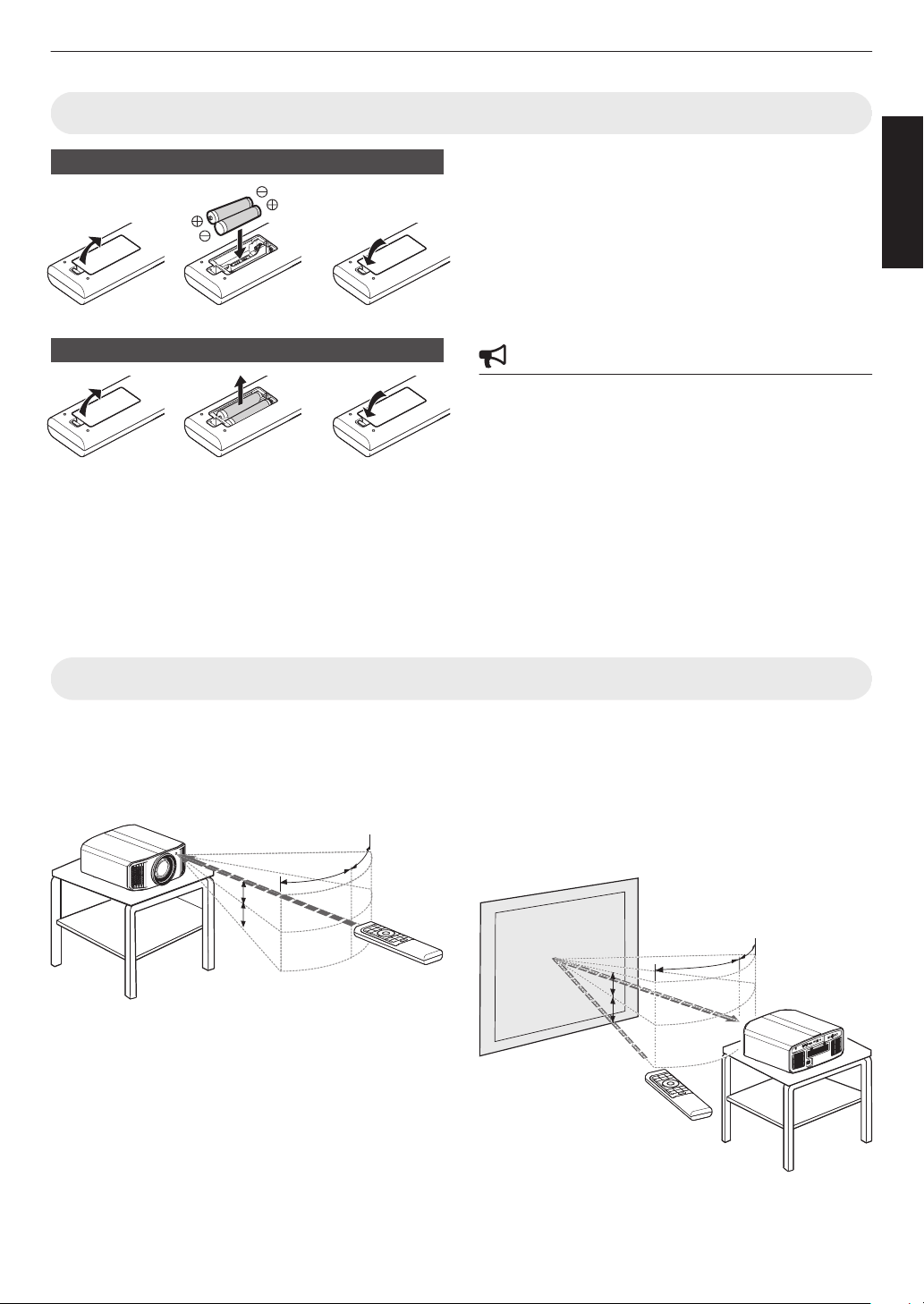
Loading Batteries into the Remote Control
Loading the batteries
Removing the batteries
0
If
the
remote control has to be brought closer to the unit
to operate, it means that the batteries are wearing out.
Replace the batteries with new ones (AAA).
0
Insert the batteries according to the t s marks.
Be sure to insert the s end first.
When removing the battery, do so from the t
end.
0
If an error occurs while using the remote control,
remove the batteries and wait for five minutes. Load
the batteries again and operate the remote control.
CAUTION
0
Do not put the remote control in a place with an
exposure
to
direct sun light or high temperature. It may
deformed due to heat, or the internal components may
be adversely affected resulting in fire hazard.
0
Remove the batteries from the remote control when
storing the
remote control. Storing the remote control
for a prolonged period without removing the batteries
can cause battery leakage.
0
Risk of
explosion if battery is replaced by an incorrect
type. Dispose of used batteries according to the
instructions.
0
If you want to dispose of the battery, please consider
the collection systems or facilities for appropriate
recycling.
Effective Range of Remote Control Unit
When aiming the remote control toward the sensor on this
unit (front
or rear), ensure that the distance to the sensor
is within 7 m (23 ft).
If the remote control fails to work properly, move closer
to this unit.
30°
30°
20°
20°
Remote Control
This unit
Control through reflection off a screen, etc.
Ensure that the total of distance A (between this unit and
the screen) and distance B (between the remote control
and the screen) is within 7 m (23 ft).
* As the efficiency of signals reflected from the remote
control unit varies with the type of screen used, the
operable distance may decrease.
A
B
30°
30°
20°
20°
20°
20°
20°
20°
Screen
Remote Control
This unit
25
Getting Started
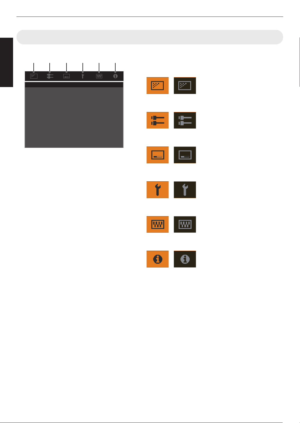
Menu
Select the icon at the top of the menu to display its corresponding
setting item as shown below.
A
Picture Adjust
B
Input Signal
C
Installation
D
Display Setup
E
Function
F
Information
A B C D E F
26
Getting Started
Installing the Projector
Precautions during Installation
Please read the following carefully before installing this
unit.
When carrying this unit
This unit is heavy in weight. Please ensure that there are
at least two persons carrying it. This unit weighs more
than 20 kg.
Do not install at the following
This unit is a precision device. Please refrain from
installing or
using it at the following locations. Otherwise,
it may cause fire or malfunction.
0
Dusty, wet and humid places
0
Places subject to oily smoke or cigarette smoke
0
On top of a carpet or bedding, or other soft surfaces
0
Places exposed to direct sunlight
0
Places with a high or low temperature
0
Do not install this unit in a room that is oily or subject
to
cigarette
smoke. Even a small quantity of smoke or
oiliness can have a long-term impact on this unit.
* This unit produces a great amount of heat, and is
designed to take in cool air to cool its optical
components. Using the unit at the above locations
may cause dirt to attach to the light path, thereby
resulting in dark images or dull colors.
* Dirt that sticks to the optical components cannot be
removed.
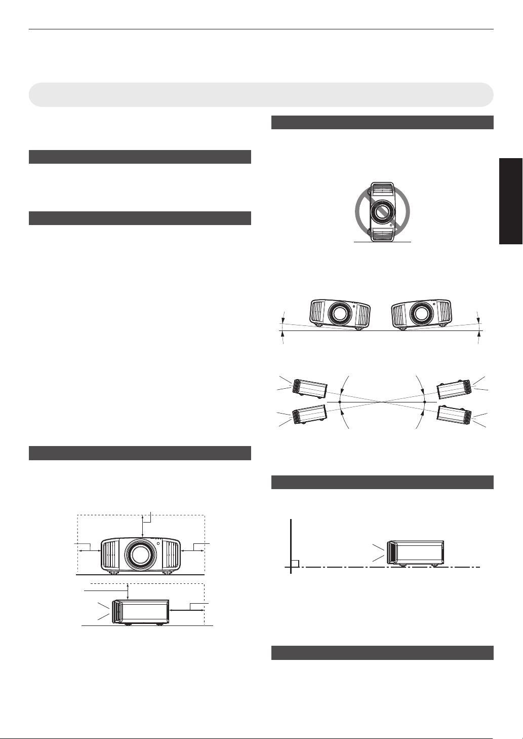
Maintain clearance from the wall, etc.
As the unit discharges a large amount of heat, install it
with adequate
clearance from the surroundings as shown
below.
Front
200 mm
(8 in) and
above
300 mm
(12 in) and
above
300 mm
(12 in) and
above
150 mm (6 in) and above
150 mm
(6 in) and
above
Leave the front area of the unit unblocked.
If there is any obstructing object in front of the exhaust
vent, hot
air will flow back to the unit and cause it to heat
up. Hot air flowing out of the unit may cast shadows on
the screen (heat haze phenomenon).
Using the unit
Please refrain from projecting in the following
circumstances. Otherwise, it may cause fire or
malfunction.
0
Projection with the unit stood vertically
0
Projection with the unit inclined at an angle
Angle to horizontal plane: within
±10
°x
y z 5 6 7; within
±5°4 8
10°/5° 10°/5°
Vertical inclination: within ± 10 °
10°
10°
10°
10°
0
Malfunction
may
occur if the angle is not set within the
above-mentioned range.
Installing the screen
Install the unit and the screen such that they are
perpendicular to each other.
Screen
Front
0
Please choose a screen material with non-uniform
patterns. Uniform patterns such as checks may cause
interference patterns to occur.
0
In this case, you can change the size of the screen to
make the interference patterns less noticeable.
Using the projector at a high altitude
When using this unit at a location that is higher than 900
m (3,000 ft) above sea level (low air pressure), set the
“High Altitude Mode” to “On”. (P. 89)
27
Set up
Precautions during Mounting
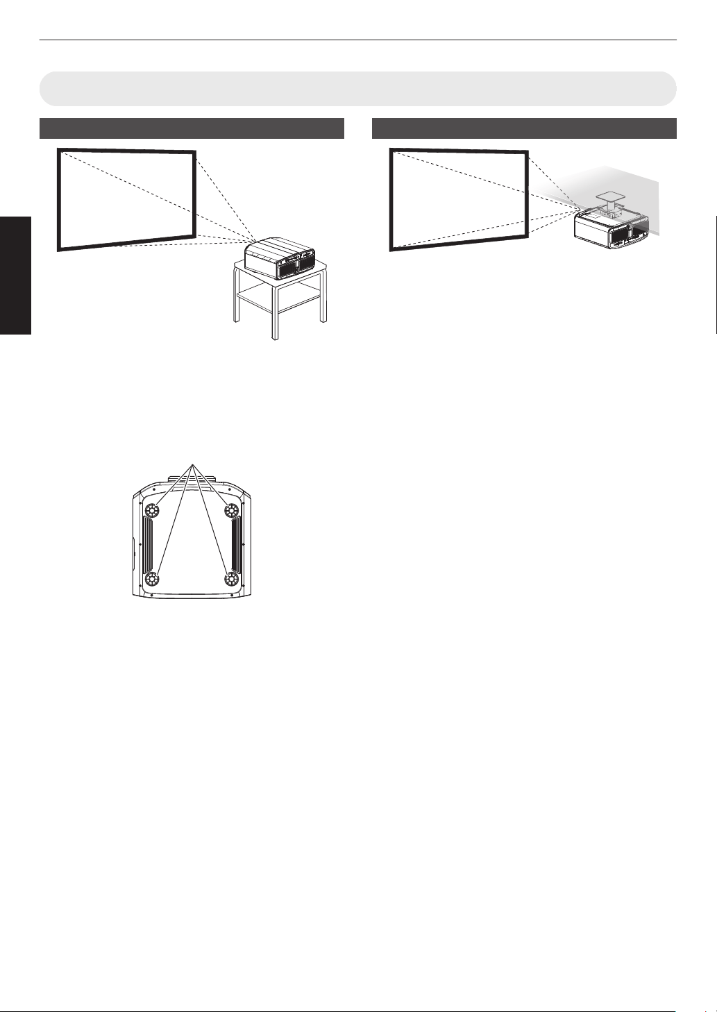
Securing (mounting) the projector
0
When this unit is to be mounted to a fixed position for
use, install it horizontally.
0
Make
sure
to secure the main unit to prevent accidents
such as during an earthquake.
Securing with screws
4 Locations
Remove the four feet at the bottom, and fasten using the
screws (M5 screws, 15 to 25 mm).
* Using screws other than ones mentioned may
damage the unit or cause the unit to fall from the
mount.
Securing the projector (ceiling mount)
0
Be sure to ask your dealer to install the unit for you.
Installing the unit on your own may cause the unit to
fall resulting in injury.
0
Take the necessary actions to prevent the main unit
from falling off such as during an earthquake.
0
Regardless
of
the warranty period, JVC is not liable for
any product damage caused by mounting the unit with
non-JVC ceiling fittings or to an environment that is not
suited for ceiling mount.
0
When using the unit with it suspended from a ceiling,
pay attention
to the surrounding temperature. When a
heater is in use, the temperature around the ceiling
may be higher than expected.
0
To attach
the unit to the ceiling mount bracket, set the
torque between the range of 1.5N m to 2.0N m.
Tightening with torque exceeding the above range
may cause damage to the unit, which may result the
unit to fall.
0
Use a projector mount that supports more than the
weight of the projector.
0
When reusing the ceiling mount bracket of an old
model, consult the specialist to check if there are any
issues with the surrounding space and increase in
weight.
0
Install
the outlet at an accessible height to unplug from
the wall. Or install the circuit breaker at an accessible
height to shut down the projector. If you need
information, please consult your authorized dealer or
specialist.
28
Set up
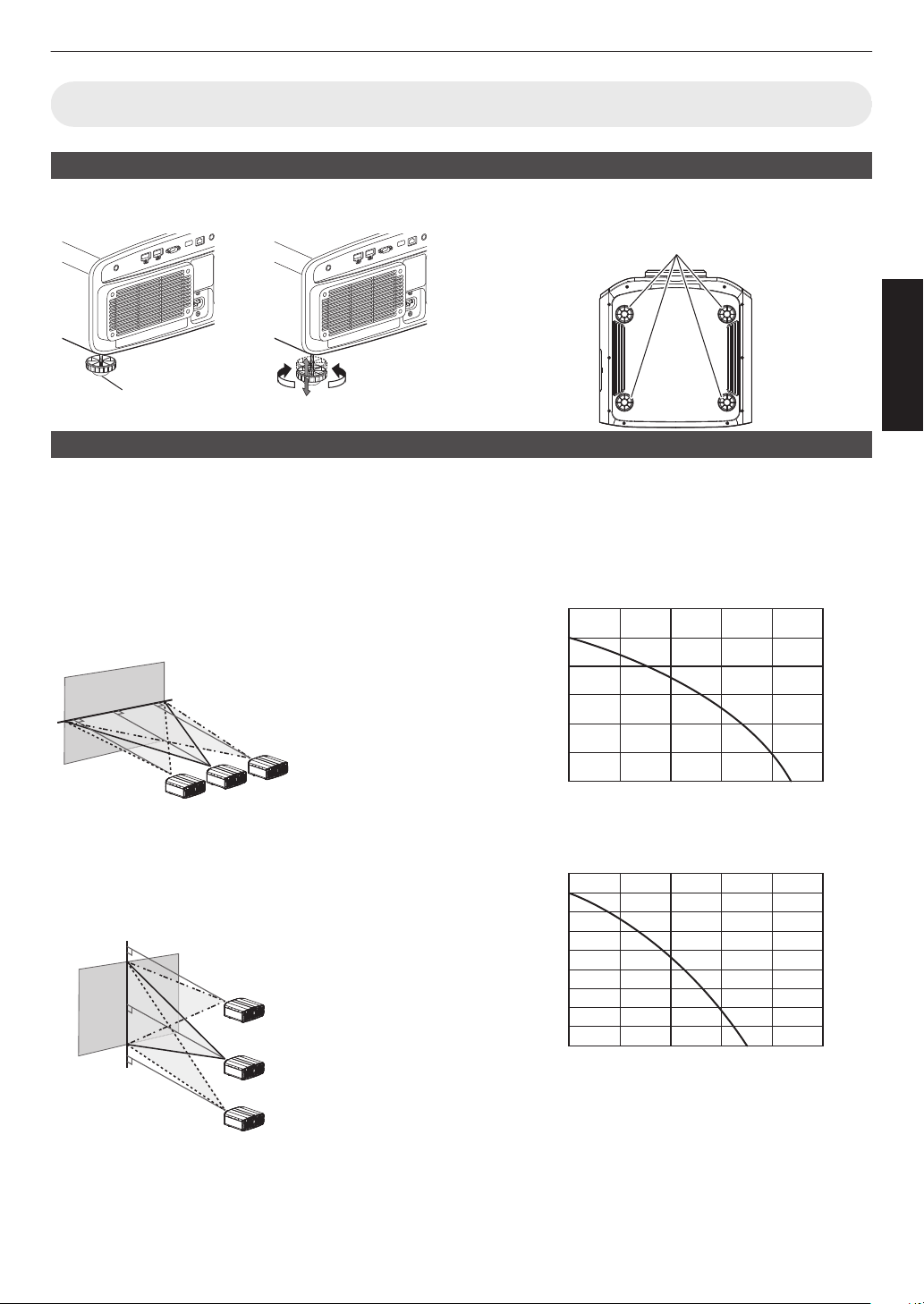
Adjusting the Position
Adjusting the elevation angle of the projector
The height and inclination of the unit (0 to 5 mm (0 to 0.2 in)) can be adjusted by turning the feet.
Lift the unit and adjust the four feet.
ContractExtend
Feet
4 Locations
Adjusting the position of the image
By using the lens shift feature of this unit, you can shift the image upward/downward or to the left/right. Set it to your
preferred position.
Æ “Adjusting the Lens According to the Projection Position” (P. 35)
Horizontal Position
Vertical Position: 0% (Center)
Up to about 43%
x 5 and 34%
y z 4 6 7 8 of the projected
image *
Vertical Position
Horizontal Position: 0 % (Center)
Up to about 100% x 5 and 80%
y z 4 6 7 8 of the projected
image *
* 16:9 image
Lens Shift Range (16:9)
x 5
120
100
80
60
40
20
0 10 3020 40 50
Amount of horizontal shift (%)
Amount of vertical shift (%)
y z 4 6 7 8
90
80
60
70
50
40
30
10
20
0 10 3020 40 50
Amount of horizontal shift (%)
Amount of vertical shift (%)
0
The maximum vertical shift varies with the amount of
horizontal shift.
Similarly, the maximum horizontal shift
also changes with the amount of vertical shift.
0
The values
on the graph are intended as a guide. Use
them for reference during installation.
29
Set up
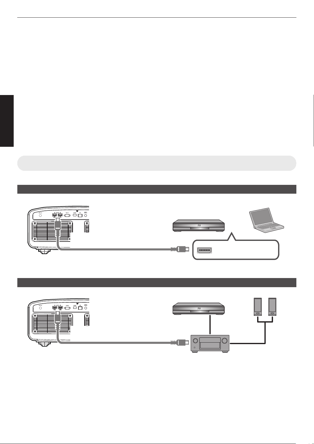
Connecting the Projector
0
Do not turn on the power until connection is complete.
0
The
connection
procedures differ according to the device used. For details, please refer to the instruction manual of
the device to be connected.
0
This projector is used for projecting images. To output the audio of connected devices, please connect a separate
audio output device, such as an amplifier or speaker.
0
Projector has no audio pass through or eARC output.
0
The images may not be displayed depending on the devices and cables to be connected. When using an HDMI
cable (sold separately), make use of one with the Ultra High Speed HDMI Cable certification (supports 48 Gbps).
0
Also, please refer to
“HDMI EDID Setting”P.
76.
0
Some cables cannot be connected to this unit due to the size of their connector cover.
0
Configuration of a network password is necessary before connecting to the LAN terminal. For details, refer to
“Network Password”P.
87.
(DLA-NZ9BK, DLA-NZ8BK, DLA-NZ7BK, DLA-NP5BK, DLA-RS4100K, DLA-RS3100K, DLA-RS2100K, DLA-
RS1100K)
Connecting to the HDMI Input Terminal (Digital Input)
Connecting via HDMI cable
HDMI Output Terminal
BD/DVD Recorder, etc.
Laptop, etc.
HDMI Cable (Sold Separately)
This Unit
To [HDMI 1] or [HDMI 2]
input terminal
0
If noise occurs, move the laptop away from this unit.
Connecting through an AV amplifier
HDMI Cable
(Sold Separately)
BD/DVD Recorder, etc.
HDMI Cable (Sold Separately)
This Unit
HDMI Cable (Sold Separately)
To [HDMI 1] or [HDMI 2]
input terminal
Speaker
Cable (Sold
Separately)
Speakers
AV Amplifier
0
If the
source device is connected to the projector through an intermediate device such as an AV amplifier or divider,
the video image may not appear depending on the specifications of the intermediate device.
In this case, connect the source device directly to the projector, and check whether the video image is displayed.
30
Set up
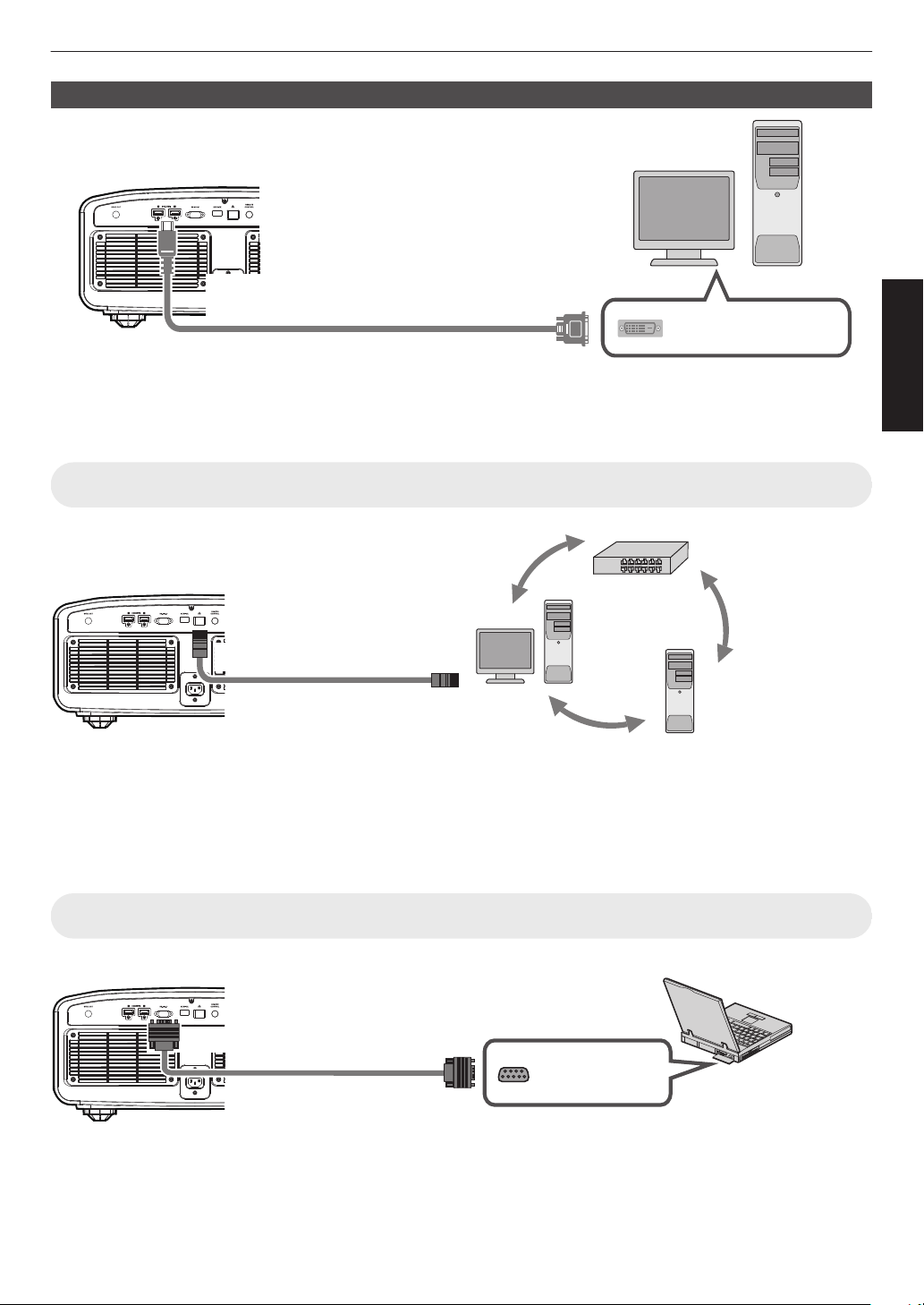
Connecting via HDMI-DVI conversion cable
HDMI-DVI Conversion Cable (Sold Separately)
To [HDMI 1] or [HDMI 2] input
terminal
This Unit
DVI Output Terminal
Desktop PC, etc.
0
If noise occurs, move the desktop PC away from this unit.
0
If the video is not displayed, try to reduce the length of the cable or lower the resolution of the video transmitting
equipment.
Connecting to the LAN Terminal
Desktop PC, etc.
Server
Hub
Network
Connection Cable
(Sold Separately)
This Unit
To [LAN] Terminal
0
The network is used to control this unit. It is not used for sending or receiving video signals.
0
Please contact your network administrator for information concerning the network connection.
0
Configuration of a network password is necessary before connecting to the LAN terminal. (
P.
87) (DLA-NZ9BK,
DLA-NZ8BK, DLA-NZ7BK, DLA-NP5BK, DLA-RS4100K, DLA-RS3100K, DLA-RS2100K, DLA-RS1100K)
0
Set “ECO Mode” to “Off” if LAN communication is performed in the Standby mode. (P. 86
)
0
For more information on control, please refer to “External Control”P. 103.
Connecting to the RS-232C Terminal
RS-232C Terminal
Laptop, etc.
RS-232C Connection
Cable (Sold Separately)
To [RS-232C] Terminal
This Unit
0
Set “ECO Mode” to “Off” if RS-232C communication is performed in the Standby mode. (P. 86
)
0
For more information on control, please refer to “External Control”P. 103.
31
Set up
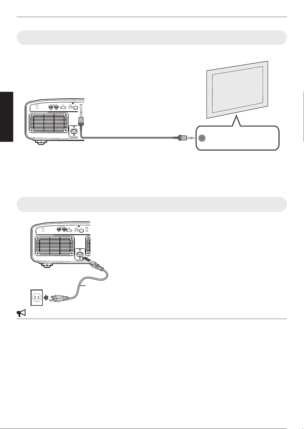
Connecting to the TRIGGER Terminal
Trigger Input Terminal (Ø3.5)
Screen
Trigger Cable (Sold Separately)
To [TRIGGER] Terminal
This Unit
0
Do not use it to supply power to other devices.
0
Connecting to the audio terminal of another device may cause the device to malfunction or break down.
0
Using beyond the rated value will cause the unit to malfunction.
0
The trigger terminal outputs a voltage of 12 V. Exercise adequate caution to prevent short circuit.
0
The factory setting is “Off”. To change the setting, configure the “Trigger” item in the menu (
P.
86).
Connecting the Power Cord (Supplied Accessory)
A
Connect
the
power cord supplied to the power input terminal on
the main unit
B
Insert the supplied power plug into the wall outlet.
Precautions to prevent fire and electric shock
0
The power consumption of this unit is large. Please connect it directly to the wall outlet supporting 15 A.
0
When you are not using the projector, please unplug the power cord from the outlet.
0
Connect it using only the power cord supplied.
0
Do not use a voltage other than the indicated power voltage.
0
Do not damage, break or modify the power cord. Do not place a heavy object on the power cord, or heat or pull it.
Doing so may damage the power cord.
0
Do not unplug the power cord with wet hands.
A
B
Power Cord
(Supplied)
32
Set up
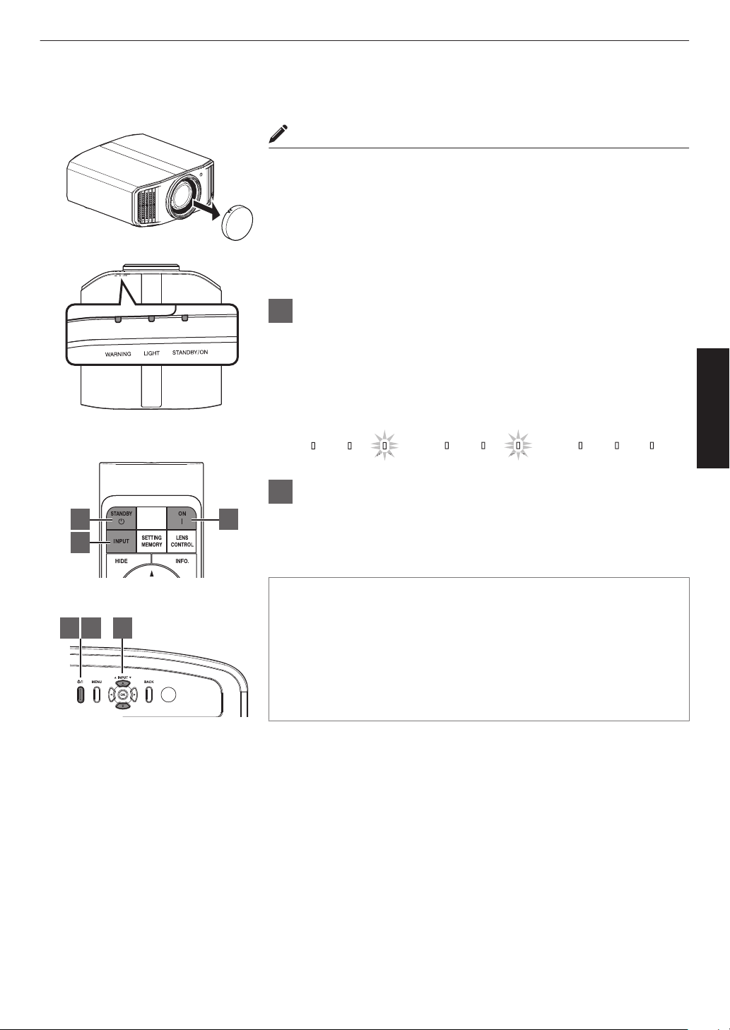
Viewing Videos
MEMO
0
Make sure to remove the lens cover.
0
Connect the power cord, and ensure that the “STANDBY/ON” indicator
lights up in red.
0
During standby in the “ECO Mode”, the “STANDBY/ON” indicator does
not light up even when the power cord is correctly connected.
In this case, cancel the standby mode by pressing any button on the
remote control unit, or use the A button on the projector unit when you
are turning on the power.
1
Turn on the power
Remote control: press the C [ON] button
Projector unit: press the A button
0
The “STANDBY/ON” indicator light switches from red (light off in
“ECO Mode”) to green (light goes off after the unit starts up).
LIGHTWARNING
STANDBY/ON
LIGHT
WARNING
STANDBY/ON
LIGHT
WARNING
STANDBY/ON
DB
AN
BY/O
DB
AN
BY/O
When in “ECO Mode”
“STANDBY/ON” light off
When light source is starting up
“STANDBY/ON” lights up (green)
In standby state
“STANDBY/ON” lights up (red)
2
Choose the image to project
Remote control/projector unit: press the [INPUT] button to switch the
input
0
Play back the selected device to project the image.
To hide the image temporarily
Press the [HIDE] button on the remote control
0
The “STANDBY/ON” indicator light starts to blink in green.
0
Press the [HIDE] button again to resume display of the image.
0
The power cannot be turned off when the image is temporarily hidden.
0
The
light
source is turned off when the “Hide Mode” is set to “On” in the
OSD menu. x y z 5 6 7
1
1 3 2
2
3
This unit
Remote Control
33
Operate
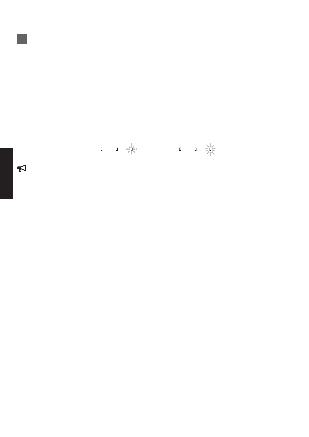
3
Turn off the power
Remote control: press the B [STANDBY] button
Projector unit: press the A button
0
While the “Are you sure you want to turn off?” message is displayed, press the button again.
0
The
light
of the LD block/lamp goes off, and the “STANDBY/ON” indicator switches from a green light to a red
blinking light.
0
After the light goes off, the fan will run for approximately 10 seconds x y z 5 6 7/
approximately 60
seconds 4 8 to cool down the LD block/lamp (Cool-down mode). Do not disconnect
the power cable while cooling is in progress.
0
Depending on the settings of the projector unit, cooling time may be about 30 seconds longer due to internal
processing.
0
After cooling is complete, the “STANDBY/ON” indicator switches from a blinking red to a solid red light.
LIGHTWARNING
STANDBY/ON
DB
TAN
Y/O
LIGHTWARNING
STANDBY/ON
DB
In standby state
“STANDBY/ON” lights up (red)
In the Cool-down mode
“STANDBY/ON” blinking (red)
CAUTION
0
The power cannot be turned off within approximately 80 seconds after it has been turned on. 4 8
0
The power cannot be turned on again while cooling is in progress.
0
Pull out the power plug when the unit is not to be used for a prolonged period of time.
0
If
the
indication of indicator differs from the description, refer to “Indicator Display on the Main Unit”P. 114 for details.
34
Operate
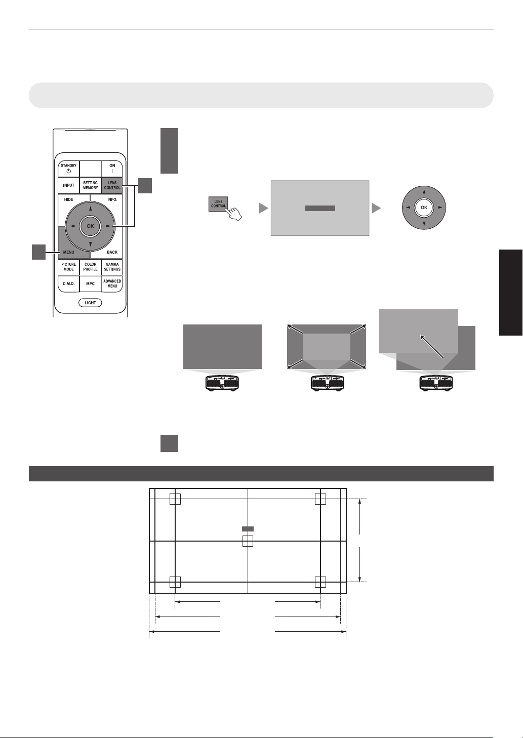
Adjusting the Projector Screen
Adjusting the Lens According to the Projection Position
1
Press the [LENS CONTROL] button, and use the [JKH I]
keys
to
adjust Focus, Zoom (screen size), and Shift (screen
position)
Focus
0
Pressing the
[LENS CONTROL] or [OK] button each time switches the mode
in the following sequence: “Focus” " “Zoom” " “Shift” " “Focus”...
0
Operation of the lens control feature is disabled when the lens lock is set to
“On”. (P.
78)
0
For more detailed information, please refer to “Lens Control”P. 78.
Shift (Screen Position)
Adjustment
Zoom (Screen Size)
Adjustment
ABCD
ABCD
ABCD
Focus Adjustment
2
Press the [MENU] or [BACK] button to end adjustment
Adjustment Pattern Displayed on the Adjustment Screen
2.35:1
1.33:1 (4:3)
Focus
1.78:1 (16:9)
1.89:1 (17:9)
Adjust the display according to the viewing angle of the respective aspect ratios for the adjustment patterns.
* This is not displayed when “Image Pattern” is configured to “Off”.
1
2
35
Operate
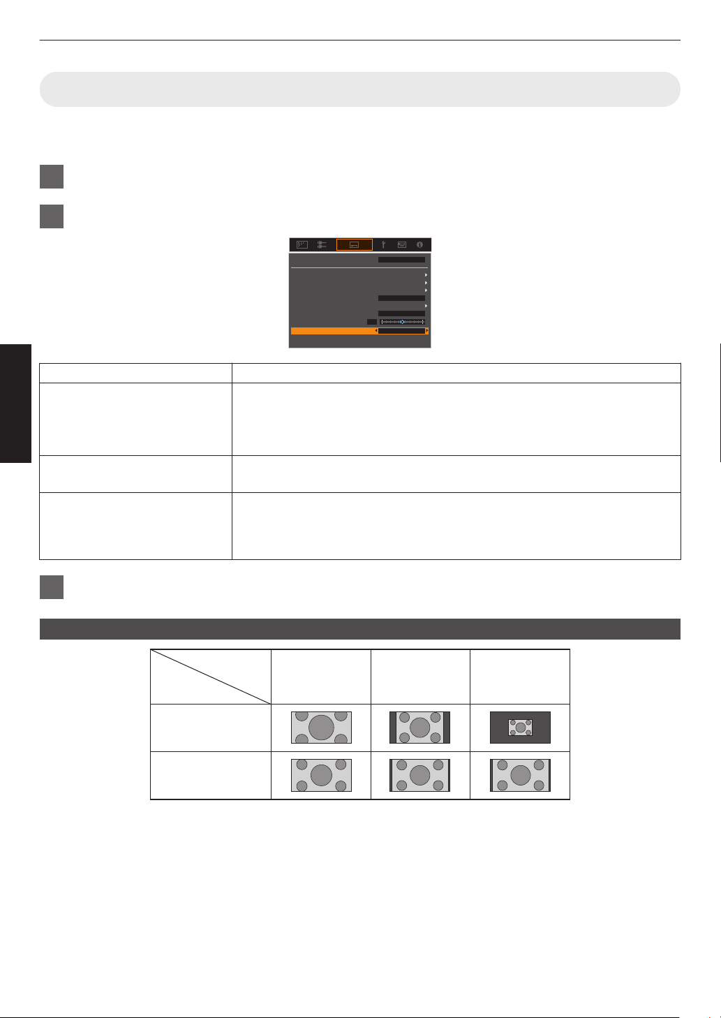
Adjusting the Screen Size (Aspect)
The screen size of the projected image can be adjusted optimally according to the original screen size (aspect) that
has been input.
1
Press the [MENU] button to display the menu
2
Select “Installation” " “Aspect” in the menu, then select the setting and press [OK]
0
Lens Control
Pixel Adjust
Mask
Screen Setting
Aspect
Anamorphic Off
Front
Auto
Installation Style
Mode 1
Keystone
Installation Mode
Setting Description
Zoom Magnifies the input image horizontally to the maximum while maintaining its aspect
ratio for display.
Part of the image that runs off the edge vertically will not be displayed.
* Displayed in a width of 3840 pixels when in the 3D mode.
Auto Magnifies the input image horizontally or vertically to the maximum while
maintaining its aspect ratio for display.
Native Any image below 1920x1080 and 2048x1080 will be scaled 4 times the native
resolution of the source.
Any source above 1920x1080 will be shown without any scaling. *2048x1080 the
exception.
3
Press the [MENU] button to exit
Example of input image and screen size
Zoom
720×480
1920×1080
Setting
Input Image
Size
Auto Native
36
Operate
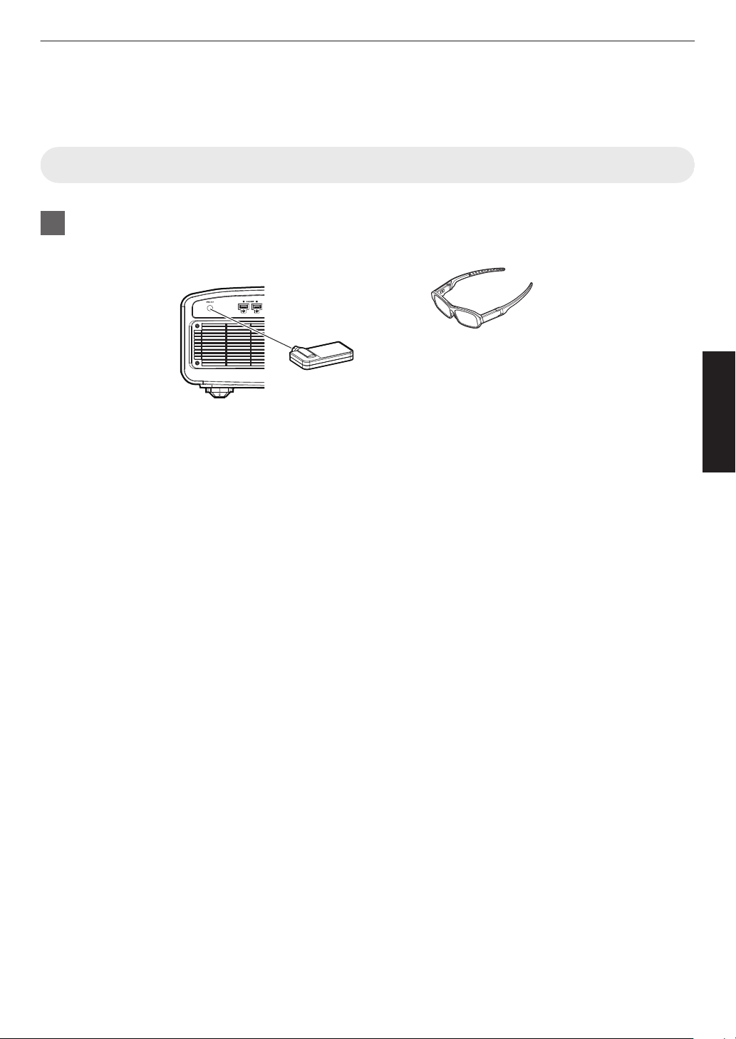
Viewing 3D Movies
By using the 3D Glasses (PK-AG3) and 3D Synchro Emitter (PK-EM2), both sold separately, you can enjoy 3D video
images.
Installing the 3D Synchro Emitter
1
Connect 3D Synchro Emitter to the [3D SYNCHRO] terminal on the main unit
Installation Example
3D Glasses
3D Synchro Emitter
PK-EM2
This Unit
PK-AG3
37
Operate
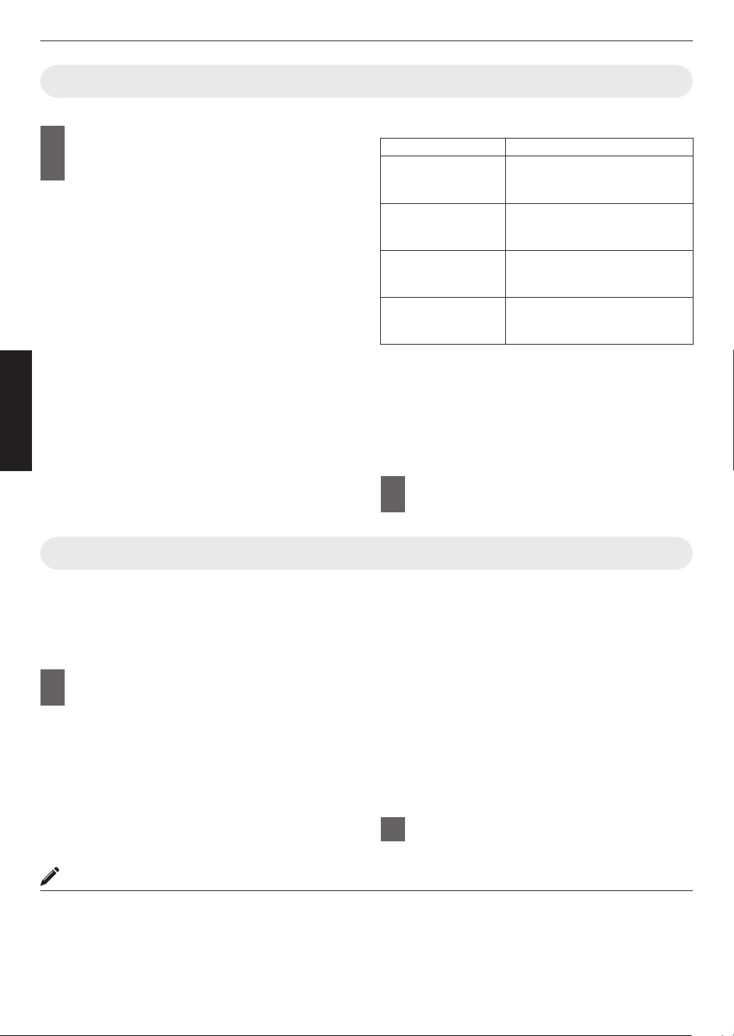
Viewing 3D Movies
1
Connect this unit to a 3D-compatible
HDMI device, and turn on the power
to play back the 3D video image
0
For
details
on how to play back 3D video images,
please refer to the instruction manual of the
player or recorder in use.
0
This unit supports the following 3D formats.
- Frame packing
- Side-by-side
- Top-and-bottom
Setting the 3D format
A
Select “Input Signal” " “3D
Setting” " “3D
Format”
in the menu
to switch the format
Format Description
Auto Automatically determines and
sets the
format upon receiving 3D
signal.
Side by Side Select this setting if the 3D input
signal is of the side-by-side
format.
Top and Bottom Select this setting if the 3D input
signal is of the top-and-bottom
format.
2D Select this setting if 2D images
are falsely recognized as 3D
ones.
* If a signal cannot be displayed as 3D image,
selecting the format does not switch the signal
to a 3D image.
For more information on possible input signals,
please refer to “Types of Possible Input
Signals”P.
113.
* In the default setting, “3D Format” is set to “Auto”
for automatic projection of 3D images.
2
Turn on the power of the 3D Glasses
and put them on
Adjusting 3D Movies
3D video images may appear differently to different
viewers. It may also be affected by your physical
condition at the time of viewing.
You are therefore recommended to adjust the video
images accordingly.
1
Select “Input Signal”"“3D Setting”
from the menu
Adjusting parallax (Parallax)
Adjust the displacement of the image for the left
and right eyes separately to obtain the best 3D
effect.
0
To do so, use the H I keys to move the cursor.
0
Setting range: -15 to +15
Adjusting crosstalk (Crosstalk Cancel)
Double images (overlapping of the left image with
the one on the right or vice versa) can be reduced
to deliver a clear quality.
0
To do so, use the H I keys to move the cursor.
0
Setting range: -8 to +8
2
Press the [MENU] button to exit
MEMO
0
The “3D Setting” settings are saved separately for each input terminal. The name of the currently selected input
terminal is shown at the top right corner of the “3D Setting” menu.
0
To
switch
to configure the settings for a different input terminal, press the [INPUT] button on the remote control unit,
or press the ↑↓ key on the projector unit after turning off the menu screen.
38
Operate
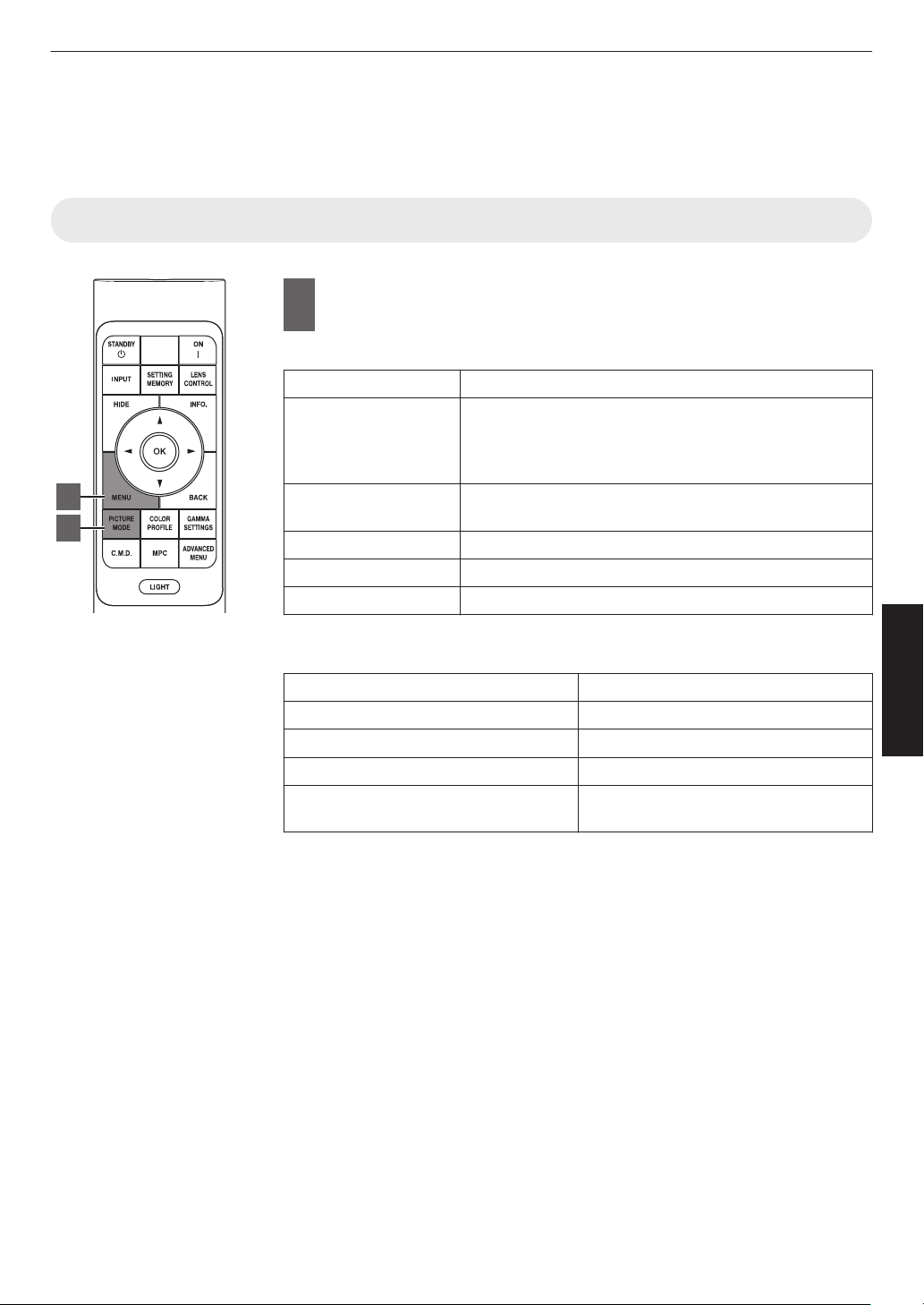
Selecting an Image Quality According to the
Video Type
Setting the Picture Mode
1
Press the [MENU] button to display the menu, followed by
using the
↑↓ keys to select “Content Type”. Next, press [OK]
Doing so enables selection of a picture mode that suits the content for viewing.
Item Description
Auto Switches the video type automatically according to the
input video system.
After switching
automatically, the picture mode switches to
the setting preconfigured in “Auto Pic.Mode Select”.
SDR Picture mode suitable for viewing SDR content. SDR
content includes 2D and 3D content.
HDR10+ Picture mode suitable for viewing HDR10+ content.
HDR10 Picture mode suitable for viewing HDR10 content.
HLG Picture mode suitable for viewing HLG content.
Configuring the video type to “Auto” automatically switches Content Type
according to the input video system.
HDMI Packet Information Content Type
HDR10+ HDR10+
ST2084 HDR10
HLG HLG
Other than the above/Out of Range/No
Signal
SDR
2
1
39
Adjust/Set
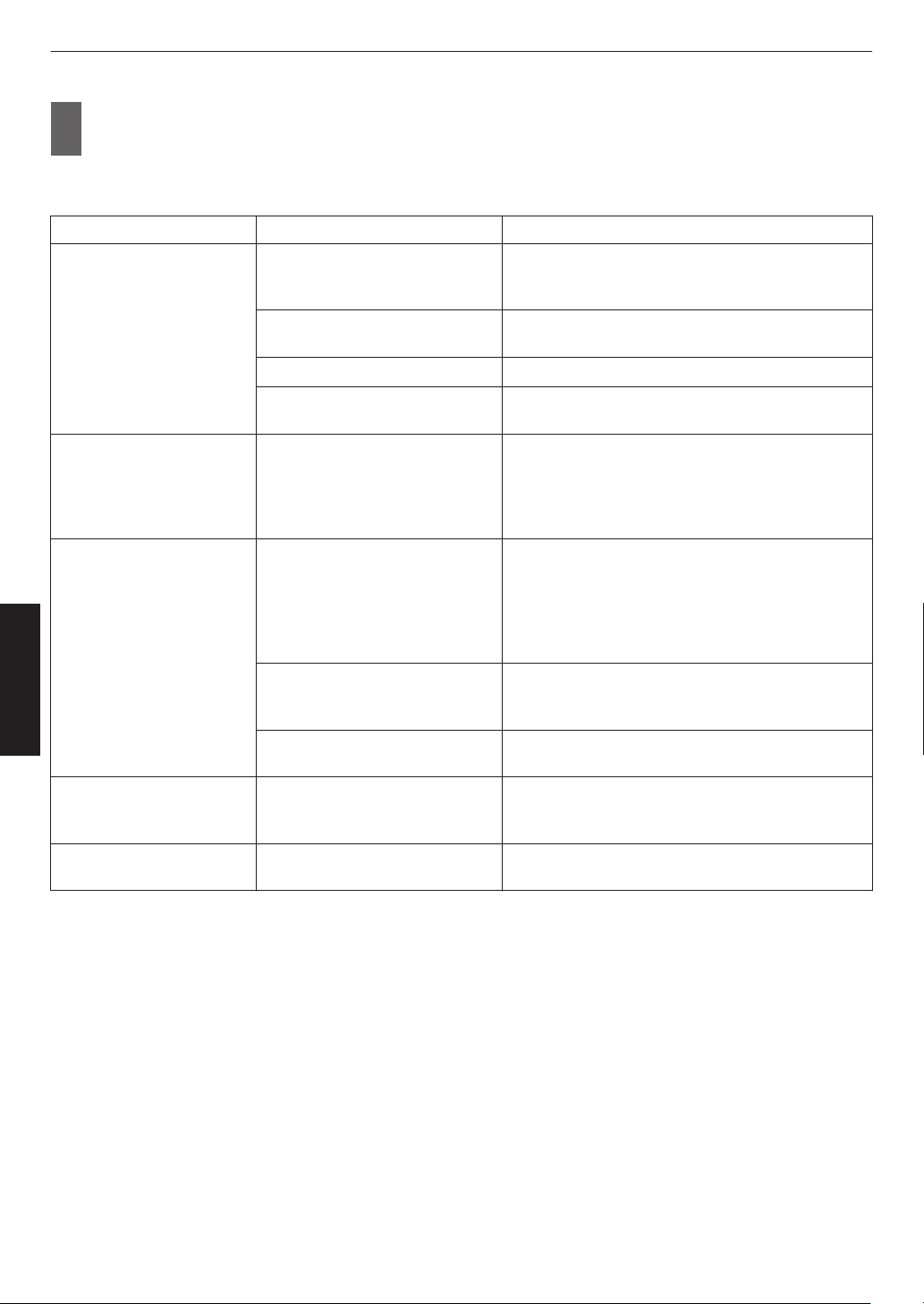
2
Press the [PICTURE MODE] button, use the [JK] keys
to select “Picture Mode” and
press [OK]
0
You can also perform the setting by pressing the [MENU] button to display the menu followed by selecting
“Picture Adjust” " “Picture Mode”.
Video Type (*) Available Picture Modes Description
SDR Natural Image quality that focuses on natural color and
gradation reproduction. Suitable for drama footage,
etc.
Cinema Reproduces the image in vivid colors. Suitable for all
movies.
Film x y 5 6 Reproduces faithfully the texture of movie films.
User 1 to User 3 Enables user-defined image quality data to be saved
and retrieved.
HDR10+ HDR10+ Picture mode suitable for viewing HDR10+ content.
Tone
mapping is optimally performed for each scene
according to the dynamic metadata to faithfully
reproduce HDR video images according to the
intentions of the video producer.
HDR10 Frame Adapt HDR Picture mode that analyzes and automatically
adjusts the HDR Tone Mapping of each frame in the
HDR10 content.
It employs an original analysis algorithm that allows
users to enjoy HDR10 content with different levels of
brightness in the optimal picture quality.
HDR10 Making full use of the wide color gamut and contrast,
this mode is suited for viewing HDR10 content such
as Ultra HD Blu-ray and streaming service.
Pana_PQ Picture mode used exclusively for Panasonic
UHDBD players.
HLG HLG Image quality suited for viewing content produced in
Hybrid Log-Gamma, a HDR standard for HLG
broadcasting.
HDR10/HLG User 4 to User 6 Enables user-defined image quality data to be saved
and retrieved.
* Video type that is automatically determined if Content Type is configured to Auto
40
Adjust/Set
Setting the Color Profile
By setting the “Color Profile” (color space information) according to the “Picture Mode”, you can fine-tune the image
quality according to the movie you are viewing.
*
When “Picture Mode” is set to “HDR10+”, the setting is fixed at BT.2020(Normal)
x y 5 6/“BT.
2020” z 4 7 8.
1
After configuring “Picture Mode” (P. 39), press the [COLOR PROFILE] button, use
the [JK] keys to select “Color Profile”, followed by pressing [OK]
0
You can also perform the setting by pressing the [MENU] button to display the menu followed by selecting
“Picture Adjust” " “Color Profile”.
0
The selectable “Color Profile” settings vary according to “Picture Mode”.
“Color Profile”
Color Profile Description
Auto
Switches the color profile automatically based on the color gamut information of
the input content.
BT.709 Color space that is suitable for BT.709.
BT.2020(Wide)
x y 5 6
Color space that is suitable for HDR viewing. The cinema filter is configured to Wide.
*1
BT.2020(Normal)
x y 5 6
Color space that is suitable for HDR viewing. The cinema filter is configured to Normal.
*1
BT.2020 z 4 7 8
Color space that is suitable for HDR viewing.
DCI Color space that is suitable for DCI.
Video
Color gamut that reproduces video footage such as dramas and live images in
bright and vivid colors.
Anime. x y 5 6
Color space that is suitable for CG animation works. Ideal for animated works with
bright colors.
Cinema
Cinema-specific color gamut that achieves a balance between increased
brightness and color vividness.
Film 1 x y 5 6
Color space that is close to the characteristics of Eastman Kodak Company movie
films.
Film 2 x y 5 6
Color space that is close to the characteristics of FUJIFILM Corporation movie
films.
Off (Wide)
x y 5 6
Disables color space adjustment. The cinema filter is configured to Wide.
*1
Off (Normal)
x y 5 6
Disables color space adjustment. The cinema filter is configured to Normal.
*1
Off z 4 7 8
Disables color space adjustment.
Pana_PQ_HL
*2
Use this option when the player display setting is configured to “High Luminance
Projector”.
Pana_PQ_BL
*2
Use this option when the player display setting is configured to “Basic Luminance
Projector”.
Custom1 to Custom4 For saving the color profile data created using the projector calibration software.
41
Adjust/Set
*1 Normal cinema
filter is a setting that prioritizes brightness and is best suited for video content or movies with an
apparent peak.
Wide cinema filter is a setting that prioritizes color reproduction and allows users to enjoy the wide color gamut
of HDR. Recommended for all kinds of movie content.
*2 Color profile for Panasonic UHD BD player only. For details on how to use these options, please refer to
P. 53.
List of selectable “Color Profile” according to “Picture Mode”
Picture Mode Color Profile
Natural
Cinema
Auto
BT.709
BT.2020(Wide) x y 5 6
BT.2020(Normal) x y 5 6
BT.2020 z 4 7 8
DCI
Video
Anime. x y 5 6
Cinema
Film x y 5 6 Film 1
Film 2
HDR10+
BT.2020(Normal) x y 5 6
*
BT.2020 z 4 7 8
*
Frame Adapt HDR BT.2020(Wide) x y 5 6
BT.2020(Normal) x y 5 6
BT.2020 z 4 7 8
HDR10
HLG
Auto
BT.709
BT.2020(Wide) x y 5 6
BT.2020(Normal) x y 5 6
BT.2020 z 4 7 8
DCI
Pana_PQ Pana_PQ_HL
Pana_PQ_BL
(Continue on next page)
42
Adjust/Set
Picture Mode Color Profile
User 1 to User 3 Auto
BT.709
BT.2020(Wide) x y 5 6
BT.2020(Normal) x y 5 6
BT.2020 z 4 7 8
DCI
Video
Anime. x y 5 6
Cinema
Off (Wide) x y 5 6
Off (Normal) x y 5 6
Off z 4 7 8
Custom1 to Custom4
User 4 to User 6 Auto
BT.709
BT.2020(Wide) x y 5 6
BT.2020(Normal) x y 5 6
BT.2020 z 4 7 8
DCI
Pana_PQ_HL
Pana_PQ_BL
Off (Wide) x y 5 6
Off (Normal) x y 5 6
Off z 4 7 8
Custom1 to Custom4
* When “Picture Mode” is configured to “HDR10+”, “Color Profile” is fixed at BT.
2020(Normal) x y 5 6/“BT.2020” z 4 7 8 and the color profile function cannot
be used.
43
Adjust/Set
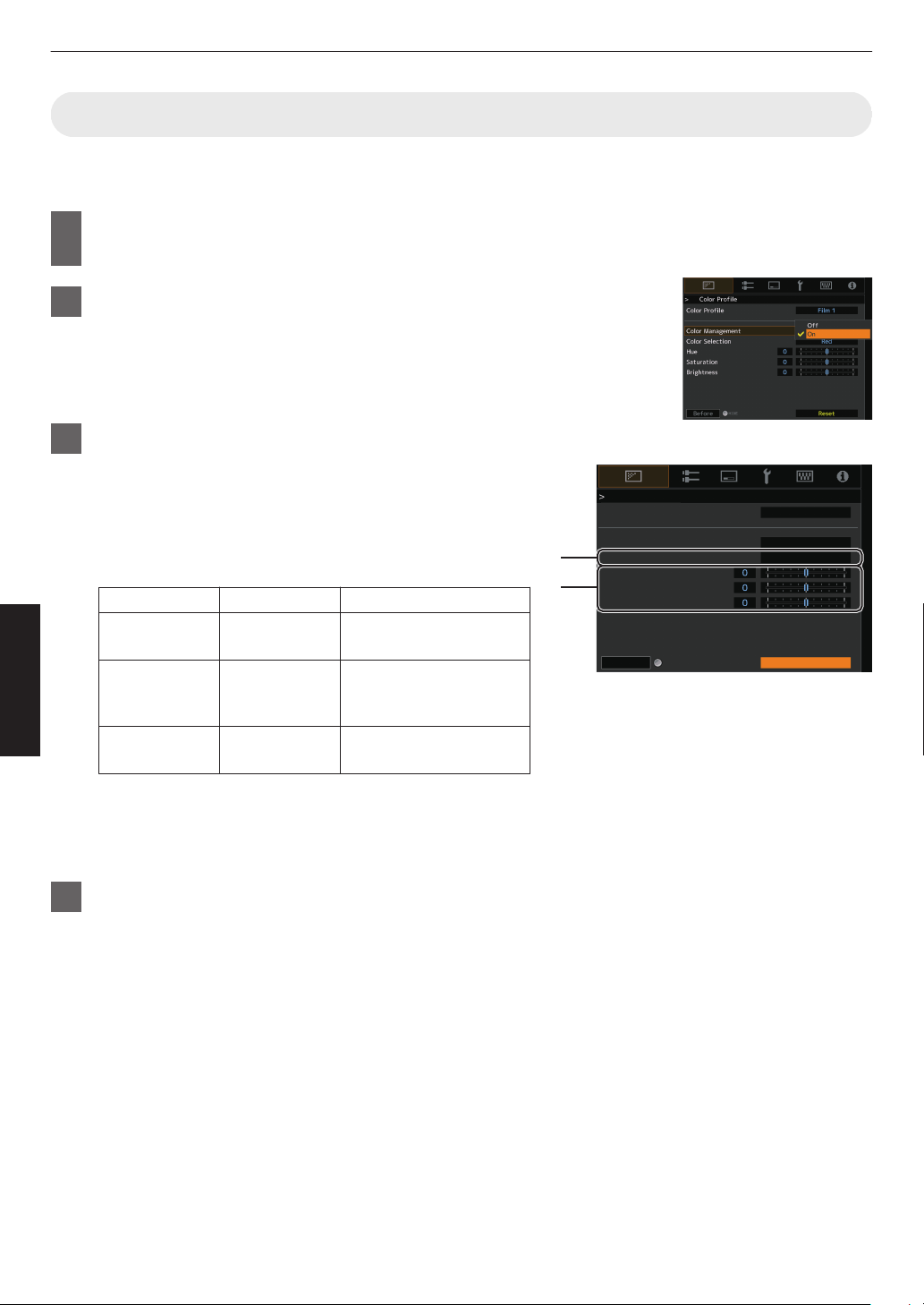
Adjusting to your Preferred Color (Color Management)
Based on the setting of the selected “Color Profile”, you can adjust each of the following colors according to your
preference: Red, Yellow, Green, Cyan, Blue, and Magenta.
1
Press the [MENU] button to display the menu, followed by selecting “Picture
Adjust” " “Color Profile” to display the “Color Profile” menu
2
Set “Color Management” to “On”, and press the [OK] button
3
Adjust to the preferred color
A
Select “Color
Selection”, and press the H I keys to select the
color to adjust
0
For color adjustment, select the color from the following:
“Red”, “Yellow”, “Green”, “Cyan”, “Blue”, “Magenta”.
B
Adjust the selected color
Item
Setting Range
Description
Hue -30 to 30 Adjusts the hue (color
tone).
Saturation -30 to 30 Adjusts the color
saturation (vividness).
-30 (dull) to +30 (vivid)
Brightness -30 to 30 Adjusts the brightness.
-30 (dark) to +30 (bright)
0
Selecting “Reset” resets all the adjustment data.
0
Pressing the
[HIDE] button on the remote control enables
you to check the image before adjustment. Press the
[HIDE] button again to return to the adjustment screen.
4
Press the [MENU] button to exit
A
B
Color Profile
Color Profile
Color Management
Color Selection
Hue
Saturation
Brightness
Before
Reset
Film 1
Red
On
HIDE
44
Adjust/Set
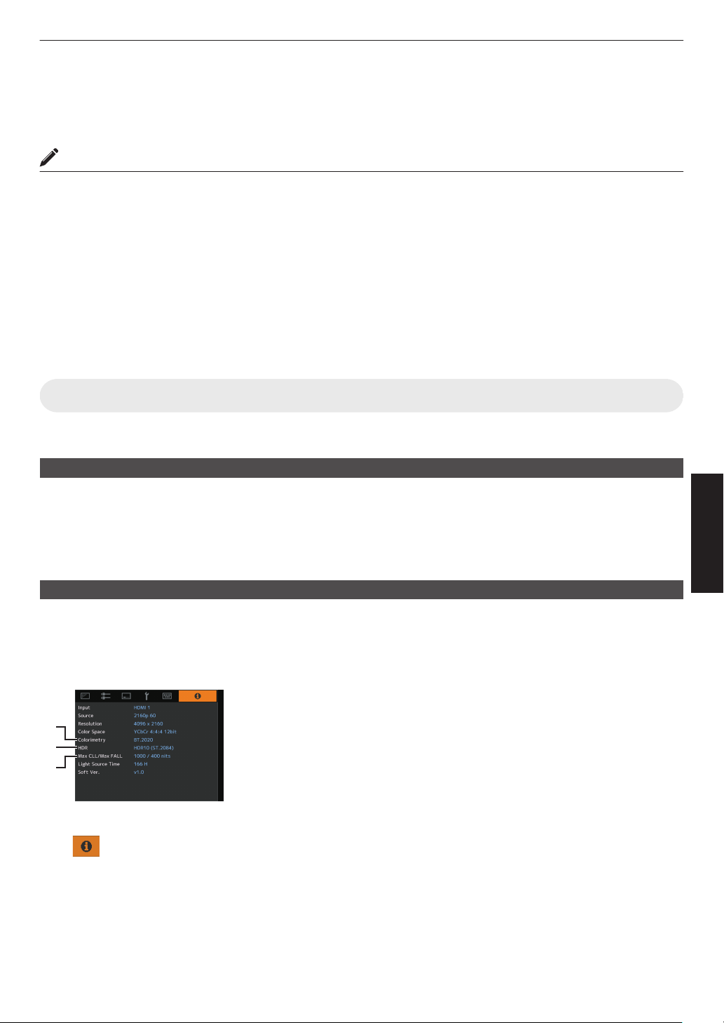
Viewing HDR Content
When viewing HDR content, making adjustments according to the content and viewing environment allows the images
to be played back in higher quality.
What is HDR content?
HDR (High Dynamic Range) refers to images with a significant difference in brightness between the highlight and
shadow areas (dynamic range). It is a technology that enables faithful and realistic reproduction of the original colors
as well as glitter and details of shadows that could not be expressed by the conventional SDR (Standard Dynamic
Range). The international standard for HDR is set forth in the ITU-R (International Telecommunication Union –
Radiocommunication Sector)
BT.2100. Enhancements have been made in many aspects compared to ITU-R BT.709,
which was the conventional Full HD standard.
HDR can largely be divided into two different formats, namely HDR10 which is employed by UHD-BD and video
streaming services, and Hybrid Log-Gamma which is employed for broadcasting. Compared to the conventional SDR,
the standard HDR format HDR10 delivers a higher resolution, higher luminance and higher gradation as well as a wider
color gamut to reproduce images more realistically in combination with the wide dynamic range. HDR10+, which is an
extension of the HDR10 standard, embeds brightness information for each scene into the content as metadata. This
allows tone mapping based on the scene, and makes it possible to faithfully reproduce the HDR video according to the
intention of the producer.
Æ “HDR Feature on This Unit” (P.
45
)
HDR Feature on This Unit
This unit is equipped with features for enjoying HDR images in better quality with ease.
Content Type
HDR format contents cannot be displayed correctly unless it is viewed in the appropriate picture mode. Configuring
“Content Type”
to “Auto” on this unit enables selection of only the “Picture Mode” suited for the content. Doing so allows
users to enjoy optimal HDR videos without the need to deal with the complex settings.
* The picture mode might not switch automatically depending on the playback content and player in use.
Æ “Content Type” (P. 64)
HDR10 Mastering Information Display
Mastering information contained in the content can be displayed when playing HDR10 content such as those on UHD
Blu-ray. With
this information, you can be sure that HDR content is being played back. Also, based on the information
of Max CLL and Max FALL, customized changes according to the content can be performed by adjusting the picture
tone.
* Mastering information might not be displayed depending on the playback content and player in use.
A
Colorimetry
Displays the color gamut information of the input signals.
B
HDR
Displays the gamma information when HDR packet is received.
C
Max CLL/Max FALL
Displays the mastering information of the content during HDR playback.
Max CLL: Maximum Content Light Level
Max FALL: Maximum Frame Average Light Level
Æ “
Information” (P. 90)
A
B
C
45
Adjust/Set
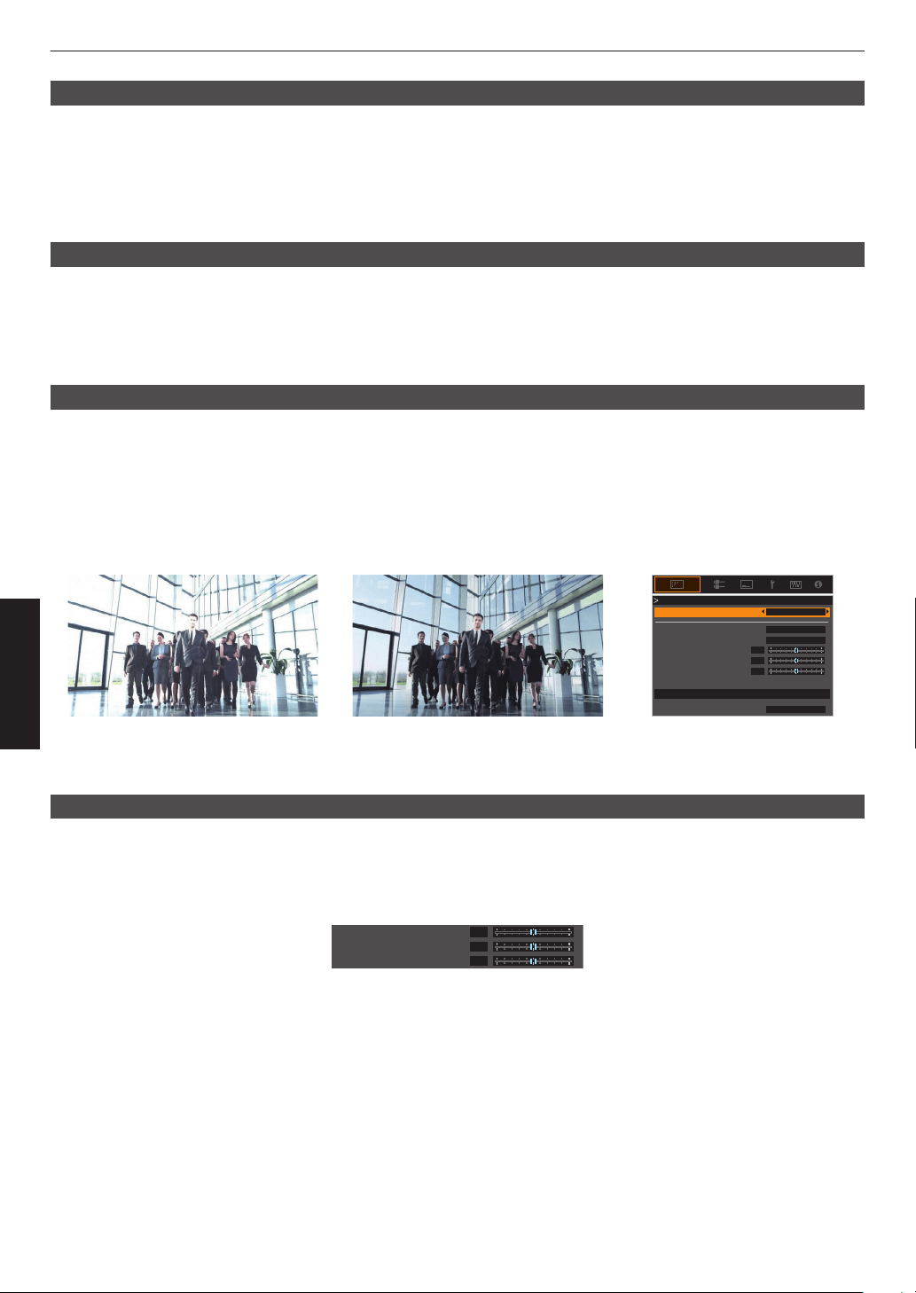
Frame Adapt HDR (Dynamic Tone Mapping)
Each HDR movie or title is designed for peak brightness that will change from scene by scene or frame by frame.The
“Frame Adapt
HDR” feature enables the HDR tone mapping to be adjusted in real time automatically. This feature does
not require any mastering information, it will analyze each frame of the HDR image in real time to achieve the almost
same mastering information as the original director’s cut. This feature works across all HDR platforms from streaming
devices to 4K UHD players.
Æ “Setting Frame Adapt HDR” (P. 47)
Theater Optimizer
The brightness of the projector screen varies not only with the screen size, gain and projection distance but also with
the frequency of use and various settings. When “Picture Mode” is configured to “Frame Adapt HDR”, the “Theater
Optimizer” function
automatically analyzes the environment in which the projector is used and adjusts the tone mapping
to allow viewing in the appropriate brightness according to the details of the screen entered in advance. This allows
you to enjoy HDR video optimized for your personalized usage environment.
Auto Tone Mapping
Grading varies diversely with the video work, with some content being made brighter and others darker. By configuring
“Tone Mapping”
to “HDR(Auto)”, gamma adjustment is performed automatically to achieve the optimal brightness based
on the mastering information (Max CLL/Max FALL) contained in the HDR10 content. Also, by configuring the base
brightness level in “Mapping Level”, you can enjoy the optimal picture quality according to the screen size and viewing
environment.
* This feature may not be available depending on the playback content and player in use.
Æ “Adjusting Tone Mapping Automatically (Per Movie or Title)” (P. 50)
0
0
0
White
Bright Level
Dark Level
Picture Tone
Color Selection
---
Correction Value
Reset
Max CLL/Max FALL 1000 / 400 nits
Tone Mapping
Tone Mapping HDR(Auto)
Fixed Tone Mapping Tone Mapping“HDR(Auto)”
* The photos are for illustrative purposes only.
Manual Tone Mapping Adjustment
In addition to the “Auto Tone Mapping” function, tone mapping adjustment can also be performed manually on this unit.
Fine-tuning according
to the playback content and viewing environment is possible by using “Picture Tone” to determine
the overall brightness, “Dark Level” to adjust the gradation of shadows, and “Bright Level” to adjust the gradation of
highlights.
Æ “Performing Tone Mapping Manually” (P. 51)
0
0
0
Bright Level
Dark Level
Picture Tone
46
Adjust/Set

Viewing HDR10+ Content
1
Press the [MENU] button to display the menu, and set “Content Type” to “Auto” or
“HDR10+” in the “Picture Adjust” menu.
2
Enter the HDR10+ content.
0
When
“Input
Signal” " “HDMI EDID Setting” " “HDR10+” is configured to “Off”, the receiving of HDR10+ is disabled.
To enjoy HDR10+ content, configure to “On”. (“HDMI EDID Setting”P. 76)
Setting Frame Adapt HDR
1
Press the [MENU] button to display the menu, and set “Content Type” to “Auto” or
“HDR10” in the “Picture Adjust” menu.
2
Configure “Picture Mode” to “Frame Adapt HDR” in the “Picture Adjust” menu.
0
You can also press the [PICTURE MODE] button and use the ↑↓ keys “Frame Adapt HDR” to select and
configure a setting. (P.
39)
0
Enter the HDR10 content when “Picture Mode” is configured to “Auto”.
3
Configure to “HDR Processing” in the “Picture Adjust” menu.
(“HDR Processing”P. 70)
*
4
Configure to “HDR Level” in the “Picture Adjust” menu.
(“HDR Level”P. 71)
*
* This can be configured only when “Picture Mode” is configured to “Frame Adapt HDR”.
MEMO
0
If you wish to watch HDR10 content in the “Frame Adapt HDR” picture mode, we recommend that you enable
automatic switching to “Frame Adapt HDR” in “Input Signal”"“Auto Pic.Mode Select”"“HDR10”. (“Auto Pic.Mode
Select”P.
75)
0
Configuring “Theater
Optimizer” to “On” enables “HDR Level” to be configured automatically according to the screen
size and state of the projector. (“Theater Optimizer”P. 71)
47
Adjust/Set
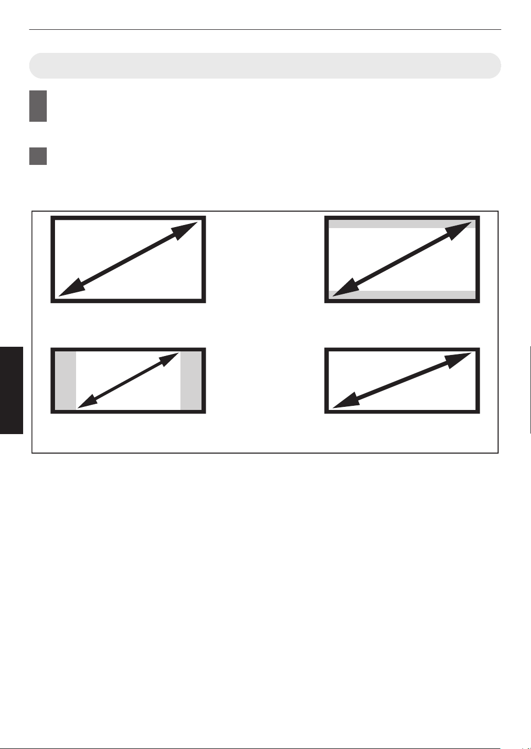
Using the “Theater Optimizer”
1
Press the [MENU] button to display the menu, followed by selecting “Installation” "
“Screen Setting” to display the “Screen Setting” menu.
0
You can also display the menu by selecting “Screen Setting” from the “Theater Optimizer” menu.
2
Select “Screen Size(Diagonal)” to configure the size of the screen in use.
0
This configures the size of the screen for viewing when using “Theater Optimizer”. However, to project an
image with an aspect ratio other than 2.35:1 on a 2.35:1 screen, configure the size of the projected image.
Example on configuring the screen size
To project a 16:9 image on a 16:9
screen
Configure the size of the screen.
(a)
(c)
To project a 2.35:1 image on a 16:9
screen
Configure the size of the screen.
(b)
To project a 16:9 image on a 2.35:1
screen
Configure the size of the projected image.
To project a 2.35:1 image on a 2.35:1
screen
Configure the size of the screen.
(d)
48
Adjust/Set

3
Select “Screen Aspect” to configure the aspect ratio of the screen in use.
4
Select “Screen Gain” to configure the gain of the screen in use.
5
Set “Picture Mode” to “Frame Adapt HDR” (“Setting the Picture Mode”P. 39)
6
Select “Picture Adjust” " “Theater Optimizer” to display the “Theater Optimizer”
menu.
0
You can also display the menu by selecting “Theater Optimizer” from the “Screen Setting” menu.
*1 This option does not appear in the menu when “Content Type” is configured to “SDR”.
*2
This can be configured only when
“Picture Mode” is configured to “Frame Adapt HDR”.
7
Set “Theater Optimizer” to “On”
8
Press “Set”.
The details of the screen is applied to the “Theater Optimizer” adjustment.
CAUTION
To use “Theater Optimizer”, configure the details of the screen in use in “Screen Setting”, followed by pressing “Set”.
Pressing “Set” in the “Theater Optimizer” menu automatically applies the “Screen Setting” settings and state of the
projector in the auto settings of “Theater Optimizer”.
If
“Set”
is not pressed in the “Theater Optimizer” menu, the settings are applied after the next restart of the unit or change
of the “Installation Mode”.
49
Adjust/Set

Adjusting Tone Mapping Automatically (Per Movie or Title)
1
Press the [MENU] button to display the menu, and set “Content Type” to “Auto” or
“HDR10” in the “Picture Adjust” menu.
2
Configure “Picture Mode” to “HDR10” or “User 4 to User 6” in the “Picture Adjust”
menu.
0
Alternatively, press the [PICTURE MODE] button and use the ↑↓ keys to configure a setting. (
P.
39)
0
Enter the HDR10 content when “Content Type” is configured to “Auto”.
3
Press “Tone Mapping” in the “Picture Adjust” menu to display the Tone Mapping
menu, followed by configuring “Tone Mapping” to “HDR(Auto)”. Alternatively,
configure “Tone Mapping” to “Custom 1 to Custom 3”, followed by configuring
“Correction Value” to “HDR(Auto)”.
4
Configure to “Mapping Level” in the “Picture Adjust” menu.
*
* This may not appear depending on the settings. Please refer to “Mapping Level”P. 72 for details.
MEMO
When “Correction Value” is configured to “HDR(Auto)” while “Tone Mapping” is configured to “HDR(Auto)” or “Tone
Mapping” configured
to “Custom 1 to Custom 3”, “Picture Tone”“Dark Level”“Bright Level” may also be adjusted but the
changes will not be saved.
To fine-tune the settings, configure “Tone Mapping” to “HDR(PQ)” and set manually.
Æ “Performing Tone Mapping Manually” (P. 51)
50
Adjust/Set
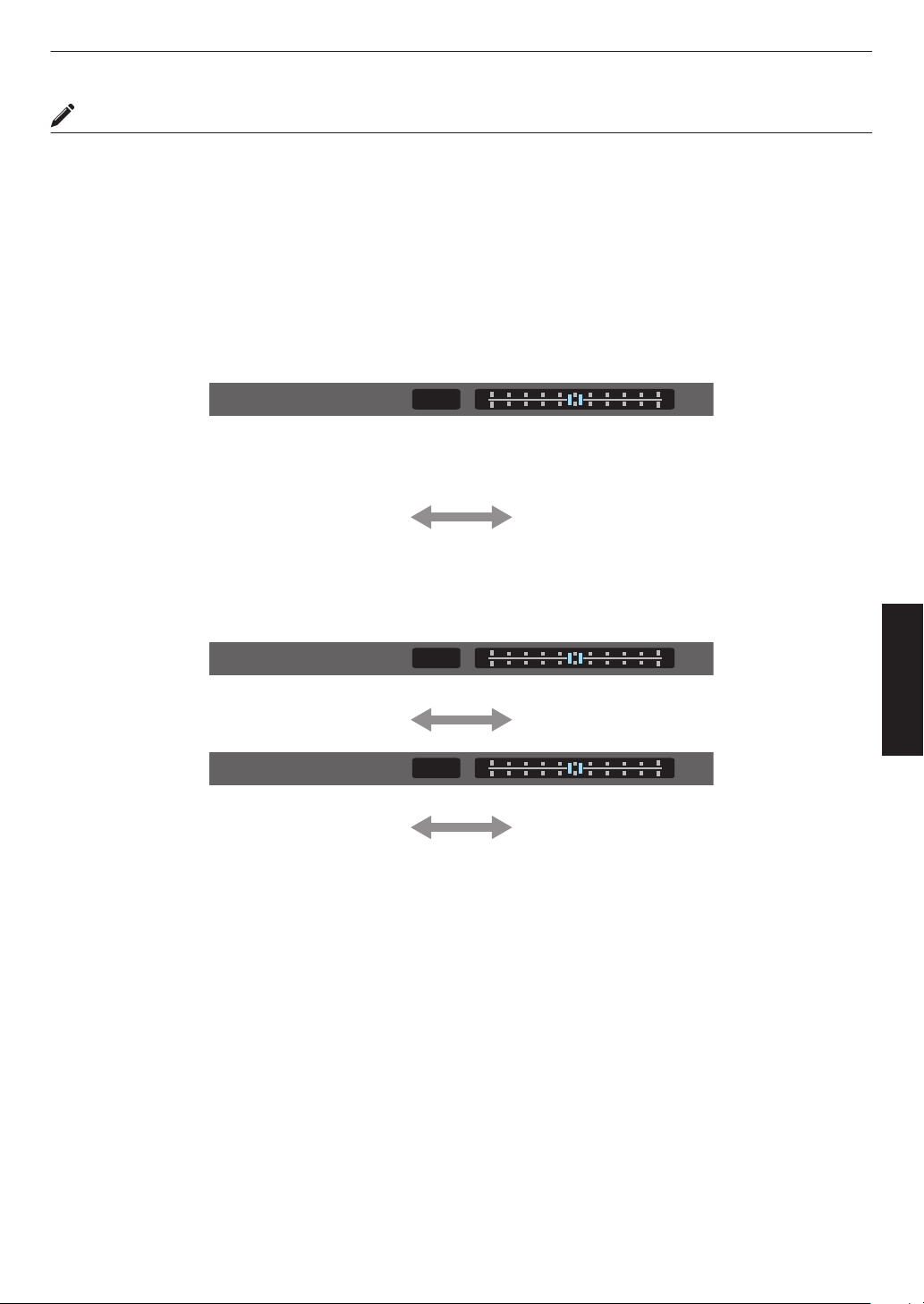
Performing Tone Mapping Manually
“HDR(PQ)” gamma is the PQ curve adopted by HDR10. Fine adjustments can be made according to the screen size
and environment although the default settings for viewing with the projector have been adjusted to allow optimum
viewing.
Default settings when viewing HDR content of this projector
Picture Mode : HDR10
Tone Mapping
:
HDR(PQ)
Estimated Screen Size : 90 to 120 inch (screen gain 1.0)
Estimated MaxCLL/
MaxFALL
: MaxCLL 1000 nits, MaxFALL 400 nits
Picture tone adjustment method
0
Picture Tone
When Picture Tone is set to “-”
(The entire screen becomes dark.)
0
Screen size is smaller than estimated
0
MaxFALL/MaxCLL value is higher than
estimated (P.
90)
0
Screen becomes brighter in the course of
viewing
When Picture Tone is set to “+”
(The entire screen becomes brighter.)
0
Screen size is bigger than estimated
0
MaxFALL/MaxCLL value is lower than
estimated (
P. 90
)
0
Screen becomes darker in the course of
viewing
Bright/dark area adjustment method
0
Dark Level
(―) To enhance the contrast
(+) To make the dark area information more
visible
0
Bright Level
(―) To enhance the gradation of highlight areas (+) To enhance the contrast
51
Adjust/Set
For users seeking to obtain a gamma curve that is more faithful to the original PQ curve
This unit has been adjusted to display the projector images on the screen in the optimal quality in the default setting
based on
the original PQ curve. For users who wish to obtain results more faithful to the original PQ curve, please adjust
manually with reference to the values below.
When clipping point is 400 nits
Picture Tone +5
Dark Level 0
Bright Level +7
When clipping point is 1000 nits
Picture Tone -7
Dark Level 0
Bright Level +7
When clipping point is 2000 nits
Picture Tone -9
Dark Level 0
Bright Level +7
When clipping point is 4000 nits
Picture Tone -13
Dark Level 0
Bright Level +7
* This product is designed for home use and we do not provide guarantee for commercial uses such as in mastering
work.
52
Adjust/Set
Collaboration with Panasonic UHD BD Player DP-UB9000
Selecting one of two special projector color profiles from the HDR Display Type of the DP-UB9000 enhances
dimensionality and improves gradation accuracy by tone mapping HDR video to match the JVC projector display
characteristics.
Step 1:
Using Panasonic DP-UB9000: Select “High Luminance Projector” or “Basic Luminance Projector” from HDR Display
Type Setting.
Step 2:
Using Panasonic DP-UB9000: Set HDR Optimizer “On” from OSD menu.
Step 3:
Using JVC Projector: Set “Picture Mode” as follows.
1
Set “Picture Mode” to “Pana_PQ” (P. 39)
2
Set “Color Profile” (P. 41) manually based on the following chart
Projector Color Profile
DP-UB9000
HDR Display Type
Effects on the Video Image
Pana_PQ_HL High Luminance Projector Prioritizes highest image brightness with good color.
Pana_PQ_BL Basic Luminance Projector Prioritizes best color reproduction with slightly reduced
brightness.
* The gamma settings for HDR are included in the color profile. Please configure the projector according to the above.
3
Configure “Color Temp.” to “6500K” (P. 67) and “Tone Mapping” to “Pana_PQ”
(P. 54)
MEMO
0
To watch
HDR10 content in the preconfigured “Pana_PQ” picture mode, it is recommended that you configure “Input
Signal”"“Auto Pic.Mode Select”"“HDR10” to “Pana_PQ”. (“Auto Pic.Mode Select”P. 75)
53
Adjust/Set
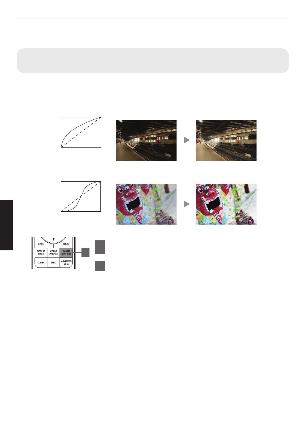
Fine-tuning the Image Quality
Adjusting the Output Value of the Projected Image (Gamma/Tone
Mapping)
You can adjust the output value of the projected image with respect to the video signal input.
* This item is not available when “Picture Mode” is set to “Frame Adapt HDR”/“HDR10+”.
Example of gamma adjustment
The overall image appear brighter with respect to the original image, making the dark areas more visible.
0
255
0 255
The photos are for illustrative purposes only.
Input Value
Output Value
A
B
AB
Increases the contrast with respect to the original image, creating a greater sense of depth.
0
255
0 255
A
B
AB
The photos are for illustrative purposes only.
Input Value
Output Value
1
Press the [GAMMA SETTINGS] button to display the
Gamma/Tone Mapping menu
2
Select the “Gamma/Tone Mapping” to configure
0
You can also perform the setting by pressing the [MENU] button to display
the
menu
followed by selecting “Picture Adjust” " “Gamma/Tone Mapping”.
0
The selectable
“Gamma/Tone Mapping” settings vary according to “Picture
Mode”.
1
54
Adjust/Set
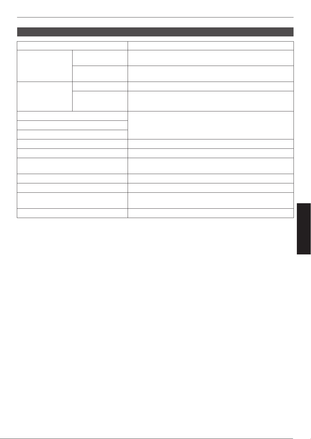
“Gamma/Tone Mapping” Settings
Gamma/Tone Mapping Description
When “Color Profile” is
set to “Film 1”
x y 5
6
Film 1 Image is close to the characteristics of Eastman Kodak Company
movie films.
Film 2 Places more emphasis on the gradation compared to the “Film 1”
setting.
When “Color Profile” is
set to “Film 2”
x y 5
6
Film 1 Places more emphasis on the contrast compared to the “Film 2” setting.
Film 2 Image is close to the characteristics of FUJIFILM Corporation movie
films.
2.2 The gamma is set to “2.2”, “2.4” and “2.6” respectively.
2.4
2.6
Cinema 1 Places emphasis on the gradation.
Cinema 2 Places emphasis on the contrast.
HDR(Auto) Automatically corrects “Picture Tone”“Dark Level”“Bright Level” from
Max CLL/Max FALL with “HDR(PQ)” as the base.
HDR(PQ) Suited for viewing HDR content such as UHD BD (HDR10).
HDR(HLG) Suited for viewing HDR content such as HDR broadcast.
Pana_PQ Tone mapping used exclusively for Panasonic UHDBD players. For
details on how to use this option, please refer to
P.
53.
Custom 1 to Custom 3 Enables fine adjustment of gamma according to preference.
55
Adjust/Set
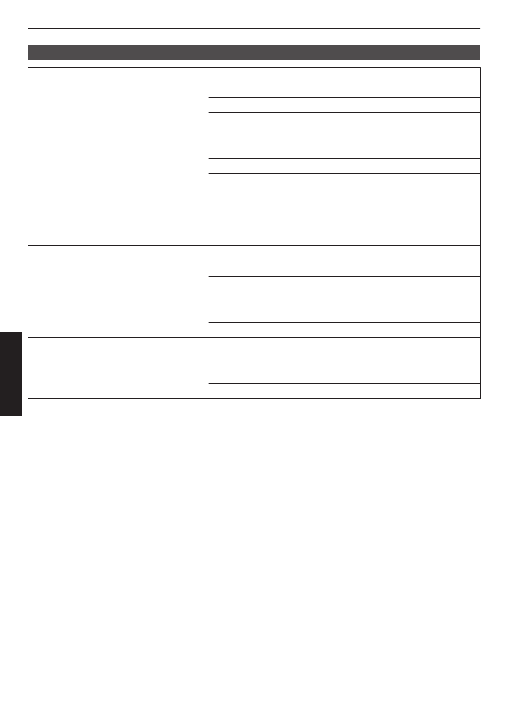
List of Selectable “Gamma/Tone Mapping” According to “Picture Mode”
Picture Mode Gamma/Tone Mapping
Film x y 5 6 Film 1
Film 2
Custom 1 to Custom 3
Cinema
Natural
User 1 to User 3
2.2
2.4
2.6
Cinema 1
Cinema 2
Custom 1 to Custom 3
HDR10+
Frame Adapt HDR
HDR(Auto)
*
HDR10 HDR(Auto)
HDR(PQ)
Custom 1 to Custom 3
Pana_PQ Pana_PQ
HLG HDR(HLG)
Custom 1 to Custom 3
User 4 to User 6 HDR(Auto)
HDR(PQ)
HDR(HLG)
Custom 1 to Custom 3
* When “Picture Mode” is configured to “Frame Adapt HDR”/“HDR10+”, this is fixed at “HDR(Auto)” and “Gamma/
Tone Mapping” cannot be configured.
56
Adjust/Set
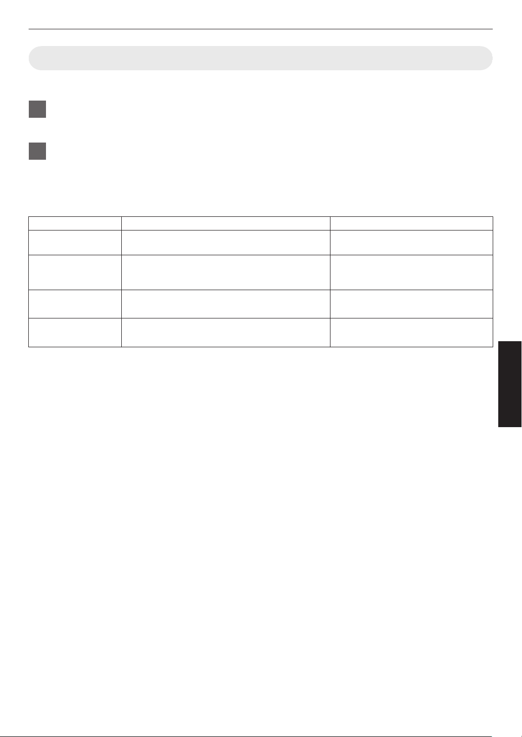
Fine-tuning of Gamma/Tone Mapping to Preferred Settings
You can perform fine adjustments based on the selected gamma adjustment setting.
1
Press the [GAMMA SETTINGS] button to display the Gamma/Tone Mapping menu
0
You can also perform setting from “Picture Adjust”"Gamma/Tone Mapping in the menu.
2
Adjust to the preferred setting
0
Select the color to be adjusted from “Color Selection” and adjust the “Picture Tone”, “Dark Level” and “Bright
Level”.
Adjustment item and its setting
Item Description Setting
Color Selection For selecting the color for adjusting “Picture Tone”,
“Dark Level” and “Bright Level”.
White / Red / Green / Blue
Picture Tone Adjusts the overall brightness automatically for a
well-balanced result without compromising the
gradation of the image.
-16 (darkens image for an underexposed
effect) to +16 (brightens image for an
overexposed effect)
Dark Level Adjusts the dark areas of the input image.
0
To do so, use the H I keys to move the cursor.
-7 (darkens the shadows) to +7
(brightens the shadows)
Bright Level Adjusts the bright areas of the input image.
0
To do so, use the H I keys to move the cursor.
-7 (darkens the highlights) to +7
(brightens the highlights)
57
Adjust/Set
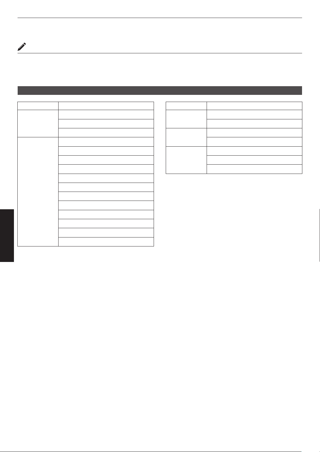
Selecting the Base Correction Value (Initial Value) for Adjustment
0
Selecting one of the “Custom 1” to “Custom 3” settings in “Gamma” allows you to select the “Correction Value”.
0
Select the base “Correction Value” for adjustment using the H I keys.
0
The selectable correction values vary according to “Picture Mode”. (Refer to the table below.)
List of selectable “Correction Value” according to “Picture Mode”
Picture Mode Correction Value
Film
x y
5 6
Film 1
Film 2
Import
Cinema
Natural
User 1
to User 3
1.8
1.9
2.0
2.1
2.2
2.3
2.4
2.5
2.6
Cinema 1
Cinema 2
Import
Picture Mode Correction Value
HDR10 HDR(PQ)
Import
HLG HDR(HLG)
Import
User 4 to User 6 HDR(PQ)
HDR(HLG)
Import
* Correction value cannot be configured when “Picture Mode” is configured to “Frame Adapt HDR”/“HDR10+”.
When “Correction Value” is set to “Import”
0
By selecting
“Import” for “Correction Value”, the gamma data created externally can be selected as the base setting
value for adjustment.
0
The factory setting for “Import” is “2.2”.
0
You
can
use the calibration software to customize the gamma data adjustment, and import the created gamma data.
Please check with your authorized dealer for details.
58
Adjust/Set
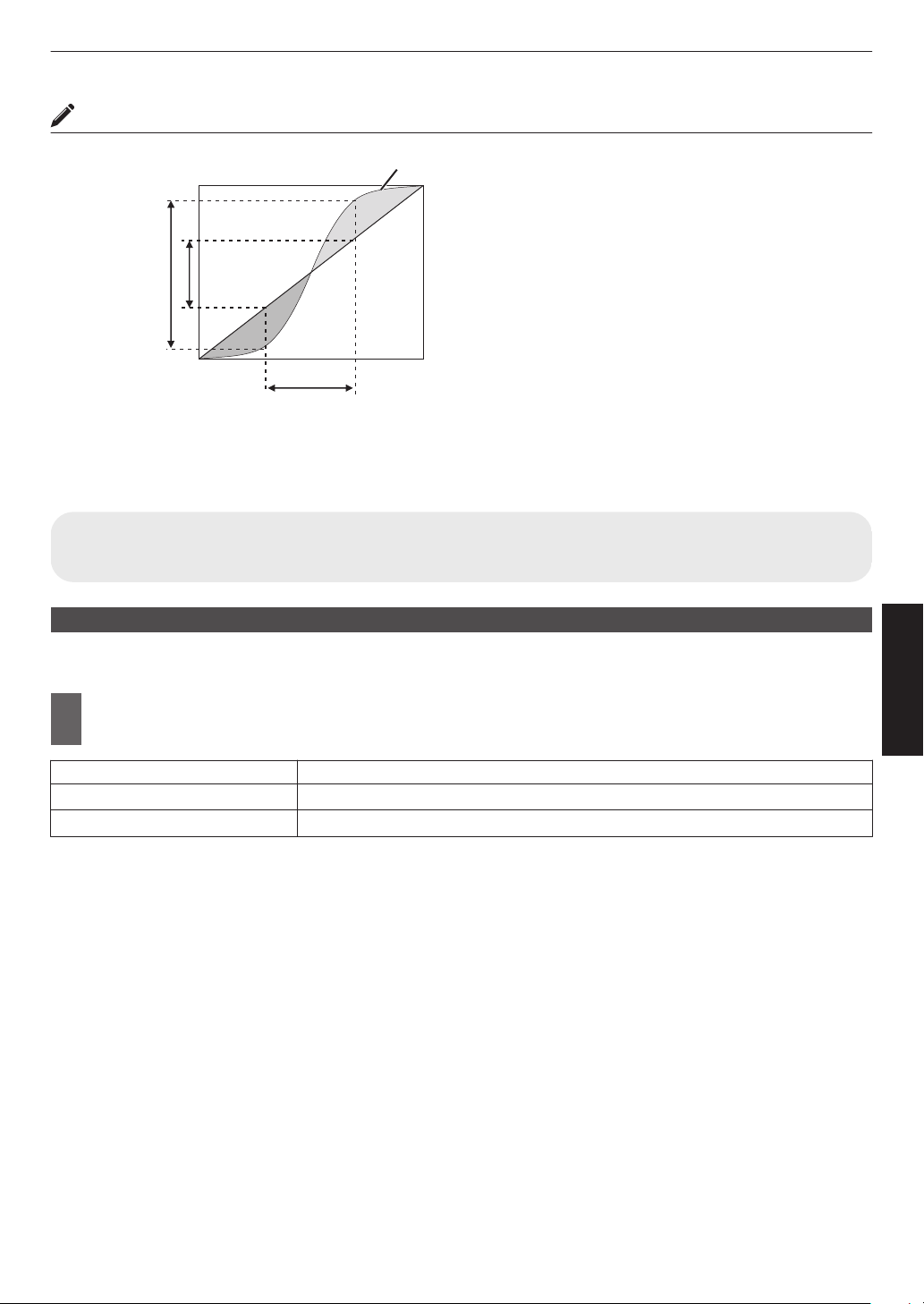
Gamma Adjustment
0
When the gamma curve is a straight line:
The brightness and contrast of the video input will be
the same as that of the video output.
0
Area for which the gamma curve is above the straight
line (A):
Video output appears brighter than the input.
0
Area for which the gamma curve is below the straight
line (B):
Video output appears darker than the input.
0
Area for which the slope of the gamma curve is steep
(midtone) (C):
The grayscale range of the video output becomes
wider, and the contrast increases (D"D’).
C
B
A
D
0 255
0
255
D”
Gamma Curve
Input Value
Output Value
Dark
Dark
Bright
Bright
Reducing the Delay and After-image of Fast-moving Images (Motion
Control)
Low Latency
For changing the low latency setting.
You are recommended to set to “On” for content requiring short latency such as games.
1
Press the [MENU] button to display the menu and select “Picture Adjust”"“Motion
Control”"“Low Latency”
Setting Description
Off Does not perform the low latency setting.
On Performs the low latency setting.
* “Low Latency” cannot be set when “Picture Mode” is set to “HDR10+”/“Frame Adapt HDR”.
* “Low Latency” cannot be configured when “Dynamic CTRL” is configured to a setting other than “Off”.
x
y z 5 6 7
* “Low Latency” cannot be configured when “Aperture” is configured to a setting other than “Manual”. 4 8
* “Clear Motion Drive” cannot be set when “Low Latency” is set to “On”.
* Even when “Low Latency” is set to “On”, delay will not become zero.
59
Adjust/Set
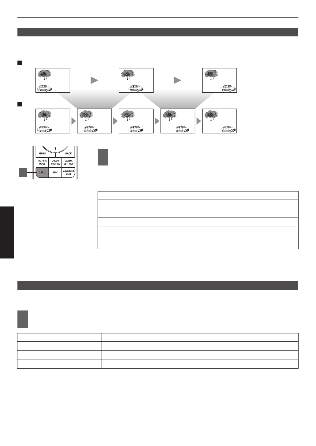
Clear Motion Drive (C.M.D.)
Optimal interpolation according to the content is made possible with the new high-definition image interpolation
technique.
For some scenes, interpolation may cause distortion in the image. In this case, set to “Off”.
Intermediate Frame GenerationIntermediate Frame Generation
Interpolation Enabled
Original Image
1
Press the [C.M.D.] button, use the [JK] keys to select a
setting, followed by pressing [OK]
0
You can also perform the setting by pressing the [MENU] button to display
the menu followed by selecting “Picture Adjust”"“Motion Control”"“Clear
Motion Drive”.
Setting Description
Off Interpolation is not performed.
Low Improves motion lag for movie type images.
High Improves motion lag fast moving sports type images.
Inverse Telecine 60i/60p video images such as those of TVs and DVDs.
Suitable for
original images that are 24-frame film sources.
0
Does not function for 24p video images.
* C.M.D. is the abbreviation for Clear Motion Drive.
* This item cannot be set when “Low Latency” is set to “On”.
*
This item cannot be configured when the input signal is 100Hz/120Hz.
Motion Enhance
You can reduce motion blur with this function enhancing the response of D-ILA image devices.
If the image outline is unnatural, set this item to “Off”.
1
Press the [MENU] button to display the menu and select “Picture Adjust”"“Motion
Control”"“Motion Enhance”
Setting Description
Off Does not perform correction.
Low Decreases jitter for fast moving video.
High Further reduces image blurring than “Low”.
1
60
Adjust/Set

Adjustments and Settings in the Menu
Pressing the [MENU] button displays the menu.
Press the [JKH I] keys to select an item, followed by pressing the [OK] button to confirm the selection.
List of Menu Items
Picture Adjust
IContent Type .................................................................................................................................................... P.
64
IPicture Mode .................................................................................................................................................... P. 39
IMore Settings ................................................................................................................................................... P. 64
9 LD Power x y z 5 6 7 ...................................................................................... P. 64
9 Lamp Power 4 8 ........................................................................................................................... P. 64
9 Dynamic CTRL x y z 5 6 7 .............................................................................. P. 65
9 Aperture ...................................................................................................................................................... P. 65
9 Contrast ...................................................................................................................................................... P. 66
9 Brightness ................................................................................................................................................... P. 66
9 Color ........................................................................................................................................................... P. 66
9 Tint .............................................................................................................................................................. P. 66
9 User Name Edit ........................................................................................................................................... P. 66
IColor Profile ...................................................................................................................................................... P. 41
9 Color Management ...................................................................................................................................... P. 44
9 Color Selection ............................................................................................................................................ P. 67
9 Hue ............................................................................................................................................................. P. 67
9 Saturation .................................................................................................................................................... P. 67
9 Brightness ................................................................................................................................................... P. 67
IColor Temp. ...................................................................................................................................................... P. 67
9 Correction Value ......................................................................................................................................... P. 69
9 Gain Red / Gain Green / Gain Blue .............................................................................................................. P. 69
9 Offset Red / Offset Green / Offset Blue ....................................................................................................... P. 69
IHDR Processing ............................................................................................................................................... P. 70
IGamma/Tone Mapping ..................................................................................................................................... P. 54
9 Correction Value ......................................................................................................................................... P. 70
9 Picture Tone ................................................................................................................................................ P. 57
9 Dark Level / Bright Level ............................................................................................................................. P. 57
ITheater Optimizer ............................................................................................................................................. P. 71
IHDR Level ........................................................................................................................................................ P. 71
IMapping Level .................................................................................................................................................. P. 72
IMPC/e-shift x y z 5 6 7, MPC Level 4 8 ................................................ P. 73
9 8K e-shift x y z 5 6 7 ....................................................................................... P. 73
9 Graphic Mode ............................................................................................................................................. P. 73
9 Enhance ...................................................................................................................................................... P. 73
9 NR ............................................................................................................................................................... P. 73
9 BNR ............................................................................................................................................................ P. 73
9 MNR ............................................................................................................................................................ P. 73
IMotion Control .................................................................................................................................................. P. 59
9 Low Latency ................................................................................................................................................ P. 59
9 Clear Motion Drive ....................................................................................................................................... P. 60
9 Motion Enhance .......................................................................................................................................... P. 60
61
Adjust/Set

Input Signal
IInput Level ........................................................................................................................................................ P.
74
IColor Space ...................................................................................................................................................... P. 74
I3D Setting ......................................................................................................................................................... P. 37
IAuto Pic.Mode Select ....................................................................................................................................... P. 75
9 SDR(2D)/ SDR(3D) ..................................................................................................................................... P. 75
9 HDR10 ........................................................................................................................................................ P. 75
9 HLG ............................................................................................................................................................. P. 75
IHDMI EDID Setting ........................................................................................................................................... P. 76
9 Mode ........................................................................................................................................................... P. 76
9 DSC ............................................................................................................................................................ P. 76
9 HDR10+ ...................................................................................................................................................... P. 76
Installation
IInstallation Mode .............................................................................................................................................. P.
77
9 Mode Select ................................................................................................................................................ P. 77
9 Name Edit ................................................................................................................................................... P. 77
9 Mode Copy .................................................................................................................................................. P. 77
ILens Control ..................................................................................................................................................... P. 35
9 Focus / Zoom / Shift .................................................................................................................................... P. 78
9 Image Pattern .............................................................................................................................................. P. 78
9 Lock ............................................................................................................................................................ P. 78
9 Lens Center ................................................................................................................................................. P. 78
IPixel Adjust ....................................................................................................................................................... P. 79
9 Adjust .......................................................................................................................................................... P. 79
9 Adjust Area .................................................................................................................................................. P. 79
9 Adjust Color ................................................................................................................................................. P. 79
9 Adjust Pattern .............................................................................................................................................. P. 79
9 Adjust Pattern Color .................................................................................................................................... P. 79
9 Adjust (Pixel) ............................................................................................................................................... P. 79
9 Adjust (Fine) ................................................................................................................................................ P. 79
9 Reset ........................................................................................................................................................... P. 79
IMask ................................................................................................................................................................. P. 83
9 “Top” / “Bottom” / “Left” / “Right” .................................................................................................................. P. 83
IAnamorphic ...................................................................................................................................................... P. 83
IScreen Setting .................................................................................................................................................. P. 84
9 Screen Adjust .............................................................................................................................................. P. 84
9 Screen No. .................................................................................................................................................. P. 84
9 Screen Size ................................................................................................................................................. P. 84
9 Screen Aspect ............................................................................................................................................. P. 84
9 Screen Gain ................................................................................................................................................ P. 84
IInstallation Style ............................................................................................................................................... P. 85
IKeystone .......................................................................................................................................................... P. 85
IAspect .............................................................................................................................................................. P. 36
62
Adjust/Set

Display Setup
IBack Color ........................................................................................................................................................ P.
85
IMenu Position ................................................................................................................................................... P. 85
ISignal Display ................................................................................................................................................... P. 85
ILogo ................................................................................................................................................................. P. 86
ILanguage ......................................................................................................................................................... P. 86
Function
ITrigger .............................................................................................................................................................. P.
86
IOff Timer .......................................................................................................................................................... P. 86
IECO Mode ........................................................................................................................................................ P. 86
INetwork ............................................................................................................................................................ P. 87
IRemote Code ................................................................................................................................................... P. 88
IHigh Altitude Mode ........................................................................................................................................... P. 89
IHide Mode x y z 5 6 7 .......................................................................................... P. 89
ILamp Reset 4 8 ................................................................................................................................. P. 89
IFactory Reset ................................................................................................................................................... P. 89
ISoftware Update ............................................................................................................................................... P. 89
ILicense ............................................................................................................................................................. P. 89
Information
IInformation ....................................................................................................................................................... P. 90
63
Adjust/Set
Picture Adjust
Content Type
Changes the available picture modes according to the type of content for viewing.
Æ “Setting the Picture Mode” (P. 39)
Picture Mode
You can adjust the image quality according to the type of video image you are viewing.
Æ “Setting the Picture Mode” (P. 39)
More Settings
Changes the preconfigured “Picture Mode” setting.
LD Power x y z 5 6 7
For switching the brightness of the LD block.
Setting Description
Low Brightness (low)
Mid Brightness (mid)
High Brightness (high)
0
The factory setting varies with the “Picture Mode”.
Lamp Power 4 8
Switches the brightness of the lamp.
Setting Description
Low Brightness (low)
High Brightness (high)
0
The factory setting varies with the “Picture Mode”.
0
Continuous use at the “High” setting may cause the lamp to darken faster.
64
Adjust/Set
Dynamic CTRL x y z 5 6 7
Expands the
dynamic range of video expression through controlling the brightness of the light source based on image
analysis.
Æ “Reducing the Delay and After-image of Fast-moving Images (Motion Control)” (P. 59)
Setting Description
Off Does not control.
Mode 1
Expands the dynamic range of video expression.
With weaker control than “Mode 2”, the change is gentle.
Mode 2
Expands the dynamic range of video expression.
With stronger control than “Mode 1”, it will change clearly according to the scene.
* This item is not available when “Low Latency” is set to “On”.
Aperture x y z 5 6 7
For changing the brightness through controlling the aperture.
0
Setting range: -15 (stops down) to 0 (opens up)
Aperture 4 8
The aperture is controlled dynamically according to the image information by analyzing the state of the video image in
real time.
Setting Description
Auto 1 Places emphasis on the gradation.
Auto 2 Image contrast is enhanced.
Manual Does not perform dynamic control.
Select this setting to perform adjustment manually.
*1 Manual adjustment is disabled in the “Auto 1” and “Auto 2” setting.
To perform adjustment manually, select “Manual”.
*2 When the
setting is changed to Auto after performing manual adjustment, the value set manually will be used as
the aperture value for Auto.
*3 When “Low Latency” is set to “On”, the setting is fixed at “Manual”.
65
Adjust/Set
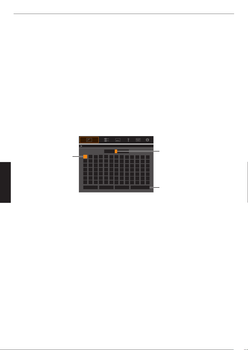
Contrast
For adjusting the white level point to avoid clipping or over saturation.
0
Setting range: -50 (little difference in brightness) to +50 (large difference in brightness)
Brightness
For adjusting the black level point to avoid clipping or over saturation.
0
Setting range: -50 (darker) to +50 (brighter)
Color
For adjusting the color saturation of the video image.
0
Setting range: -50 (lighter) to +50 (deeper)
Tint
For adjusting the hue of the video image.
0
Setting range: -50 (reddish) to +50 (greenish)
User Name Edit
You can edit the “User 1” to “User 6” names in the Picture mode.
0
Characters
that
are usable include alphabets (upper or lower case), numeric characters, symbols and blank (space)
character. (However, blank (space) cannot be used for the first and last characters.)
0
Enter not more than 10 characters.
User 1
}
?
.
y
l
Y
L
{
_
,
x
k
X
K
]
/
0
w
j
W
J
[
-
9
v
i
V
I
>
+
8
y
h
U
H
<
*
7
t
g
T
G
)
&
6
s
f
S
F
(
%
5
r
e
R
E
~
$
4
q
d
Q
D
|
#
3
p
c
P
C
;
"
2
o
b
O
B
\
^
z
M
Z
m
@
:
!
1
n
a
N
A
Name
After entry is complete, select
“OK” and press the [OK] button
Selection Cursor
Input Cursor
OKAll ClearClear
User Name Edit
Space
66
Adjust/Set
Color Profile
Configures the “Color Profile” (color space information) according to the preconfigured “Picture Mode”. It is also used
to fine-tune the preconfigured “Color Profile” settings.
Æ “Setting the Color Profile” (P. 41)
0
The available “Color Profile” settings vary according to “Picture Mode”.
Color Management, Color Selection, Hue, Saturation, Brightness
Each of the colors is adjustable according to the user’s preference.
Æ
“Adjusting to your Preferred Color (Color Management)” (P. 44
)
Color Temp.
Configures “Color Temp.” according to the preconfigured “Picture Mode”. It is also used to fine-tune the preconfigured
“Color Temp.” settings.
0
The “Color Temp.” settings available for configuration vary according to “Picture Mode”.
* When “Color Profile” is configured to “Off (Wide)/Off (Normal)” x y 5 6 or
“Off” z 4 7 8, the setting is fixed at “High Bright”.
“Color Temp.”
Color Temp. Description
Xenon 1 x y 5 6 Color temperature that reproduces the characteristics of a xenon lamp used in
cinemas.
0
Xenon 1: A light source color that is emitted by a film projector
0
Xenon 2: A light source color emitted by a projector used for digital cinema
Xenon 2 x y 5 6
5500K
Increasing the value enhances the blue tone of the video image, while decreasing
the value enhances the red tone.
6500K
7500K
9300K
High Bright Color temperature that gives priority to brightness.
HDR10+ Color temperature suitable for viewing HDR10+ content.
HDR10 Color temperature suitable for viewing HDR10 content. The default setting is
6500K.
HLG Color temperature suitable for viewing HLG content. The default setting is 6500K.
Custom 1 to Custom 2 The color temperature of video images can be adjusted manually and saved as
one of the three customized settings.
67
Adjust/Set
List of selectable “Color Temp.” according to “Picture Mode”
Picture Mode Color Temp.
Film x y 5 6 Xenon 1 x y 5 6
Xenon 2 x y 5 6
Custom 1 to Custom 2
Cinema 5500K
6500K
7500K
9300K
Xenon 1 x y 5 6
Xenon 2 x y 5 6
High Bright
Custom 1 to Custom 2
Natural
User 1 to User 3
5500K
6500K
7500K
9300K
High Bright
Custom 1 to Custom 2
HDR10+
HDR10+
*
Frame Adapt HDR
HDR10
Pana_PQ
5500K
6500K
7500K
9300K
High Bright
HDR10
Custom 1 to Custom 2
HLG 5500K
6500K
7500K
9300K
High Bright
HLG
Custom 1 to Custom 2
(Continue on next page)
68
Adjust/Set

Picture Mode Color Temp.
User 4 to User 6 5500K
6500K
7500K
9300K
High Bright
HDR10
HLG
Custom 1 to Custom 2
* When “Picture Mode” is set to “HDR10+”, the setting is fixed at “HDR10+”.
Correction Value
Configures the color temperature based on which “Gain Red” / “Gain Green” / “Gain Blue” / “Offset Red” / “Offset Green” /
“Offset Blue” are adjusted when “Color Temp.” is configured to “HDR10”“HLG”“Custom 1”“Custom 2”.
0
The “Correction Value” settings available for configuration vary according to “Picture Mode”.
Gain Red / Gain Green / Gain Blue
Adjusts each color in the bright parts of the video image.
0
Setting range: -255 (reduces the red/green/blue tone) to 0 (no adjustment)
Offset Red / Offset Green / Offset Blue
Adjusts each color in the dark areas of the video image.
0
Setting
range:
-50 (reduces the red/green/blue tone) to 0 (no adjustment) to +50 (enhances the red/green/blue tone)
List of selectable “Correction Value” according to “Picture Mode”
Picture Mode Correction Value
Film x y 5 6 Xenon 1 x y 5 6
Xenon 2 x y 5 6
Cinema 5500K
6500K
7500K
9300K
Xenon 1 x y 5 6
Xenon 2 x y 5 6
High Bright
Natural
Frame Adapt HDR
HDR10
Pana_PQ
HLG
User 1 to User 3
User 4 to User 6
5500K
6500K
7500K
9300K
High Bright
69
Adjust/Set
HDR Processing
This is
a feature for configuring the content analysis method using “Tone Mapping” when “Picture Mode” is configured
to “Frame Adapt HDR”.
*1 This item is not available when “Content Type” is set to “SDR”.
*2 When “Picture Mode” is configured to “HDR10+”, “HDR Processing” is fixed at “HDR10+”. “HDR10+” is used only
when the Picture Mode is configured to “HDR10+”.
*3 When “Picture Mode” is configured to “HDR10”“Pana_PQ”“HLG”“User 4 to User 6”, “HDR Processing” is fixed
at “Static”.
Setting Description
Frame by Frame Automatically adjusts the HDR tone mapping after analyzing the peak brightness
of each frame.
Scene by Scene Automatically adjusts the HDR tone mapping after analyzing the peak brightness
of each scene.
Static Configures based on the mastering information (MaxCLL/FALL) of the content and
does not make any dynamic adjustment.
HDR10+ Automatically adjusts the brightness for each scene based on the HDR10+ image
information.
*2
Gamma/Tone Mapping
This item adjusts “Gamma/Tone Mapping” according to the preconfigured “Picture Mode” (output value of the projected
video
with
respect to the video signal input). It is also used to adjust the preconfigured “Gamma/Tone Mapping” setting.
Æ “Adjusting the Output Value of the Projected Image (Gamma/Tone Mapping)” (P. 54)
0
The available “Gamma/Tone Mapping” settings vary according to the “Picture Mode”.
*1 When “Picture Mode” is set to “HDR10+”, the setting is fixed at “HDR(Auto)”.
*2 “Gamma/Tone Mapping” cannot be configured when “Picture Mode” is configured to “Frame Adapt HDR”.
Correction Value
For setting the base gamma for the adjustment of “Picture Tone”, “Dark Level” and “Bright Level” when one of the
“Custom 1” to “Custom 3” settings is selected in Gamma/Tone Mapping.
Æ
“Fine-tuning of Gamma/Tone Mapping to Preferred Settings” (P.
57
)
Color Selection
For selecting the color for adjusting “Picture Tone”, “Dark Level” and “Bright Level”.
Æ “Fine-tuning of Gamma/Tone Mapping to Preferred Settings” (P. 57)
Picture Tone
Adjusts the overall brightness automatically for a well-balanced result without compromising the gradation of the image.
Æ “Fine-tuning of Gamma/Tone Mapping to Preferred Settings” (P. 57)
Æ
“Performing Tone Mapping Manually” (P. 51)
Dark Level / Bright Level
You can adjust the image quality to produce a sharp contrast in the brightness.
Æ “Fine-tuning of Gamma/Tone Mapping to Preferred Settings” (P.
57
)
Æ “Performing Tone Mapping Manually” (P. 51)
70
Adjust/Set
Theater Optimizer
This feature
automatically configures the overall brightness level during tone mapping according to the screen size and
state of the projector.
Æ “Using the “Theater Optimizer”” (P. 48)
To use, configure the details of the screen in use in “Screen Setting”, followed by pressing “Set”.
*1 This option does not appear in the menu when “Content Type” is configured to “SDR”.
*2 This can be configured only when “Picture Mode” is configured to “Frame Adapt HDR”.
MEMO
Besides displaying the “Screen Setting” menu using “Installation”"“Screen Setting”, you can also press the “Screen
Setting” button in the “Theater Optimizer” menu to display it.
CAUTION
Pressing “Set”
in the “Theater Optimizer” menu automatically applies the details of the screen and state of the projector
in the auto settings of “Theater Optimizer”.
If “Set” is not pressed in the “Theater Optimizer” menu, the settings are applied after the next restart of the unit or change
of the “Installation Mode”.
HDR Level
This is a feature for adjusting the overall brightness during tone mapping. For configuring the auto correction intensity
of the “Theater Optimizer” feature when “Theater Optimizer” is configured to “On”.
*1 This option does not appear in the menu when “Content Type” is configured to “SDR”.
*2
This can be configured only when “Picture Mode” is configured to “Frame Adapt HDR” or “HDR10+”.
*3 The higher the nit level of the image the lower the HDR Level will be.
When “Picture Mode” is configured to “Frame Adapt HDR”, and “Theater Optimizer” is configured
to “Off”
Setting Description
Auto Automatically selects an appropriate tone mapping based on the mastering
information (MaxCLL/FALL) of the content.
-2 Displays in a tone map with 600 nits as the clip point.
-1 Displays in a tone map with 400 nits as the clip point.
0 Displays in a tone map with 300 nits as the clip point.
1 Displays in a tone map with 200 nits as the clip point.
2 Displays in a tone map with 150 nits as the clip point.
When “Picture Mode” is configured to “Frame Adapt HDR”, and “Theater Optimizer” is configured
to “On”
Setting Description
Auto Automatically corrects the overall brightness level based on the mastering
information (MaxCLL/FALL) of the content.
-2 to 2 For configuring the overall brightness level during auto correction.
-2 (dark) to 2 (bright)
71
Adjust/Set
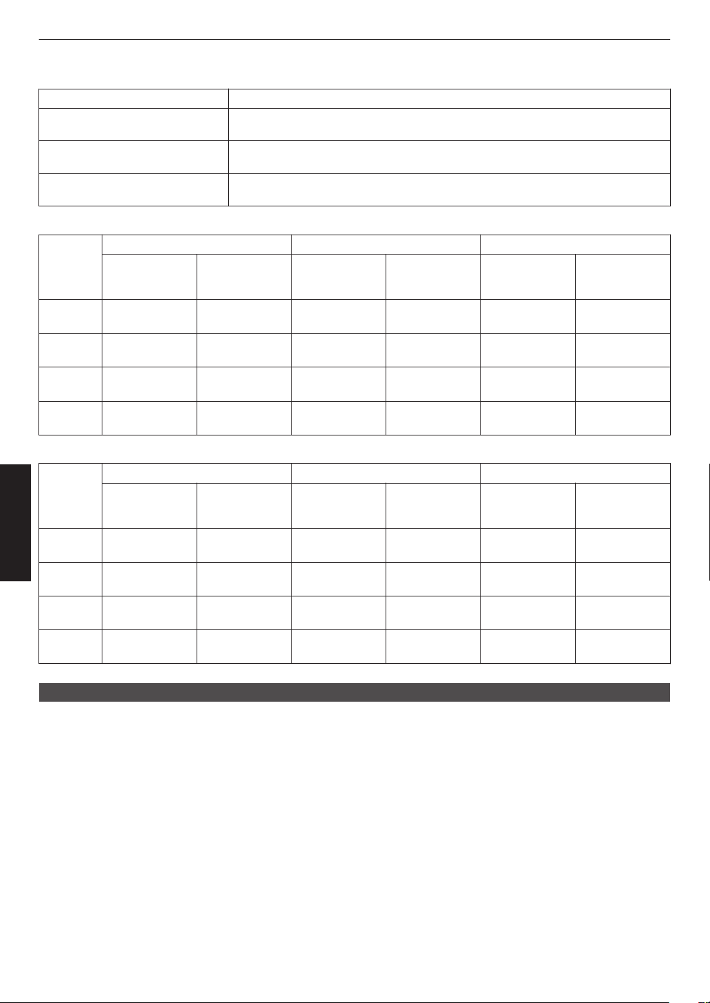
When “Picture Mode” is set to “HDR10+”
Setting Description
High
Displays the tone map when the overall brightness is configured to the high level.
This is suited for large-sized screens.
Mid
Displays the tone map when the overall brightness is configured to the medium
level. This is suited for medium-sized screens.
Low
Displays the tone map when the overall brightness is configured to the low level.
This is suited for small-sized screens.
To enjoy HDR10+ content when the Picture Mode is “HDR10+”, the following installation conditions are recommended.
HDR Level: High HDR Level: Medium HDR Level: Low
Screen Size
Diagonal
(Model)
Projection
Distance
(m)
Screen Size
Diagonal
(Model)
Projection
Distance
(m)
Screen Size
Diagonal
(Model)
Projection
Distance
(m)
x
5
116 3.63 99 3.31 86 2.67
y
6
113 3.48 97 2.98 84 2.60
z
7
109 3.43 93 2.92 80 2.50
4
8
88 2.81 75 2.39 65 2.02
HDR Level: High HDR Level: Medium HDR Level: Low
Screen Size
Diagonal
(Model)
Projection
Distance
(inch)
Screen Size
Diagonal
(Model)
Projection
Distance
(inch)
Screen Size
Diagonal
(Model)
Projection
Distance
(inch)
x
5
116 143 99 130 86 105
y
6
113 137 97 117 84 102
z
7
109 135 93 115 80 98
4
8
88 111 75 94 65 80
Mapping Level
For configuring the base brightness during auto correction when Gamma/Tone Mapping is configured to “HDR(Auto)”.
0
The
auto
correction feature of “HDR(Auto)” is configured based on a 100" screen with a gain of 1.0 in total darkness.
0
Adjust it in the positive direction if there is insufficient brightness in the viewing environment, and in the negative
direction if it is too bright.
*1 This option does not appear in the menu when “Content Type” is configured to “SDR”.
*2
This option does not appear in the menu when “Picture Mode” is configured to “Frame Adapt HDR”/“HDR10+”.
*3
When “Picture Mode” is configured to “Pana_PQ”“HLG”, “Mapping Level” is fixed at “0”.
*4 When “Picture Mode” is configured to “HDR10”“User 4 to User 6”, this option is enabled only when “Correction
Value” is configured to “HDR(Auto)” with “Tone Mapping” configured to “HDR(Auto)” or “Custom 1 to Custom 3”.
In all other settings, “Mapping Level” is fixed at “0”.
0
Setting range: -5 to 5
72
Adjust/Set
MPC/e-shift x y z 5 6 7 MPC Level 4 8
This is
a feature for adjusting the sharpness of the displayed image. It employs an original algorithm to create a natural
impression that is sharper at areas in focus and softer at areas that are not in focus, enabling you to enjoy highly
expressive images with a greater sense of depth.
8K e-shift x y z 5 6 7
For switching the e-shift display.
Setting Description
On Enables e-shift for display in 8K resolution
Off Disables e-shift and displays in 4K resolution
Graphic Mode
Switches the MPC setting.
It is recommended that this item be configured to “Standard” such as when viewing normal Blu-ray content, and to
“High-res 1” such as when viewing 8K/4K resolution content, and to “High-res 2” such as when inputting PC signals.
Setting Description
Standard
Performs enhancement processing suited for signal input with a resolution of 2K
or lower
High-res 1
Performs enhancement processing suited for signal input with a resolution of
8K/4K
High-res 2 Performs less enhancement processing than “High-res 1”.
Enhance
For adjusting the high-frequency areas. Increasing the value enhances the definition for a sharper image quality.
0
Setting range: 0 to 10
NR
For reducing the noise of the video image.
0
Setting range: 0 (weak) to 10 (strong)
BNR
For reducing the block noise of the video image.
0
Setting range: 0 (weak) to 3 (strong)
MNR
For reducing the mosquito noise of the video image.
0
Setting range: 0 (weak) to 3 (strong)
Toggling between the States before and during Adjustment
Pressing the [HIDE] button on the remote control enables you to toggle between the states before adjustment and
during adjustment.
Motion Control
For reducing the after-image, which occurs in a fast-moving scene.
Low Latency
Clear Motion Drive
Motion Enhance
Æ “Reducing the Delay and After-image of Fast-moving Images (Motion Control)” (P.
59
)
73
Adjust/Set
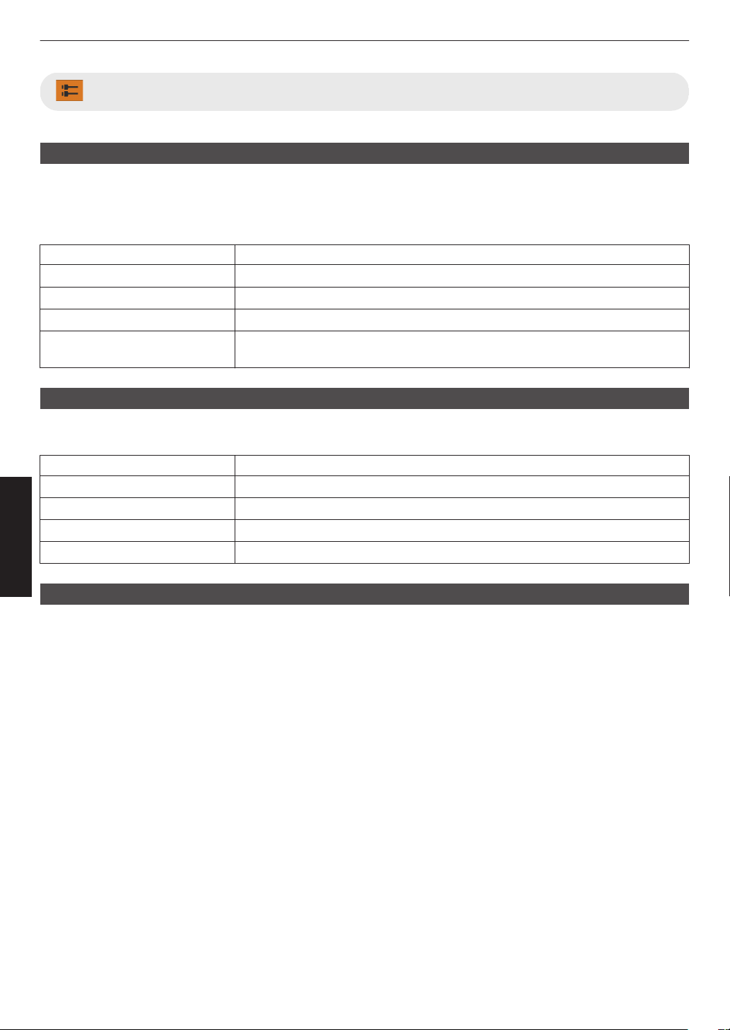
Input Signal
Input Level
For setting the dynamic range (gradation) of the video input.
If the image is not displayed properly even after selecting “Auto”, select an appropriate setting.
0
If the dynamic range is not appropriate, the bright areas become overexposed, and the dark areas become
underexposed.
Setting Description
Auto Sets the input signal level automatically.
16-235 (Video) Select this setting if you are inputting video signals (dynamic range: 16 - 235).
0-255 (PC) Select this setting if you are inputting PC signals (dynamic range: 0 - 255).
16-255 (S.White) Select this setting when inputting Super White-compatible device signals (dynamic
range: 16 - 255).
Color Space
For setting the color space of the input signal.
If the image is not displayed properly even after selecting “Auto”, select an appropriate setting.
Setting Description
Auto Detects “YCbCr444”, “YCbCr422”, and “RGB” automatically.
YCbCr444 Select this setting when inputting YCbCr (4:4:4) video signals.
YCbCr422 Select this setting when inputting YCbCr (4:2:2) video signals.
RGB Select this setting when inputting RGB video signals.
3D Setting
For setting 3D movies for viewing.
Æ “Viewing 3D Movies” (P. 37)
74
Adjust/Set
Auto Pic.Mode Select
For configuring
“Picture Mode” when the video type switches automatically while “Content Type” is configured to “Auto”.
SDR(2D)/SDR(3D)
For configuring the “Picture Mode” to switch to automatically during input of SDR (2D) or SDR (3D) signal.
Setting Description
Last Setting Switches to the “Picture Mode” that was last configured when viewing SDR (2D)
or SDR (3D) content.
Natural Switches the “Picture Mode” automatically to “Natural”.
Cinema Switches the “Picture Mode” automatically to “Cinema”.
Film x y 5 6 Switches the “Picture Mode” automatically to “Film”.
User 1 to User 3 Switches the “Picture Mode” automatically to “User 1” to “User 3”.
HDR10
For configuring the “Picture Mode” to switch to automatically during input of HDR10 signal.
Setting Description
Last Setting Switches to the “Picture Mode” that was last configured when viewing HDR10
content.
Frame Adapt HDR Switches the “Picture Mode” automatically to “Frame Adapt HDR”.
HDR10 Switches the “Picture Mode” automatically to “HDR10”.
Pana_PQ Switches the “Picture Mode” automatically to “Pana_PQ”.
User 4 to User 6 Switches the “Picture Mode” automatically to “User 4” to “User 6”.
HLG
For configuring the “Picture Mode” to switch to automatically during input of HLG signal.
Setting Description
Last Setting Switches to the “Picture Mode” that was last configured when viewing HLG content.
HLG Switches the “Picture Mode” automatically to “HLG”.
User 4 to User 6 Switches the “Picture Mode” automatically to “User 4” to “User 6”.
MEMO
0
The
“Auto
Pic.Mode Select” settings are saved separately for each input terminal. The name of the currently selected
input terminal is shown at the top right corner of the “Auto Pic.Mode Select” menu.
0
To switch
to configure the settings for a different input terminal, press the “INPUT” button on the remote control unit,
or press the ↑↓ key on the projector unit after turning off the menu screen.
75
Adjust/Set
HDMI EDID Setting
Mode
For changing the EDID mode of the “HDMI 1/HDMI 2” terminal. Set to “A” under normal condition. The images may not
be displayed on some old devices. In this case, try “B” or “C”.
Setting Description
A
Configures the EDID mode to “A”
Supports up to 8K60p x y z 5 6 7 and 4K120p.
B
Configures the EDID mode to “B”
Supports up to 4K60p.
C
Configures the EDID mode to “C”
Supports up to 1080p60.
* EDID (Extended Display Identification Data) refers to the information, such as supported resolutions, exchanged
between devices.
DSC
For configuring whether DSC transmission is allowed. Set to “On” under normal condition.
Setting Description
On Allows compressed video transmission
Off Prohibits compressed video transmission
* DSC (Display Stream Compression) is one of the lossy video signal compression transmission technologies.
HDR10+
For configuring whether HDR10+ transmission is allowed. To enjoy HDR10+ content, configure to “On”.
Setting Description
On Allows HDR10+ transmission
Off Prohibits HDR10+ transmission
MEMO
0
The “HDMI
EDID Setting” settings are saved separately for each input terminal. The name of the currently selected
input terminal is shown at the top right corner of the “HDMI EDID Setting” menu.
0
To switch
to configure the settings for a different input terminal, press the “INPUT” button on the remote control unit,
or press the ↑↓ key on the projector unit after turning off the menu screen.
76
Adjust/Set
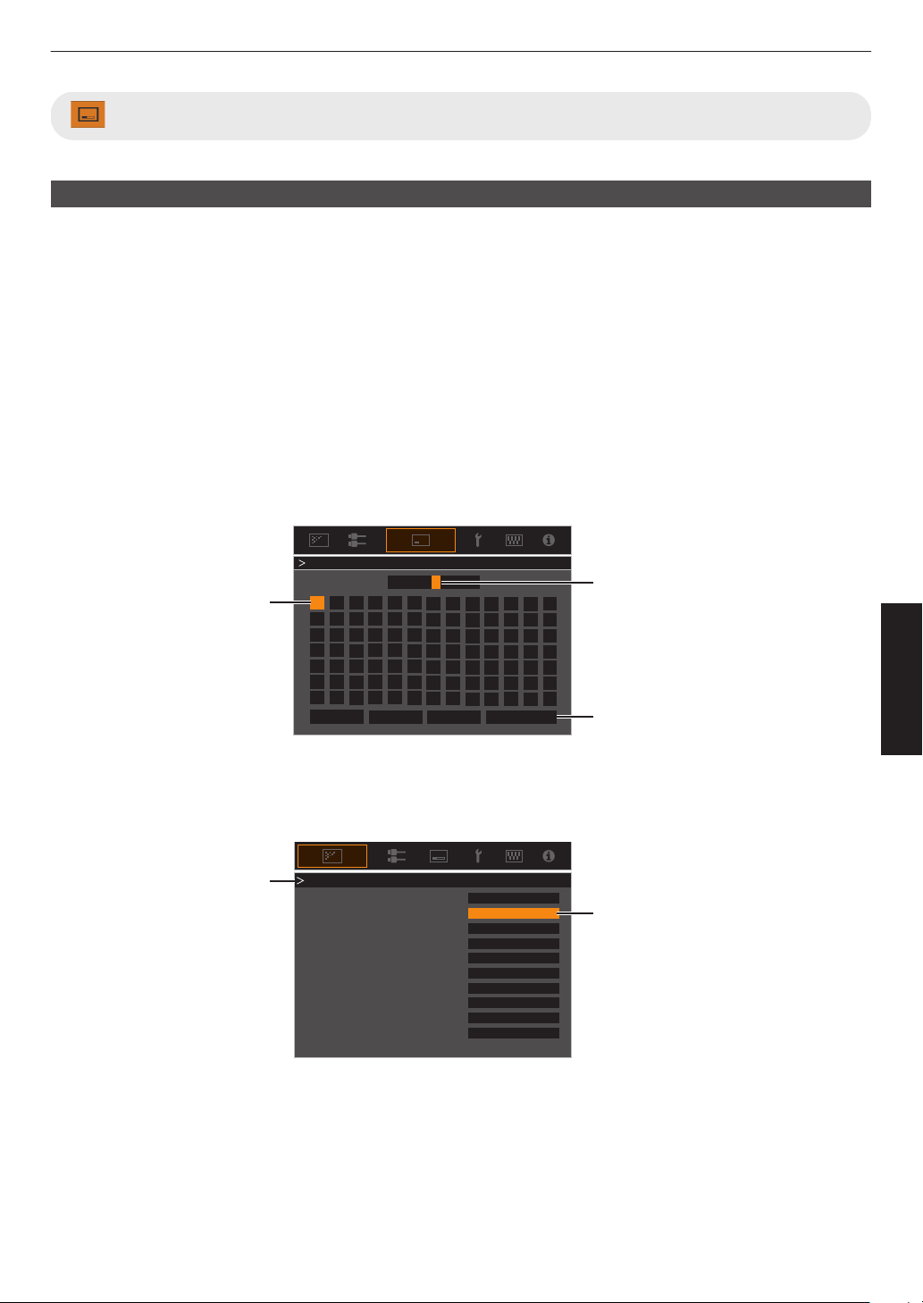
Installation
Installation Mode
Collectively manages the setting values of “Lens Control”, “Pixel Adjust”, “Mask”, “Anamorphic”, “Screen Setting”,
“Installation Style”, “Keystone” and “Aspect”.
* The lens position may be shifted slightly with respect to the position that was saved.
Mode Select
For selecting the group to save and retrieve the setting values.
0
Setting values: Mode 1 to Mode 10
* The name of the setting value can be changed using “Name Edit”.
Name Edit
For editing the name of Installation Mode.
0
Characters
that
are usable include alphabets (upper or lower case), numeric characters, symbols and blank (space)
character. (However, blank (space) cannot be used for the first and last characters.)
0
Enter not more than 10 characters.
}
?
.
y
l
Y
L
{
_
,
x
k
X
K
]
/
0
w
j
W
J
[
-
9
v
i
V
I
>
+
8
y
h
U
H
<
*
7
t
g
T
G
)
&
6
s
f
S
F
(
%
5
r
e
R
E
~
$
4
q
d
Q
D
|
#
3
p
c
P
C
;
"
2
o
b
O
B
\
^
z
M
Z
m
@
:
!
1
n
a
N
A
Name Mode 1
After entry is complete, select
“OK” and press the [OK] button
Selection Cursor
Input Cursor
OKAll ClearClear
Space
Name Edit
Mode Copy
For copying the setting values managed by the current Installation Mode to another mode.
Copy 16:9
16:9
16:9
Select the mode to copy to and
press the [OK] button.
Current Mode
Set
Set
Set
Set
Set
Set
Set
Set
Set
SetMode 10
Mode 9
Mode 8
Mode 7
Mode 6
Mode 5
Mode 4
Mode 3
77
Adjust/Set
Lens Control
Focus / Zoom / Shift
For adjusting the lens according to the projection position
Æ “Adjusting the Lens According to the Projection Position” (P. 35
)
Image Pattern
For setting whether to display the lens adjustment pattern.
Setting Description
Off Displays external signals, and does not display the lens adjustment pattern.
On Displays the lens adjustment pattern.
Lock
For setting whether to lock or unlock the lens.
Setting to “On” to lock the lens allows you to preserve the adjustment status of the lens.
Setting Description
Off Does not lock the lens.
On Locks the lens to prevent any erroneous operation on the adjustments.
0
Even when “On”, the lens will be in the mode selected by “Installation Mode”.
Lens Center
Returns the lens position to the center.
78
Adjust/Set
Pixel Adjust
For correcting the phase shifting between each RGB color by adjusting the pixel.
Adjust
For setting the adjustment feature to On or Off.
Adjust Area
Setting Description
Whole Adjusts the entire image.
Zone Enables fine adjustment of each area by dividing the screen evenly into 10 vertical
and horizontal zones.
Adjust Color
For selecting the color to adjust (“Red” or “Blue”).
Adjust Pattern
Setting Description
Off Displays the external signals without displaying the test pattern for adjustment.
On Displays the test pattern for adjustment.
Adjust Pattern Color
For setting the color of the adjustment pattern displayed during adjustment to “White” or “Yellow / Cyan”.
Adjust (Pixel)
When “Adjust Area” is set to “Whole”, adjustment can be made by moving in units of one pixel on the screen of the color
selected in “Adjust Color”.
Æ “Whole Adjust (Pixel) Operation Procedure” (P.
80)
0
Adjustment cannot be made when “Adjust Area” is set to “Zone”.
Setting Description
H (Horizontal) Setting range: -2 (moves red/blue to the left) to +2 (moves red/blue to the right)
V (Vertical) Setting range: -2 (moves red/blue downward) to +2 (moves red/blue upward)
Adjust (Fine)
When “Adjust Area” is set to “Whole”, adjustment can be made by moving in units of 1/8 pixel on the screen of the color
selected in “Adjust Color”.
Æ “Whole Adjust (Fine) Operation Procedure” (P. 81)
When “Adjust Area” is set to “Zone”, the screen is divided evenly into 10 vertical and horizontal zones, and fine
adjustment of each area is possible.
Æ “Zone Adjust Operation Procedure” (P. 82)
Setting Description
H (Horizontal) Setting range: -31 (moves red/blue to the left) to +31 (moves red/blue to the right)
V (Vertical) Setting range: -31 (moves red/blue downward) to +31 (moves red/blue upward)
Reset
Restores all pixel adjustment data to the factory default.
79
Adjust/Set
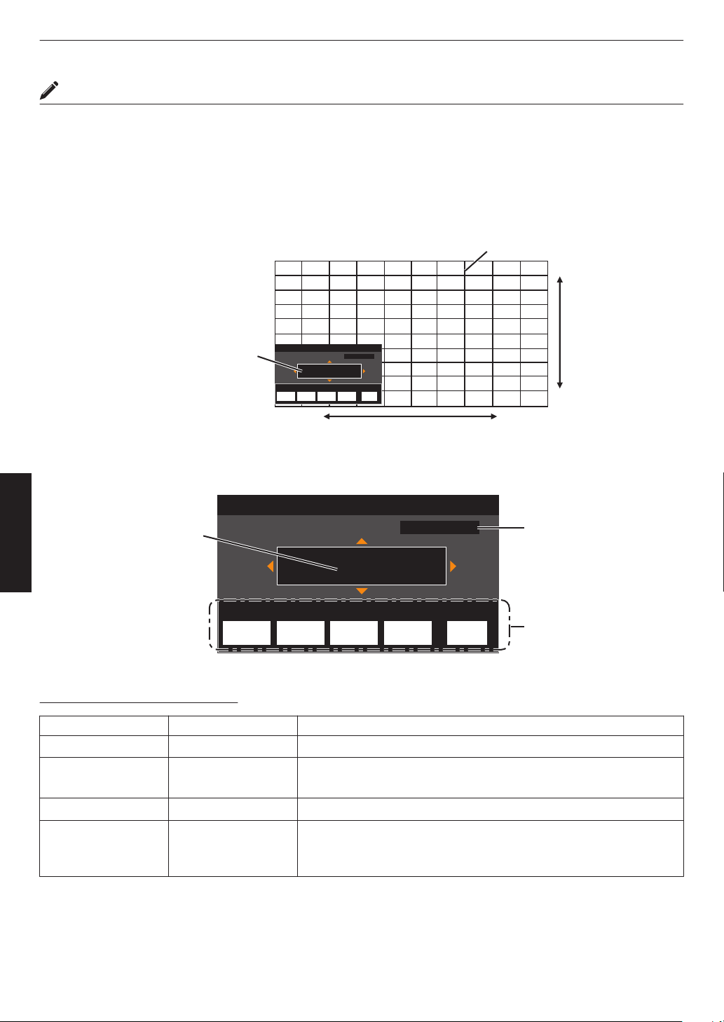
Whole Adjust (Pixel) Operation Procedure
For making general adjustments to slight color fringing in the horizontal/vertical directions of the video image.
A
Set “Adjust Area” to “Whole”
B
Select “Adjust Color” and “Adjust Pattern Color”
C
Select “Adjust (Pixel)”, and press the [OK] button
0
The Adjustment mode is activated, and the selected adjustment pattern and Adjustment (Pixel) window are
displayed.
Adj.AreaPat.Col.Pixel/FineAdj.Col.
H 0
V 0
Red
Pixel Adjust
Back
Whole Adjust (Pixel)
BACK
ADVANCED
MENU
GAMMA
SETTINGS
C.M.D.
PICTURE
MODE
V (Vertical)
H (Horizontal)
Adjustment (Pixel) Window
Adjustment Pattern
D
Use the [JKH I] keys to move and adjust the vertical and horizontal pixels of the entire zone
0
The adjustment setting appears at the center of the Adjustment (Pixel) window.
Adj.AreaPat.Col.Pixel/FineAdj.Col.
H 0
V 0
Red
Pixel Adjust
Back
Whole Adjust (Pixel)
BACK
ADVANCED
MENU
GAMMA
SETTINGS
C.M.D.
PICTURE
MODE
Remote Control
Operation Guide
Color for
Adjustment
Pixel Adjustment Setting
E
After adjustment is complete, press the [BACK] button twice to exit the Adjustment mode
Remote Control Operation Guide
Button Name Function Description of Operation
[PICTURE MODE] Adj.Col. Changes “Adjust Color”.
[C.M.D.] Pixel/Fine Switches between “Adjust (Pixel)” and “Adjust (Fine)”.
0
Switches to “Adjust (Pixel)” when “Adjust Area” is set to “Zone”.
[GAMMA SETTINGS] Pat.Col. Changes “Adjust Pattern Color”.
[ADVANCED MENU] Adj.Area Switches “Adjust Area”.
0
A zone cursor appears on the adjustment pattern when the “Zone”
setting is selected.
80
Adjust/Set
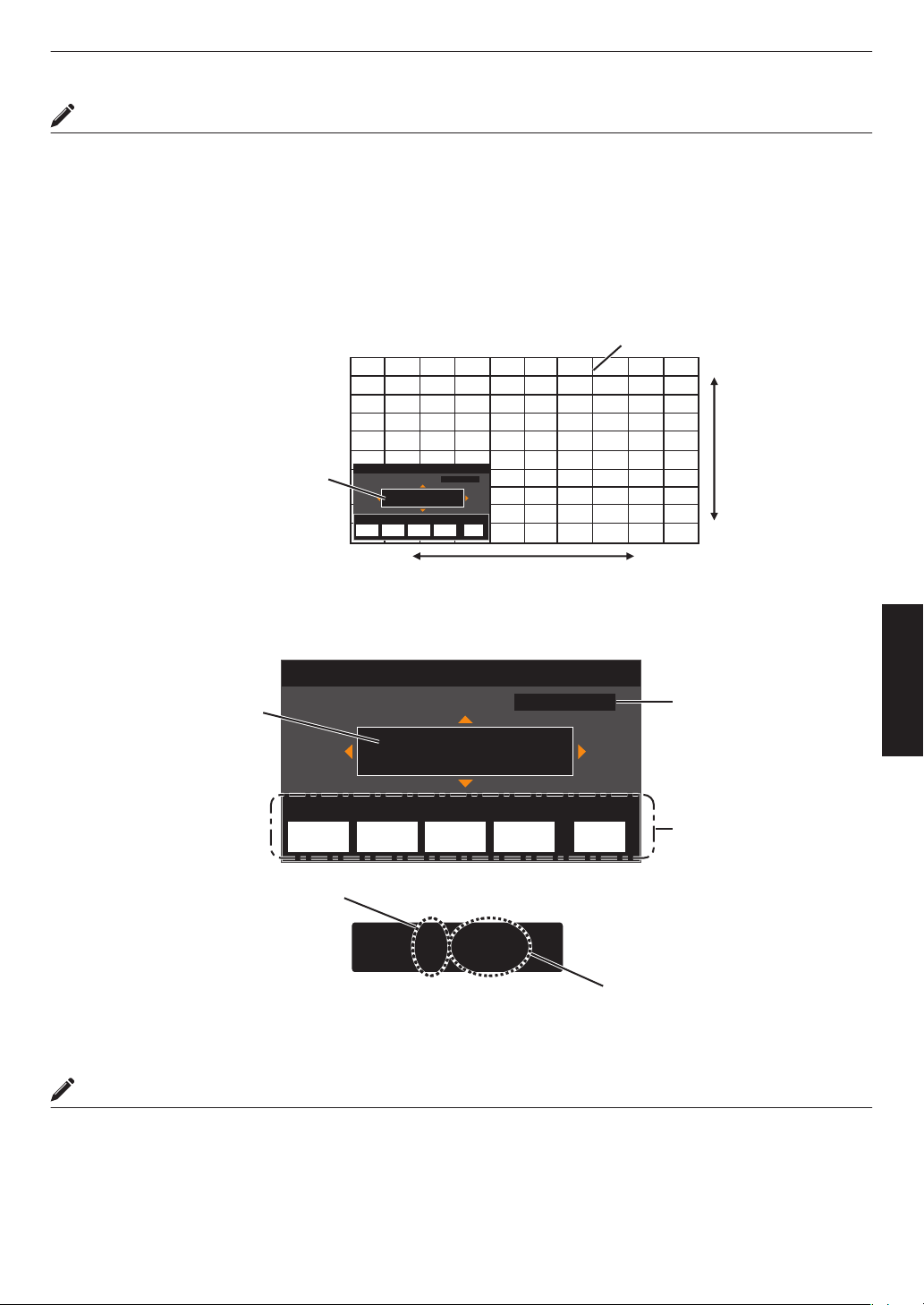
Whole Adjust (Fine) Operation Procedure
For making general adjustments on the misalignment of the entire screen using “Adjust (Pixel)”, followed by making
fine adjustments.
A
Set “Adjust Area” to “Whole”
B
Select “Adjust Color” and “Adjust Pattern Color”
C
Select Adjust (Fine), and press the [OK] button
0
The Adjustment mode is activated, and the selected adjustment pattern and Fine window are displayed.
0
The adjustable range may be smaller depending on the pixels being adjusted on the entire screen.
Adj.AreaPat.Col.Pixel/FineAdj.Col.
H 0( 0/ 0)
V 0( 0/ 0)
BACK
ADVANCED
MENU
GAMMA
SETTINGS
C.M.D.
PICTURE
MODE
Red
Whole Adjust (Fine)
Pixel Adjust
Back
V (Vertical)
H (Horizontal)
Fine Window
Adjustment Pattern
D
Use the [JKH I] keys to move and adjust the vertical and horizontal pixels of the entire zone
0
The adjustment setting appears at the center of the Fine window.
Adj.AreaPat.Col.Pixel/FineAdj.Col.
H 0( 0/ 0)
V 0( 0/ 0)
BACK
ADVANCED
MENU
GAMMA
SETTINGS
C.M.D.
PICTURE
MODE
H -20(-20 / -20)
V 5 ( 5 / 5)
Red
Whole Adjust (Fine)
Pixel Adjust
Back
Indicates the maximum and
minimum misalignment value of
the entire screen.(Max. / Min.)
Adjustment Setting
Remote Control
Operation Guide
Color for
Adjustment
Pixel Adjustment Setting
E
After adjustment is complete, press the [BACK] button twice to exit the Adjustment mode
MEMO
0
If both the maximum overall screen misalignment of H (horizontal direction) and V (vertical direction) are “31”, you
cannot select a value that is larger than the displayed setting even when the adjustment setting is lower than the
maximum value.
0
If the minimum overall screen misalignment is “-31”, you cannot select a value that is smaller than the displayed
setting even when the adjustment setting is higher than the minimum value.
81
Adjust/Set
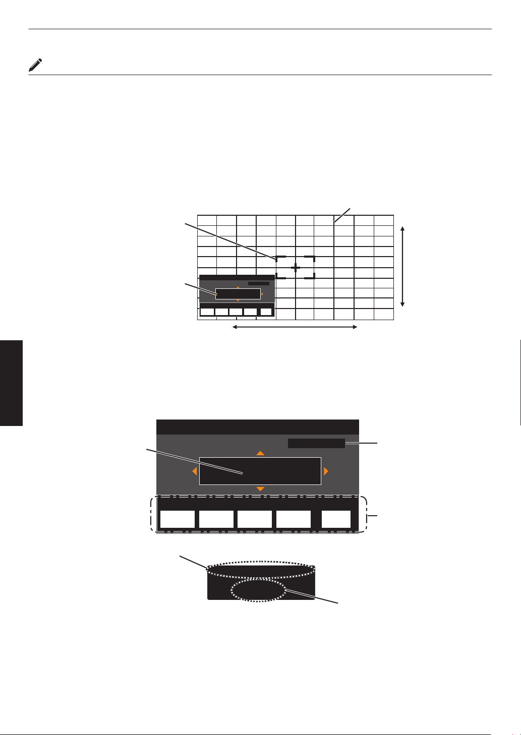
Zone Adjust Operation Procedure
For fine-tuning misalignments on a part of the screen after adjusting the overall screen misalignment using “Adjust
(Pixel)” and “Adjust (Fine)”.
0
The screen can be divided vertically and horizontally into 10 sections for partial adjustments to be made.
A
Set “Adjust Area” to “Zone”
B
Select “Adjust Color” and “Adjust Pattern Color”
C
Select Adjust (Fine), and press the [OK] button
0
The
Adjustment
mode is activated, and the selected adjustment pattern and Zone Adjustment window are displayed.
0
The adjustable range may be smaller depending on the pixels being adjusted on the entire screen.
Adj.AreaPat.Col.Pixel/FineAdj.Col.
H 0
V 0
BACK
ADVANCED
MENU
GAMMA
SETTINGS
C.M.D.
PICTURE
MODE
Red
Back
0 / 0
Position
Zone Adjust
Pixel Adjust
V (Vertical)
H (Horizontal)
Zone Adjustment Window
Zone Cursor
Adjustment Pattern
D
Press the [JKH I] keys to move the cursor to the point to be adjusted
E
Press the [OK] button to enter the Adjustment mode
F
Use the [JKH I] keys to move and adjust the vertical and horizontal pixels of the entire zone
0
The adjustment setting appears at the center of the Zone Adjustment window.
Adj.AreaPat.Col.Pixel/FineAdj.Col.
H 0
V 0
BACK
ADVANCED
MENU
GAMMA
SETTINGS
C.M.D.
PICTURE
MODE
Red
Back
-31
7
H
V
0 / 0
8 / 5
Position
Zone Adjust
Pixel Adjust
Position
Adjustment Setting
Cursor Position
Remote Control
Operation Guide
Color for
Adjustment
Pixel Adjustment Setting
G
After adjustment is complete, press the [BACK] button twice to exit the Adjustment mode
82
Adjust/Set
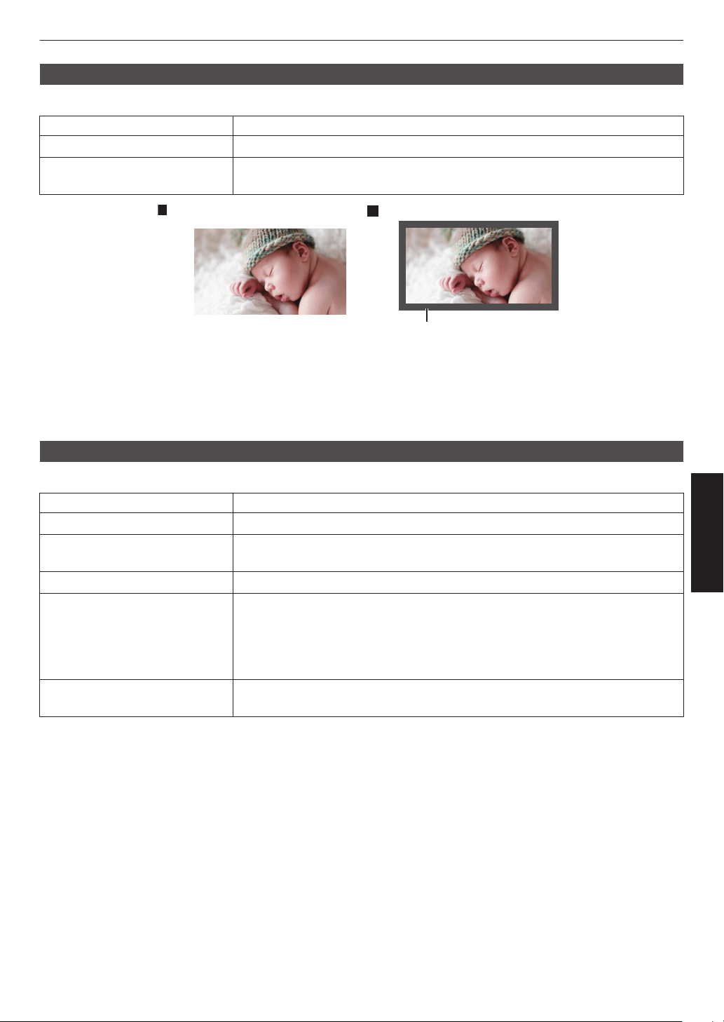
Mask
For hiding the peripheral area of the image with a mask (black strip).
Setting Description
Off Not masked.
On Hides the ranges specified in “Top”, “Bottom”, “Left” and “Right” by masking (with
black strips).
Mask: black strip around the
p
eri
p
her
y
On
Off
“Top” / “Bottom” / “Left” / “Right”
For specifying the ranges to hide by masking (with black strips).
0
Setting range: 0 to 220
Anamorphic
Configure this setting when an anamorphic lens is used.
Setting Description
Off Projects the 2.35:1 image without any changes.
A Projects the 2.35:1 image with it stretched in the vertical direction only using a 3840
pixel width.
B Projects the 16:9 image with it compressed in the horizontal direction only.
C This is a mode used exclusively for the DCR lens of Panamorph.
Projects the image by stretching 2.35:1 video images in the vertical direction and
enlarging them in the horizontal direction to the maximum panel width of 4096
pixels.
This is configured to “A” in the 3D mode.
D This is a mode used exclusively for the DCR lens of Panamorph.
Projects the 16:9 image with it compressed in the horizontal direction only.
83
Adjust/Set
Screen Setting
Screen Adjust
Corrects the color temperature according to the properties of the screen to be used.
Selecting the
optimal correction mode enables corrections to be performed to reproduce natural images with balanced
colors.
0
This
feature
is not available when “Color Profile” is configured to “Off (Wide)”“Off (Normal)” x y 5 6
or “Off” z 4 7 8.
Setting Description
Off Does not perform correction
On Corrects the color temperature according to the properties of the screen configured
in “Screen No.”.
Screen No.
For configuring the correction mode according to the screen to be used.
0
This item cannot be set when “Screen Adjust” is set to “Off”.
0
For information on the screen and the corresponding correction mode, please visit our website.
https://www.jvc.com/global/projector/screen
MEMO
0
You can utilize the optional optical sensor and dedicated projector calibration software to make finer adjustments.
For details on the dedicated projector calibration software, please visit our website.
http://www3.jvckenwood.com/english/download/
Screen Size(Diagonal)
For configuring the size (diagonal) of the screen for viewing when using the “Theater Optimizer” function.
Screen Aspect
For configuring the aspect ratio of the screen for viewing when using the “Theater Optimizer” function.
Screen Gain
For configuring the gain of the screen for viewing when using “Theater Optimizer”.
MEMO
0
Configuring “Theater Optimizer” to “On” enables the brightness level during “Tone Mapping” to be adjusted
automatically according to the screen size and state of the projector when picture mode is configured to “Frame
Adapt HDR”.
0
The “Theater Optimizer” can be displayed by pressing “Theater Optimizer”.
(This option is disabled when picture mode is configured to a mode other than “Frame Adapt HDR”.)
Æ “Using the “Theater Optimizer”” (P. 48)
CAUTION
The “Screen Size”“Screen Gain” settings will be applied to the auto settings of “Theater Optimizer” during the next
restart of the unit or change of the “Installation Mode”.
To apply the settings immediately, press “Set” in the “Theater Optimizer” menu.
84
Adjust/Set
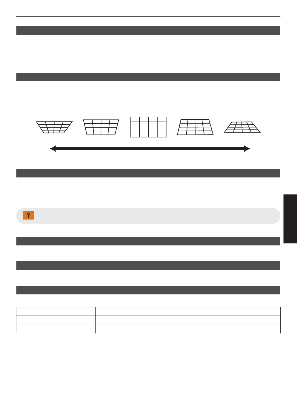
Installation Style
For setting to “Front”, “Ceiling Mount (F)”, “Rear”, or “Ceiling Mount (R)” according to the installation status of the
projector.
0
“Front” or “Ceiling Mount (F)” is set when projector is installed in the front with respect to the screen.
0
“Rear” or “Ceiling Mount (R)” is set when projector is installed in the rear with respect to the screen.
Keystone
For correcting any keystone distortion that occurs when the projector is installed at an angle with respect to the screen.
0
Vertical setting range: -7 to 7
* Increasing the value changes the aspect slightly.
* Image will reduce in size when keystone is adjusted.
-7
0
7
Aspect
The screen size of the projected image can be adjusted optimally according to the original screen size (aspect) that
has been input.
Æ “Adjusting the Screen Size (Aspect)” (P. 36)
Display Setup
Back Color
For setting the color of the background to “Blue” or “Black” when there is no signal input.
Menu Position
For setting the display position of the menu.
Signal Display
For setting the display of the input information to “On” or “Off”.
Setting Description
Off Not displayed.
On Shows the input terminal for 5 seconds when input is switched.
85
Adjust/Set
Logo
For setting the display of logo during startup to “On” or “Off”.
Setting Description
Off Not displayed.
On Displays the “D-ILA” logo for 5 seconds during startup.
Language
For setting the display language to “English”, “Deutsch”, “Español”, “Italiano”, “Français”, “Português”, “Nederlands”,
“Polski”, “Norsk”, “Русский”, “
繁體中文”, or “日本語”.
Function
Trigger
For setting whether to supply a 12 V output to devices such as an external screen equipped with a trigger function.
Setting Description
Off No output.
Power Outputs control signals (12 V) from the trigger terminal when the power is turned
on.
Anamo Outputs control signals when the “Anamorphic” setting is changed from “Off” to a
setting other than “Off”. Outputs control signals when the projector is powered on
if “Anamorphic”
is configured to a setting other than “Off” when the power is turned
on.
Inst. Mode 1 to Inst. Mode 10 Outputs control signals when the “Installation Mode” number to be retrieved is the
same as the number configured. Outputs control signals when the projector is
powered on if the “Installation mode” has the same number as this setting when
the power is turned on.
* When a setting other than “Off” is selected, the control signal output is stopped when the cooling function starts once
the power is turned off.
Off Timer
For setting the duration before the power turns off automatically when the projector is not operated.
0
Setting values: “Off”, “1 Hour”, “2 Hours”, “3 Hours” and “4 Hours”
* The setting will be retained even after the Off Timer operation has completed.
ECO Mode
Setting Description
On Enables “ECO Mode” to minimize power consumption in the Standby mode.
0
RS-232C / LAN communication cannot be used in the Standby mode.
0
If there is no signal transmission and operation for 15 minutes while an image
is
projected,
the power management switches the equipment automatically into
standby mode.
Off Select this option to control via RS-232C / LAN communication in the Standby
mode or if Control4 is to be used.
* If this unit enters into standby while “ECO Mode” is set to “On”, all the indicators on the unit including the “STANDBY/
ON” indicator are turned off. To turn on the power from this state, use the [STANDBY/ON] button on the unit.
Alternatively, press any button on the remote control once to cancel the standby mode then press the [ON] button
on the remote control.
86
Adjust/Set
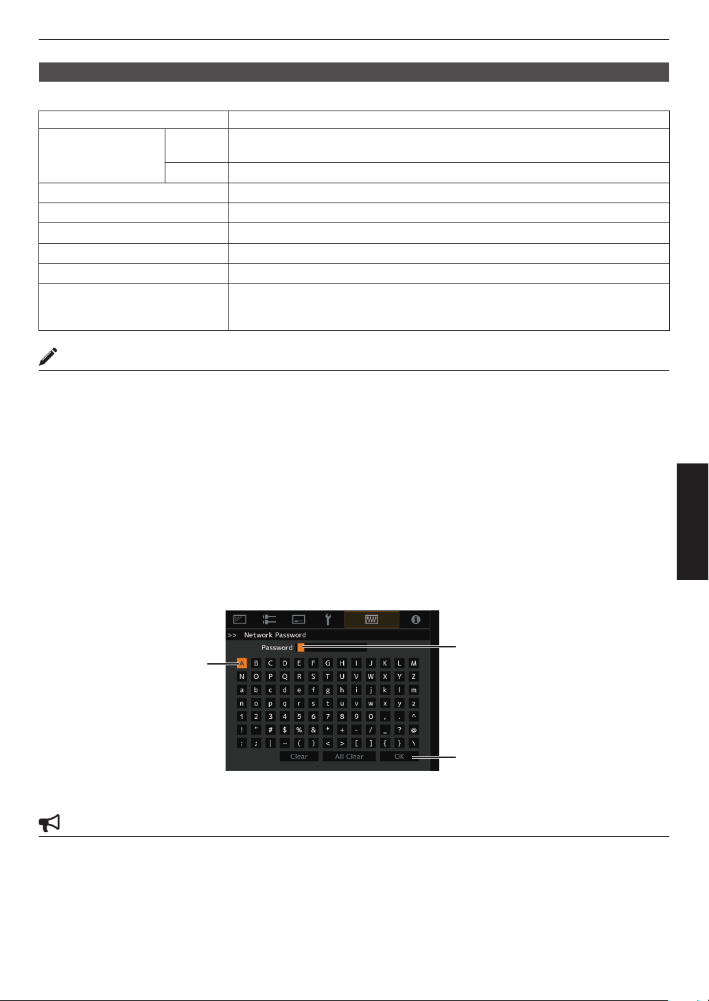
Network
For specifying the settings for external control from a PC or smartphone.
Setting Description
DHCP Client On Obtains the IP address automatically from the DHCP server inside the connected
network.
Off For configuring the network settings manually.
IP Address For configuring the IP address.
Subnet Mask For configuring the subnet mask.
Default Gateway For configuring the default gateway.
MAC Address Displays the MAC address of the unit.
Set Applies the network settings.
Control4 SDDP Set to “On” to allow Control4 SDDP to detect this unit.
When this
unit is not connected to an environment under the control of the controller
and Control4 SDDP from the Control4 Corporation, set this to “Off”.
Glossary of Network Terminology
DHCP :
Abbreviation for Dynamic Host Configuration Protocol. This is a protocol for the network
to assign an IP address automatically to the connected device.
IP Address : Numeric characters for identifying the device that is connected to the network.
Subnet Mask : Numeric characters that define the bit count used for the network address that is a
segment of the IP address.
Default Gateway : Server for communicating beyond the network that is divided by the subnet mask.
MAC Address : Abbreviation for Media Access Control address. This is a number that is unique to each
network adapter. Each of the network adapters is assigned with a unique MAC address.
Network Password
DLA-NZ9BK, DLA-NZ8BK, DLA-NZ7BK, DLA-NP5BK, DLA-RS4100K, DLA-RS3100K, DLA-RS2100K, DLA-
RS1100K only
For configuring the password during LAN connection.
0
Characters that are usable include alphabets (upper or lower case), numeric characters, and symbols.
0
Enter a password with at least 8 characters and not more than 10 characters.
After entry is complete, select
“OK” and press the [OK] button
Selection Cursor
Input Cursor
CAUTION
0
Configuration of a network password is necessary before connecting to the LAN terminal.
87
Adjust/Set
Remote Code
For changing the remote control code.
Setting Description
A Change the remote control code from “B” to “A”.
B Change the remote control code from “A” to “B”.
0
You need to configure the remote control according to the settings of this unit.
On the
remote control unit, press the [MENU] button for three seconds or longer while pressing and hold the [BACK]
button to switch the code.
0
The backlight of the remote control blinks 3 times: change the remote control code to “A”
0
The backlight of the remote control blinks 2 times: change the remote control code to “B”
0
If the setting differs between this unit and the remote control, the “STANDBY/ON” indicator blinks in green when
receiving the remote control code.
LIGHT
STANDBY/ON
WARNING
ANDBY/O
(Green)
88
Adjust/Set
High Altitude Mode
For setting the high altitude mode to “On” or “Off”.
Set to
“On” when using the projector at a location of low atmospheric pressure (higher than 900 m (3,000 ft) above sea
level).
Hide Mode x y z 5 6 7
For reducing the power consumption through suppressing the current supply for the LD block when the [HIDE] button
is pressed to hide the image temporarily.
Setting Description
Off
The illumination supply remains on when the [HIDE] button is pressed to hide the
image.
On
The illumination supply is turned off when the [HIDE] button is pressed to hide the
image.
Lamp Reset 4 8
Resets the lamp time.
Æ “Resetting the Lamp Time 4 8” (P.
93)
Factory Reset
For restoring the settings of this unit to the factory default. However, the following settings will not be reset.
0
Gamma data saved in “Gamma” " “Correction Value” " “Import”.
0
Color profile data saved in “Color Profile” " “Custom1 to Custom6”.
Software Update
For performing a software update.
For the latest information on the software, refer to https://www3.jvckenwood.com/english/download/.
License
For displaying the license in use.
89
Adjust/Set
Information
Setting Description
Input Displays the currently selected video input terminal.
Source
(Displayed only during video signal input)
Displays the input source.
Resolution
(Displayed only during PC signal input)
Displays the image resolution.
H Frequency
Displays the horizontal frequency.
V Frequency
Displays the vertical frequency.
Color Space Displays the color space and color bit depth of the input video signal.
0
The color bit depth is not displayed when “YCbCr422” is input.
0
The color bit depth is displayed when color bit depth information is received
from the source device.
Colorimetry Displays the Colorimetry of the input signal.
HDR Displays the EOTF information when HDR packet is received. Displays “HDR10+”
when HDR10+ packets are received.
Max CLL/Max FALL Displays the mastering information of the content during HDR playback.
Max CLL: Maximum Content Light Level
Max FALL: Maximum Frame Average Light Level
0
The information may not be displayed depending on the player and content.
Light Source Time
x y z 5 6
7
Displays the laser light source time.
Lamp Time 4 8 Displays the number of lamp hours used.
Soft Ver. Displays the firmware version.
90
Adjust/Set
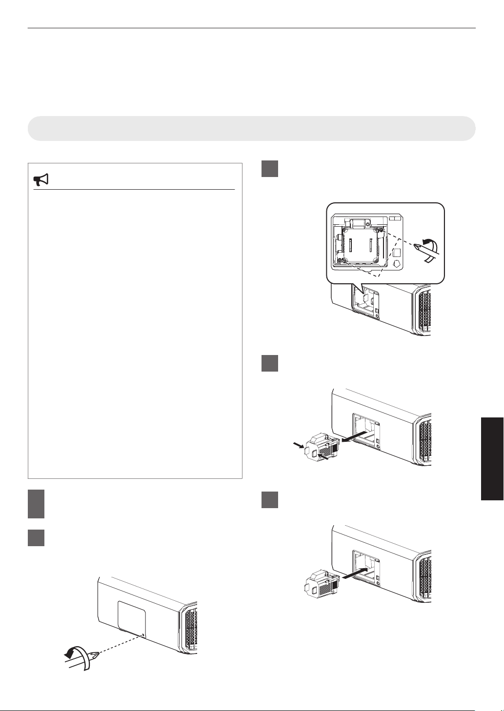
Replacing the Lamp 4 8
The lamp is a consumable item. If the image appears dark or the lamp goes out, replace the lamp unit.
0
When the lamp replacement time approaches, the user is notified with a message displayed on the screen and by
the indicator. (P. 114)
Lamp Replacement Procedure
CAUTION
0
Do not insert your hands into the lamp
compartment. This could cause significant
deterioration in the performance of the
equipment, or lead to injury and electric shock.
0
Do
not
replace the lamp immediately after the unit
has been used. Allow a cooling period of at least
one hour before replacement. The temperature of
the lamp is still high, and may cause burn injuries.
0
Do not subject the lamp unit to shock. Doing so
may cause lamp blowout.
0
Do not use a flammable air duster to clean the
internal
parts
of the unit. Doing so may cause fire.
0
Use only
genuine replacement parts for the lamp
unit. Also, never attempt to reuse an old lamp unit.
Doing so may shorten the lamp life and cause a
malfunction.
0
Do not
touch the surface of a new lamp. Doing so
may shorten the lamp life and cause lamp
blowout.
0
When replacing
the lamp, be careful not to injure
yourself as the lamp may be broken.
0
When replacing the lamp of a projector
suspended from the ceiling, work at height is
required. This is a dangerous operation. Please
consult our service center.
1
Remove the power plug from the
outlet
2
Remove the lamp cover
0
Remove the screw with a t screwdriver
3
Loosen the screws of the lamp unit
0
Loosen the screws with a t screwdriver.
4
Pull out the lamp unit
5
Install the new lamp unit
91
Maintenance
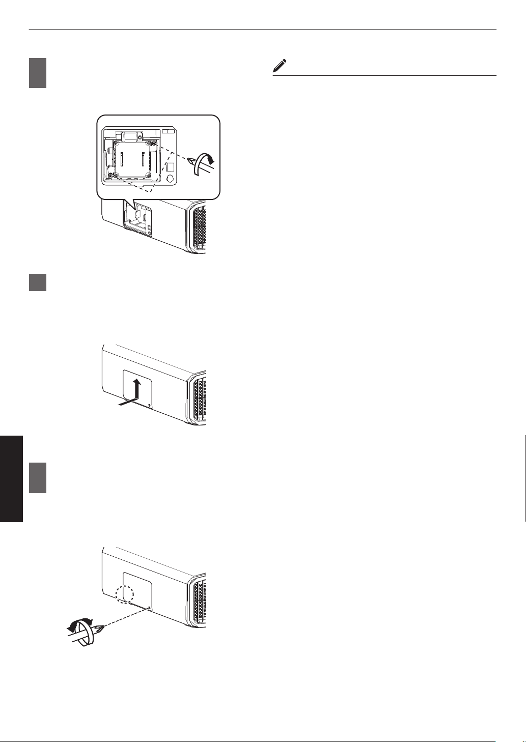
6
Tighten the screws of the new lamp
unit
0
Tighten the screws with a t screwdriver.
7
Attach the lamp cover
0
Slide
the
lamp cover from below and ensure that
the two tabs at the top of the cover are inserted
into the projector unit.
8
Tighten the screw with a t
screwdriver
0
After ensuring that the corner indicated by the
circle is properly seated, tighten the screw with
a t screwdriver.
MEMO
Usable lamp life
0
When the lamp is used with “Lamp Power” set to
“Low”,
the
lamp life on this unit is approximately 4500
hours. This is the average usable time and not a
guaranteed value.
0
The lamp
life may not reach 4500 hours depending on
the operating conditions.
0
When the
lamp has reached the end of its usable life,
deterioration progresses rapidly.
0
When the video image appears dark, when the color
tone looks unnatural, or when the image flickers,
replace the lamp unit with a new one promptly.
Purchasing a lamp unit
For details, please consult your authorized dealer.
0
Lamp unit
Product no.: PK-L2618U
* Not suitable for household room illumination.
*
Lamps with a different product number or those for
other projector models cannot be used.
Information about the lamp
An ultra-high pressure mercury lamp with a high internal
pressure is used in the projector.
Due to the characteristics of this lamp, it may blow out
with a loud noise or go out when it is subject to shock or
after
using
for a prolonged period of time (the time before
the lamp blows out or goes out varies considerably with
each lamp as well as the operating conditions).
After replacing the lamp
0
Do not place the removed lamp unit at a place that is
within reach by children or anywhere near
inflammable items.
0
Dispose used lamp units in the same way as
fluorescent
lamps.
Follow the regulations of your local
community for disposal.
92
Maintenance
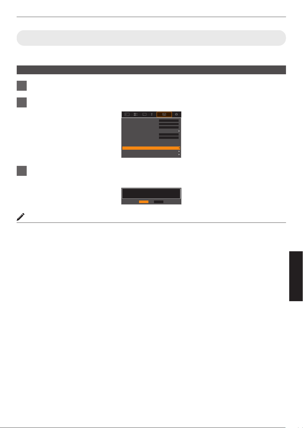
Resetting the Lamp Time 4 8
Reset the lamp time when you have replaced the lamp. It provides an estimated timing for lamp replacement
Resetting the lamp time from the menu screen
1
Press the [MENU] button to display the menu
2
Select “Function”"“Lamp Reset” from the menu
Factory Reset
Software Update
Off
Off
Off
A
Off
Lamp Reset
Remote Code
Network
High Altitude Mode
ECO Mode
Off Timer
Trigger
3
On the “Reset Lamp Time?” screen, select “Yes” and press the [OK] button
0
The lamp time is reset to zero.
NoYe s
Reset Lamp Time?
MEMO
0
Reset the lamp time only when you have replaced the lamp.
If the
lamp time is reset while a lamp is in use, you may lose track of the timing for replacing the lamp. Doing so may
result in using the lamp beyond the estimated limit, thereby causing lamp blowout.
93
Maintenance
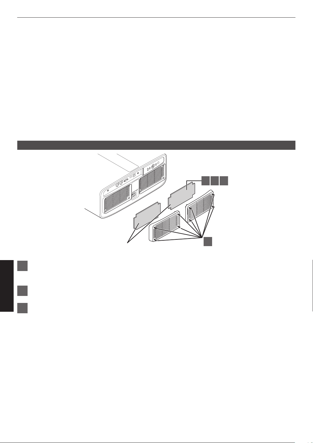
Maintaining the Cabinet and Remote Control
0
Gently wipe off dirt on the cabinet with a soft cloth.
0
If
it
is extremely dirty, wet a cloth in water, wring dry and use it to wipe off the dirt, followed by wiping again with a dry
cloth.
0
Pay attention to the following as the cabinet may deteriorate in condition or the paint may come off.
0
Do not wipe with thinner or benzine
0
Do not allow prolonged contact with rubber or plastic products
0
Do not spray volatile chemicals such as insecticide
Cleaning and Replacing the Filter
Clean the filter every 2000 hours (more often in dusty conditions). Using a filter without cleaning may reduce the
brightness of the image. Dirt that enters the unit may also appear as shadows on the image.
Replacing the Filter x y z 5 6 7
1
2 3 4
Sponge filter (gray)
1
Loosen the screws at the four corners and remove the cover
0
The screws cannot be removed from the cover. Do not try to remove the screws from the cover by force.
2
Remove the sponge filter
3
Use a vacuum cleaner to remove dirt from the sponge filter carefully
94
Maintenance
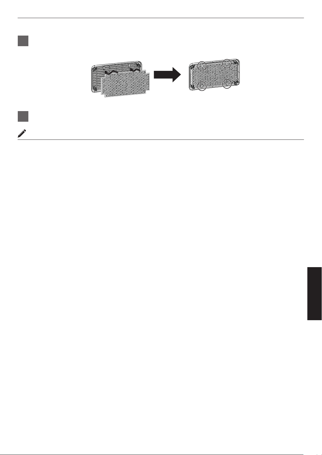
4
Restore the sponge filter to the original position
Place the sponge filter under the tabs
5
Restore the cover and fasten the screws at the four corners
MEMO
0
If
the
sponge filter is damaged and requires replacement, or if dirt gets into the unit, consult your authorized dealer
or nearby service center.
0
Sponge spacer
Product no.: J3K-0134-00
95
Maintenance
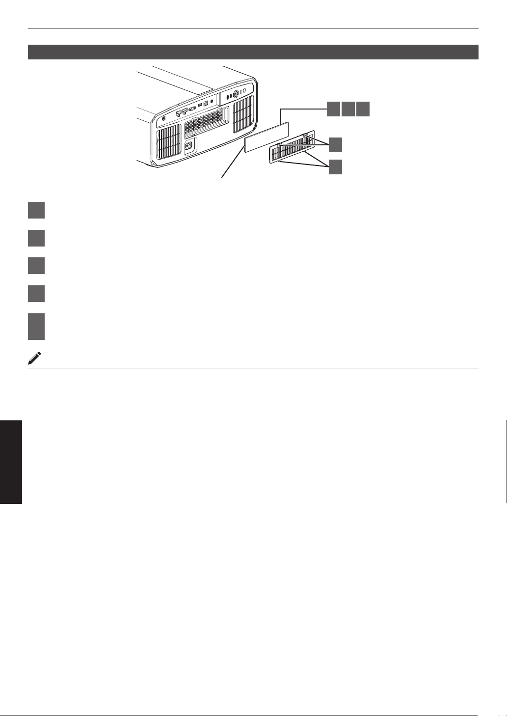
Replacing the Filter 4 8
2 3 4
1
5
Spon
g
e filter
1
Press down the two tabs on the cover and pull the cover out to remove the cover
2
Remove the sponge filter
3
Use a vacuum cleaner to remove dirt from the sponge filter carefully
4
Restore the sponge filter
5
Insert the catches at the bottom of the cover into the holes on the unit and replace
the cover
MEMO
0
If the
sponge filter is damaged and needs to be replaced or if dirt has entered the unit, please consult the authorized
dealer from which this unit is purchased or any nearby JVC servicing center.
* Be sure to attach the filter. Using this unit without attaching the filter may cause unexpected malfunction.
0
Sponge filter
Product no.: J3K-0094-00
96
Maintenance
Troubleshooting
Before sending the unit to your authorized dealer for repair, please check the following points.
The following symptoms are not malfunctions.
You do not need to worry about the following symptoms if there is no abnormality on the screen.
0
A part of the top or front surface of the unit is hot.
0
A creaking sound is heard from the unit.
0
An operating sound is heard from the inside of the unit.
0
Color smear occurs on some screens.
This unit is a digital device. This unit may become unable to operate normally due to external static or noise.
Perform the following operations when such malfunctions occur.
A
If the unit is in the Standby mode, pull out the power plug, followed by inserting it again
B
Press the A button on the projector unit to turn on the power again
When “High Altitude Mode” is set to “On”, and “Lamp Power” is set to “High” during 3D mode, the fan will
make louder noise than usual since it is designed to run at high speed in 3D mode.
Power is not supplied
Check Action Refer to
Is the power cord disconnected? Insert the power cord (plug) firmly. P. 32
Is the lamp cover properly shut?
4 8
If the unit is in the Standby mode, remove the power plug
and close
the lamp cover properly. After that, insert the plug
again.
P. 91
Is the unit in the Cool-down mode? After exiting the Cool-down mode, turn on the power again. P. 34
Is the unit in the Eco mode? Press the A button on the projector unit or the remote
control unit. After the “STANDBY/ON” indicator lights up in
red, press the C [ON] button.
P. 86
Power shuts down automatically
Check Action Refer to
Has “ECO Mode” been configured? Set “ECO Mode” to “Off”. P. 86
Has “Off Timer” been configured? Set “Off Timer” to “Off”. P. 86
Are the air inlets and exhaust vent
blocked?
Leave proper clearance when installing the unit. P. 21, 27
Is there a large amount of dirt attached to
the sponge filter?
Remove the dirt using a vacuum cleaner. P. 94
97
Troubleshooting
Video image does not appear
Check Action Refer to
Is the correct external input selected? Select the correct external input terminal. P. 33
Is the power of the AV device or PC
turned on?
Turn on the power of the AV device or PC and play the
video.
P. 30
Is the AV device or PC properly
connected?
Connect the AV device or PC properly. P. 30
Are the correct signals being output from
the AV device or PC?
Set the AV device or PC properly. P. 30
Is the cable in use an HDMI-certified
cable?
Use an Ultra High Speed HDMI Cable (supports 48 Gbps).
HDMI cable may be directional and some HDMI cables
require external
power. Please check the specifications of
the cable you are using.
P. 30
Is an intermediate device (AV amplifier,
divider, etc.) in use?
Change the sequence of turning on the source device,
intermediate device and the projector. And after turning on
each device, ensure that the signal output is stable before
turning on the next device. If the intermediate device does
not support compressed video transmission, configure the
DSC setting under “HDMI EDID Setting” to “Off”. If the
intermediate device does not support HDR10+, configure
the HDR10+ setting under “HDMI EDID Setting” to “Off”.
P. 76
Is an old source device in use? Change the resolution setting of the source device. For
details on how to change the setting, please refer to the
instruction manual of the source device. Also, try the
“B” “C” mode settings under “HDMI EDID Setting”.
P. 76
Is the input signal 2K (2048x1080)
24/25/30/60Hz?
If the input signal is 2K (2048x1080) 24/25/30/50/60Hz,
configure
the
“Mode” setting in “HDMI EDID Setting” to “B”.
P. 76
3D images do not appear
Check Action Refer to
Do you see two images displayed side by
side?
Set “3D Format” to “Side by Side”
Video images in the “Side by Side” format may not be
recognized automatically in the case of 3D video images.
P. 38
Is an intermediate device (AV amplifier,
divider, etc.) in use?
Connect the source device to the projector directly, and
check whether there is any improvement in the condition.
If the condition improves, it is likely that this is not caused
by malfunction of the projector.
P. 30
Is the cable in use an HDMI-certified
cable?
Use an HDMI-certified high-speed cable.
Also, use as short a cable as possible.
P. 30
Is the power of the 3D Glasses turned
on?
If you are using the PK-AG3 3D Glasses,
turn on the power
manually.
Check the
instruction
manual of
the 3D
Glasses and 3D
Synchro Emitter.
Are the 3D Glasses charged? Check the PK-AG3 battery of the 3D Glasses is charged.
Are the 3D Glasses and 3D Synchro
Emitter too far away from each other?
Position them at an appropriate distance.
Are the 3D Glasses synced? Check the 3D Glasses are synced.
98
Troubleshooting
3D video image looks unnatural
Check Action Refer to
Are there overlapping video images? If there are overlapping video images partially, this is due
to the crosstalk phenomenon.
In this case, adjust “Crosstalk Cancel” accordingly.
P. 38
If there are overlapping video images partially, this is due
to the crosstalk phenomenon.
It may
be improved by changing “LD Power”/“Lamp Power”
to “High”.
P. 64
Video image looks unnatural
Colors are unnatural
Check Action Refer to
Is the color space of the input signal
correctly set?
The color may turn out unnatural when the input signal is
different from that in the projector setting.
Set the “Color Space” for “Input Signal” correctly.
P. 74
Is the image correctly adjusted? Adjust “Color” and “Tint” accordingly.
Check Picture Settings.
P. 66
Is the AV device or PC properly
connected?
Connect the AV device or PC properly. P. 30
* The video image may appear slightly reddish immediately after starting up. This is not a malfunction.
Video image is fuzzy
Check Action Refer to
Is the focus correctly adjusted? Adjust the focus. P. 35
Is the unit placed too near or too far away
from the screen?
Set the unit at a correct distance from the screen. P. 109
Video image flickers
Check Action Refer to
Do you see horizontally-extended,
overlapping video images?
In this case, set “3D Format” to “Auto” P. 38
Are you viewing the video images under
a fluorescent light?
This is caused by interference between the 3D glasses with
the flickers of the fluorescent light.
View with the fluorescent light turned off.
—
Is “Dynamic CTRL” set to “Mode 1” or
“Mode 2”?
x y z 5 6 7
Set “Dynamic CTRL” to “Off” P. 65
Is “Aperture” set to “Auto 1” or “Auto 2”?
4 8
Set “Aperture” to “Manual” P. 65
Video format changes
Check Action Refer to
Is the cable in use an HDMI-certified
cable?
Depending on the quality of the cable in use, the signal from
the device connected may change to a receivable video
format. Make use of an HDMI cable with the Ultra High
Speed HDMI Cable certification (supports 48 Gbps).
P. 30
99
Troubleshooting
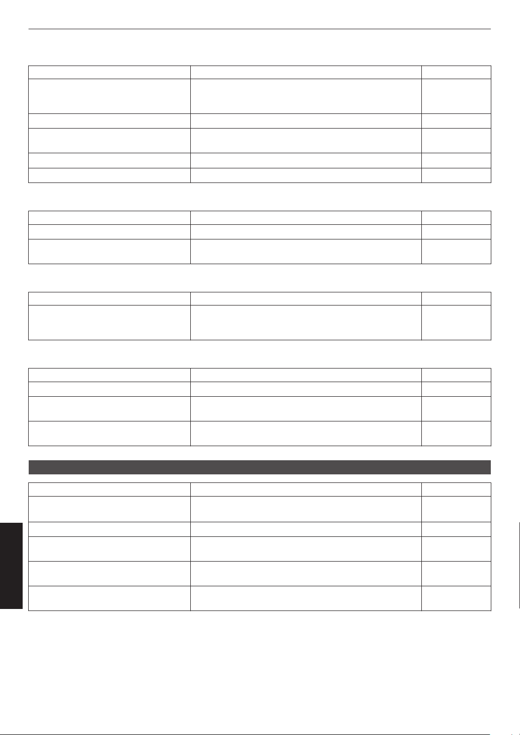
Projected image is dark
Check Action Refer to
Is the lamp near end of the rated hours?
4 8
Check the lamp time in the “Information” menu.
Prepare a new lamp unit or replace as soon as possible
when the lamp is near end of the rated hours.
P. 90
Is the aperture closed? Increase the value of the “Aperture” setting. P. 65
Is “LD Power”/“Lamp Power” set to
“Low”?
Set “LD Power”/“Lamp Power” to “High” P. 64
Is “Theater Optimizer” set to “On”? Press “Set” in the “Theater Optimizer” menu. P. 48
Check Picture Settings. Select different Picture Mode. P. 39
Video image appears horizontally (vertically) extended
Check Action Refer to
Is “3D Format” set to “Side by Side”? Set “3D Format” to “Auto” P. 38
Is “Anamorphic” set to a setting other
than “Off”?
Set “Anamorphic” to “Off” P. 83
Moire patterns appear on the screen
Check Action Refer to
Does the fabric of the screen have a
regular pattern?
Interference fringes may sometimes occur between the
fabric pattern
and the pixels. Please consult the authorized
dealer.
—
Part of the video Image is missing
Check Action Refer to
Has screen mask been configured? Set “Mask” to “Off”. P. 83
Is “Anamorphic” set to a setting other
than “Off”?
Set “Anamorphic” to “Off”. P. 83
Is “Aspect” set to a setting other than
“Native”?
Set “Aspect” to “Native” P. 36
Remote control does not work
Check Action Refer to
Are the batteries correctly installed? Match the polarities (t s) correctly when loading the
batteries.
P. 25
Are the batteries exhausted? Replace with new batteries. P. 25
Is there an obstructing object between
the remote control and remote sensor?
Remove any obstructing object. P. 25
Is the remote control held too far away
from the unit?
Hold the remote control closer to the sensor during use. P. 25
Is remote control code correctly? Match the settings of the projector and the remote control.
The factory settings are both “A”.
P. 88
100
Troubleshooting
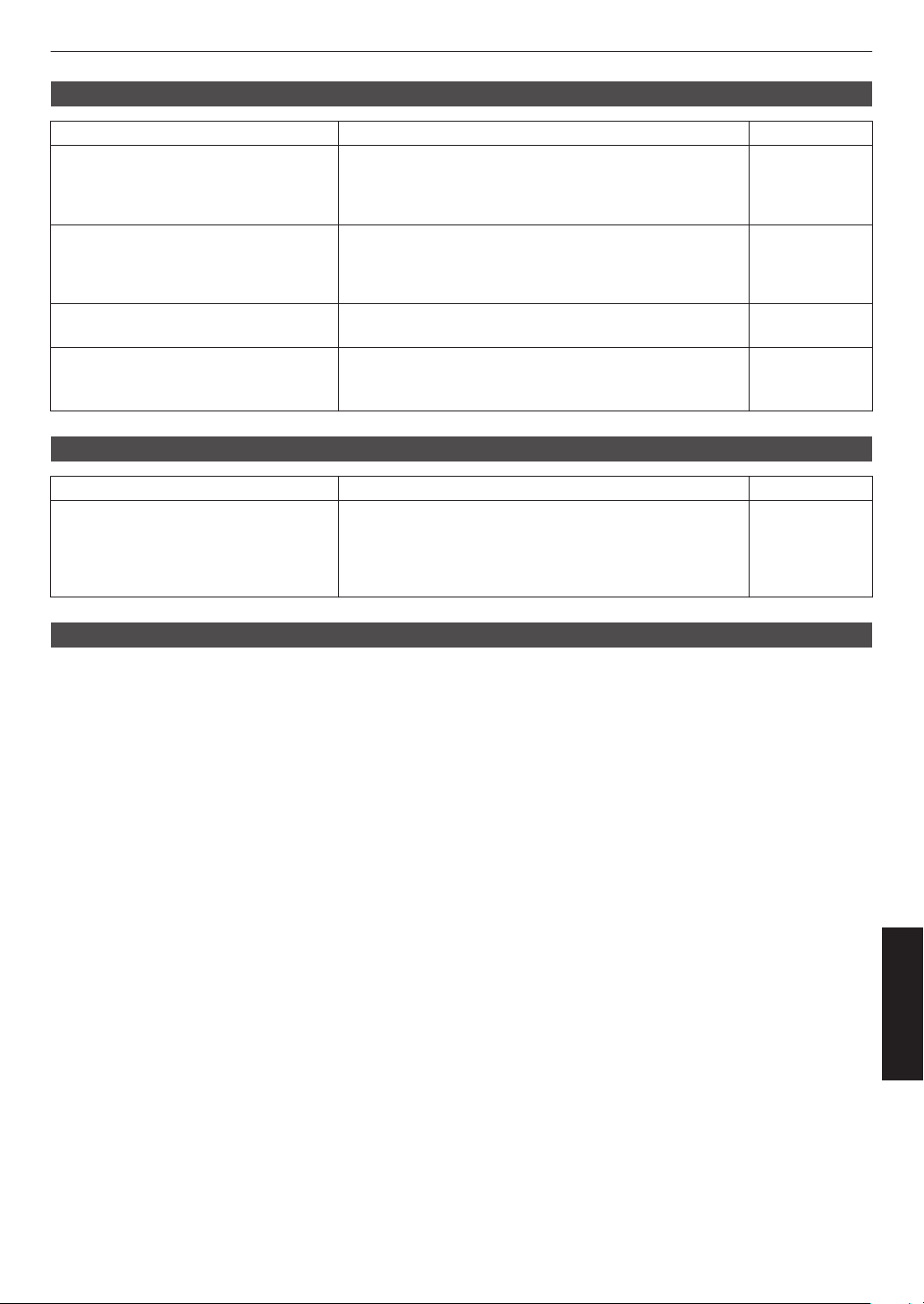
Noise is heard
Check Action Refer to
Is the exhaust vent blocked?
Is the unit used near a heater or air-
conditioner?
Check the installation condition of the projector.
When the
surrounding temperature of the projector is high,
the fan revolution speed increases to protect the projector
unit, hence a louder operating sound.
P. 27
Are you viewing 3D video images? “LD Power”/“Lamp Power” is set automatically to “High” to
ease viewing of 3D video images, hence a louder fan
operating sound.
If you are bothered by the sound, set it to “Low”.
P. 64
Is “LD Power”/“Lamp Power” set to
“High”?
Setting “LD Power”/“Lamp Power” to “High” increases the
fan rotation speed, and noise would be louder as a result.
P. 64
Is the “8K e-shift” setting for “MPC”
switched?
x y z 5 6 7
Switching sound is generated. This is not a malfunction.
—
Unable to connect to LAN terminal
Check Action Refer to
Has a network password been
configured? (DLA-NZ9BK,
DLA-NZ8BK,
DLA-NZ7BK, DLA-NP5BK, DLA-
RS4100K, DLA-RS3100K, DLA-
RS2100K, DLA-RS1100K)
Configuration of a network password is necessary before
connecting to the LAN terminal. Configure the network
password.
P. 87
There are small black or colored dots on the screen
The D-ILA device is manufactured using high-precision technologies, but there may be some (less than 0.01%) missing
pixels or pixels that remain permanently lit. This is not a malfunction.
101
Troubleshooting
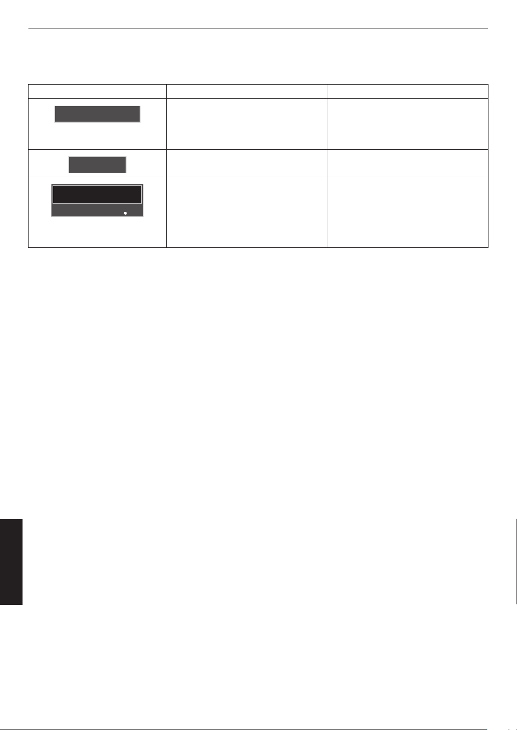
When the Following Messages Appear...
Message Description Action
No Input
0
No device is connected to the input
terminal.
0
The input terminal is connected but
there is no signal.
Input the video signals.
Out of Range
The video signal input is not supported
on this unit.
Input video signals that can be used.
(P.
113)
BACK
Back
Lamp replacement
Indicates that the lamp needs to be
replaced soon.
To clear
the message, press the [BACK]
button on the operation panel of the
projector unit or the remote control.
4 8
Get ready a new lamp unit and replace
as soon as possible. Reset the lamp time
after replacing the lamp. (P. 91, 93)
102
Troubleshooting
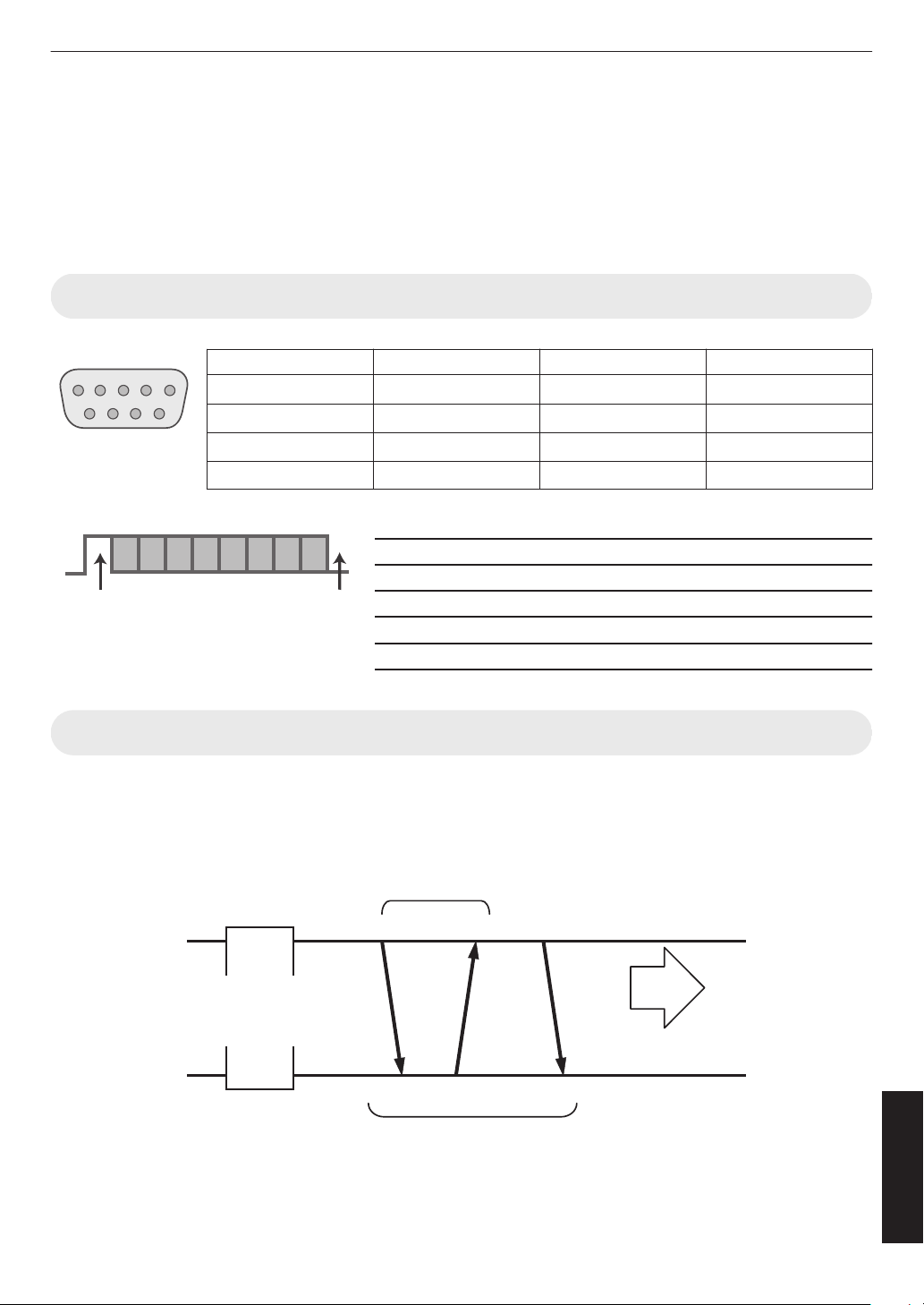
External Control
It is possible to control this unit by connecting it to a PC using an RS-232C cross cable (D-sub 9-pin).
The projector can be controlled by connecting it to a PC through the computer network with a LAN cable for control
commands to be sent to the projector.
Æ “Network” (P. 87)
0
Please use it after you have gained proper understanding from professional books or consulting the system
administrator.
RS-232C Specifications
Pin No. Signal Function Signal Direction
2 RxD Receive data PC " This unit
3 TxD Transmission data
This unit " PC
5 GND Signal ground
—
1, 4, 6 - 9 N/C
— —
0
PC refers to the controller, such as a personal computer.
Mode Non-synchronous
Character length 8 bit
Parity None
Start bit 1
Stop bit 1
Data rate 19200 bps
Data format Binary
15
69
This Unit
D6 D7D4 D5D2 D3D0 D1
Stop bitStart bit
TCP/IP Connection
Before controlling via LAN, it is necessary to establish connection of the TCP layer by a “3-way handshake”, followed
by sending
out “PJREQ” and receiving “PJACK” within five seconds after the projector sends out “PJ_OK” for connection
authentication.
If you are unable to complete sending within five seconds, or when “PJ_NG” or “PJNAK” is received, check the operating
status of the projector, followed by performing the steps again starting from establishment of a TCP connection.
Projector Control
Connection Authentication Procedure
PJACK
PJREQ
PJ_OK
Within 5 Seconds
Controlling PC
3-way Handshake
TCP Port No. 20554
Establishment of TCP Connection
Projector
103
Others
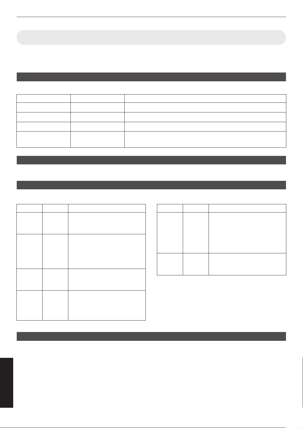
Command Format
The command between this unit and the computer consists of “Header”, “Unit ID”, “Command”, “Data” and “End”.
0
Header (1 byte), Unit ID (2 bytes), Command (2 bytes), Data (n bytes), End (1 byte)
Header
This binary code indicates the start of communication.
Binary Code Type Description
21 Operating command PC " This unit
3F Reference command
PC " This unit
40 Response command
This unit " PC
06 ACK This unit " PC (returns to PC after the command is accepted without
error)
Unit ID
This is a code that specifies the unit. The binary code is fixed at “8901”.
Command and data
Operating command and data (binary code)
Command
Type Description
0000
Connection
check
Check whether communication is
enabled between this unit and the
PC during standby.
5057 Power
supply
During standby
31: Turns on the power
When power is on
30: Turns off the power (Standby
mode)
4950 Input When power is on
36: HDMI 1
37: HDMI 2
5243 Remote
control
Sends the same code as the
supplied remote control.
0
“Remote Control
Code”P. 105
Reference command and data (binary code)
Command
Type Description
5057 Power
supply
During standby or when power is
on
30: Standby mode
31: When power is on
32: In the Cool-down mode
34: When
error occurs on this unit
4950 Input When power is on
36: HDMI 1
37: HDMI 2
End
This code indicates the end of communication. The binary code is fixed at “0A”.
104
Others
Remote Control Code
Binary code is sent during communication.
0
The following applies to the case when the remote control code is “A”. In the case of “B”, add “36” to the beginning
of the code.
Remote Control Button
Name
Binary Code
STANDBY 37 33 30 36
ON 37 33 30 35
INPUT 37 33 30 38
SETTING MEMORY 37 33 44 34
LENS CONTROL 37 33 33 30
HIDE 37 33 31 44
INFO. 37 33 37 34
J
37 33 30 31
K
37 33 30 32
I
37 33 33 34
H
37 33 33 36
Remote Control Button
Name
Binary Code
OK 37 33 32 46
MENU 37 33 32 45
BACK 37 33 30 33
PICTURE MODE 37 33 46 34
COLOR PROFILE 37 33 38 38
GAMMA SETTINGS 37 33 46 35
C.M.D. 37 33 38 41
MPC 37 33 46 30
ADVANCED MENU 37 33 37 33
105
Others
Communications Example
This section shows the communication examples of RS-232C.
Operating command
Type Command Description
Connection check PC " This unit: 21 89 01 00 00 0A
This unit "
PC: 06 89 01 00 00 0A
Connection check
Power (On) PC " This unit: 21 89 01 50 57 31 0A
This unit "
PC: 06 89 01 50 57 0A
When power is turned on from the
Standby mode
Power (Off) PC " This unit: 21 89 01 50 57 30 0A
This unit "
PC: 06 89 01 50 57 0A
When power is turned off (Standby
mode) from power-on mode
Remote control
(MENU)
PC " This unit: 21 89 01 52 43 37 33 32 45 0A
This unit
" PC: 06 89 01 52 43 0A
When the same operation as
pressing the [MENU] button on the
remote control is performed
Reference command
Type Command Description
Power (On) PC " This unit: 3F 89 01 50 57 0A
This unit "
PC: 06 89 01 50 57 0A
This unit " PC: 40 89 01 50 57 31 0A
When information on the power-on
state is acquired
Input (HDMI 1) PC " This unit: 3F 89 01 49 50 0A
This unit " PC: 06 89 01 49 50 0A
This unit " PC: 40 89 01 49 50 36 0A
When information on HDMI 1 input
is acquired
106
Others
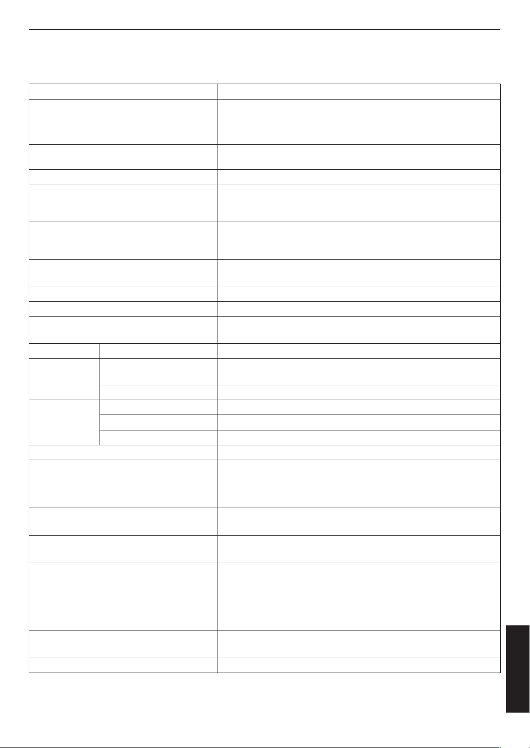
Specifications
Product Name D-ILA Projector
Model Name DLA-NZ9BK, DLA-NZ9BE, DLA-NZ8BK, DLA-NZ8BE, DLA-NZ7BK,
DLA-NZ7BE, DLA-RS4100K, DLA-RS4100E, DLA-RS3100K, DLA-
RS3100E, DLA-RS2100K, DLA-RS2100E, DLA-NP5BK, DLA-
NP5BE, DLA-NP5WE, DLA-RS1100K, DLA-RS1100E *1
Display Panel/Size D-ILA device *2, 3
0.69” 4K D-ILA (4096 x 2160 pixels) x 3
Projection Lens 2.0 x power zoom lens, motorized zoom and focus
Light Source Laser diode x y z 5 6 7
265 W ultra-high pressure mercury lamp (product no.: PK-L2618U)
Average lifespan: 4500 hours (“Low” mode) 4 8
Screen Size Approx. 60” to 280” (Aspect ratio of 16:9) x 5
Approx. 60” to 190” (Aspect ratio of 16:9)
y z 4 6 7 8
Brightness 3000 lm x 5, 2500 lm y 6, 2200 lm z 7,
1900 lm 4 8
Projection Distance Refer to P. 109.
Input Compatibility Signal Refer to P. 113.
Display Resolution 8192 x 4320 pixels (e-shift 8K) x y z 5 6 7
*4, 4096 x 2160 pixels 4 8
Input Terminal HDMI Input Dual, HDMI 19-pin x 2 (HDCP 2.3-compatible) *5
Output Terminal Trigger Terminal Single, Ø 3.5 mm DC Power Jack (E)
DC OUT 12 V, 0.1 A
3D synchro Dedicated terminal for 3D Synchro Emitter (single, mini-DIN 3-pin)
Control Terminal RS-232C Terminal Single, D-sub 9-pin (male) (external control)
LAN Terminal Single, RJ45 jack, 10BASE-T/100BASE-TX
Service Terminal SERVICE Single (USB Type A) *6
Power Requirements AC 100 V to 240 V, 50 Hz/60 Hz
Power Consumption 440 W (during network standby: 1.5 W *7, during Eco Mode standby:
0.3 W *8) x y 5 6
420 W (during network standby: 1.5 W *7, during Eco Mode standby:
0.3 W *8) z 4 7 8
Operation Environment Temperature: 5°C to 35°C; humidity: 20% to 80%; storage
temperature: -10°C to 60
°C
Installation Altitude
Not higher than 6,561 ft (2,000 m)
x
y
z
5
6
7
or 5,000 ft (1,524 m)
4
8
Dimensions (Width x Height x Depth) 500 mm x 234 mm x 528 mm (19-3/4 in x 9-1/4 in x 20-13/16 in)
(including feet) x 5
500 mm x 234 mm x 505 mm (19-3/4 in x 9-1/4 in x 19-15/16 in)
(including feet) y z 6 7
500
mm
x 234 mm x 495 mm (19-3/4 in x 9-1/4 in x 19-1/2 in) (including
feet) 4 8
Mass 25.3 kg (55.7 lb) x 5, 23.1 kg (50.9 lb) y 6, 22.5 kg
(49.6 lb) z 7, 19.2 kg (42.3 lb) 4 8
Accessories Refer to P. 19.
107
Others
*1 “W” indicates that the main unit is white in color. “B” indicates that the main unit is black in color.
*2 D-ILA is the abbreviation for Direct Drive Image Light Amplifier.
*3
D-ILA devices are manufactured using extremely high-precision technology with a pixel effectiveness of 99.99%.
Only 0.01% or less of the pixels are either missing or would remain permanently lit.
*4 During 3D playback, the display resolution is 4096 x 2160 pixels.
*5 HDCP is the abbreviation for High-bandwidth Digital Content Protection system. The image of the HDMI input
terminal may not be displayed in some cases due to changes in the HDCP specifications.
*6 Exclusively for firmware update.
*7 The power consumption of this product during networked standby when all wired network ports are connected
is 1.5 W.
*8 “During standby” refers to Eco Mode standby (P. 86).
0
Design and specifications are subject to change without prior notice.
0
Please
note
that some of the pictures and illustrations may have been abridged, enlarged or contextualized in order
to aid comprehension. Images may differ from the actual product.
This unit has acquired the certification of the “HDR10+” standard set by HDR10 +
Technologies, LLC.
Tone mapping
is optimally performed for each scene according to the dynamic metadata to
faithfully reproduce HDR video images for viewing according to the intentions of the video
producer.
HDR10+
™
logo is a trademark of HDR10+ Technologies, LLC.
This unit is isf-certified, so calibration can be performed by an isf-certified trainer.
After calibration is performed, an isf mode is added to the Picture mode.
For more details, please refer to the isf website.
http://www.imagingscience.com/
®
About Trademarks and Copyrights
The terms HDMI and HDMI High-Definition Multimedia Interface, and the HDMI Logo are
trademarks or registered trademarks of HDMI Licensing Administrator, Inc. in the United
States and other countries.
108
Others
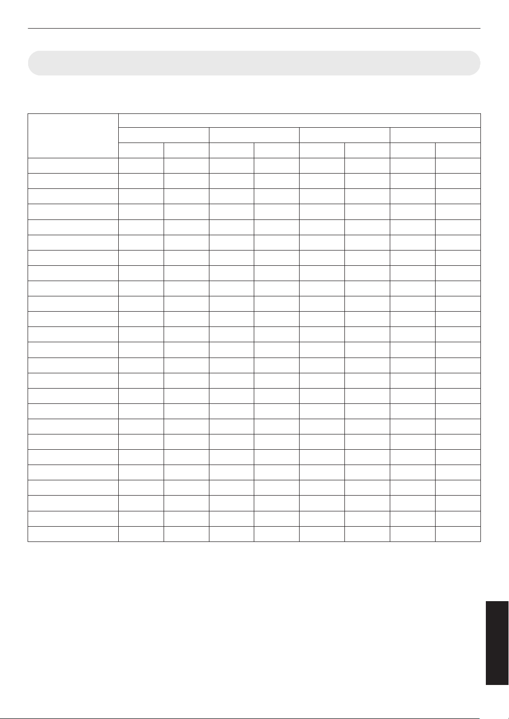
Screen Size and Projection Distance
x 5
Screen Size
Diagonal (Inch)
Projection Distance (m)
17:9 Screen 16:9 Screen 2.35:1 Screen 4:3 Screen
Wide-end Tele-end Wide-end Tele-end Wide-end Tele-end Wide-end Tele-end
60 1.67 3.43 1.75 3.61 1.86 3.82 2.16 4.44
70 1.96 4.02 2.06 4.23 2.18 4.47 2.54 5.19
80 2.25 4.60 2.37 4.84 2.50 5.12 2.91 5.94
90 2.54 5.19 2.67 5.46 2.83 5.77 3.29 6.70
100 2.83 5.77 2.98 6.07 3.15 6.41 3.66 7.45
110 3.12 6.36 3.28 6.69 3.47 7.06 4.04 8.20
120 3.41 6.94 3.59 7.30 3.79 7.71 4.41 8.95
130 3.70 7.53 3.90 7.92 4.12 8.36 4.79 9.71
140 3.99 8.11 4.20 8.53 4.44 9.01 5.16 10.46
150 4.28 8.70 4.51 9.15 4.76 9.66 5.53 11.21
160 4.58 9.28 4.81 9.76 5.09 10.31 5.91 11.96
170 4.87 9.87 5.12 10.38 5.41 10.96 6.28 12.72
180 5.16 10.45 5.43 10.99 5.73 11.61 6.66 13.47
190 5.45 11.04 5.73 11.61 6.05 12.26 7.03 14.22
200 5.74 11.62 6.04 12.22 6.38 12.91 7.41 14.98
210 6.03 12.21 6.34 12.84 6.70 13.56 7.78 15.73
220 6.32 12.79 6.65 13.45 7.02 14.21 8.16 16.48
230 6.61 13.38 6.96 14.07 7.35 14.85 8.53 17.23
240 6.90 13.97 7.26 14.68 7.67 15.50 - -
250 7.20 14.55 7.57 15.30 7.99 16.15 - -
260 7.49 15.14 7.87 15.91 8.32 16.80 - -
270 7.78 15.72 8.18 16.53 8.64 17.45 - -
280 8.07 16.31 8.48 17.14 - - - -
290 8.36 16.89 - - - - - -
300 8.65 17.48 - - - - - -
109
Others
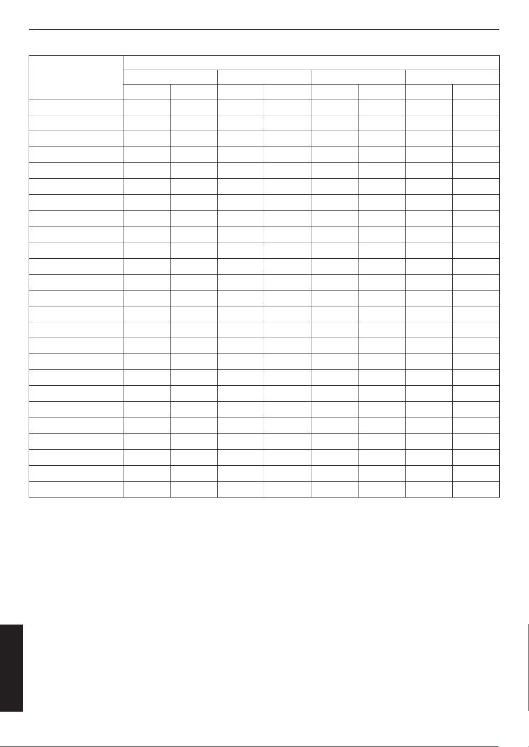
Screen Size
Diagonal (Inch)
Projection Distance (Inch)
17:9 Screen 16:9 Screen 2.35:1 Screen 4:3 Screen
Wide-end Tele-end Wide-end Tele-end Wide-end Tele-end Wide-end Tele-end
60 65.5 135.1 69.1 142.2 73.1 150.3 85.2 174.7
70 77.0 158.2 81.1 166.4 85.8 175.8 100.0 204.3
80 88.5 181.2 93.1 190.6 98.5 201.4 114.7 234.0
90 99.9 204.2 105.2 214.8 111.2 227.0 129.5 263.6
100 111.4 227.3 117.2 239.0 123.9 252.5 144.2 293.2
110 122.8 250.3 129.3 263.3 136.7 278.1 158.9 322.9
120 134.3 273.4 141.3 287.5 149.4 303.7 173.7 352.5
130 145.8 296.4 153.4 311.7 162.1 329.2 188.4 382.1
140 157.2 319.4 165.4 335.9 174.8 354.8 203.2 411.8
150 168.7 342.5 177.5 360.1 187.5 380.3 217.9 441.4
160 180.1 365.5 189.5 384.3 200.2 405.9 232.6 471.0
170 191.6 388.5 201.5 408.5 212.9 431.5 247.4 500.7
180 203.1 411.6 213.6 432.8 225.7 457.0 262.1 530.3
190 214.5 434.6 225.6 457.0 238.4 482.6 276.8 559.9
200 226.0 457.6 237.7 481.2 251.1 508.2 291.6 589.6
210 237.4 480.7 249.7 505.4 263.8 533.7 306.3 619.2
220 248.9 503.7 261.8 529.6 276.5 559.3 321.1 648.8
230 260.3 526.8 273.8 553.8 289.2 584.8 335.8 678.5
240 271.8 549.8 285.9 578.0 302.0 610.4 - -
250 283.3 572.8 297.9 602.2 314.7 636.0 - -
260 294.7 595.9 309.9 626.5 327.4 661.5 - -
270 306.2 618.9 322.0 650.7 340.1 687.1 - -
280 317.6 641.9 334.0 674.9 - - - -
290 329.1 665.0 - - - - - -
300 340.6 688.0 - - - - - -
110
Others
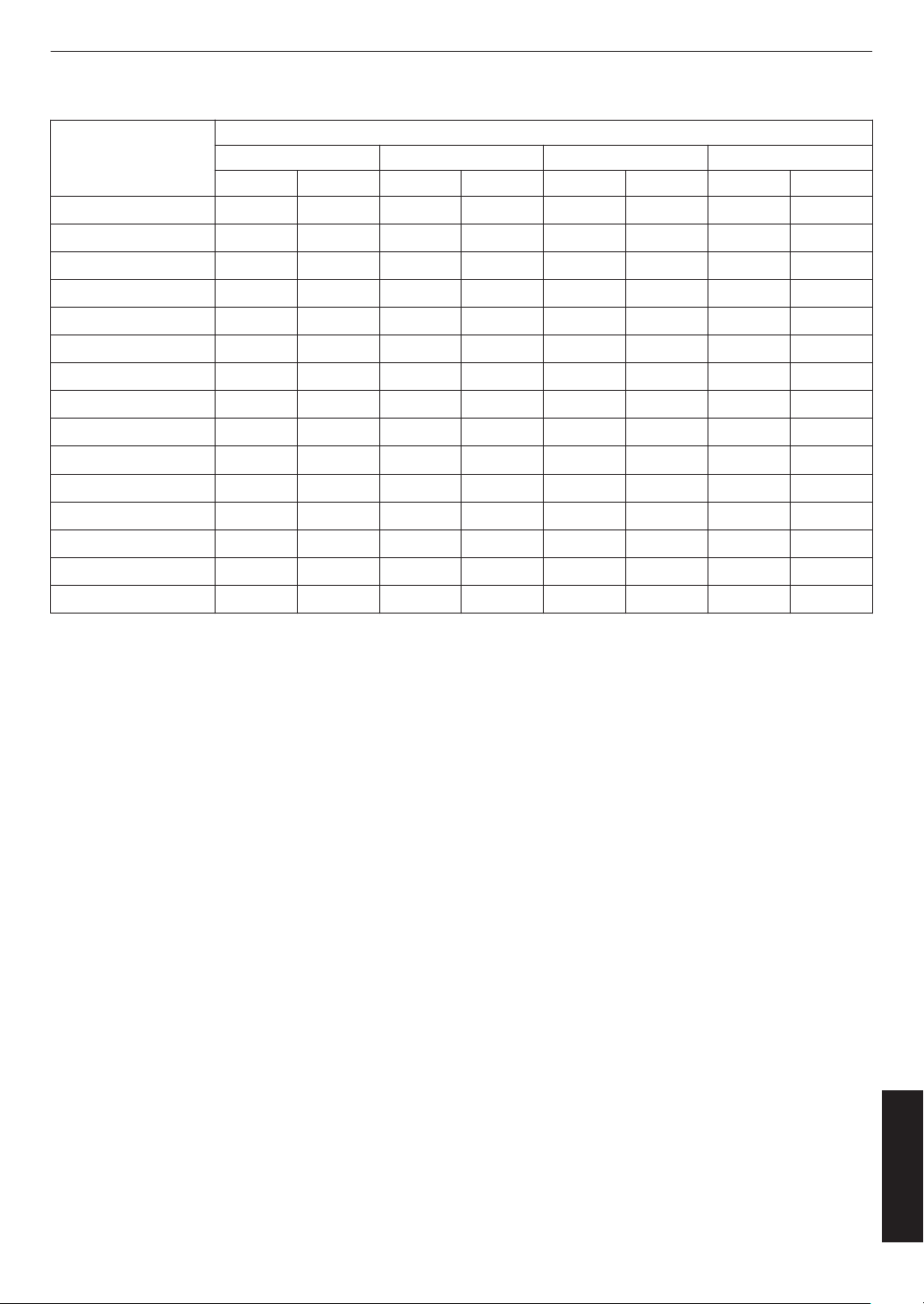
y z 4 6 7 8
Screen size
Diagonal (Inch)
Projection Distance (m)
17:9 Screen 16:9 Screen 2.35:1 Screen 4:3 Screen
Wide End Tele End Wide End Tele End Wide End Tele End Wide End Tele End
60 1.79 3.66 1.88 3.85 1.99 4.07 2.31 4.73
70 2.09 4.28 2.20 4.50 2.33 4.76 2.70 5.52
80 2.40 4.90 2.52 5.15 2.67 5.44 3.10 6.32
90 2.70 5.52 2.84 5.80 3.00 6.13 3.49 7.11
100 3.01 6.14 3.16 6.45 3.34 6.81 3.88 7.91
110 3.31 6.75 3.49 7.10 3.68 7.50 4.28 8.70
120 3.62 7.37 3.81 7.75 4.02 8.18 4.67 9.49
130 3.92 7.99 4.13 8.40 4.36 8.87 5.06 10.29
140 4.23 8.61 4.45 9.05 4.70 9.56 5.45 11.08
150 4.54 9.23 4.77 9.70 5.04 10.24 5.85 11.88
160 4.84 9.84 5.09 10.35 5.38 10.93 - -
170 5.15 10.46 5.41 11.00 5.72 11.61 - -
180 5.45 11.08 5.73 11.65 6.05 12.30 - -
190 5.76 11.70 6.05 12.30 - - - -
200 6.06 12.32 6.38 12.95 - - - -
111
Others

Screen Size
Diagonal (Inch)
Projection Distance (Inch)
17:9 Screen 16:9 Screen 2.35:1 Screen 4:3 Screen
Wide-end Tele-end Wide-end Tele-end Wide-end Tele-end Wide-end Tele-end
60 70.5 144.1 74.0 151.6 78.3 160.2 90.9 186.2
70 82.3 168.5 86.6 177.2 91.7 187.4 106.3 217.3
80 94.5 192.9 99.2 202.8 105.1 214.2 122.0 248.8
90 106.3 217.3 111.8 228.3 118.1 241.3 137.4 279.9
100 118.5 241.7 124.4 253.9 131.5 268.1 152.8 311.4
110 130.3 265.7 137.4 279.5 144.9 295.3 168.5 342.5
120 142.5 290.2 150.0 305.1 158.3 322.0 183.9 373.6
130 154.3 314.6 162.6 330.7 171.7 349.2 199.2 405.1
140 166.5 339.0 175.2 356.3 185.0 376.4 214.6 436.2
150 178.7 363.4 187.8 381.9 198.4 403.1 230.3 467.7
160 190.6 387.4 200.4 407.5 211.8 430.3 - -
170 202.8 411.8 213.0 433.1 225.2 457.1 - -
180 214.6 436.2 225.6 458.7 238.2 484.3 - -
190 226.8 460.6 238.2 484.3 - - - -
200 238.6 485.0 251.1 509.8 - - - -
112
Others
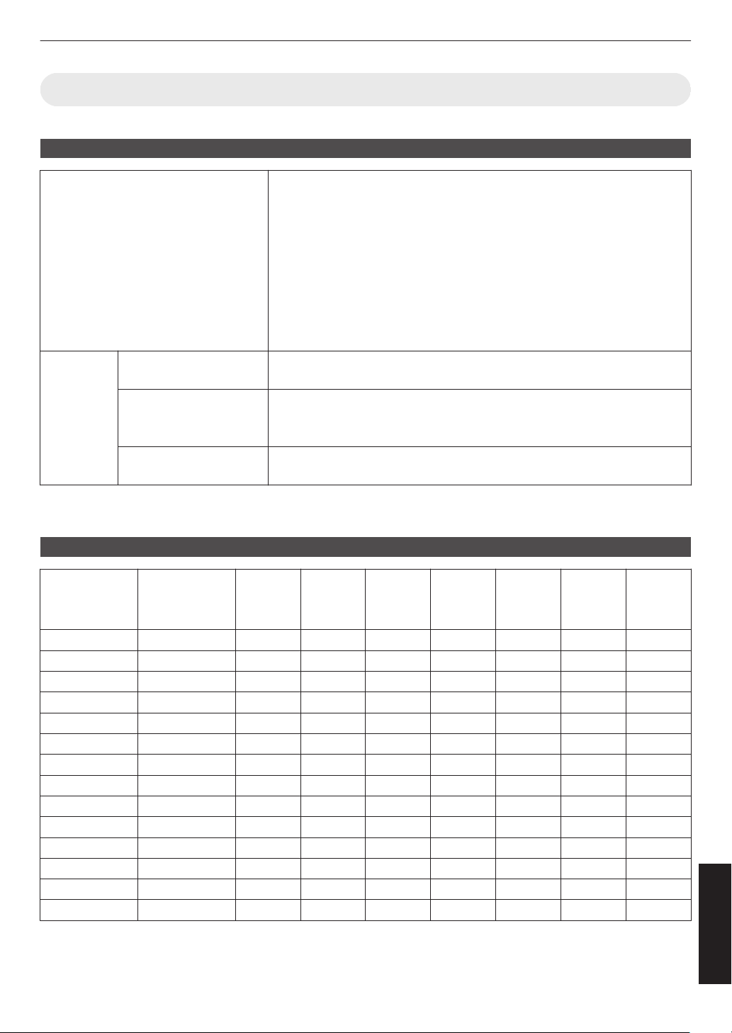
Types of Possible Input Signals
Video
Digital Video Signal 480p
576p
720p 50/60 Hz
1080i 50/60 Hz
1080p 24/25/30/50/60/100/120 Hz
2K (2048×1080) 24/25/30/50/60 Hz*
4K (3840×2160) 24/25/30/50/60/100/120 Hz
4K (4096×2160) 24/25/30/50/60/100/120 Hz
8K (7680×4320) 24/25/30/48/50/60 Hz
x y z 5 6 7
3D Signal Frame Packing 720p 50/60 Hz
1080p 24 Hz
Side-by-side 720p 50/60 Hz
1080p 50/60/24 Hz
1080i 50/60 Hz
Top-and-bottom 720p 50/60 Hz
1080p 24 Hz
* If the input signal is 2K (2048x1080) 24/25/30/50/60Hz, configure the “Mode” setting in “HDMI EDID Setting” to “B”.
(P.
76)
PC signal (HDMI)
Designation Resolution fh [kHz] fv [Hz]
dot CLK
[MHz]
Total No.
of Dots
[dot]
Total No.
of Lines
[line]
No. of
Effective
Dots [dot]
No. of
Effective
Lines
[line]
VGA 640×480 31.469 59.940 25.175 800 525 640 480
SVGA 800×600 37.879 60.317 40.000 1056 628 800 600
XGA 1024×768 48.363 60.004 65.000 1344 806 1024 768
WXGA 1280×768 47.776 59.870 79.500 1664 798 1280 768
WXGA 1280×800 49.702 59.810 83.500 1680 831 1280 800
FWXGA 1366×768 47.712 59.790 85.500 1792 798 1366 768
WXGA+ 1440×900 55.935 59.887 106.500 1904 934 1440 900
SXGA 1280×1024 63.981 60.020 108.000 1688 1066 1280 1024
WXGA++ 1600×900 60.000 60.000 108.000 1800 1000 1600 900
WSXGA+ 1680×1050 65.290 59.954 146.250 2240 1089 1680 1050
UXGA 1600×1200 75.000 60.000 162.000 2160 1250 1600 1200
WUXGA 1920×1200 74.556 59.885 193.250 2592 1245 1920 1200
WQHD 2560×1440 88.787 59.951 241.500 2720 1481 2560 1440
WQHD/120 2560×1440 183.000 120.000 497.760 2720 1525 2560 1440
* Even when signals can be input, video images may not be projected properly depending on the PC or cable in use.
When
this occurs, switching to another compatible resolution or changing the cable may help to resolve the problem
in some cases.
113
Others
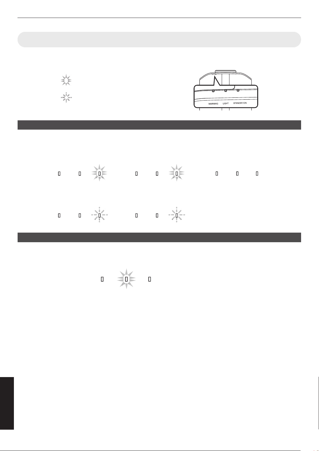
Indicator Display on the Main Unit
Meaning of the front panel indicators
The indicator appears blinking.
The indicator is solid.
Operation mode display
Displays using the different colors and solid/blinking light of the indicator on the projector unit.
LIGHT
STANDBY/ON
WARNING LIGHT
STANDBY/ON
WARNING
LIGHT
STANDBY/ON
WARNING LIGHT
STANDBY/ON
WARNING
LIGHT
STANDBY/ON
WARNING
DB
TAN
BY/O
DB
TAN
BY/O
D
D
Y/O
A
ANDBY/O
When in “ECO Mode”
When the video image is
temporarily hidden (HIDE is on)
During projection
All lights off
In the Cool-down mode
“STANDBY/ON” blinking (red)
When light source is starting up
“STANDBY/ON” lights up (green)
In standby state
“STANDBY/ON” lights up (red)
“STANDBY/ON” blinking (green)
・
・
・
・
・
・
Estimated timing for lamp replacement 4 8
Displays using the solid/blinking light of the “LIGHT” indicator. The “STANDBY/ON” indicator, which shows the operating
mode of the unit, is displayed simultaneously as described above.
LIGHT
STANDBY/ON
WARNING
GH
LIG
HT
“LIGHT” lights up (orange)
When lamp replacement is
near
114
Others
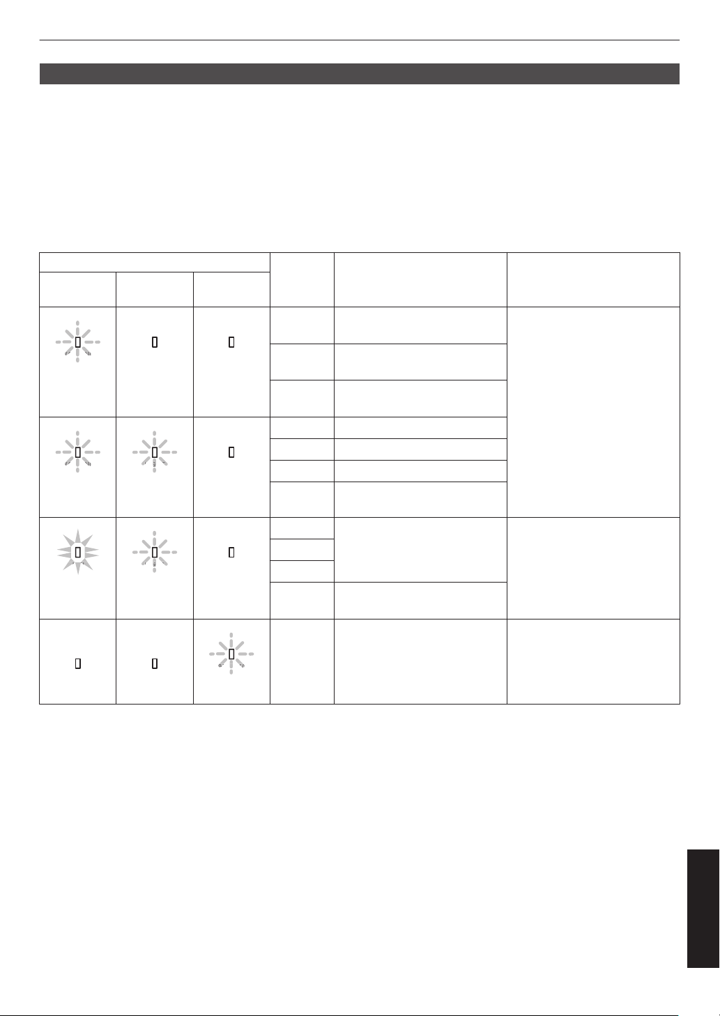
Warning display
You can tell the details of a warning from the (repeated) displays of the “WARNING” and “LIGHT” indicators. The
“STANDBY/ON” indicator
will light up or appear blinking according to the operation mode of the projector unit. (Please
refer to ““Operation mode display”P. 114”.)
The Warning mode is activated once the message is displayed. Projection is interrupted and the cooling fan starts
running.
The power cannot be turned on again while cooling is in progress. Check the following after cooling is complete.
If the Warning mode is activated again, wait for the cooling fan to stop, followed by pulling out the power plug from the
outlet. Then pull out the power plug from the power outlet. Call your authorized dealer for repair.
x y z 5 6 7
Indicator Status
Blinking
Frequency
Description Check and Countermeasure
WARNING LIGHT
STANDBY/
ON
WARNING
WARNING
(Red)
LIGHT
STANDBY/ON
Mode
Display
x2 Cooling fan stopped
abnormally
0
Check that nothing is
blocking the air inlets.
0
Check that the external
temperature is normal.
Countermeasure: Leave the
unit unoperated until it cools
down. After that, turn on the
power again.
x3 Internal temperature is
abnormally high
x4 External temperature is too
high
WARNING
WARNING
(Red)
LIGHT
LIGHT
(Orange)
STANDBY/ON
Mode
Display
x1 DD board occurs error
x2 Fan motor board occurs error
x3 CPU board occurs error
x4 Power board occurs error
WARNING
RN
WAR
NING
(Red)
LIGHT
LIGHT
(Orange)
STANDBY/ON
Mode
Display
x1 Abnormality in the light source Request for repair at your
authorized dealer or a nearby
service center.
x2
x3
x4 When the safety switch is
activated
WARNING
LIGHT
STANDBY/ON
ANDBY/O
(Green)
x3 The remote control code differs
between this unit and the
remote control
Set the remote control code for
this unit
and the remote control
correctly.
115
Others
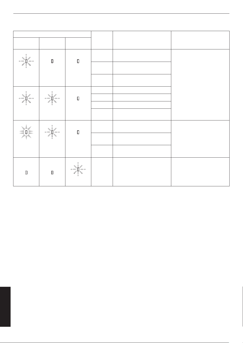
4 8
Indicator Status
Blinking
Frequency
Description Check and Countermeasure
WARNING LIGHT
STANDBY/
ON
WARNING
WARNING
(Red)
LIGHT
*
STANDBY/ON
Mode
Display
x2 Cooling fan stopped
abnormally
0
Check that nothing is
blocking the air inlets.
0
Check that the external
temperature is normal.
Countermeasure: Leave the
unit unoperated until it cools
down. After that, turn on the
power again.
x3 Internal temperature is
abnormally high
x4 External temperature is too
high
WARNING
WARNING
(Red)
LIGHT
LIGHT
(Orange)
STANDBY/ON
Mode
Display
x1 DD board occurs error
x2 Fan motor board occurs error
x3 CPU board occurs error
x4 Power board occurs error
WARNING
RN
WAR
NING
(Red)
LIGHT
LIGHT
(Orange)
STANDBY/ON
Mode
Display
x1 Lamp does not light up and unit
is unable to project
0
Check that the lamp unit
and lamp cover are
correctly installed.
Countermeasure: Turn on the
power again.
x2 Lamp goes out during
projection
x4 When the lamp cover is
removed
WARNING
LIGHT
STANDBY/ON
ANDBY/O
(Green)
x3 The remote control code differs
between this unit and the
remote control
Set the remote control code for
this unit
and the remote control
correctly.
(*) If the scheduled time for lamp replacement is exceeded, the indicator may light up.
116
Others
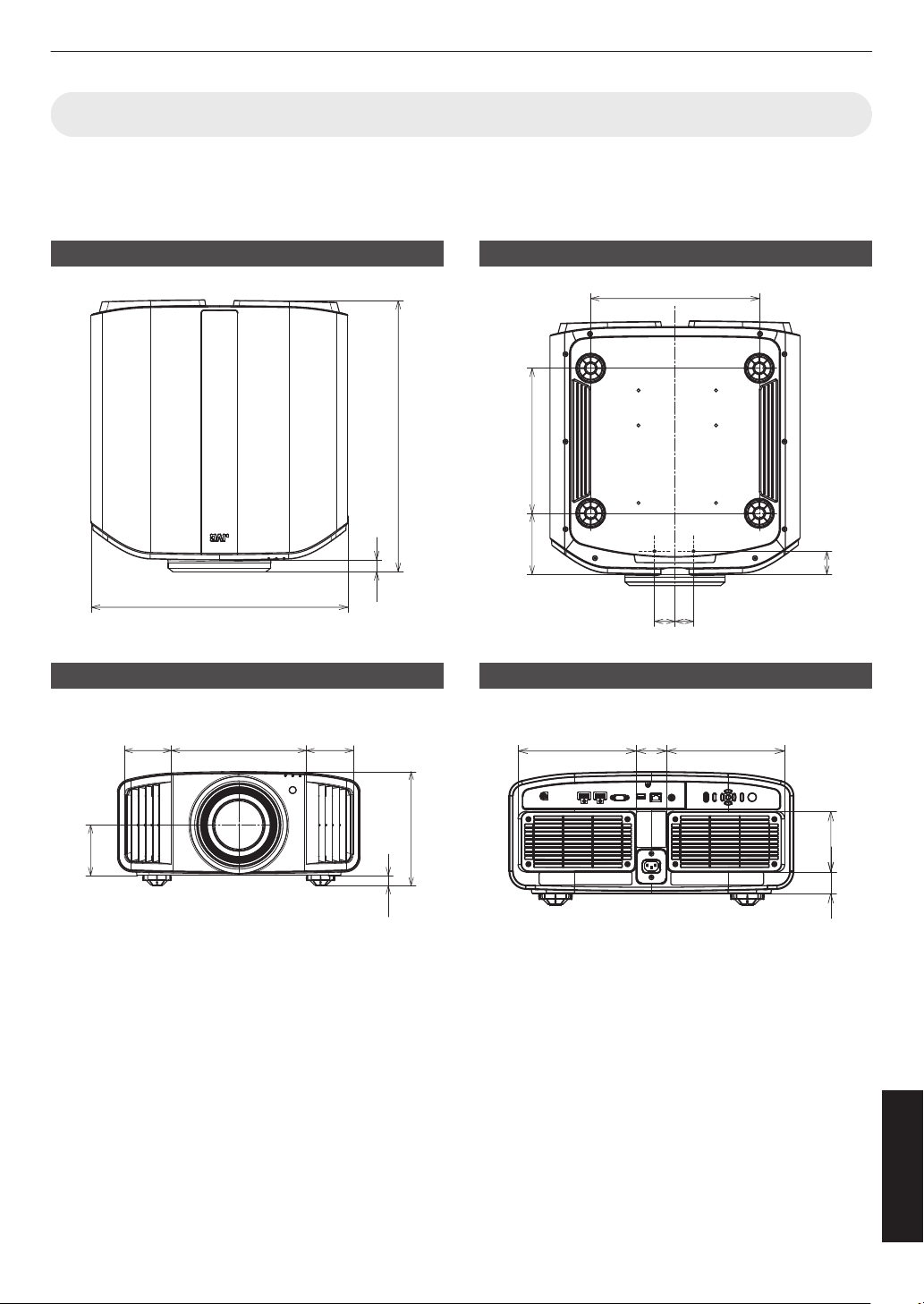
Dimensions
(Unit: mm)
x 5
Top Surface
500 (19-11/16)
528 (20-13/16)
23
(29/32)
Front
278
(10-15/16)
97
(3-27/32)
97
(3-27/32)
20
(13/16)
104
(4-1/8)
234 (9-7/32)
Bottom Surface
337 (13-9/32)
41
(1-5/8)
37
(1-15/32)
46
(1-13/16)
125
(4-15/16)
290
(11-7/16)
Rear Surface
207
(8-5/32)
207
(8-5/32)
54
(2-5/32)
106
(4-3/16)
39
(1-9/16)
117
Others
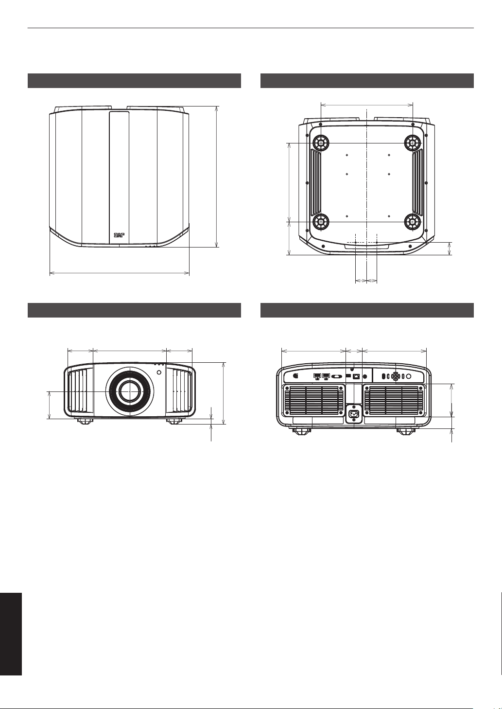
y z 6 7
Top Surface
500 (19-11/16)
505 (19-29/32)
Front
278
(10-15/16)
97
(3-27/32)
97
(3-27/32)
20
(13/16)
104
(4-1/8)
234 (9-7/32)
Bottom Surface
337 (13-9/32)
41
(1-5/8)
37
(1-15/32)
46
(1-13/16)
125
(4-15/16)
290
(11-7/16)
Rear Surface
207
(8-5/32)
207
(8-5/32)
54
(2-5/32)
106
(4-3/16)
39
(1-9/16)
118
Others
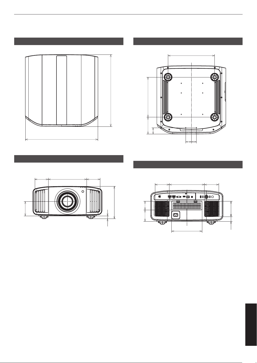
4 8
Top Surface
500 (19-11/16)
495 (19-1/2)
Front
278
(10-15/16)
97
(3-27/32)
97
(3-27/32)
20
(13/16)
104
(4-1/8)
234 (9-7/32)
Bottom Surface
337 (13-9/32)
41
(1-5/8)
37
(1-15/32)
46
(1-13/16)
125
(4-15/16)
290 (11-7/16)
Rear Surface
98
(3-7/8)
98
(3-7/8)
243
(9-19/32)
211
(8-5/16)
107
(4-7/32)
33
(1-5/16)
60
(2-3/8)
79
(3-1/8)
119
Others

Software License Agreement
The software embedded in the Product (hereinafter the “Licensed Software”) provided by JVCKENWOOD Corporation
(hereinafter the “Licensor”) is copyrighted to or sublicensable by the Licensor, and this Agreement provides for the
terms and
conditions which Users shall follow in order to use the Licensed Software. The User shall use the Licensed
Software by agreeing with the terms of this Software License Agreement. This Agreement shall be deemed completed
at the time the User (hereinafter the “User”) initially used the Product in which the “Licensed Software” is embedded.
The Licensed Software may include the software which has been licensed to the Licensor directly or indirectly from any
third party. In such case, some third parties require the Users to follow their conditions for use separately from this
Software License Agreement. Such software shall not be subject to this Agreement, and the Users are urged to read
the ““Important Notice concerning the Software”P. 122” to be provided separately.
Article 1 General Provision
The Licensor shall grant to the User a non-exclusive and non-transferable (other than the exceptional case referred to
in Article 3, Paragraph 1) licensed to use the Licensed Software within the country of the User (the country where the
User bought the Product (hereinafter the “Country”)).
Article 2 License
1. The license granted under this Agreement shall be the right to use the Licensed Software in the Product.
2.
The
User shall not duplicate, copy, modify, add, translate or otherwise alter, or lease the Licensed Software and any
related documents, whether in whole or in part.
3. The use of the Licensed Software shall be limited to personal purpose, and the Licensed Software shall not be
distributed, licensed or sub-licensed whether it is for commercial purpose or not.
4. The User shall use the Licensed Software according to the directions described in the operation manual or help file,
and is prohibited to use or duplicate any data in a manner violating the Copyright Law or any other laws and regulations
by applying whole or a part of the Licensed Software.
Article 3 Conditions for Grant of License
1. When the User transfers the Product, it may also transfer the license to use the Licensed Software embedded in the
Product (including
any related materials, updates and upgrades) on condition that no original, copies or related materials
continue in the possession of the User, and that the User shall cause the transferee to comply with this Software License
Agreement.
2. The User shall not carry out reverse engineering, disassembling, decompiling or any other code analysis works in
connection with the Licensed Software.
Article 4 Right pertaining to the Licensed Software
1. Any and all copyrights and other rights pertaining to the Licensed Software and related documents shall belong to
the Licensor or the original holder of the right who granted to the Licensor the license or sublicense for the Licensed
Software (hereinafter the “Original Rightholder”), and the User shall not be entitled to any right other than the license
granted hereunder, in respect of the Licensed Software and any related documents.
2. The User shall, whenever the User uses the Licensed Software, comply with any laws relating to the copyright and
other intellectual property rights.
Article 5 Indemnification of Licensor
1. Neither the Licensor nor the Original Rightholder shall be liable for any damage incurred by the User or any third
party due to the exercise of the license granted to the User under this Agreement, unless otherwise restricted by law.
2. The Licensor will offer no guarantee for the merchantability, convertibility and consistency with certain objective of
the Licensed Software.
Article 6 Liability to Third Party
If any dispute has arisen with any third party due to an infringement upon a copyright, patent or any other intellectual
property right that was caused by the User’s use of the Licensed Software, the User shall settle such dispute at the
User’s own cost and hold the Licensor and the Original Rightholder harmless from any inconvenience it may cause.
Article 7 Confidentiality
The User shall keep the confidentiality of such portion of the Licensed Software, related documents thereof or any other
information
to
be granted under this Agreement, as well as the conditions of this Agreement as has not yet entered the
public domain, and shall not disclose or divulge the same to any third party without approval of the Licensor.
120
Others

Article 8 Termination
In case
the User falls under any of the events described in the following items, the Licensor may immediately terminate
this Agreement or claim that the User compensates for the damage incurred by the Licensor due to such event:
(1) when the User violated any provision of this Agreement; or
(2) when a petition has been filed against the User for an attachment, provisional attachment, provisional disposition
or any other compulsory execution.
Article 9 Destruction of the Licensed Software
If this Agreement is terminated pursuant to the provision of Article 8, the User shall destroy the Licensed Software, any
related documents and copies thereof within two (2) weeks from such date of termination.
Article 10 Export Restriction
1. The User shall understand that the Licensed Software shall be subject to the export restrictions adopted by the
country of User and any other countries.
2. The User shall agree that the software will be subject to any and all applicable international and domestic laws
including the export control regulation of the country of User and any other countries, and any restrictions concerning
the end-users, the use by end-users and importing countries to be provided by the country of User and any other
countries, and any other governmental authorities.
3. If the User is an agency of the United States of America (the “Government”), the User acknowledge Licensor’s
representation that the Licensed Software is a “Commercial Item” as defined in Federal Acquisition Regulation (FAR)
part 2.101(g) consisting unpublished “Commercial Computer Software” as those items are used at FAR part 12.212
and
is
only license the User with the same use right Licensor grants all commercial end users pursuant to the terms of
this Agreement.
Article 11 Miscellaneous
1. In the event any part of this Agreement is invalidated by operation of law, the residual provisions shall continue in
force.
2. Matters not stipulated in this Agreement or any ambiguity or question raised in the construction of this Agreement
shall be provided or settled upon good-faith consultation between the Licensor and the User.
3. The Licensor and the User hereby agree that this Agreement is governed by the laws of Japan, and any dispute
arising from, and relating to the rights and obligations under, this Agreement shall be submitted to the exclusive
jurisdiction of the Tokyo District Court for its first instance.
121
Others

Important Notice concerning the Software
Software License Attached to the Product :
The Software embedded in the Product is composed of several independent software components, and in each of such
individual components (hereinafter the “Licensed Software”), a copyright of either JVCKENWOOD Corporation
(hereinafter “JKC”) or a third party subsists.
The
Product
uses the software component designated in the End-User License Agreement that was executed between
JKC and a third party (hereinafter “EULA”).
The Licensed Software covers those corresponding to free software, and, as a condition of distribution of the software
component in executable format which is based on the license granted under the GNU General Public License or Lesser
General Public License (hereinafter “GPL/LGPL”), it requires an availability of the source code for the relevant
component.
Please refer to the following URL concerning the distribution of the source code;
https://www3.jvckenwood.com/english/download/gpl/index.html
Please note that we are unable to answer any inquiry relating to the contents, etc. of the source code. In addition, the
Licensed Software includes the software developed or created independently by JKC and there exists an ownership
of JKC in such software and any accompanying documents, which is protected by the Copyright Law, any international
treaties and other applicable laws. As to matters concerning the handling by JKC of the software components, please
refer to the “Software License Agreement” attached hereto. Please note that any software component licensed under
“EULA” which is not subject to “GPL/LGPL,” and those developed or created independently by JKC shall not be subject
to the requirement for provision of the source code. The software component distributed under “GPL/LGPL” shall be
licensed to users without charge, and, therefore, no warranty is given for such software component, either express or
implied, within the scope of the applicable laws and regulations. Unless otherwise permitted by applicable laws and
regulations or agreed in written form, none of the owners of the copyright or persons entitled to alter or redistribute the
software component under the said license shall have any liability for any type of damage or loss resulting from the use
of or inability to use such software component. For further details of the conditions of use of such software component
or matters required to be complied with, please refer to the relevant “GPL/LGPL”.
Users are urged to read the details for the relevant license carefully before using the software component covered by
“GPL/LGPL” and embedded in the Product. Since the terms and conditions of individual licenses are provided by parties
other than JKC, the original English version will be displayed by the Product menu screen.
A
Turn on the power of the projector.
B
Press the [MENU] button.
C
Select [Function]"[License].
122
Others

Index
A
Accessories.......................................................... 19
Adjust (Pixel Adjust)
..............................................79
Adjust Area .......................................................... 79
Adjust Color ......................................................... 79
Adjust Pattern ...................................................... 79
Adjust Pattern Color ............................................. 79
Adjust (Fine) .........................................................79
Adjust (Pixel) ........................................................79
Adjusting Distortion of the Projection Screen........ 35
Adjusting the Position........................................... 29
Adjustments and Settings in the Menu..................61
Anamorphic ..........................................................83
Aperture ............................................................... 65
Aspect ..................................................................36
Auto Pic.Mode Select ...........................................75
Auto Tone Mapping ..............................................50
B
Back Color ........................................................... 85
BNR......................................................................
73
Bright Level
.............................................. 51, 57, 57
Brightness (Color Management)..................... 44, 67
Brightness (More Settings)................................... 66
C
Cleaning and Replacing the Filter......................... 94
Clear Motion Drive................................................ 60
Clear Motion Drive ......................................... 60, 73
Color .................................................................... 66
Color Management ........................................ 44, 67
Color Profile ................................................... 44, 67
Color Selection (Color Management)..............44, 67
Color Selection (Gamma/Tone Mapping)........57, 70
Color Space (Information).....................................90
Color Space (Input Signal).................................... 74
Color Temp. ......................................................... 67
Colorimetry .......................................................... 90
Connecting the Projector...................................... 30
Contrast ............................................................... 66
Controls and Features.......................................... 20
Correction Value (Color Temp.)............................ 69
Correction Value (Gamma/Tone Mapping)..... 58, 70
Crosstalk Cancel ..................................................38
D
Dark Level ................................................ 51, 57, 57
Default Gateway
..................................................
87
DHCP Client .........................................................87
Dimensions.........................................................117
Display Setup .......................................................85
DSC ..................................................................... 76
Dynamic CTRL
x y z 5 6 7 ................65
E
Eco Mode............................................................. 86
ECO Mode
...........................................................
86
Enhance ...............................................................73
External Control.................................................. 103
F
Factory Reset .......................................................89
Filter Product no.
...................................................
96
Focus ................................................................... 35
Frame Interpolation...............................................60
Function ............................................................... 86
G
Gain Blue ............................................................. 69
Gain Green .......................................................... 69
Gain Red ..............................................................69
Gamma .................................................... 54, 57, 70
Graphic Mode ...................................................... 73
H
H Frequency ........................................................ 90
HDMI EDID Setting .............................................. 76
HDR ..................................................................... 90
HDR Feature on This Unit..................................... 45
HDR Level ............................................................71
HDR Processing .................................................. 70
HDR10 ................................................................. 75
HDR10+ ...............................................................76
Hide Mode............................................................ 33
High Altitude Mode ...............................................89
HLG ..................................................................... 75
Hue ................................................................ 44, 67
I
Image Pattern .......................................................78
Indicator Display
................................................. 114
Information ...........................................................90
Input (Information).................................................90
Input Level (Input Signal)...................................... 74
Input Signal .......................................................... 74
Input Terminal....................................................... 23
Installation ............................................................77
Installation Method................................................27
Installation Mode ..................................................77
Installation Style ...................................................85
IP Address ........................................................... 87
K
Keystone ..............................................................85
L
Lamp Power 4 8
....................................
64
Lamp Reset 4 8 ............................... 89, 93
Lamp Time 4 8 .....................................90
Lamp Unit Part Number........................................ 92
Language .............................................................86
LD Power x y z 5 6 7 64
Lens......................................................................20
Lens Center ......................................................... 78
Lens Control ...................................................35, 78
Lens Cover........................................................... 19
123
Others

License ................................................................ 89
Light Source Time
x y z 5 6 7 ................
90
List of Menu Items.................................................
61
Lock ..................................................................... 78
Logo .....................................................................86
Low Latency ...................................................59, 73
M
MAC Address .......................................................87
Maintenance.........................................................
90
Mapping Level ..................................................... 72
Mask .................................................................... 83
Max CLL/Max FALL ............................................. 90
Menu.....................................................................26
Menu Position ...................................................... 85
MNR..................................................................... 73
Mode ....................................................................76
Mode Copy .......................................................... 77
Mode Select .........................................................77
More Settings .......................................................64
Motion Control ................................................59, 73
Motion Enhance ............................................. 60, 73
MPC Level 4 8 .....................................73
MPC/e-shift x y z 5 6 7
..............................................................................73
N
Name Edit ............................................................ 77
Network ................................................................
87
NR ........................................................................
73
O
Off Timer .............................................................. 86
Offset Blue ........................................................... 69
Offset Green ........................................................ 69
Offset Red ............................................................69
Optional Accessories............................................19
P
Parallax
................................................................ 38
Partial Adjustment (Zone Adjust).....................
79, 82
Picture Adjust .......................................................64
Picture Mode ..................................................39, 64
Picture Tone .............................................51, 57, 57
Pixel Adjust .......................................................... 79
Power Cord............................................... 19, 19, 32
Precautions during Installation.............................. 27
Projection Distance.............................................109
R
Remote Code .......................................................88
Remote Control.....................................................
24
Replacing the Lamp
4 8 ........................91
Resolution ............................................................90
S
Saturation .......................................................44, 67
Screen Adjust
.......................................................
84
Screen Aspect ..................................................... 84
Screen Gain ......................................................... 84
Screen No. ...........................................................84
Screen Setting ..................................................... 84
Screen Size and Projection Distance
..................
109
Screen Size(Diagonal) ......................................... 84
SDR(2D)/SDR(3D) ...............................................75
Securing (Mounting) the Projector........................ 28
Securing the Projector (Ceiling Mount)................. 28
Shift ......................................................................35
Signal Display....................................................... 90
Soft Ver. ............................................................... 90
Software Update .................................................. 89
Source ................................................................. 90
Specifications..................................................... 107
Signal Display ...................................................... 85
Subnet Mask ........................................................87
T
Theater Optimizer ................................................ 71
Tint .......................................................................
66
Tone Mapping
.................................... 51, 54, 57, 70
Trigger ................................................................. 86
Troubleshooting....................................................97
Types of Possible Input Signals.......................... 113
U
User Name Edit ....................................................66
V
V Frequency .........................................................90
Viewing 3D Movies...............................................
37
Viewing HDR Content........................................... 45
Viewing Videos..................................................... 33
W
When the Following Messages Appear...............102
Whole Adjust (Fine) ........................................79, 81
Whole Adjust (Pixel)
.............................................80
Z
Zoom ....................................................................35
Alphanumeric
3D Format ............................................................ 38
3D Glasses .....................................................
19, 37
3D Setting ...................................................... 38, 74
3D Synchro Emitter ........................................ 19, 37
8K e-shift x y z 5 6 7 73
124
Others

.
.
DLA-NZ9/DLA-NZ8/DLA-NZ7/DLA-NP5/
DLA-RS4100/DLA-RS3100/DLA-RS2100/DLA-RS1100
D-ILA PROJECTOR
© 2021
1021KSH-SW-XX
