
Instruction Manual
25cc/1.5 cu.in. 2-Cycle
17 Inch Cutting Path / 0.080 In. Line
GASOLINE WEEDWACKER ®
Model No.
358.745191
• Safety
• Assembly
• Operation
• Maintenance
• Parts List
• Espa_ol
For Occasional Use Only
WARNING:
Read and follow all Safety Rules and Operating
Instructions before first use of this product.
For answers to your questions about this product:
Call 7 am-7 pm, Mon.-Sat., or 10 am-7 pm, Sun.
1-800-235-5878 _.o._ listed are Central Time)
Sears, Roebuck and Co., Hoffman Estates, IL 60179 U.S.A.
530163730 11/11/02
Warranty Statement 2 Storage 16
Safety Rules 3 Troubleshooting Table 17
Assembly 9 Emissions Statement 18
Operation 10 Parts List 20
Maintenance 14 Spanish 22
Service & Adjustments 15 Parts and Ordering Back Cover
FULL ONE YEAR WARRANTY ON CRAFTSMAN ® GASOLINE POWERED
WEEDWACKER ® LINE TRIMMER.
For one year from the date of purchase, when this Craftsman Gasoline Powered
Weedwacker Line Trimmer is maintained, lubricated, and tuned up according to
the operating and maintenance instructions in this manual, Sears will repair, free
of charge, any defect in materials or workmanship.
This warranty excludes nylon line, spark plug, and air filter, which are expendable
parts and become worn during normal use.
If this Weedwacker Line Trimmer is used for commercial purposes, this warranty ap-
plies for only 90 days from the date of purchase. If this Weedwacker Line Trimmer is
used for rental purposes, this warranty applies for only 30 days from the date of pur-
chase. This warranty applies only while this product is in use in the United States.
WARRANTYSERVICE ISAVAILABLE BYRETURNINGTHE WEEDWACKERLINETRIMMER
TO THE NEARESTSEARS STOREOR SERVICECENTER INTHE UNITEDSTATES.
This warranty gives you specific legal rights, and you may also have other rights
which vary from state to state.
Sears, Roebuck and Co., D/817WA, Hoffman Estates, IL 60179
Only the following Gasoline Powered Combination Gardening Appliance power-
head models and their respective attachments have been Classified by Under-
writers Laboratories, Inc., in accordance with the applicable safety requirements.
Powerhead including trimmer attachment .................... 358.745191
Optional brushcutter attachment ............................ 358.792430
Optional blower attachment ................................ 358.792421
The following attachment is Lis!ed by Underwriter's Laboratories, Inc., in accor-
dance with UL Standard 1602, Gasoline-Engine-Powered, Rigid-Cutting Mem-
ber Edgers and Edge-Trimmers."
Optional edger attachment ................................. 358.792400
2
4re.WARNING: When using gar-
dening appliances, basic safety pre-
cautions must always be followed to
reduce the risk of fire and serious
injury. Read and follow all instructions.
This power unit can be dangerous! Op-
erator is responsible for following
instructions and warnings on unit and in
manual. Read entire instruction manual
before using unit! Be thoroughly familiar
with the controls and the proper use of
the unit. Restrict the use of this unit to
persons who have read, understand.
and will follow the instructions and
warnings on the unit and in the manual.
Never allow children to operate this unit.
INSTRUCTION SAFETY INFORMATION
MANUAL ON THE UNIT
DANGER: Never use blades
with line trimmer attachment. Never
use flailing devices with any attach-
ment. This unit (when used with sup-
plied line trimmer attachment) is de-
signed for line trimmer use only. Use
of any other accessories with line trim-
mer attachment will increase the risk
of injury.
O@@
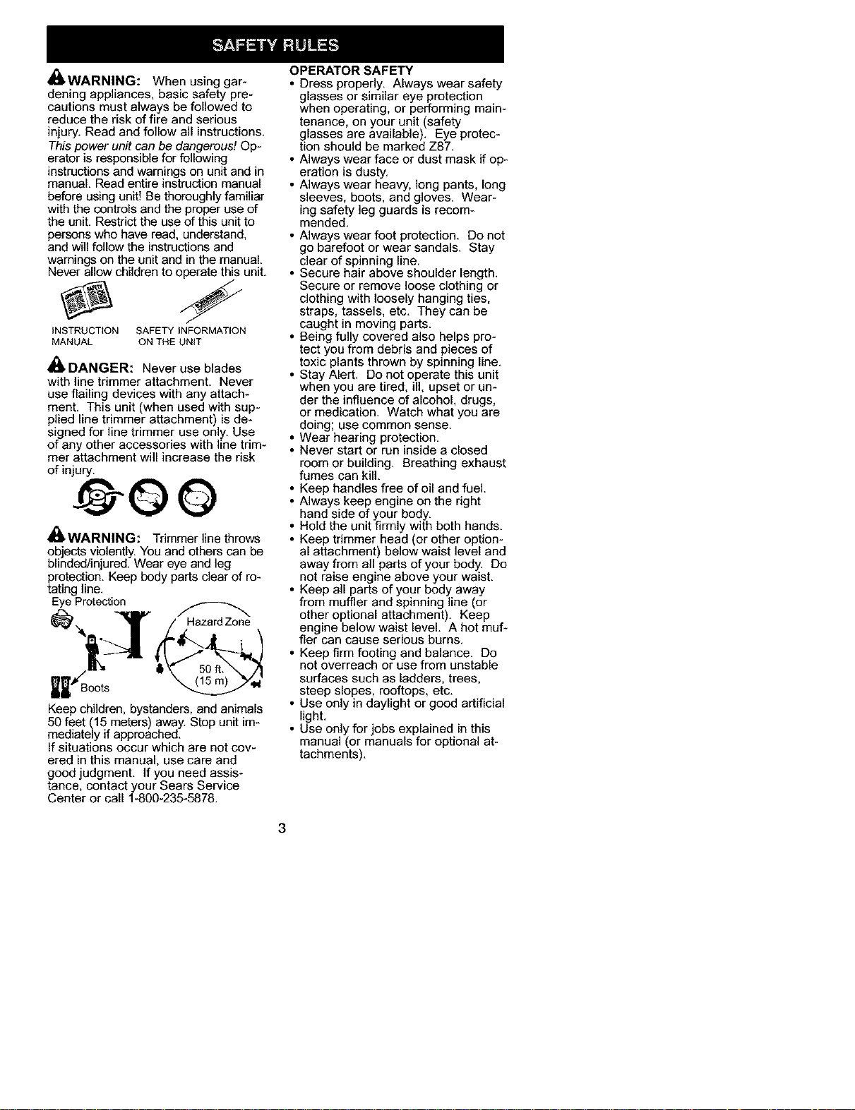
4re.WARNING: Trimmer line throws
objects violently. You and others can be
blinded/injured. Wear eye and leg
protection. Keep body parts clear of ro-
tating line.
Eye Protection
HazardZone
'.\--
Keep children, bystanders, and animals
50 feet (15 meters) away. Stop unit im-
mediately if approached.
If situations occur which are not cov-
ered in this manual, use care and
good judgment. If you need assis-
tance, contact your Sears Service
Center or call 1-800-235-5878.
OPERATOR SAFETY
• Dress properly. Always wear safety
glasses or similar eye protection
when operating, or performing main-
tenance, on your unit (safety
glasses are available). Eye protec-
tion should be marked Z87.
• Always wear face or dust mask if op-
eration is dusty.
• Always wear heavy, long pants, long
sleeves, boots, and gloves. Wear-
ing safety leg guards is recom-
mended.
• Always wear foot protection. Do not
go barefoot or wear sandals. Stay
clear of spinning line.
• Secure hair above shoulder length.
Secure or remove loose clothing or
clothing with loosely hanging ties,
straps, tassels, etc. They can be
caught in moving parts.
• Being fully covered also helps pro-
tect you from debris and pieces of
toxic plants thrown by spinning line.
• Stay Alert. Do not operate this unit
when you are tired, ill, upset or un-
der the influence of alcohol, drugs,
or medication. Watch what you are
doing; use common sense.
• Wear hearing protection.
• Never start or run inside a closed
room or building. Breathing exhaust
fumes can kill.
• Keep handles free ofoil and fuel.
• Always keep engine on the right
• hand side of your body.
Hold the unit firmly with both hands.
• Keep trimmer head (or other option-
al attachment) below waist level and
away from all parts of your body. Do
not raise engine above your waist.
• Keep all parts of your body away
from muffler and spinning line (or
other optional attachment). Keep
engine below waist level. A hot muf-
fler can cause serious burns.
• Keep firm footing and balance. Do
not overreach or use from unstable
surfaces such as ladders, trees,
steep slopes, rooftops, etc.
• Use only in daylight or good artificial
light.
• Use only for jobs explained in this
manual (or manuals for optional at-
tachments).
3
UNIT / MAINTENANCE SAFETY
• Disconnect the spark plug before
performing maintenance except car-
buretor adjustments.
• Look for and replace damaged or
loose parts before each use. Look
for and repair fuel leaks before use.
Keep in good working condition.
• Replace trimmer head parts that are
chipped, cracked, broken, or dam-
aged in any other way before using
the unit.
• Maintain unit according to recom-
mended procedures. Keep cutting
line at proper length.
• Use only 0.080 in.(2 mm) diameter
Craftsman® brand line. Never use
wire, rope, string, etc.
• Install required shield properly be-
fore using the unit. Use only speci-
fied trimmer head; make sure it is
properly installed and securely fas-
tened.
• Make sure unit is assembled cor-
rectly as shown in this manual.
• Make carburetor adjustments with
lower end supported to prevent line
from contacting any object.
• Keep others away when making car-
buretor adjustments.
• Use only recommended Craftsman
accessories and replacement parts.
• Have all maintenance and service
not explained in this manual per-
formed by a Sears Service Center.
FUEL SAFETY
• Mix and pour fuel outdoors.
• Keep away from sparks or flames.
• Use a container approved for fuel.
• Do not smoke or allow smoking near
fuel or the unit.
• Avoid spilling fuel or oil. Wipe up all
fuel spills.
• Move at least 10 feet (3 meters)
away from fueling site before start-
ing engine.
• Stop engine and allow to cool before
removing fuel cap.
• Always store gasoline in a container
approved for flammable liquids.
TRANSPORTING AND STORAGE
• Allow engine to cool before storing
or transporting in vehicle.
• Empty the fuel tank before storing or
transporting the unit. Use up fuel left
in the carburetor by starting the en-
gine and letting it run until it stops.
• Store unit and fuel in area where fuel
vapors cannot reach sparks or open
flames from water heaters, electric
motors or switches, furnaces, etc.
• Store unit so line limiter blade can-
not accidentally cause injury. The
unit can be hung by the tube.
• Store unit out of reach of children.
SAFETY NOTICE: Exposure to vibra-
tions through prolonged use of gaso-
line powered hand tools could cause
blood vessel or nerve damage in the
fingers, hands, and joints of people
prone to circulation disorders or ab-
normal swellings. Prolonged use in
cold weather has been linked to blood
vessel damage in otherwise healthy
people. If symptoms occur such as
numbness, pain, loss of strength,
change in skin color or texture, or loss
of feeling in the fingers, hands, or
joints, discontinue the use of this tool
and seek medical attention. An anti-
vibration system does not guarantee
the avoidance of these problems. Us-
ers who operate power tools on a con-
tinual and regular basis must monitor
closely their physical condition and
the condition of this tool.
SPECIAL NOTICE: This unit is
equipped with a temperature limiting
muffler and spark arresting screen
which meets the requirements of Cali-
fornia Codes 4442 and 4443. All U.S.
forest land and the states of California,
Idaho, Maine, Minnesota, New Jersey,
Oregon, and Washington require by
law that many internal combustion en-
igines be equipped with a spark arrest-
ng screen, if you operate in a locale
where such regulations exist, you are
legally responsible for maintaining the
operating condition of these parts.
Failure to do so is a violation of the
law. For normal homeowner use, the
muffler and spark arresting screen will
not require any service. After 50
hours of use, we recommend that your
muffler be serviced or replaced by a
Sears Service Center.
LINE TRIMMER SAFETY
_ WARNING: Inspect the area to
be trimmed before each use. Remove
objects (rocks, broken glass, nails,
wire, etc.) which can be thrown by or
become entangled in line. Hard ob-
jects can damage the trimmer head
and be thrown causing serious injury.
• Use only for trimming, scalping, mow-
ing and sweeping. Do not use for
edging, pruning or hedge trimming.
• Cut only from your right to your left.
Cutting on left side of the shield will
throw debris away from the operator.
4
ADDITIONAL SAFETY RULES
FOR OPTIONAL ATTACHMENTS
_ WARNING: For each optional
attachment used, read entire opera-
tors manual before use and follow all
warnings and instructions in manual
and on attachment.
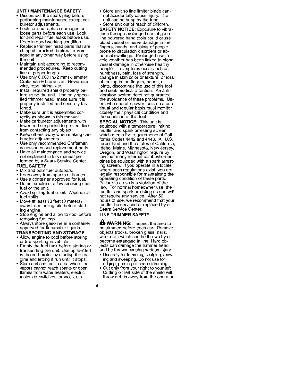
i_ WARNING: Ensure handlebar is
installed when using edger or brush-
cutter attachments. Attach handlebar
above arrow on safety label on the up-
per tube (engine end of unit). If your
edger or brushcutter attachment does
not include a handlebar, a handlebar
accessory kit (#530071451) is avail-
able from your Sears Service Center.
_Han61ebar
EDGER SAFETY
_WARNING: Inspect the area to
be edged before each use. Remove
objects (rocks, broken glass, nails,
wire, etc.) which can be thrown by the
blade or can wrap around the shaft.
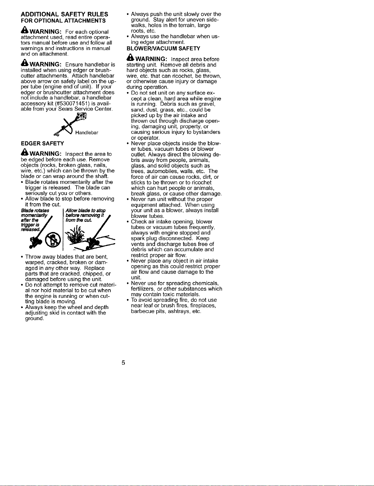
* Blade rotates momentarily after the
trigger is released. The blade can
seriously cut you or others.
* Allow blade to stop before removing
it from the cut.
Blade rotates
* Throw away blades that are bent,
warped, cracked, broken or dam-
aged in any other way. Replace
parts that are cracked, chipped, or
damaged before using the unit.
* Do not attempt to remove cut materi-
al nor hold material to be cut when
the engine is running or when cut-
ting blade is moving.
* Always keep the wheel and depth
adjusting skid in contact with the
ground.
• Always push the unit slowly over the
ground. Stay alert for uneven side-
walks, holes in the terrain, large
roots, etc.
• Always use the handlebar when us-
ing edger attachment.
BLOWER/VACUUM SAFETY
_WARNING: Inspect area before
starting unit. Remove all debris and
hard objects such as rocks, glass,
wire, etc. that can ricochet, be thrown,
or otherwise cause injury or damage
during operation.
• Do not set unit on any surface ex-
cept a clean, hard area while engine
is running. Debris such as gravel,
sand, dust, grass, etc., could be
picked up by the air intake and
thrown out through discharge open-
ing, damaging unit, property, or
causing serious injury to bystanders
or operator.
• Never place objects inside the blow-
er tubes, vacuum tubes or blower
outlet. Always direct the blowing de-
bris away from people, animals,
glass, and solid objects such as
trees, automobiles, walls, etc. The
force of air can cause rocks, dirt, or
sticks to be thrown or to ricochet
which can hurt people or animals,
break glass, or cause other damage.
• Never run unit without the proper
equipment attached. When using
your unit as a blower, always install
blower tubes.
• Check air intake opening, blower
tubes or vacuum tubes frequently,
always with engine stopped and
spark plug disconnected. Keep
vents and discharge tubes free of
debris which can accumulate and
restrict proper air flow.
• Never place any object in air intake
opening as this could restrict proper
air flow and cause damage to the
unit.
• Never use for spreading chemicals,
fertilizers, or other substances which
may contain toxic materials.
• To avoid spreading fire, do not use
near leaf or brush fires, fireplaces,
barbecue pits, ashtrays, etc.
5
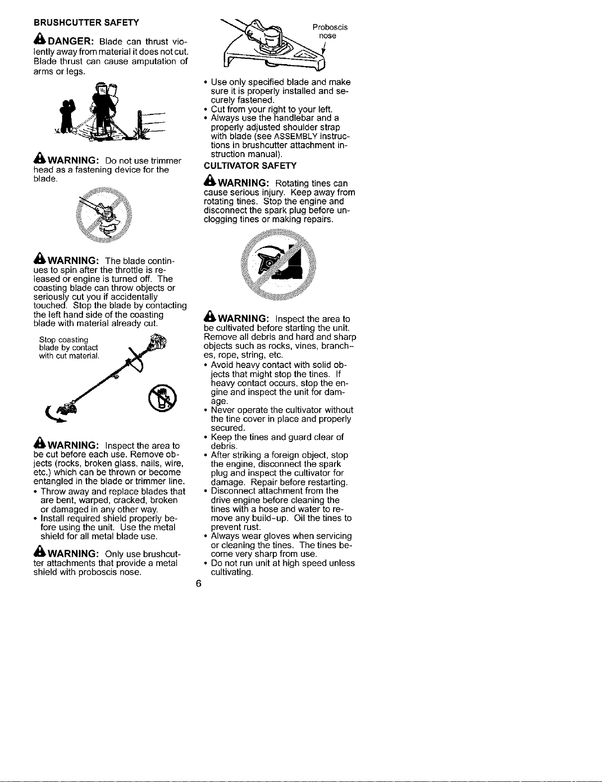
BRUSHCUTTER SAFETY
DANGER: Blade can thrust vio-
lently away from material it does not cut.
Blade thrust can cause amputation of
arms or legs.
_ WARNING: Do not use trimmer
head as a fastening device for the
blade.
se
• Use only specified blade and make
sure it is properly installed and se-
curely fastened.
• Cut from your right to your left.
• Always use the handlebar and a
properly adjusted shoulder strap
with blade (see ASSEMBLY instruc-
tions in brushcutter attachment in-
struction manual).
CULTIVATOR SAFETY
i_ WARNING: Rotating tines can
cause serious injury. Keep away from
rotating tines. Stop the engine and
disconnect the spark plug before un-
clogging tines or making repairs.
_ WARNING: The blade contin-
ues to spin after the throttle is re-
leased or engine is turned off. The
coasting blade can throw objects or
seriously cut you if accidentally
touched. Stop the blade by contacting
the left hand side of the coasting
blade with material already cut.
Stop coasting
blade by contact
with cut material,
®
4re.WARNING: Inspect the area to
be cut before each use. Remove ob-
jects (rocks, broken glass, nails, wire.
etc.) which can be thrown or become
entangled in the blade or trimmer line.
• Throw away and replace blades that
are bent. warped, cracked, broken
or damaged in any other way.
• Install required shield properly be-
fore using the unit. Use the metal
shield for all metal blade use.
_ WARNING: Only use brushcut-
ter attachments that provide a metal
shield with proboscis nose.
_ WARNING: Inspect the area to
be cultivated before starting the unit.
Remove all debris and hard and sharp
objects such as rocks, vines, branch-
es, rope, string, etc.
• Avoid heavy contact with solid ob-
jects that might stop the tines. If
heavy contact occurs, stop the en-
gine and inspect the unit for dam-
age.
• Never operate the cultivator without
the tine cover in place and properly
secured.
• Keep the tines and guard clear of
debris.
• After striking a foreign object, stop
the engine, disconnect the spark
plug and inspect the cultivator for
damage. Repair before restarting.
• Disconnect attachment from the
drive engine before cleaning the
tines with a hose and water to re-
move any build-up. Oil the tines to
prevent rust.
• Always wear gloves when servicing
or cleaning the tines. The tines be-
come very sharp from use.
• Do not run unit at high speed unless
cultivating.
6
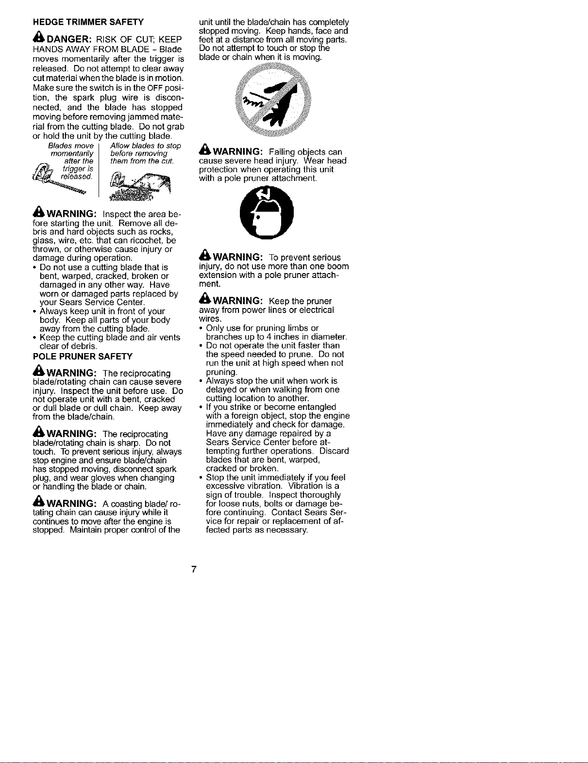
HEDGE TRIMMER SAFETY
DANGER: RISK OF CUT; KEEP
HANDS AWAY FROM BLADE - Blade
moves momentarily after the trigger is
released. Do not attempt to clear away
cut material when the blade is inmotion.
Make sure the switch is in the OFF posi-
tion, the spark plug wire is discon-
nected, and the blade has stopped
moving before removing jammed mate-
rial from the cutting blade. Do not grab
or hold the unit b
Blades move
momentarily
after the
trigger s
d,
! the cutting blade,
Allow blades to stop
before removing
them from the cut.
_ WARNING: Inspect the area be-
fore starting the unit. Remove all de-
bris and hard objects such as rocks,
glass, wire, etc. that can ricochet, be
thrown, or otherwise cause injury or
damage during operation.
* Do not use a cutting blade that is
bent, warped, cracked, broken or
damaged in any other way. Have
worn or damaged parts replaced by
your Sears Service Center.
* Always keep unit in front of your
body. Keep all parts ofyour body
away from the cutting blade.
* Keep the cutting blade and air vents
clear of debris.
POLE PRUNER SAFETY
i_ WARNING: The reciprocating
blade/rotating chain can cause severe
injury. Inspect the unit before use. De
not operate unit with a bent, cracked
or dull blade or dull chain. Keep away
from the blade/chain.
WARNING: The reciprocating
blade/rotating chain is sharp. Do not
touch. To prevent serious injury, always
stop engine and ensure blade/chain
has stopped moving, disconnect spark
plug, and wear gloves when changing
or handling the blade or chain.
_WARNING: A coasting blade/ro-
tating chain can cause injury while it
continues to move after the engine is
stopped. Maintain proper control of the
unit until the blade/chain has completely
stopped moving. Keep hands, face and
feet at a distance from all moving parts.
Do not attempt to touch or stop the
blade or chain when it is moving.
_ WARNING: Falling objects can
cause severe head injury. Wear head
protection when operating this unit
with a pole pruner attachment.
_WARNING: To prevent serious
injury, do not use more than one boom
extension with a pole pruner attach-
ment.
_ WARNING: Keep the pruner
away from power lines or electrical
wires.
• Only use for pruning limbs or
branches up to 4 inches in diameter.
• Do not operate the unit faster than
the speed needed to prune. Do not
run the unit at high speed when not
pruning.
• Always stop the unit when work is
delayed or when walking from one
cutting location to another.
• If you strike or become entangled
with a foreign object, stop the engine
immediately and check for damage.
Have any damage repaired by a
Sears Service Center before at-
tempting further operations. Discard
blades that are bent, warped,
cracked or broken.
• Stop the unit immediately if you feel
excessive vibration. Vibration is a
sign of trouble. Inspect thoroughly
for loose nuts, bolts or damage be-
fore continuing. Contact Sears Ser-
vice for repair or replacement of af-
fected parts as necessary.
7
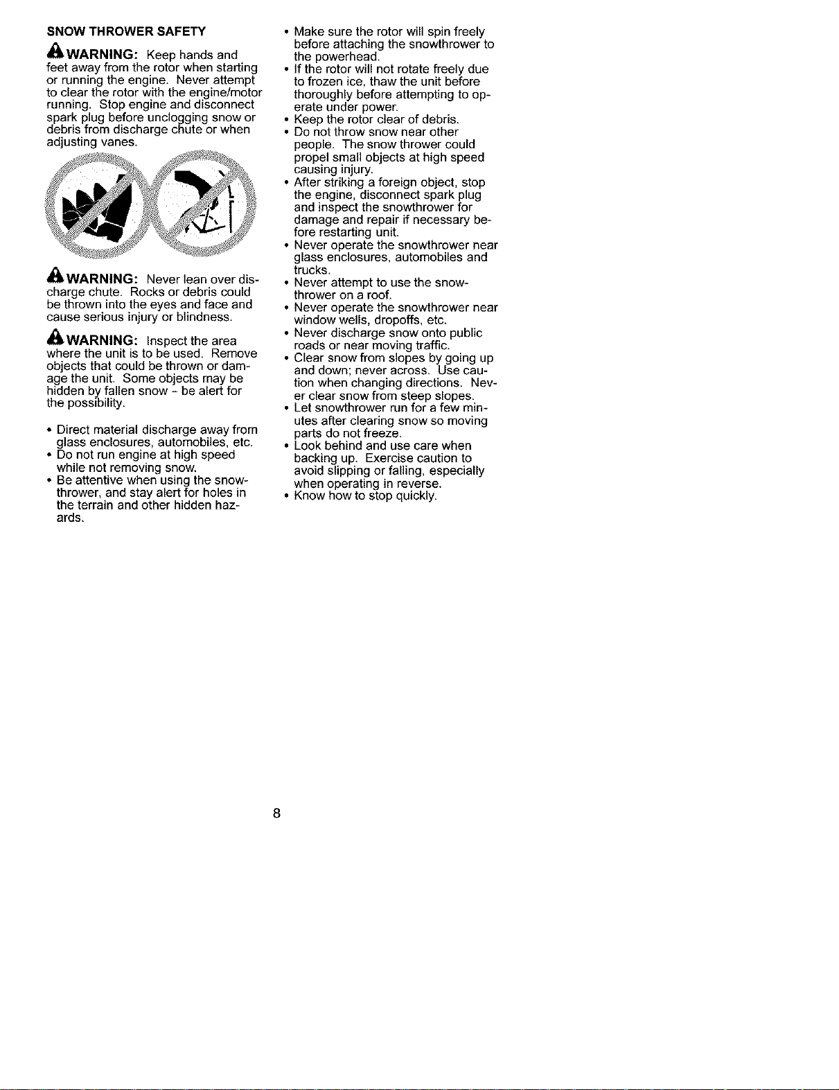
SNOW THROWER SAFETY
_Ib,WARNING: Keep hands and
feet away from the rotor when starting
or running the engine. Never attempt
to clear the rotor with the engine/motor
running. Stop engine and disconnect
spark plug before unclogging snow or
debris from discharge chute or when
adjusting vanes.
_ WARNING: Never lean over dis-
charge chute. Rocks or debris could
be thrown into the eyes and face and
cause serious injury or blindness.
_ WARNING: Inspect the area
where the unit is to be used. Remove
objects that could be thrown or dam-
age the unit. Some objects may be
hidden by fallen snow - be alert for
the possibility.
• Direct material discharge away from
glass enclosures, automobiles, etc.
• Do not run engine at high speed
while not removing snow.
• Be attentive when using the snow-
thrower, and stay alert for holes in
the terrain and other hidden haz-
ards.
• Make sure the rotor will spin freely
before attaching the snowthrower to
the powerhead.
• If the rotor will not rotate freely due
to frozen ice, thaw the unit before
thoroughly before attempting to op-
erate under powen
• Keep the rotor clear of debris.
• Do not throw snow near other
people. The snow thrower could
propel small objects at high speed
causing injury.
• After striking a foreign object, stop
the engine, disconnect spark plug
and inspect the snowthrower for
damage and repair if necessary be-
fore restarting unit.
• Never operate the snowthrower near
glass enclosures, automobiles and
trucks.
• Never attempt to use the snow-
thrower on a roof.
• Never operate the snowthrower near
window wells, dropoffs, etc.
• Never discharge snow onto public
roads or near moving traffic.
• Clear snow from slopes by going up
and down; never across. Use cau-
tion when changing directions. Nev-
er clear snow from steep slopes.
• Let snowthrower run for a few min-
utes after clearing snow so moving
parts do not freeze.
• Look behind and use care when
backing up. Exercise caution to
avoid slipping or falling, especially
when operating in reverse.
• Know how to stop quickly.
8
CARTON CONTENTS
Check carton contents against the fol-
lowing list.
Model 358.745191
• Powerhead
• Trimmer Attachment
• Shield
• Wing Nut (screwed onto shield)
• Container of Oil
Examine parts for damage. Do not
use damaged parts.
NOTE: If you need assistance or find
parts missing or damaged, call
1-800-235-5878.
It is normal for the fuel filter to rattle in
the empty fuel tank.
Finding fuel or oil residue on muffler is
normal due to carburetor adjustments
and testing done by the manufacturer.
ASSEMBLY
_ WARNING: If received as-
sembled, repeat all steps to ensure
your unit is properly assembled and all
fasteners are secure.
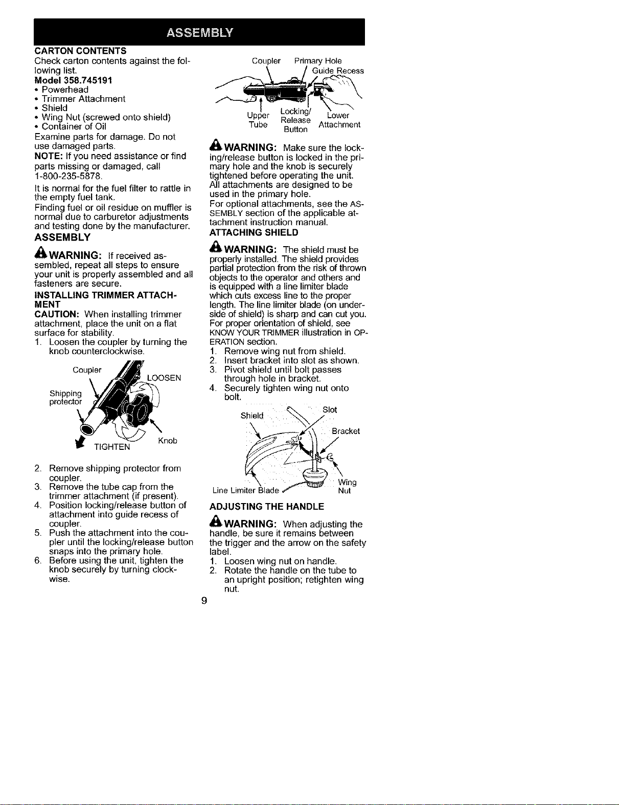
INSTALLING TRIMMER ATTACH-
MENT
CAUTION: When installing trimmer
attachment, place the unit on a flat
surface for stability.
1. Loosen the coupler by turning the
knob counterclockwise.
LOOSEN
Shipping
protector
Knob
TIGHTEN
2. Remove shipping protector from
coupler.
3. Remove the tube cap from the
trimmer attachment (if present).
4. Position locking/release button of
attachment into guide recess of
coupler.
5. Push the attachment into the cou-
pler until the locking/release button
snaps into the primary hole.
6. Before using the unit, tighten the
knob securely by turning clock-
wise.
Coupler Primary Hole
\ / Guide Recess
Upper Locking/ Lower
Tube Release Attachment
Button
_WARNING: Make sure the lock-
ing/release button is locked in the pri-
mary hole and the knob is securely
tightened before operating the unit.
All attachments are designed to be
used in the primary hole.
For optional attachments, see the AS-
SEMBLY section of the applicable at-
tachment instruction manual.
ATTACHING SHIELD
_WARNING: The shield must be
properly installed. The shield provides
partial protection from the risk of thrown
objects to the operator and others and
_sequipped with a line limiter blade
which cuts excess line to the proper
length. The line limiter blade (on under-
side of shield) is sharp and can cut you.
For proper orientation of shield, see
KNOWYOURTRIMMER illustration in OP-
ERATIONsection.
1. Remove wing nut from shield.
2. Insert bracket into slot as shown.
3. Pivot shield until bolt passes
through hole in bracket.
4. Securely tighten wing nut onto
bolt.
Slot
Shield _S
"k f\\ Bracket
Eng
Line Limiter Blade Nut
ADJUSTING THE HANDLE
,_WARNING: When adjusting the
handle, be sure it remains between
the trigger and the arrow on the safety
label,
1. Loosen wing nut on handle.
2. Rotate the handle on the tube to
an upright position; retighten wing
nut.
9
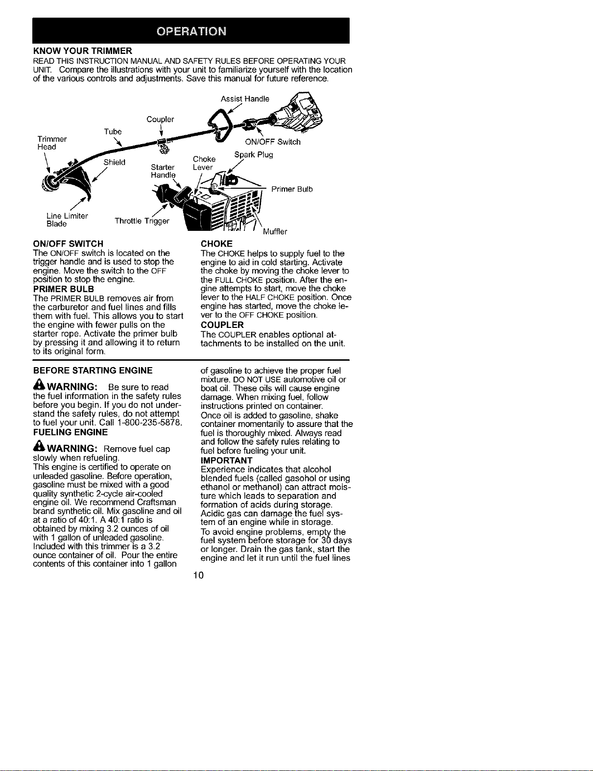
KNOW YOUR TRIMMER
READTHIS INSTRUCTIONMANUALANDSAFETY RULES BEFOREOPERATINGYOUR
UNIT. Compare the illustrations with your unit to familiarize yourself with the location
of the various controls and adjustments. Save this manual for future reference.
Assist Handle
Coupler
Tube
Trimmer ",& ON/OFF Switch
Head
ark Plug
Shield
/
Primer Bulb
Line Limiter
Blade Throttle Tngger
ON/OFF SWITCH
The ON/OFF switch is located on the
trigger handle and is used to stop the
engine, Move the switch to the OFF
position to stop the engine.
PRIMER BULB
The PRIMER BULB removes air from
the carburetor and fuel lines and fills
them with fuel. This allows you to start
the engine with fewer pulls on the
starter rope, Activate the primer bulb
by pressing it and allowing it to return
to its original form,
Muffler
CHOKE
The CHOKE helps to supply fuel to the
engine to aid in cold starting. Activate
the choke by moving the choke lever to
the FULLCHOKE position. After the en-
gine attempts to start, move the choke
lever to the HALFCHOKE position. Once
engine has started, move the choke le-
ver to the OFF CHOKEposition.
COUPLER
The COUPLER enables optional at-
tachments to be installed on the unit.
BEFORE STARTING ENGINE
_I, WARNING: Be sure to read
the fuel information in the safety rules
before you begin, If you do not under-
stand the safety rules, do not attempt
to fuel your unit, Call 1-800-235-5878,
FUELING ENGINE
_b, WARNING: Remove fuel cap
slowly when refueling,
This engine is certified to operate on
unleaded gasoline, Before operation,
gasoline must be mixed with a good
quality synthetic 2-cycle air-cooled
engine oil,We recommend Craftsman
brand synthetic oil, Mix gasoline and oil
at a ratio of 40:1, A 40:1 ratio is
obtained by mixing 3,2 ounces of oil
with 1 gallon of unleaded gasoline,
Included with this trimmer is a 3,2
ounce container of oil, Pour the entire
contents of this container into 1 gallon
of gasoline to achieve the proper fuel
mixture. DO NOTUSE automotive oil or
boat oil. These oils will cause engine
damage. When mixing fuel, follow
instructions printed on container.
Once oil is added to gasoline, shake
container momentarily to assure that the
fuel is thoroughly mixed. Always read
and follow the safety rules relating to
fuel before fueling your unit.
IMPORTANT
Experience indicates that alcohol
blended fuels (called gasohol or using
ethanol or methanol) can attract mois-
ture which leads to separation and
formation of acids during storage.
Acidic gas can damage the fuel sys-
tem of an engine while in storage.
To avoid engine problems, empty the
fuel systembefore storage for 30 days
or longer. Drain the gas tank, start the
engine and let it run until the fuel lines
10
and carburetor are empty. Use fresh
fuel next season.
Never use engine or carburetor clean-
er products in the fuel tank or perma-
nent damage may occur.
See the STORAGE section for addition-
al information.
HOW TO STOP YOUR UNIT
• To stop the engine, move the
ON/OFF switch to the OFF position.
• If engine does not stop, move choke
lever to FULL CHOKE position.
ON/OFF
Throttle Trigger _
\
HOW TO START YOUR UNIT
_ WARNING: The trimmer head
will turn while starting the engine.
Avoid any contact with the muffler. A
hot muffler can cause serious burns.
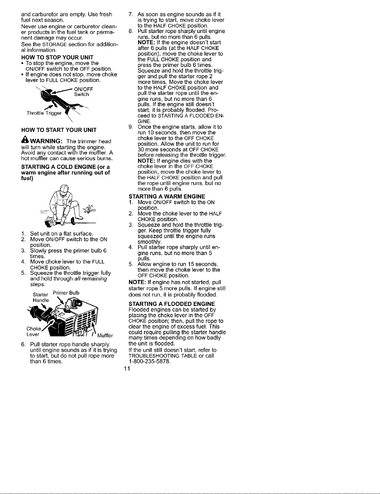
STARTING A COLD ENGINE (or a
warm engine after running out of
fuel)
1. Set unit on a flat surface.
2. Move ON/OFF switch to the ON
position.
3. Slowly press the primer bulb 6
times.
4. Move choke lever to the FULL
CHOKE position.
5. Squeeze the throttle trigger fully
and hold through all remaining
steps.
Starter Primer Bulb
Handle
Choke
Lever Mumer
6. Pull starter rope handle sharply
until engine sounds as if it is trying
to start, but do not pull rope more
than 6 times.
7. As soon as engine sounds as if it
is trying to start, move choke lever
to the HALF CHOKE position.
8. Pull starter rope sharply until engine
runs, but no more than 6 pulls.
NOTE: If the engine doesn't start
after 6 pulls (at the HALF CHOKE
position), move the choke lever to
the FULL CHOKE position and
press the primer bulb 6 times.
Squeeze and hold the throttle trig-
ger and pull the starter rope 2
more times. Move the choke lever
to the HALF CHOKE position and
pull the starter rope until the en-
gine runs, but no more than 6
pulls. If the engine still doesn't
start, it is probably flooded. Pro-
ceed to STARTING A FLOODED EN-
GINE.
9. Once the engine starts, allow it to
run 10 seconds, then move the
choke lever to the OFF CHOKE
position. Allow the unit to run for
30 more seconds at OFF CHOKE
before releasing the throttle trigger.
NOTE: If engine dies with the
choke lever in the OFF CHOKE
position, move the choke lever to
the HALF CHOKE position and pull
the rope until engine runs, but no
more than 6 pulls.
STARTING A WARM ENGINE
1. Move ON/OFF switch to the ON
position.
2. Move the choke lever to the HALF
CHOKE position.
3. Squeeze and hold the throttle trig-
ger. Keep throttle trigger fully
squeezed until the engine runs
smoothly.
4. Pull starter rope sharply until en-
gine runs, but no more than 5
pulls.
5. Allow engine to run 15 seconds,
then move the choke lever to the
OFF CHOKE position.
NOTE: If engine has not started, pull
starter rope 5 more pulls. If engine still
does not run, it is probably flooded.
STARTING A FLOODED ENGINE
Flooded engines can be started by
placing the choke lever in the OFF
CHOKE position; then, pull the rope to
clear the engine of excess fuel. This
could require pulling the starter handle
many times depending on how badly
the unit is flooded.
If the unit still doesn't start, refer to
TROUBLESHOOTING TABLE or call
1-800-235-5878.
11
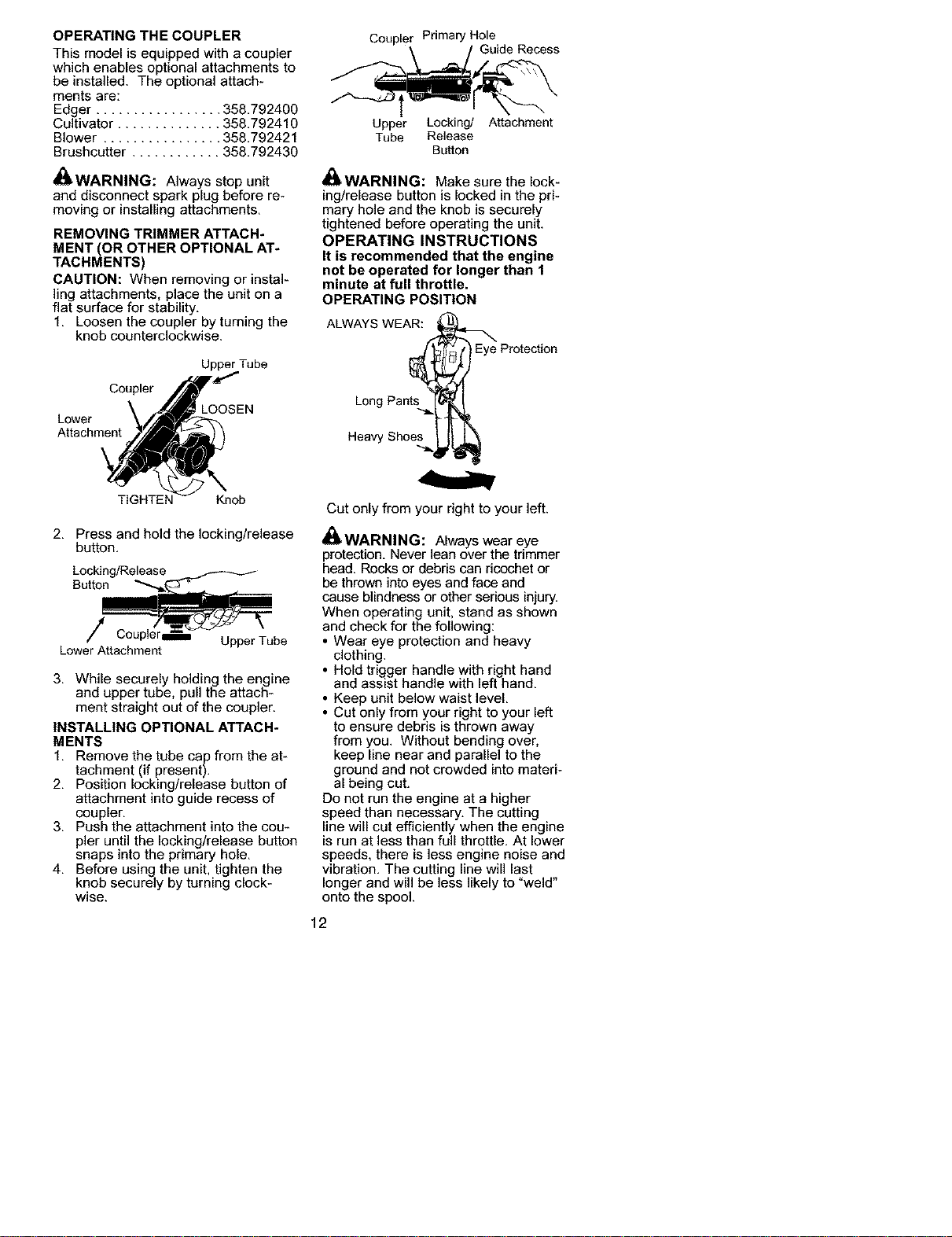
OPERATING THE COUPLER
This model is equipped with a coupler
which enables optional attachments to
be installed. The optional attach-
ments are:
Edger ................. 358.792400
Cultivator .............. 358.792410
Blower ................ 358.792421
Brushcutter ............ 358.792430
_WARNING: Always stop unit
and disconnect spark plug before re-
moving or installing attachments,
REMOVING TRIMMER ATTACH*
MENT (OR OTHER OPTIONAL AT*
TACHMENTS)
CAUTION: When removing or instal-
ling attachments, place the unit on a
flat surface for stability.
1. Loosen the coupler by turning the
knob counterclockwise.
Upper Tube
Coupler
i LOOSEN
Lower
Attachment
Coupler Primary Hole
Upper Locking/ Attachment
Tube Release
Button
_WARNING: Make sure the lock-
ing/release button is locked in the pri-
mary hole and the knob is securely
tightened before operating the unit.
OPERATING INSTRUCTIONS
It is recommended that the engine
not be operated for longer than 1
minute at full throttle.
OPERATING POSITION
ALWAYS WEAR:_
Long Pan_ Eye Protection
Heavy Sho_
TIGHTEN Knob
2, Press and hold the locking/release
button,
Locking/Release
Button
/
LowerAttachment
UpperTube
3. While securely holding the engine
and upper tube, pull the attach-
ment straight out of the coupler.
INSTALLING OPTIONAL ATTACH*
MENTS
1. Remove the tube cap from the at-
tachment (if present).
2. Position locking/release button of
attachment into guide recess of
coupler.
3. Push the attachment into the cou-
pler until the locking/release button
snaps into the primary hole.
4. Before using the unit, tighten the
knob securely by turning clock-
wise.
Cut only from your right to your left.
Z_
d_,WARNING: Always wear eye
protection. Never lean over the trimmer
head. Rocks or debris can ricochet or
be thrown into eyes and face and
cause blindness or other serious injury.
When operating unit, stand as shown
and check for the following:
• Wear eye protection and heavy
clothing.
• Hold trigger handle with right hand
and assist handle with left hand.
• Keep unit below waist level.
• Cut only from your right to your left
to ensure debris is thrown away
from you. Without bending over,
keep line near and parallel to the
ground and not crowded into materi-
al being cut.
Do not run the engine at a higher
speed than necessary. The cutting
line will cut efficiently when the engine
is run at less than full throttle. At lower
speeds, there is less engine noise and
vibration. The cutting line will last ,,
longer and will be less likely to "weld
onto the spool.
12
Always release the throttle trigger and
allow the engine to return to idle
speed when not cutting.
To stop engine:
* Release the throttle trigger.
* Move the ON/OFF switch to the OFF
position,
TRIMMER LINE ADVANCE
The cutting head advances line au-
tomatically. Do not tap head on the
ground to advance line. This may
break parts and cause cutting head to
malfunction,
Upon unit start up, the line will ad-
vance automatically to the correct cut-
ting path length.
Always keep the shield in place when
the tool is being operated.
WARNING: Use only 0.080"
(2 mm) diameter round line. Other
sizes and shapes of line will not ad-
vance properly and will result in im-
proper cutting head function or can
cause serious in ury. Do not use other
mater a s such as w re, str ng, rope,
etc. Wire can break off during cutting
and become a dangerous missile that
can cause serious injury.
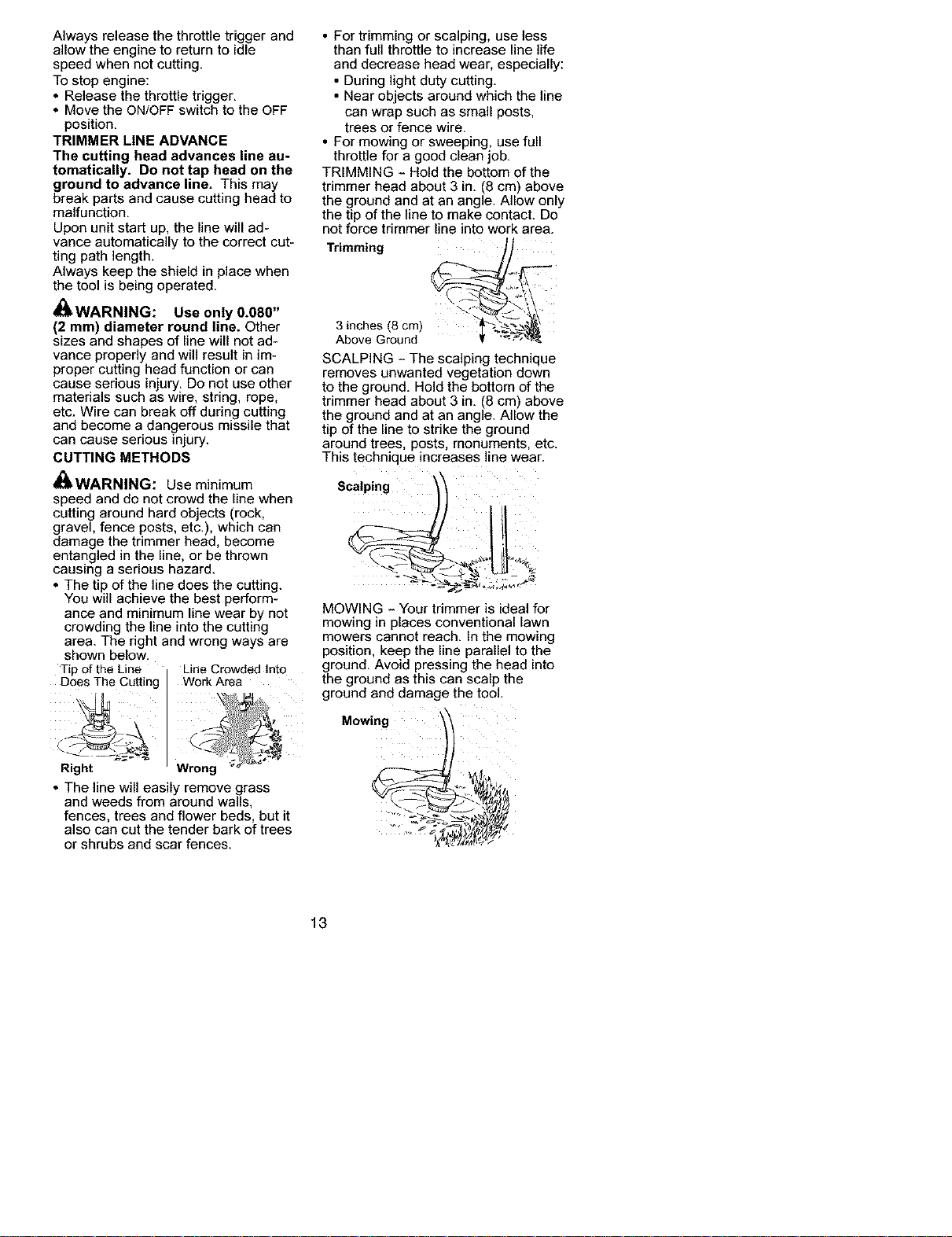
CUTTING METHODS
_WARNING: Use minimum
• For trimming or scalping, use less
than full throttle to increase line life
and decrease head wear, especially:
• During light duty cutting.
• Near objects around which the line
can wrap such as small posts,
trees or fence wire.
• For mowing or sweeping, use full
throttle for a good clean job.
TRIMMING - Hold the bottom of the
trimmer head about 3 in. (8 cm) above
the ground and at an angle. Allow only
the tip of the line to make contact. Do
not force trimmer line into work area.
Trimming _ "t__"-_
3 inches(8 cm)
Above Ground
SCALPING - The scalping technique
removes unwanted vegetation down
to the ground. Hold the bottom of the
trimmer head about 3 in. (8 cm) above
the ground and at an angle. Allow the
tip of the line to strike the ground
around trees, posts, monuments, etc.
This technique increases line wear.
Scalping
speed and do not crowd the line when
cutting around hard objects (rock, _-'__'lt "_
gravel, fence posts, etc.), which can
damage the trimmer head, become
entangled in the line, or be thrown
causing a serious hazard. "
* The tip of the line does the cutting. _-_-'_•.,_" i__._,,_--
You will achieve the best perform-
ance and minimum line wear by not
crowding the line into the cutting
area. The right and wrong ways are
shown below.
Tip of the Line I Line Crowded into
_S The Cutting Work Area
Right ' Wrong _'-_
. The line will easily remove grass
and weeds from around walls,
fences, trees and flower beds, but it
also can cut the tender bark of trees
or shrubs and scar fences.
MOWING - Your trimmer is ideal for
mowing in places conventional lawn
mowers cannot reach. In the mowing
position, keep the line parallel to the
ground. Avoid pressing the head into
the ground as this can scalp the
ground and damage the tool.
Mowing
13
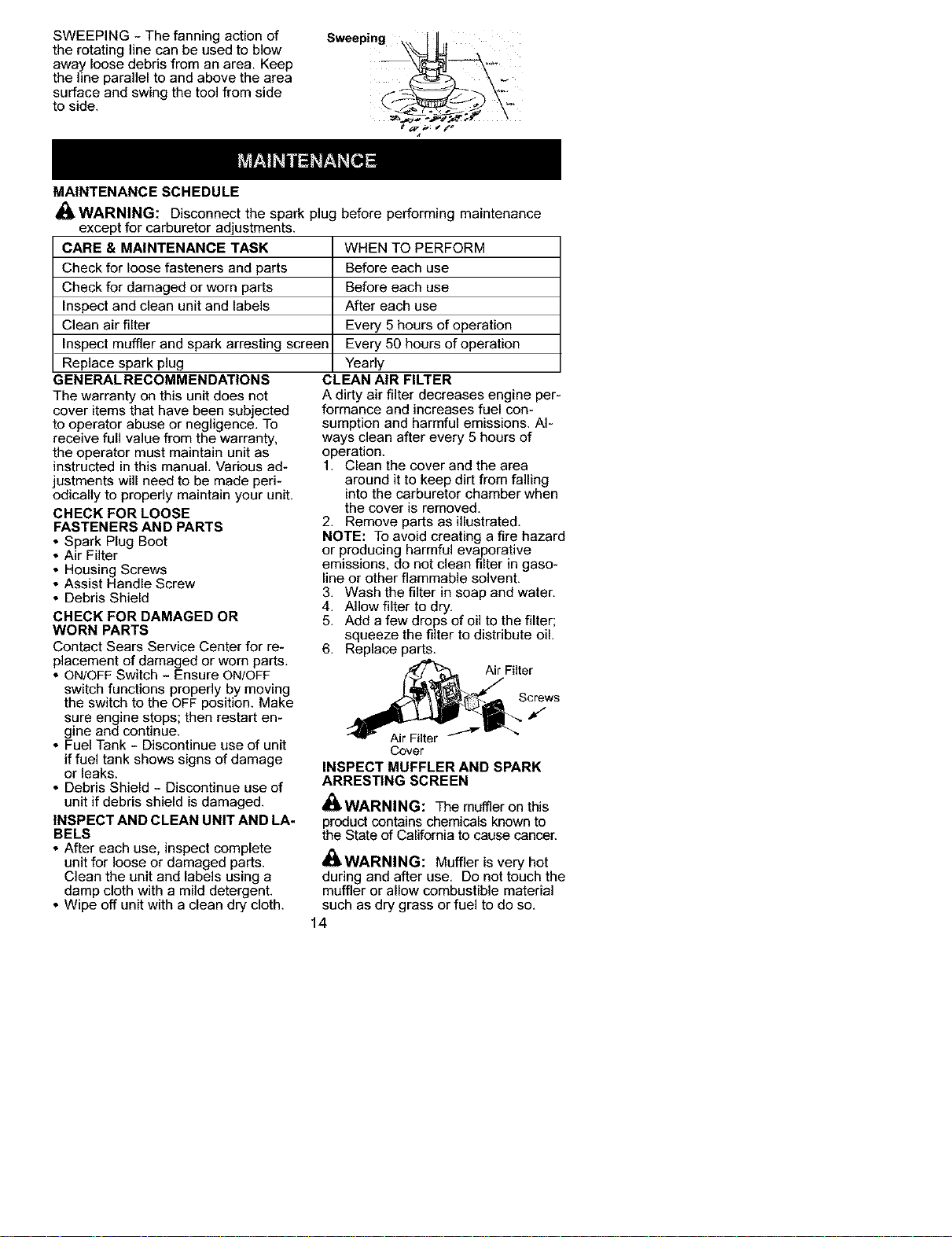
SWEEPING - The fanning action of
the rotating line can be used to blow
away loose debris from an area, Keep
the line parallel to and above the area
surface and swing the tool from side
to side.
Sweeping \_ IIIt
MAINTENANCE SCHEDULE
WARNING: Disconnect the spark plug before performing maintenance
except for carburetor adjustments.
CARE & MAINTENANCE TASK
Check for loose fasteners and parts
Check for damaged or worn parts
Inspect and clean unit and labels
Clean air filter
Inspect muffler and spark arresting screen
Replace spark plug
_ENERAL RECOMMENDATIONS
The warranty on this unit does not
cover items that have been sub ected
to operator abuse or neg gence. To
receive full value from the warranty,
the operator must maintain unit as
instructed in this manual. Various ad-
justments will need to be made peri-
odically to properly maintain your unit.
CHECK FOR LOOSE
WHEN TO PERFORM
Before each use
Before each use
After each use
Every 5 hours of operation
Every 50 hours of operation
Yearly
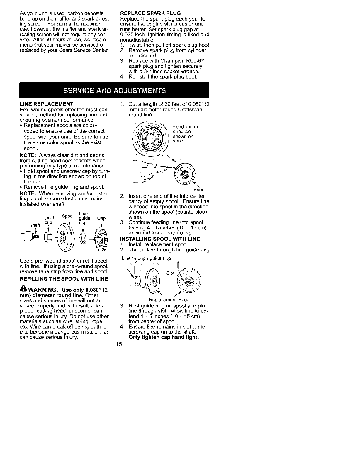
:LEAN AIR FILTER
A dirty air filter decreases engine per-
formance and increases fuel con-
sumption and harmful emissions. Al-
ways clean after every 5 hours of
operation.
1. Clean the cover and the area
around it to keep dirt from falling
into the carburetor chamber when
the cover is removed.
FASTENERS AND PARTS
, Spark Plug Boot
* Air Filter
* Housing Screws
* Assist Handle Screw
* Debris Shield
CHECK FOR DAMAGED OR
WORN PARTS
2. Remove parts as illustrated.
NOTE: To avoid creating a fire hazard
or producing harmful evaporative
emissions, do not clean filter in gaso-
line or other flammable solvent.
3. Wash the filter in soap and water.
4. Allow filter to dry.
5. Add a few drops of oil to the filter;
squeeze the filter to distribute oil
Contact Sears Service Center for re-
placement of damaged or worn parts.
* ON/OFF Switch - Ensure ON/OFF
switch functions properly by moving
the switch to the OFF position. Make
sure engine stops; then restart en-
gine and continue.
* Fuel Tank - Discontinue use of unit
if fuel tank shows signs of damage
or leaks.
* Debris Shield - Discontinue use of
unit if debris shield is damaged.
INSPECT AND CLEAN UNIT AND LA-
BELS
* After each use, inspect complete
unit for loose or damaged parts.
Clean the unit and labels using a
damp cloth with a mild detergent.
* Wipe off unit with a clean dry cloth.
6. Replace parts.
_Filtse _rews
Cover
INSPECT MUFFLER AND SPARK
ARRESTING SCREEN
_ WARNING: The muffler on this
product contains chemicals known to
the State of California to cause cancer.
&WARNING: Muffler is very hot
during and after use, Do not touch the
muffler or allow combustible material
such as dry grass or fuel to do so,
14
As your unit is used, carbon deposits
build up on the muffler and spark arrest-
ing screen. For normal homeowner
use, however, the muffler and spark ar-
resting screen will not require any ser-
vice. After 50 hours of use, we recom-
mend that your muffler be serviced or
replaced by your Sears Service Center.
REPLACE SPARK PLUG
Replace the spark plug each year to
ensure the engine starts easier and
runs better. Set spark plug gap at
0.025 inch. Ignition timing is fixed and
nonad ustable.
1. Twst, then pu off spark plug boot.
2. Remove spark plug from cylinder
and discard.
3. Replace with Champion RCJ-6Y
spark plug and tighten securely
with a 3/4 inch socket wrench.
4. Reinstall the spark plug boot.
LINE REPLACEMENT
Pre-wound spools offer the most con-
venient method for replacing line and
ensuring optimum performance.
* Replacement spools are color-
coded to ensure use of the correct
spool with your unit. Be sure to use
the same color spool as the existing
spool.
NOTE: Always clear dirt and debris
from cutting head components when
performing any type of maintenance.
* Hold spool and unscrew cap by turn-
ing in the direction shown on top of
the cap.
* Remove line guide ring and spool.
NOTE: When removing and/or instal-
ling spool, ensure dust cup remains
installed over shaft.
Dust Spool L_ e Cap
___ cup ._.I' ring j,
Use a pre-wound spool or refill spool
with line. If using a pre-wound spool,
remove tape strip from line and spool.
REFILLING THE SPOOL WITH LINE
_WARNING: Use only 0.080" (2
mm) diameter round line. Other
sizes and shapes of line will not ad-
vance properly and will result in im-
proper cutting head function or can
cause serious in ury, Do not use other
mater a s such as w re, str ng, rope,
etc. Wire can break off during cutting
and become a dangerous missile that
can cause serious injury.
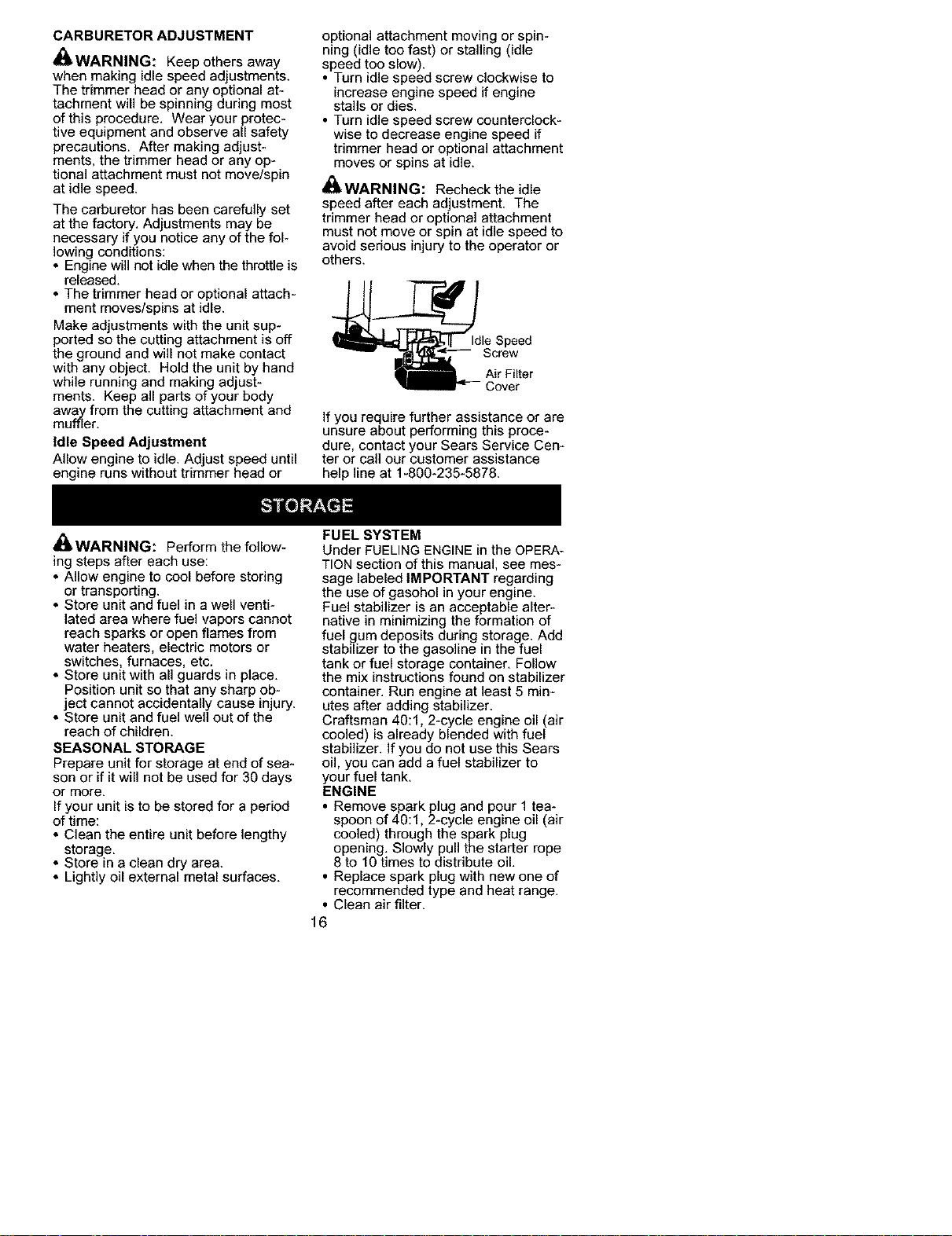
1. Cut a length of 30 feet of 0.080" (2
ram) diameter round Craftsman
brand line.
_ eedtiline in
S_o_n on
Spool
2. insert one end of line into center
cavity of empty spool. Ensure line
will feed into spool in the direction
shown on the spool (counterclock-
wise).
3. Continue feeding line into spool,
leaving 4 - 6 inches (10 - 15 cm)
unwound from center of spool.
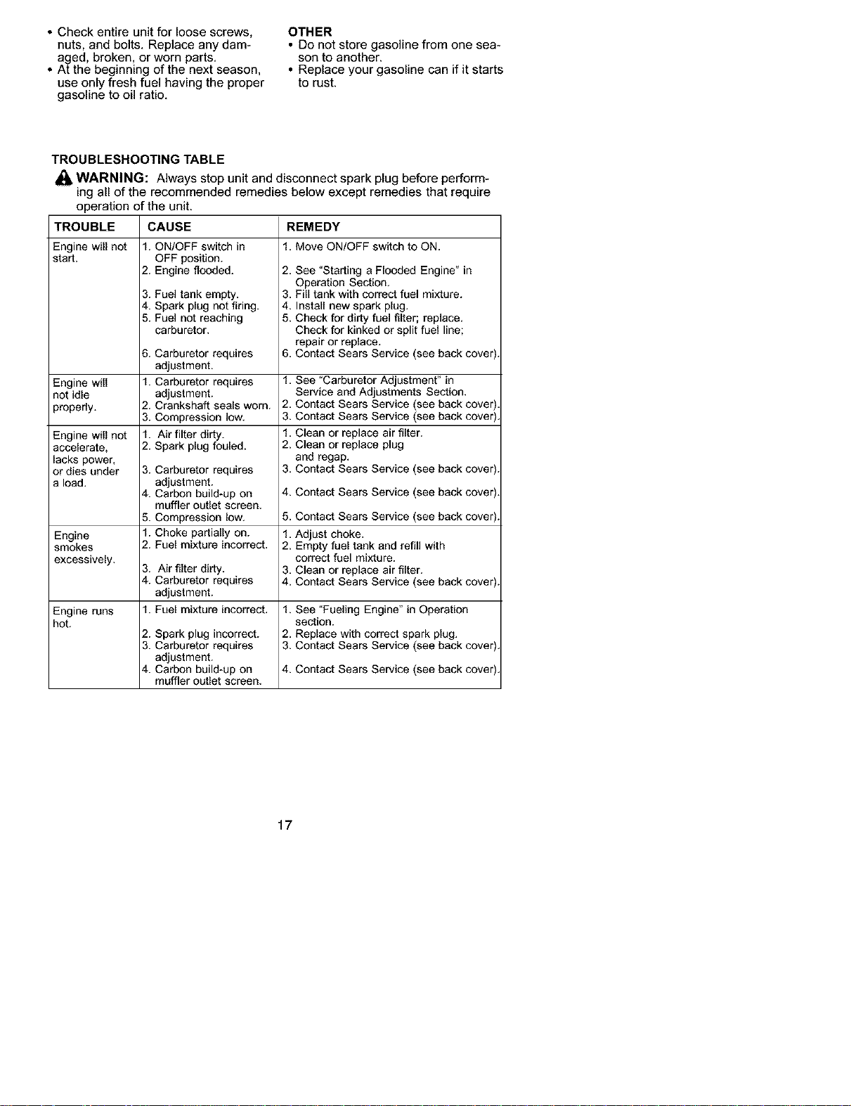
INSTALLING SPOOL WITH LINE
1. Install replacement spool.
2. Thread line through line guide ring.
Line through guide ring #
Replacement Spool
3. Rest guide ring on spool and place
line through slot. Allow line to ex-
tend 4 - 6 inches (10 - 15 cm)
from center of spool.
4. Ensure line remains in slot while
screwing cap on to the shaft.
Only tighten cap hand tightI
15
CARBURETOR ADJUSTMENT
_ WARNING: Keep others away
when making idle speed adjustments.
The trimmer head or any optional at-
tachment will be spinning during most
of this procedure. Wear your protec-
tive equipment and observe all safety
precautions. After making adjust-
ments, the trimmer head or any op-
tional attachment must not move/spin
at idle speed.
The carburetor has been carefully set
at the factory. Adjustments may be
necessary if you notice any of the fol-
lowing conditions:
• Engine will not idlewhen the throttle is
released.
• The trimmer head or optional attach-
ment moves/spins at idle.
Make adjustments with the unit sup-
ported so the cutting attachment is off
the ground and will not make contact
with any object. Hold the unit by hand
while running and making adjust-
ments. Keep all parts of your body
away from the cutting attachment and
muffler.
Idle Speed Adjustment
Allow engine to idle. Adjust speed until
engine runs without trimmer head or
optional attachment moving or spin-
ning (idle too fast) or stalling (idle
speed too slow).
Turn idle speed screw clockwise to
increase engine speed if engine
stalls or dies.
• Turn idle speed screw counterclock-
wise to decrease engine speed if
trimmer head or optional attachment
moves or spins at idle.
_ WARNING: Recheck the idle
speed after each adjustment, The
trimmer head or optional attachment
must not move or spin at idle speed to
avoid serious injury to the operator or
others.
_dle Speed
Screw
Air Filter
_- Cover
If you require further assistance or are
unsure about performing this proce-
dure, contact your Sears Service Cen-
ter or call our customer assistance
help line at 1-800-235-5878.
_ WARNING: Perform the follow-
ing steps after each use:
• Allow engine to cool before storing
or transporting.
• Store unit and fuel in a well venti-
lated area where fuel vapors cannot
reach sparks or open flames from
water heaters, electric motors or
switches, furnaces, etc.
• Store unit with all guards in place.
Position unit so that any sharp ob-
ject cannot accidentally cause injury.
• Store unit and fuel well out of the
reach of children.
SEASONAL STORAGE
Prepare unit for storage at end of sea-
son or if it will not be used for 30 days
or more.
If your unit is to be stored for a period
of time:
• Clean the entire unit before lengthy
storage.
• Store in a clean dry area.
• Lightly oil external metal surfaces.
FUEL SYSTEM
Under FUELING ENGINE in the OPERA-
TION section of this manual, see mes-
sage labeled IMPORTANT regarding
the use of gasohol in your engine.
Fuel stabilizer is an acceptable alter-
native in minimizing the formation of
fuel gum deposits during storage. Add
stabilizer to the gasoline in the fuel
tank or fuel storage container. Follow
the mix instructions found on stabilizer
container. Run engine at least 5 min-
utes after adding stabilizer.
Craftsman 40:1, 2-cycle engine oil (air
cooled) is already blended with fuel
stabilizer, if you do not use this Sears
oil, you can add a fuel stabilizer to
your fuel tank.
ENGINE
• Remove spark plug and pour 1 tea-
spoon of 40:1, 2-cycle engine oil (air
cooled) through the spark plug
opening. Slowly pull the starter rope
8 to 10 times to distribute oil.
• Replace spark plug with new one of
recommended type and heat range.
• Clean air filter.
16
• Check entire unit for loose screws,
nuts, and bolts. Replace any dam-
aged, broken, or worn parts.
• At the beginning of the next season,
use only fresh fuel having the proper
gasoline to oil ratio.
OTHER
• Do not store gasoline from one sea-
son to another.
• Replace your gasoline can if it starts
to rust.
TROUBLESHOOTING TABLE
WARNING: Always stop unit and disconnect spark plug before perform-
ing all of the recommended remedies below except remedies that require
operation of the unit.
TROUBLE
Engine will not
start.
Engine will
not idle
properly.
Engine will not
accelerate,
lacks power,
or dies under
a load.
Engine
smokes
excessively,
Engine runs
hot,
CAUSE REMEDY
f. MoveON/OFFswitchtoON.1. ON/OFF switch in
OFF position.
2. Engine flooded.
3. Fuel tank empty.
4. Spark plug not firing.
5. Fuel not reaching
carburetor,
6. Carburetor requires
adjustment.
1. Carburetor requires
adjustment.
2. Crankshaft seals worn.
3. Compression low,
1. Air filter dirty.
2. Spark plug fouled.
3. Carburetor requires
adjustment.
4. Carbon build-up on
muffler outlet screen.
5. Compression low.
1. Choke partially on.
2. Fuel mixture incorrect.
3. Air filter dirty,
4. Carburetor requires
adjustment.
1. Fuel mixture incorrect,
2. Spark plug incorrect.
3. Carburetor requires
adjustment.
4. Carbon build-up on
muffler outlet screen,
2. See "Starting a Flooded Engine" in
Operation Section,
3. Fill tank with correct fuel mixture.
4. Install new spark plug.
5. Check for dirty fuel filter; replace,
Check for kinked or split fuel line;
repair or replace.
6. Contact Sears Service (see back cover)
1. See "Carburetor Adjustment" in
Service and Adjustments Section.
2. Contact Sears Service (see back cover)
3. Contact Sears Service (see back cover)
1. Clean or replace air filter.
2. Clean or replace plug
and regap,
3. Contact Sears Service (see back cover)
4. Contact Sears Service (see back cover)
5. Contact Sears Service (see back cover)
1. Adjust choke.
2. Empty fuel tank and refill with
correct fuel mixture.
3. Clean or replace air filter.
4. Contact Sears Service (see back cover)
1. See "Fueling Engine" in Operation
section.
2. Replace with correct spark plug.
3. Contact Sears Service (see back cover)
4. Contact Sears Service (see back cover)
17

YOUR WARRANTY RIGHTS AND
OBLIGATIONS: The U.S. Environ-
mental Protection Agency/California
Air Resources Board and Sears, Roe-
buck and Co., U.S.A., are pleased to
explain the emissions control system
warranty on your year 2002-2004
small off-road engine. In California, all
new small off-road engines must be
designed, built, and equipped to meet
the State's stringent anti-smog stan-
dards. Sears must warrant the emis-
sion control system on your small off-
road engine for the periods of time
listed below provided there has been
no abuse, neglect, or improper main-
tenance of your small off-road engine
engine. Your emission control system
includes parts such as the carburetor
and the ignition system. Where a war-
rantable condition exists, Sears will
repair your small off-road engine en-
gine at no cost to you. Expenses cov-
ered under warranty include diagno-
sis, parts and labor.
MANUFACTURER'S WARRANTY
COVERAGE: If any emissions related
part on your engine (as listed under
Emissions Control Warranty Parts
List) is defective or a defect in the ma-
terials or workmanship of the engine
causes the failure of such an emission
related part, the part will be repaired or
replaced by Sears. OWNER'S WAR-
RANTY RESPONSIBILITIES: As the
small off-road engine engine owner,
you are responsible for the perfor-
mance of the required maintenance
listed in your instruction manual.
Sears recommends that you retain all
receipts covering maintenance on
your small off-road engine, but Sears
cannot deny warranty solely for the
lack of receipts or for your failure to
ensure the performance of all sched-
uled maintenance. As the small off-
road engine engine owner, you should
be aware that Sears may deny you
warranty coverage if your small off-
road engine engine or a part of it has
failed due to abuse, neglect, improper
maintenance, unapproved modifica-
tions, or the use of parts not made or
approved by the original equipment
manufacturer. You are responsible for
presenting your small off-road engine
to a Sears authorized repair center as
soon as a problem exists. Warranty
repairs should be completed in area*
sonable amount of time, not to exceed
30 days. If you have any questions
regarding your warranty rights and re-
sponsibilities, you should contact your
nearest authorized service center or
call Sears at 1-800-469-4663. WAR-
RANTY COMMENCEMENT DATE:
The warranty period begins on the
date the small off-road engine is pur-
chased. LENGTH OF COVERAGE:
This warranty shall be for a period of
two years from the initial date of pur-
chase. WHAT IS COVERED: RE-
PAIR OR REPLACEMENT OF
PARTS. Repair or replacement of any
warranted part will be performed at no
charge to the owner at an approved
Sears Service Center. If you have any
questions regarding your warranty
rights and responsibilities, you should
contact your nearest authorized ser-
vice center or call Sears at
1-800-469-4663. WARRANTY PE-
RIOD: Any warranted part which is not
scheduled for replacement as re-
quired maintenance, or which is
scheduled only for regular inspection
to the effect of"repair or replace as
necessary" shall be warranted for 2
years. Any warranted part which is
scheduled for replacement as re-
quired maintenance shall be war-
ranted for the period of time up to the
first scheduled replacement point for
that part. DIAGNOSIS: The owner
shall not be charged for diagnostic la-
bor which leads to the determination
that a warranted part is defective if the
diagnostic work is performed at an ap-
proved Sears Service Center. CON*
SEQUENTIAL DAMAGES: Sears
may be liable for damages to other
engine components caused by the
failure of a warranted part still under
warranty. WHAT IS NOT COVERED:
All failures caused by abuse, neglect,
or improper maintenance are not cov-
ered. ADD-ON OR MODIFIED
PARTS: The use of add-on or modi-
fied parts can be grounds for disallow-
ing a warranty claim. Sears is not li-
able to cover failures of warranted
parts caused by the use of add-on or
modified parts. HOW TO FILE A
CLAIM: If you have any questions re-
garding your warranty rights and re-
sponsibilities, you should contact your
18

nearestauthorizedservicecenteror
callSearsat1-800-4694663,
WHERE TO GET WARRANTY SER_
VICE: Warranty services or repairs
shall be provided at all Sears Service
Centers, Call 1-8004694663.
MAINTENANCE, REPLACEMENT
AND REPAIR OF EMISSION RE-
LATED PARTS: Any Sears approved
replacement part used in the perfor-
mance of any warranty maintenance
or repair on emission related parts will
be provided without charge to the
owner if the part is under warranty.
EMISSION CONTROL WARRANTY
PARTS LIST: Carburetor, Ignition Sys-
tem: Spark Plug (covered up to main-
tenance schedule). Ignition Module,
Muffler including catalyst. MAINTE-
NANCE STATEMENT: The owner is
responsible for the performance of all
required maintenance as defined in
the instruction manual.
This engine is certified to be emissions compliant for the following use:
[] Moderate (50 hours)
[] Intermediate (125 hours)
[] Extended (300 hours)
19