Loading ...
Loading ...
Loading ...
4
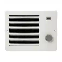
FIG. 9
FIG. 12
BLK
NEGRO
BLK
NEGRO
BLK
NEGRO
DISCONNECT FOR HALF-
WAT TAG E
DESCONECTE PARA
MEDIO VATIAJE
THERMAL
OVERLOAD
SOBRECARGA
TERMICA
BLK
NEGRO
BLK
NEGRO
THERMOSTAT
TERMOSTATO
WHT
BLANCO
WHT
BLANCO
WHT
BLANCO
BLK
NEGRO
BLK
NEGRO
BLK
NEGRO
BLK
NEGRO
BLK
NEGRO
M
WHT
BLANCO
WHT
BLANCO
WHT
BLANCO
WHT
BLANCO
THERMOSTAT
TERMOSTATO
THERMAL
OVERLOAD
SOBRECARGA
TERMICA
WHT
BLANCO
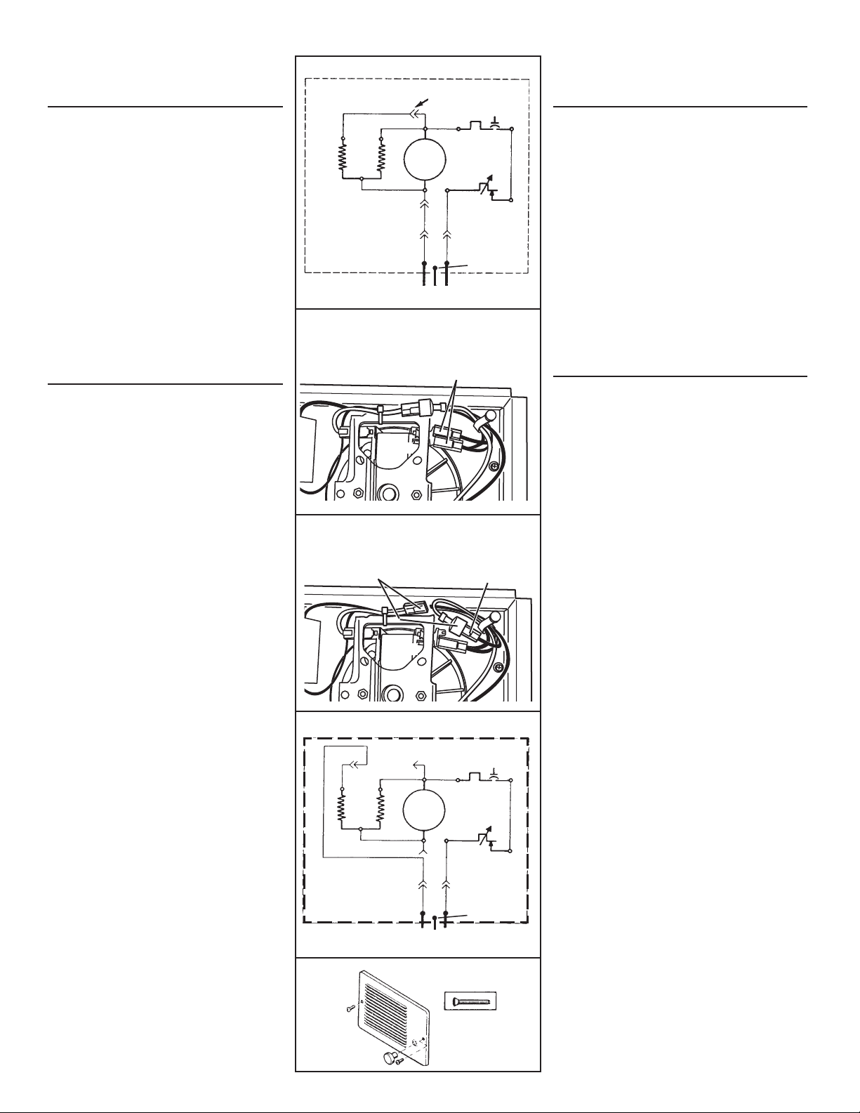
FIG. 13
HEATING
ELEMENT
ELEMENTO
DE CALOR
M
BLK
NEGRO
FACTORY-WIRED
HEATER (FULL
WATTAGE)
CALENTADOR
CABLEADO EN FABRICA
(VATIAJE COMPLETO)
LINE IN LINEA DE ENTRADA
HEATING
ELEMENT
ELEMENTO
DE CALOR
BLK
NEGRO
CONVERTED 240 VAC
HEATER
CALENTADOR 240
VCA CONVERTIDO
OPTIONAL WIRING
CONVERSIONS
1. Conversion to half-wattage. (FIGS. 9 & 10)
The heater will produce less heat and use less
electricity if converted to half-wattage.
Disconnect ONE of the two (2) black wires (with
insulated terminals) from the motor.
2. 120 VAC to 240 VAC Conversion (FIGS. 11 & 12)
(Factory-wired 120 VAC Models 170 and 174 ONLY)
These heaters can be converted to operate on
240 VAC.
1) Disconnect ONE of the two (2) black wires (with
insulated terminals) from the motor.
2) Disconnect the two (2) white wires (with insu-
lated terminals) from each other. Do not remove
the white wire from beneath plastic wire tie.
3) Connect the black wire to the white wire.
NOTE: When heater is converted from 120 VAC to
240 VAC, half-wattage conversion is not possible.
COMPLETE
INSTALLATION
(NEW CONSTRUCTION)
1. A housing mask has been provided to keep
construction dust, drywall spray, paint, etc.
from damaging heater.
Bend the flaps on the mask and push it into
the heater housing.
NOTE: Mask can be put in place before or
after heater assembly is re-installed.
2. Remove mask before operation.
(ALL INSTALLATIONS)
3. Secure heater assembly with retaining screw
and plug wiring harness into receptacle.
4. Fasten grille to heater with two (2) screws
provided. (FIG. 13)
5. Push knob onto thermostat stem.
6. Turn on power at service entrance. Turn
thermostat to its highest setting and make
sure heating element and blower come on.
Then make sure element and blower shut off
at lowest thermostat setting.
FIG. 10 - HALF-WATTAGE CONVERSION
CONVERSIÓN DE MEDIO VATIAJE
(2) BLACK WIRES (connected to motor)
(2) CABLES NEGROS (conectados al motor)
MOTOR
FIG. 11 - 120VAC TO 240VAC CONVERSION
CONVERSIÓN DE 120VCA A 240VCA
BLACK WIRE (from motor)
CABLE NEGRO (del motor)
WHITE WIRES
CABLES BLANCOS
MOTOR
CONVERSIONES DE
CABLEADO OPCIONAL
1. Conversión a mitad de vatiaje. (FIGS. 9 & 10)
El calentador producirá menos calor y usará menos
electricidad si se le convierte a mitad de vatiaje.
Desconecte UNO de los dos (2) alambres negros (con
los terminales aisladas) del motor.
2. Conversión de 120 VCA a 240 VCA. (FIGS. 11 & 12)
(SOLAMENTE Modelos 170 & 174 de 120 VCA
cableados en fábrica).
Estos calentadores se pueden convertir de modo que
puedan funcionar con 240 VCA.
1) Desconecte UNO de los dos (2) alambres negros
(con los terminales aisladas) del motor.
2) Desconecte los dos (2) alambres blancos (con
terminales aisladas). No quite el alambre blanco
de abajo del enlace del cable plástico.
3) Conecte el alambre negro al alambre blanco.
NOTA: Cuando el calentador se convierte de 120 VAC a
240 VAC, no es posible la conversión a mitad de vatiaje.
COMPLETE
LA INSTALACION
(NUEVA CONSTRUCCIÓN)
1. Se provee una cubierta de caja para evitar que el
polvo de la construcción, rocíos de yeso, pintura,
etc., dañen el calentador.
Doble las aletas de la cubierta y póngala dentro
de la caja del calentador.
NOTA: La cubierta se debe colocar en su lugar
antes o después de reinstalar el equipo del
calentador.
2. Quite la cubierta antes del funcionamiento.
(TODAS LAS INSTALACIONES)
3. Fije el conjunto del calentador con el tornillo de
retención y conecte el conjunto preconfigurado
de cables al enchufe.
4. Sujete la rejilla al calentador con los dos (2)
tornillos que se proveen. (FIG. 13)
5. Empuje la perilla en el vástago del termostato.
6. Conecte la potencia en la entrada de servicio.
Active el termostato en su graduación más alta y
compruebe que se activan el elemento de calor y
el soplador. Luego compruebe que el elemento
y el soplador se apaguen en la graduación de
termostato más baja.
GROUND
TIERRA
GROUND
TIERRA
240 VAC LINE IN
LINEA DE ENTRADA 240 VCA
Loading ...
Loading ...
Loading ...