Safety • Assembly • Operation • Tips & Techniques • Maintenance • Troubleshooting • Parts Lists • Warranty
OF A O AL
/
/
/
/
/
*ModelSeries460Shown
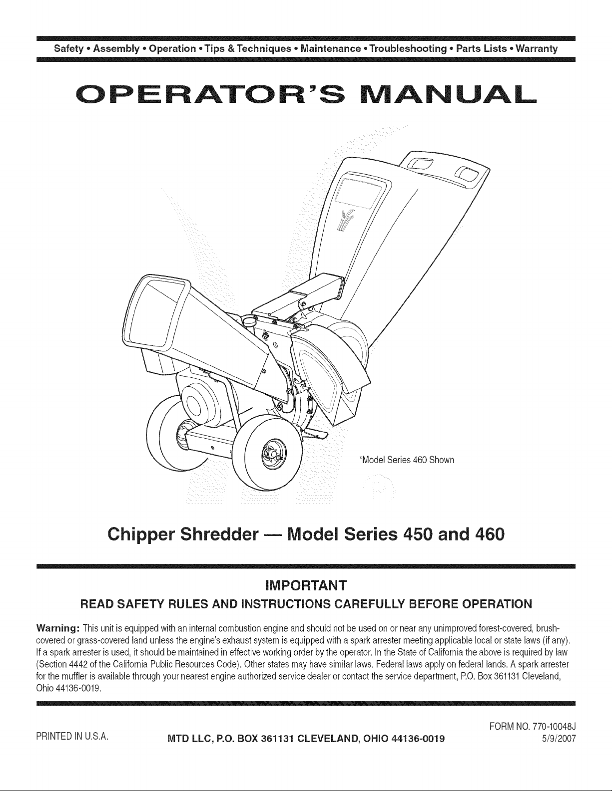
Chipper Shredder- Model Series 450 and 460
IMPORTANT
READ SAFETY RULES AND iNSTRUCTiONS CAREFULLY BEFORE OPERATION
Warning: Thisunit isequippedwithan internalcombustionengineandshouldnot beusedon or nearany unimprovedforest-covered,brush-
coveredor grass-coveredlandunlesstheengine'sexhaustsystemis equippedwitha sparkarrestermeetingapplicablelocalor statelaws(if any).
If a sparkarresterisused,it shouldbemaintainedineffectiveworkingorderby the operator.In theStateof Californiathe aboveisrequiredbylaw
(Section4442of the CaliforniaPublicResourcesCode).Otherstatesmayhavesimilarlaws.Federallaws applyon federallands.A sparkarrester
for the muffleris availablethroughyour nearestengineauthorizedservicedealeror contactthe servicedepartment,RO. Box361131Cleveland,
Ohio44136-0019.
PRINTEDIN U.S.A.
MTD LLC, P.O. BOX 361131 CLEVELAND, OHIO 44136-0019
FORMNO. 770-10048J
5/9/2007
This Operator's IVlanual is an important part of your new chipper shredder, it will help you assemble, pre-
pare and maintain the unit for best performance. Please read and understand what it says.
Table of Contents
Customer Support .............................................. 2
Safety Labels ...................................................... 3
Safe Operation Practices ................................... 4
Setting UpYour Chipper Shredder .................... 6
Operating Your Chipper Shredder ................... 10
Maintaining Your Chipper Shredder ................ 12
Troubleshooting ................................................ 14
Parts List ........................................................... 16
Warranty ............................................................ 20
EspaSol .............................................................. 21
Finding and Recording Model Number
BEFOREYOU STARTASSEMBLING
YOUR NEW EQUIPMENT,
please locate the model plate on the equipment and copy
the information to the sample model plate providedto the
right. Youcan locate the model plate by standing behind the
unit and looking down at the frame below the engine. This
informationwill be necessary to use the manufacturer'sweb
site and/or obtain assistance from the Customer Support
Department or an authorizedservice dealer.
r
Model Number
®
www.mtdproducts.com
Serial Number
MTD LLC
P.O. BOX 361131
CLEVELAND, OH 44136
330 -220-4683
800-800-731 0
Customer Support
Please do NOTreturn the unit to the retailer from which it was
purchased, without first contacting Customer Support.
If you have difficulty assembling this product or have any questionsregarding the controls, operation, or maintenanceof this
unit, you can seek help from the experts. Choose from the options below:
1. Visit mtdproducts.com. Click on the CustomerService menu option.
2. Phone a Customer Support Representativeat 1.800.800.7310. Spanish speaking agents are available.
3. The engine manufacturer isresponsible for all engine-related issues with regards to performance,power-rating,specifica-
tions, warranty and service. Please refer to the engine manufacturer's Owner's/Operator's Manual, packedseparately with
your unit,for more information.
2
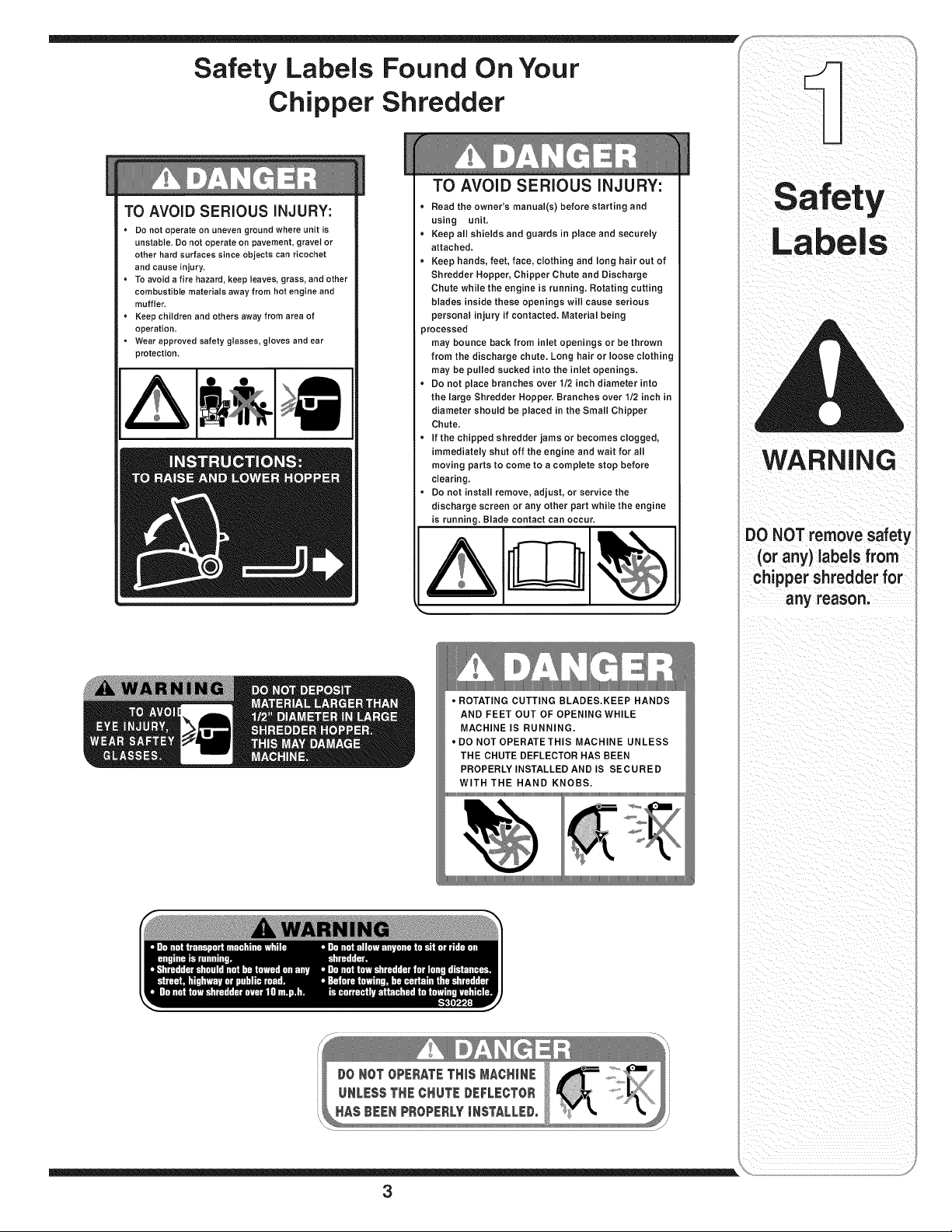
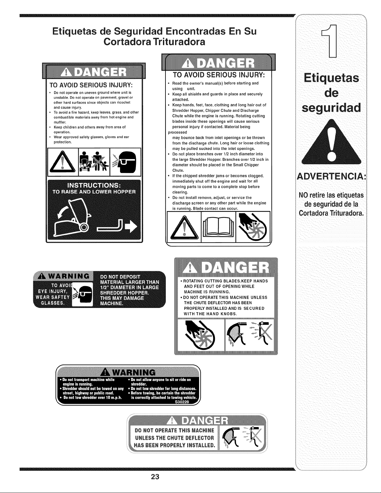
Safety Labels Found On Your
Chipper Shredder
TO AVOID SERIOUS iNJURY:
° Do not operate on uneven ground where unit is
unstable. Do not operate on pavement, gravel or
other hard surfaces since objects can ricochet
and cause injury.
• To avoid a fire hazard, keep leaves, grass, and other
combustible materials away from hot engine and
muffler,
° Keep children and others away from area of
operation.
° Wear approved safety glasses, gloves and ear
protection.
TO AVOID SERIOUS iNJURY:
• Read the owner's manual(s) before starting and
using unit.
• Keep all shields and guards in place and securely
attached.
• Keep hands, feet, face, clothing and long hair out of
Shredder Hopper, Chipper Chute and Discharge
Chute while the engine is running. Rotating cutting
blades inside these openings will cause serious
personal injury if contacted. Material being
_rocessed
may bounce back from inlet openings or be thrown
from the discharge chute. Long hair or loose clothing
may be pulled sucked into the inlet openings.
• Do not place branches over 1/2 inch diameter into
the large Shredder Hopper. Branches over 1/2 inch in
diameter should be placed in the Small Chipper
Chute.
• If the chipped shredder jams or becomes clogged,
immediately shut off the engine and wait for all
moving parts to come to a complete stop before
clearing.
• Do not install remove, adjust, or service the
discharge screen or any other part while the engine
is running. Blade contact can occur.
Labels
WARNING
DO NOT remove safety
(or any) labels from
chipper shredder for
any reason.
3
WARNING
This symbol points
out importantsafety
instructionswhich, if
notfollowed,could
endangerthe personal
i safety and/or property
I ofyourselfand others.
Readand follow all
instructionsinthis
manualbeforeat-
temptingto operate
i this machine. Failure
I to complywith these
instructionsmay result
i in personalinjury.When
you see this symbol.
i HEED ITS WARNING!
i Your Responsibility
Restrictthe use
of this power machine
to personswho read.
i understand
and follow the warnings
and instructions
i inthis manual
and on the machine.
WARNING: Engine Exhaust,some of its constituents, andcertain vehicle compo-
nents contain or emit chemicals knownto State of Californiato cause cancer and
birth defects or other reproductiveharm.
DANGER: This machine was built to be operated according to the rules for safe operation in this
manual. As with any type of power equipment, carelessness or error on the part of the operator can
result in serious injury.This machine is capable of amputating hands and feet and throwing objects.
Failureto observe the followingsafety instructionscould result inserious injuryor death.
Training
1. Read,understand,and followall instructionson the ma- 1.
chineandin the manual(s)beforeattemptingto assemble
andoperate.Keepthis manual ina safe placefor future
and regularreferenceand for orderingreplacementparts.
2. Be familiarwith all controls andtheir proper operation. 2.
Know howto stop the machineanddisengagethem
quickly.
3. Neverallow childrenunder 16years oldto operatethis
machine.Children 16years old andovershould read and 3.
understandthe operationinstructionsandsafety rulesin
this manualand shouldbe trainedand supervisedbya
parent.
4. Neverallow adultsto operatethis machinewithoutproper
instruction. 4.
5. Keepbystanders,helpers,pets,and childrenat least
75 feetfrom the machinewhile it is in operation.Stop
machineif anyoneentersthe area.
6. Neverrunan engineindoorsor in a poorlyventilatedarea. 5.
Engineexhaustcontainscarbon monoxide,an odorless
anddeadly gas. 6.
7. Do notput hands andfeet near rotatingparts or in the
feedingchambersanddischargeopening.Contactwith
the rotatingimpellercan amputatefingers,hands,and
feet.
8. Neverattemptto unclogeither the feed intakeor
dischargeopening, removeor empty bag,or inspectand
repairthe machinewhilethe engineis running.Shutthe
engineoff andwait until all moving partshavecometo a
completestop. Disconnectthespark plugwire andground
it againsttheengine.
Preparation
Thoroughlyinspectthe areawherethe equipmentis to
be used. Removeall rocks,bottles,cans, or otherforeign
objectswhichcould be pickedup or thrownandcause
personalinjuryor damageto the machine.
Alwayswearsafetyglassesor safetygogglesduringopera-
tion or whileperforminganadjustmentor repair,to protect
eyes.Thrownobjectswhich ricochetcan cause serious
injuryto the eyes.
Wearsturdy,rough-soledworkshoesand close-fitting
slacksandshirts. Loosefitting clothesor jewelrycan be
caughtin movableparts.Neveroperatethis machine
in barefeet or sandals.Wearleatherworkgloves when
feedingmaterialin the chipperchute.
Beforestarting,check all bolts and screwsfor propertight-
nessto be surethe machineis in safeworkingcondition.
Also,visually inspectmachinefor any damageat frequent
intervals.
Maintainor replacesafetyandinstructionslabels,as
necessary.
Toavoid personalinjuryor propertydamageuse extreme
care inhandling gasoline.Gasolineis extremelyflammable
andthe vaporsare explosive.Serious personalinjurycan
occurwhengasolineis spilledon yourself oryour clothes
whichcan ignite.Washyour skinand changeclothes
immediately.
a. Useonly an approvedgasolinecontainer.
b. Extinguishallcigarettes,cigars, pipes,andother
sourcesof ignition.
c. Neverfuel machineindoors.
d. Neverremovegas cap oradd fuel whilethe engineis hot
or running.
e. Allow engineto coolat leasttwo minutesbeforerefuel-
ing.
f. Neveroverfill fuel tank. Filltank to no morethan 1/2
inch belowbottomof filler neckto providespacefor fuel
expansion.
g. Replacegasolinecap andtighten securely.
h. If gasolineis spilled,wipe it off theengine and equip-
ment. Movemachineto anotherarea.Wait 5 minutes
beforestartingthe engine.
i. Neverstorethe machineorfuel containerinside where
there is an openflame, spark,or pilot light (e.g.furnace,
waterheater,spaceheater,clothesdryer,etc.)
j. Toreducea fire hazard,keepmachinefree of grass,
leaves,or otherdebris build-up.Clean up oil or fuel
spillageand removeanyfuel soakeddebris.
k. Allowmachineto cool at least5 minutesbeforestoring.
4
Operation
1. Donot puthands andfeet near rotatingpartsor in the
feedingchambersand dischargeopening.Contactwith the
rotatingimpellercanamputatefingers, hands,andfeet.
2. Beforestartingthe machine,makesurethe chipperchute,
feed intake,and cuttingchamberare empty andfree of all
debris.
3. Thoroughlyinspectall materialto be shreddedand remove
any metal,rocks,bottles, cans, or otherforeignobjects
which couldcausepersonalinjuryor damageto the
machine.
4. f it becomesnecessaryto pushmaterialthroughthe
shredderhopper,usea smalldiameterstick. Do notuse
your hands or feet.
5. f the impellerstrikesa foreignobject or ifyour machine
should start makinganunusual noiseor vibration,
immediatelyshutthe engine off.Allow the impellerto come
to a completestop.Disconnectthe sparkplug wire, ground
it againstthe engineandperformthe followingsteps:
a. Inspectfor damage.
b. Repairor replaceany damagedparts.
c. Checkfor anyloose partsand tightento assure
continuedsafeoperation.
6. Donot allow anaccumulationof processedmaterialto build
up inthe dischargearea.This can preventproperdischarge
and result in kickbackof materialthroughthefeed opening.
7. Donot attemptto shredor chip materiallargerthan
specifiedon the machineor inthis manual.Personalinjury
or machinedamagecouldresult.
8. Neverattemptto unclogeitherthe feed intakeor discharge
openingwhilethe engineis running.Shutthe engineoff,
wait until all movingparts havestopped,disconnectthe
spark plug wire andground it againstthe engine before
clearing debris.
9. Neveroperate withoutthe shredderhopper,chipperchute,
or chute deflectorproperlyattachedto the machine.Never
empty or changedischargebagwhilethe engine is running.
10.Keepall guards,deflectorsand safetydevicesin placeand
operatingproperly.
11.Keepyourface andbody backand to theside ofthe chipper
chute whilefeeding materialintothe machineto avoid
accidentalkickbackinjuries.
12.Neveroperatethis machinewithoutgoodvisibility or light.
13.Donot operatethis machineon a paved,gravelor non-level
surface.
14.Donot operatethis machinewhile underthe influenceof
alcohol or drugs.
15.Mufflerandengine becomehot andcan causea burn.Do
nottouch.
16.Neverpickup or carry machinewhilethe engineis running.
Maintenance & Storage
1. Nevertamper withsafetydevices.Checktheir proper
operationregularly.
2. Checkbolts and screwsfor propertightness at frequent
intervalsto keepthe machinein safe workingcondition.
Also,visually inspectmachinefor any damageand repair,if
needed.
3. Beforecleaning,repairing,or inspecting,stopthe engine
andmakecertain the impellerand all movingparts have
stopped.Disconnectthe sparkplugwire and groundit
againstthe engine to preventunintendedstarting.
4. Do notchangethe enginegovernorsettingsor overspeed
theengine.The governorcontrolsthemaximumsafe
operatingspeed of the engine.
5. Maintainor replace safetyandinstructionlabels, as neces-
sary.
6. Followthis manualforsafe loading,unloading,transporting,
andstorageof this machine.
7. Neverstorethe machineorfuel containerinside where
thereis an openflame, sparkor pilot lightsuchas a water
heater,furnace, clothesdryer,etc.
8. Alwaysreferto the operator'smanualfor proper instructions
on off-seasonstorage.
9. If the fuel tank hasto be drained,do this outdoors.
10.Observeproperdisposallaws andregulationsfor gas, oil,
etc. to protectthe environment.
Do not modify engine
Toavoidseriousinjuryor death,do not modifyengine inany
way.Tamperingwiththe governorsettingcan leadto a runaway
engineandcauseit to operateat unsafespeeds.Nevertamper
withfactorysettingof enginegovernor.
Notice regarding Emissions
Engineswhichare certifiedto complywithCaliforniaandfederal
EPAemissionregulationsfor SORE(SmallOff RoadEquipment)
arecertifiedto operateon regularunleadedgasoline,and may
includethefollowingemissioncontrolsystems:EngineModifica-
tion (EM)andThreeWayCatalyst(TWO)ifso equipped.
Your Responsibility
Restrictthe useof this powermachineto personswho read,un-
derstandand followthe warningsand instructionsin this manual
andon the machine.
Practices
WARNING
This symbol points
out important safety
instructions, which if
not followed, could
endanger the personal
safety and/or property
of yourself and others.
Readand follow all
instructions in this man-
ual before attempting to
operate this machine.
Failureto comply with
these instructionsmay
result in personal injury.
When you see this
symbol.
HEED iT S WARNING!
Your Responsibility
Restrictthe use
of this power machine
to persons who read.
understand
and follow the warnings
and instructions
in this manua
and on the machine.
5
Shredder
IMPORTANT
This unit is shipped
without gasoline or
oil in the engine. Be
certainto service
enginewith gasoline
and oil as instructed
in the separate engine
manual before operat-
ing your machine.
NOTE: All references
in this manualto the
left or right side of
the chipper shredder
is from the operating
i position only. Excep-
tions if any will be
specified.
NOTE: This Operators
i Manual covers a range
of product specifica-
tions for various
models. Characteristics
and featuresdiscussed
and/or illustrated in this
manualmay not be ap-
plicableto all models.
MTD LLC reserves the
right to change product
specifications,designs
and equipment without
notice and without
=ncurringobligation.
Figure 3=1
IMPORTANT:Thisunit is shippedwithoutgasolineoroil
in theengine.Becertainto serviceenginewith gasoline
andoilas instructedinthe separateenginemanual
beforeoperatingyour machine.
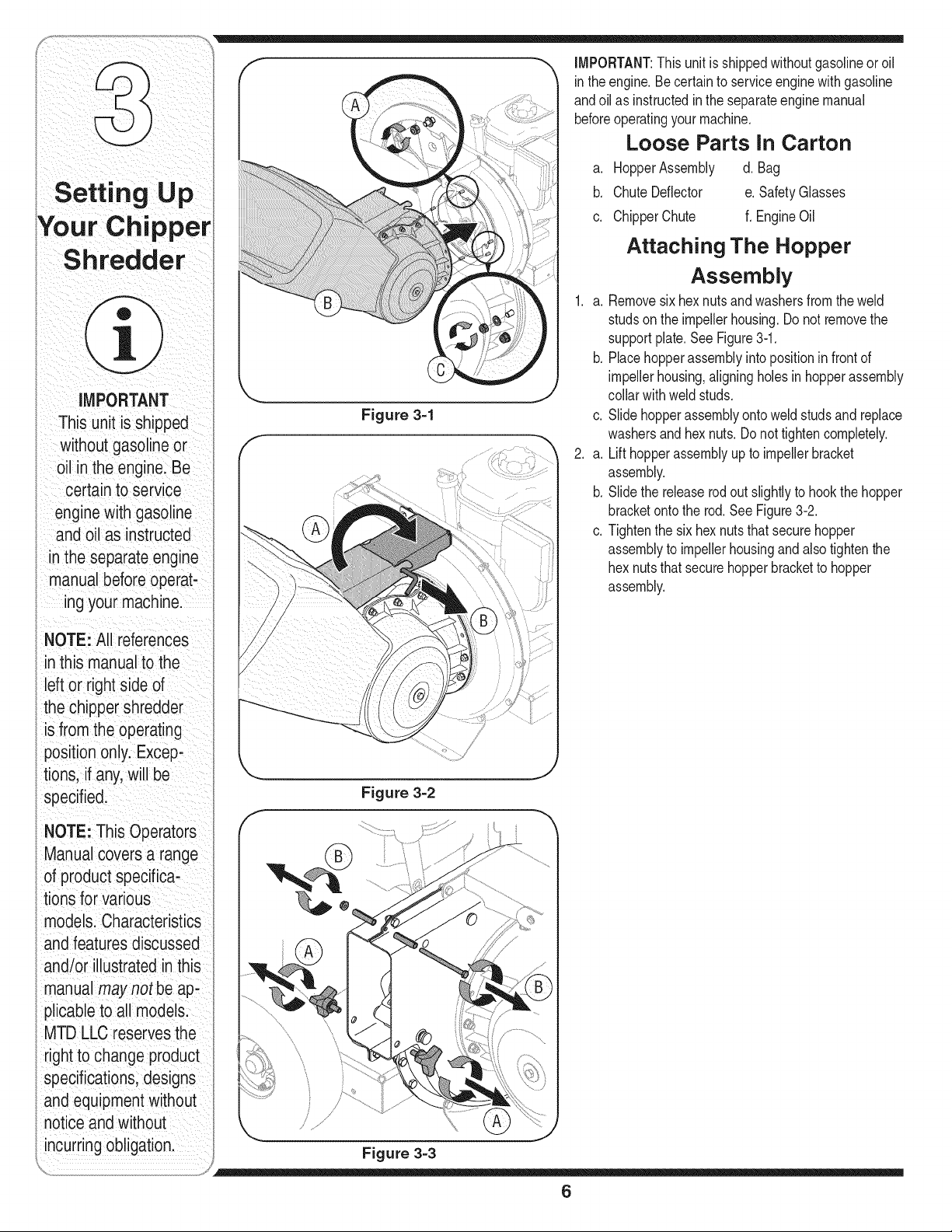
Loose Parts In Carton
a. HopperAssembly d. Bag
b. ChuteDeflector e. SafetyGlasses
c. ChipperChute f. EngineOil
Attaching The Hopper
Assembly
1. a. Removesix hexnuts and washersfromthe weld
studsonthe impellerhousing.Donot removethe
supportplate.See Figure3-1.
b. Placehopperassemblyinto positionin front of
impellerhousing,aligningholesin hopperassembly
collarwithweldstuds.
c. Slide hopperassemblyontoweld studsand replace
washersand hex nuts.Donot tightencompletely.
2. a. Lift hopperassemblyupto impellerbracket
assembly.
b. Slidethe releaserodout slightlyto hookthe hopper
bracketontothe rod.See Figure3-2.
c. Tightenthe six hexnuts that securehopper
assemblyto impellerhousingandalsotightenthe
hex nutsthatsecure hopperbracketto hopper
assembly.
Figure 3-2
Figure 3-3
6
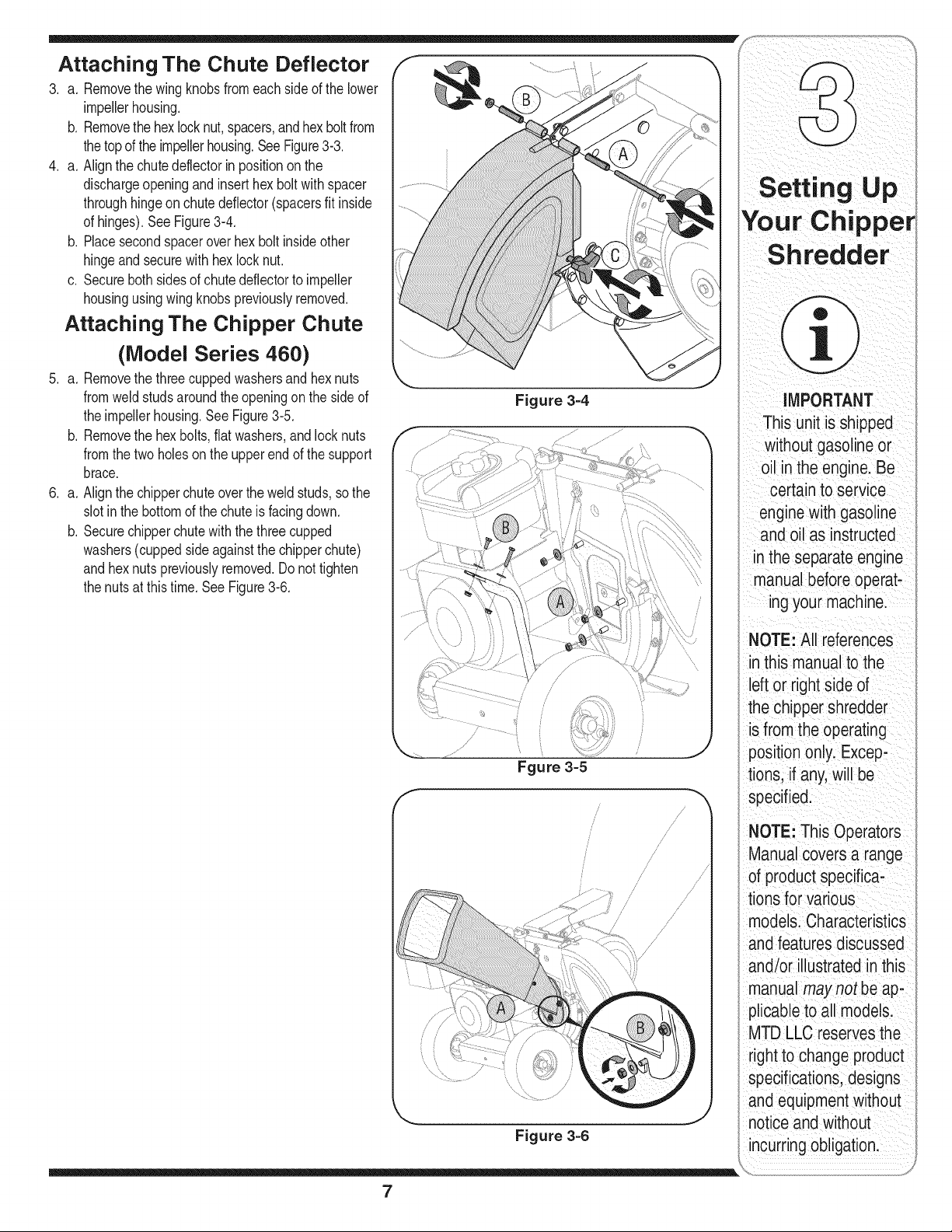
Attaching The Chute Deflector
3. a. Removethe wingknobs fromeach sideof the lower
impellerhousing.
b. Removethe hexlock nut,spacers,andhex boltfrom
the topof theimpellerhousing.SeeFigure3-3.
4. a. Alignthe chutedeflectorin positionon the
dischargeopeningand inserthex boltwith spacer
throughhingeon chutedeflector(spacersfit inside
of hinges).SeeFigure314.
b. Placesecondspaceroverhex bolt insideother
hingeandsecurewith hex lock nut.
c. Securebothsidesof chutedeflectorto impeller
housingusingwingknobspreviouslyremoved.
Attaching The Chipper Chute
(Model Series 460)
5. a. Removethe threecuppedwashersand hexnuts
fromweldstudsaroundthe openingonthe side of
the impellerhousing.SeeFigure3-5.
b. Removethe hexbolts,flat washers,andlock nuts
fromthe twoholeson the upperendof the support
brace.
6. a. Alignthe chipperchuteoverthe weldstuds, sothe
slotinthe bottomof the chuteis facing down.
b. Securechipperchutewith the threecupped
washers(cuppedsideagainstthe chipperchute)
and hexnutspreviouslyremoved.Do nottighten
the nuts at thistime. See Figure316.
Figure 3-4
f
Fgure 3=5
/
/
/
/ /
/
//
/
/
..........1,/
/
/J
/
/
/
//
/
/
Figure 3=6
Your Chipper
Sh redder
IMPORTANT
This unit is shipped
without gasolineor
oil in the engine. Be
certain to service
enginewith gasoline
and oil as instructed
in the separate engine
manual before operat-
ing your machine.
NOTE: All references
in this manualto the
left or right side of
the chipper shredder
is from the operating
position only. Excep-
tions, if any, will be
specified.
NOTE: This Operators
Manual covers a range
of product specifica-
tions for various
models. Characteristics
and features discussed
and/or illustrated in this
manual may not be ap-
plicableto all models.
MTD LLC reservesthe
right to change product
specifications,designs
and equipmentwithout
notice and without
_ncurringobligation.
7
Setting u p
MPORTANT
This unitis shipped
without gasoline or
oil in the enginelae
certain to serv ce
engine with gasoline
an_Joil as instructed
in the separate engine
manUaIbeforeope!at-
ing your machine
NOTE: All references
in this manual tOthe
left or right side of
the chipper shredder
iSfrom the operating
position onlyl Excep;
tions, if any, w Ii be
specified:
i
NOTE: This Operators
ManUalcovers a range
Of product specifiCa:
tions for Various
mode!s:Characteristics
and featuresdiscussed
andior ilUstratedinthiS
manual may not be ap,
plicable toali models!
MTD LLC reservesthe
right to change product
specificationsidesigns
andequipment w thout
notice and without
incurring obligationl
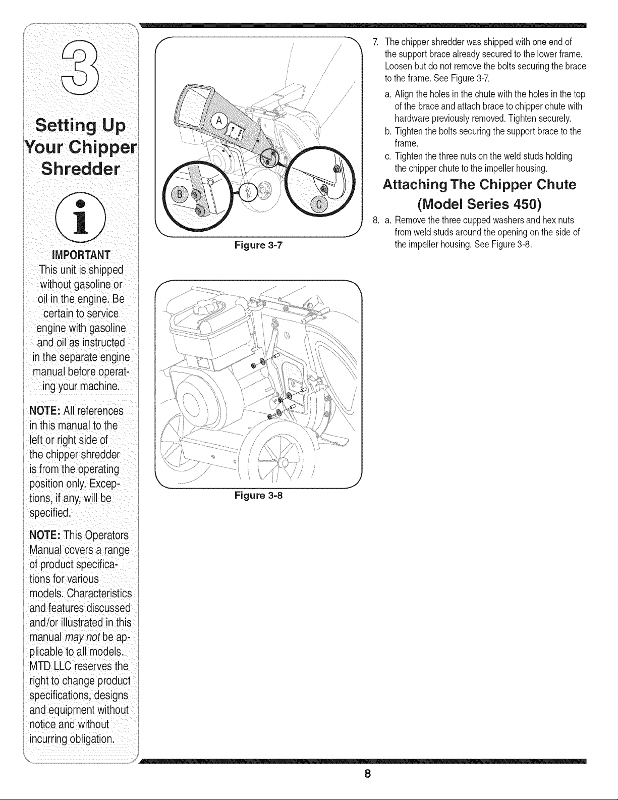
Figure 3-7
/
/
/
/
ji
//
// ///
//
/
7. Thechippershredderwas shippedwithone end of
the supportbracealreadysecuredto the lowerframe.
Loosenbut do not removethebolts securingthe brace
to the frame.See Figure3-7.
a. Alignthe holesin the chutewith the holes in the top
of the braceand attachbraceto chipperchutewith
hardwarepreviouslyremoved.Tightensecurely.
b. Tightenthe boltssecuringthe supportbraceto the
frame.
c. Tightenthe three nutson the weldstudsholding
the chipperchuteto the impellerhousing.
Attaching The Chipper Chute
(Model Series 450)
8. a. Removethethreecuppedwashersandhex nuts
fromweld studsaroundtheopeningon the sideof
the impellerhousing.SeeFigure3-8.
Figure 3=8
8
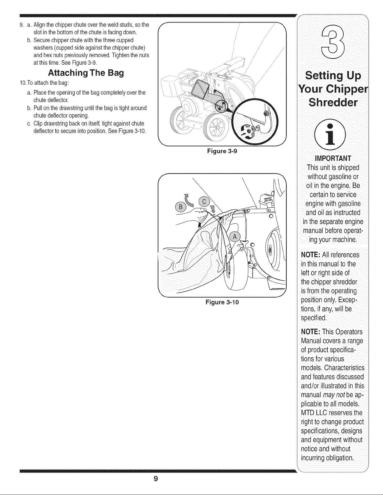
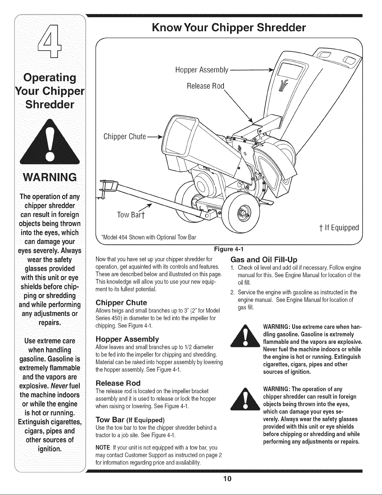
Figure 3=9
Figure 3=10
f
/
/
9. a. Alignthe chipperchuteoverthe weldstuds, sothe
slotinthe bottomof the chuteis facing down.
b. Securechipperchutewith the threecupped
washers(cuppedsideagainstthe chipperchute)
and hexnutspreviouslyremoved.Tightenthe nuts
at this time.SeeFigure3-9.
Attaching The Bag
10.Toattachthe bag:
a. Placethe openingof the bag completelyover the
chutedeflector.
b. Pullon the drawstringuntilthe bag is tight around
chutedeflectoropening.
c. Clipdrawstringback on itself,tight againstchute
deflectorto secureintoposition.See Figure3-10.
Setting Up
YourChippe
Shredder
MPORTANT
This unit iSshipped
without gaso ine or
oilin the enginelBe
Certain to service
engine with gasoline
and Oilas instrUCted
the separate engine
manualbefore operati
ing your machine:
NOTE: All references
this manual tothe
left or right side of
the chipper shredder
is from the operating
position only. Excepi
tions, if any.will be
specified:
NOTE: This OPerators
ManUal covers a range
of product specifiCa,
tions for Various
models: CharacteriStics
and features discussed
and/or iilustrated in this
manual may not be ap.
plicable to all models:
MTD LLC reservesthe
right to Changeproduct
specifications; designs
and equipment without
notice and w thout
incurr ng Obligationl
9
Know Your Chipper Shredder
Operating
WARNING
The operation of any
chipper shredder
can resuff in foreign
objects being thrown
into the eyes, which
candamageyour
eyes severely. Always
wear the safety
glasses provided
with this unit or eye
shields before chip-
i ping or shredding
and while performing
any adjustments or
repairs.
Use extreme care
when handling
i gasoline. Gasoline is
i extremely flammable
and the vapors are
explosive. Never fuel
i the machine indoors
or while the engine
is hot or running.
i Extinguish cigarettes,
cigars, pipes and
other sources of
ignition.
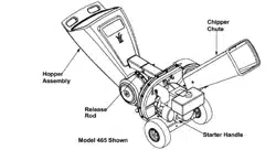
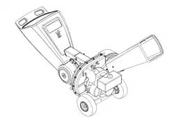
Hopper Assembly-
ReleaseRod
Chipper
*Model464Shownwith 0 TowBar
@
1-If Equipped
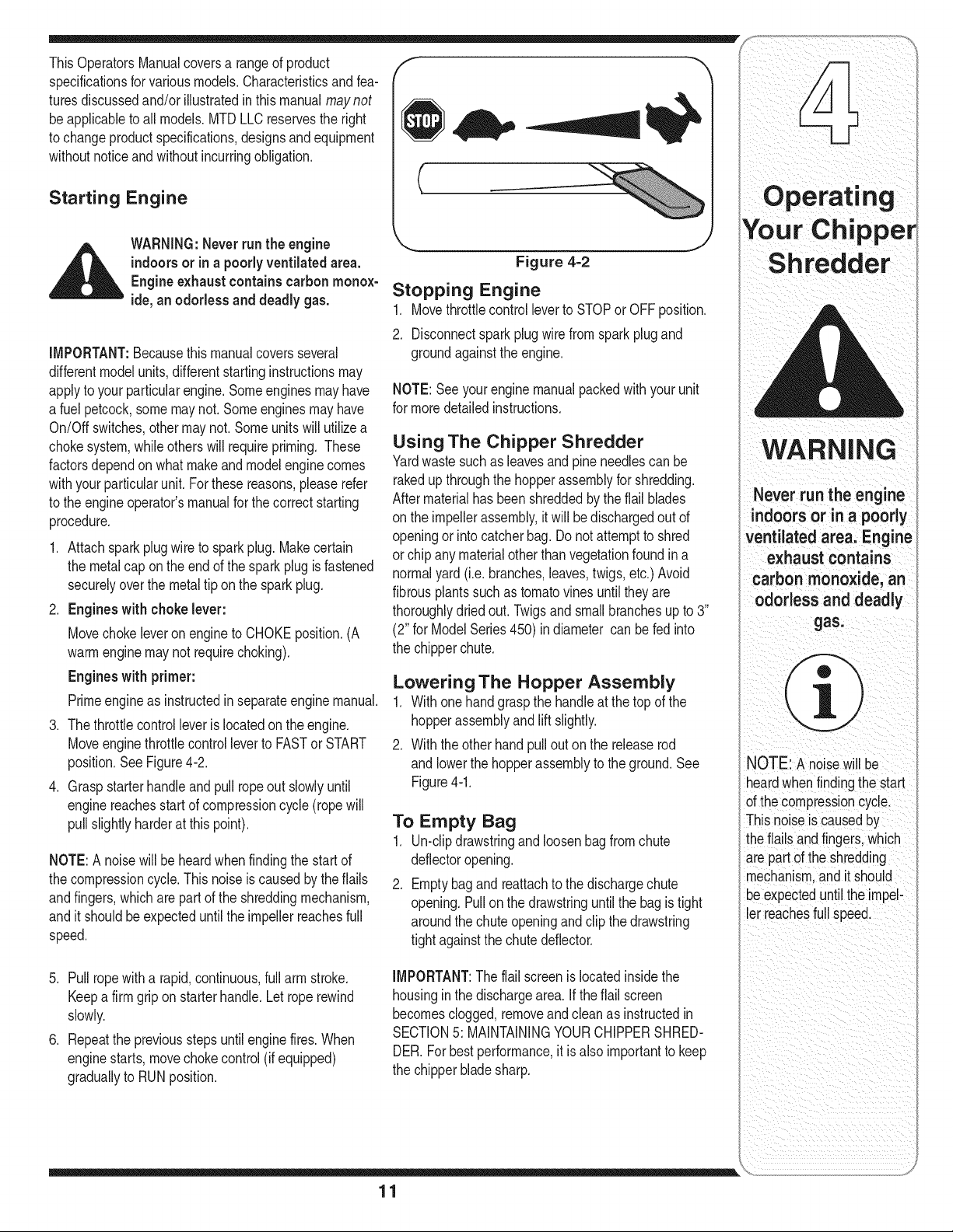
Figure 4=1
Nowthatyou havesetup your chippershredderfor
operation,get aquaintedwith its controlsand features.
Thesearedescribedbelowandillustratedonthis page.
Thisknowledgewillallowyou to use yournewequip-
mentto itsfullestpotential.
Chipper Chute
Allowstwigsandsmallbranchesup to 3" (2"for Model
Series450)indiameterto befed intothe impellerfor
chipping.SeeFigure4-1.
Hopper Assembly
Allowleavesandsmallbranchesupto 1/2diameter
to befed into theimpellerforchippingandshredding.
Materialcan be rakedinto hopperassemblyby lowering
the hopperassembly.See Figure4-1.
Gas and Oil Fill-Up
1. Checkoillevelandaddoil if necessary.Followengine
manualfor this. See EngineManualfor locationof the
oilfill.
2. Servicethe enginewith gasolineas instructedin the
enginemanual. SeeEngineManualfor locationof
gasfill.
WARNING:Useextremecarewhen han-
dling gasoline.Gasoline is extremely
flammable and the vapors are explosive.
NeverfueJthe machine indoorsor while
the engine is hot or running. Extinguish
cigarettes, cigars, pipesand other
sources of ignition.
Release Rod
The releaserod is locatedon the impellerbracket
assemblyandit is usedto releaseor lockthe hopper
whenraisingor lowering.See Figure4-1.
Tow Bar (if Equipped)
Usethetow barto towthe chippershredderbehinda
tractorto ajobsite.See Figure4-1.
NOTE:Ifyour unit isnotequippedwitha towbar,you
maycontactCustomerSupportas instructedon page2
for informationregardingpriceandavailability.
WARNING:Theoperation of any
chippershredder canresultin foreign
objects being thrown intothe eyes,
which can damage your eyes se-
verely. Always wear the safety glasses
providedwith this unit or eye shields
before chippingor shredding and while
performingany adjustments or repairs.
10
ThisOperatorsManualcoversa rangeof product /" _
specificationsforvariousmodels.Characteristicsandfea- _ //1
turesdiscussedand/or illustratedin this manualmay not _,,= _ //[
be applicableto all models.MTDLLCreservesthe right ._ _IiI_
to changeproductspecifications,designsandequipment _
withoutnoticeandwithoutincurringobligation.
Starting Engine (
flARNING: Neverrun the engine
indoorsor in a poorlyventilatedarea.
Engine exhaustcontainscarbonmonox-
ide,an odorless and deadly gas.
IMPORTANT:Becausethismanualcoversseveral
differentmodelunits,differentstartinginstructionsmay
applyto your particularengine.Someenginesmay have
a fuel petcock,some maynot. Someenginesmayhave
On/Off switches,othermaynot. Someunits will utilizea
chokesystem,whileotherswill requirepriming. These
factorsdependon whatmakeand modelenginecomes
withyour particularunit.For thesereasons,pleaserefer
to the engineoperator'smanualforthe correctstarting
procedure.
1. Attachsparkplugwire to spark plug.Makecertain
the metalcap on theend of the sparkplugis fastened
securelyoverthe metal tip on the spark plug.
2. Engines with choke lever:
Movechokeleveronengineto CHOKEposition.(A
warmenginemaynot requirechoking).
Engines with primer:
Primeengineas instructedin separateengine manual.
3. The throttlecontrolleveris locatedon the engine.
Moveenginethrottlecontrol leverto FASTor START
position.SeeFigure4-2.
4. Graspstarterhandleand pullropeout slowlyuntil
enginereachesstart of compressioncycle(rope will
pull slightlyharderat this point).
NOTE:A noisewill beheardwhenfindingthe start of
the compressioncycle.Thisnoiseiscausedby theflails
andfingers,whichare partof the shreddingmechanism,
and itshouldbeexpecteduntilthe impellerreachesfull
speed.
5. Pullropewitha rapid,continuous,fullarm stroke.
Keepa firmgriponstarterhandle.Let roperewind
slowly.
6. Repeatthe previousstepsuntilenginefires.When
enginestarts,movechokecontrol(if equipped)
graduallyto RUNposition.
Figure 4=2
Stopping Engine
1. Movethrottlecontrolleverto STOPor OFFposition.
2. Disconnectspark plug wirefromsparkplugand
groundagainstthe engine.
NOTE:Seeyourenginemanualpackedwithyour unit
for moredetailedinstructions.
Using The Chipper Shredder
Yardwastesuchas leavesand pine needlescan be
rakedupthroughthe hopperassemblyfor shredding.
Aftermaterialhas beenshreddedbythe flail blades
onthe impellerassembly,itwill bedischargedout of
openingor into catcherbag. Donot attemptto shred
orchip anymaterialotherthanvegetationfoundina
normalyard (i.e. branches,leaves,twigs,etc.)Avoid
fibrousplantssuchas tomatovinesuntil theyare
thoroughlydriedout. Twigsand small branchesup to 3"
(2" for ModelSeries450) indiameter can be fed into
the chipperchute.
Lowering The Hopper Assembly
1. Withonehandgraspthe handleat the top of the
hopperassemblyandlift slightly.
2. Withtheother handpullout on the releaserod
andlowerthe hopperassemblyto the ground.See
Figure4-1.
To Empty Bag
1. Un-clipdrawstringand loosenbag from chute
deflectoropening.
2. Emptybagand reattachto the dischargechute
opening.Pull on the drawstringuntilthe bag istight
aroundthe chuteopeningand clip thedrawstring
tightagainstthechutedeflector.
IMPORTANT:The flailscreenislocatedinsidethe
housingin the dischargearea.if theflail screen
becomesclogged,removeand cleanas instructedin
SECTION5: MAINTAININGYOURCHIPPERSHRED-
DER.Forbestperformance,it isalso importantto keep
the chipperbladesharp.
Operat.ing
¥o
WARNING
. vorr.°t,oe°g oo
indoors or in a poorly
Ventilated area: Engine
exhaust contains
carbon monoxide, an
odorless and deadly
NOTE:A noisewill be
heardwhenfindingthestart
ofthe compressioncycle.
Thisnoiseis causedby
theflailsandfingers,which
arepart ofthe shredding
mechanism,andit should
L_eexpecteduntilthe impel-
er reachesfull speed.
11
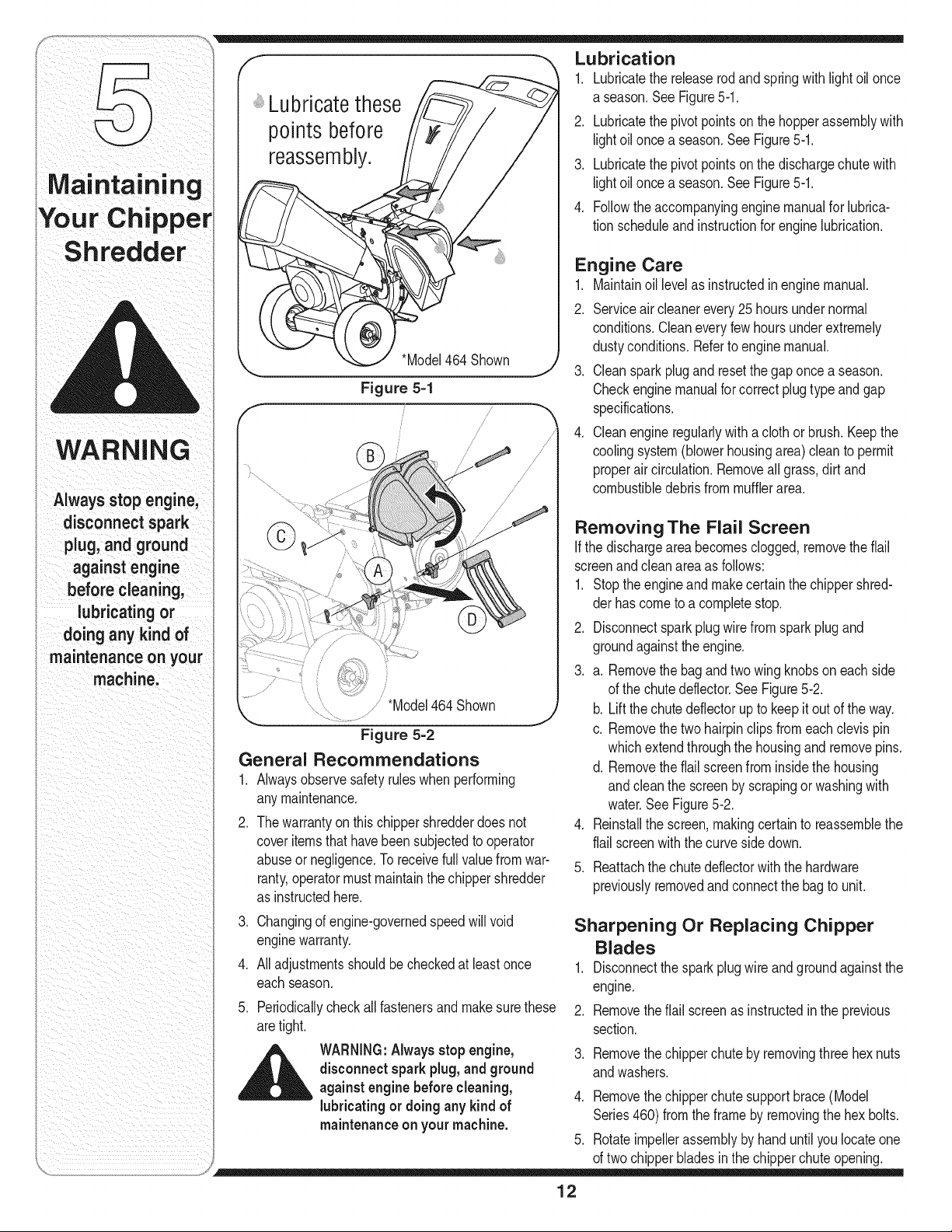
Lubrication
WARNING
Alwaysstopengine,
disconnectspark
plug,and ground
againstengine
before cleaning,
lubricating or
doinganykindof
maintenanceon your
machine.
points before
reassembly.
*Model464Shown
Figure 5-1
/
/*Model464 Shown
Figure 5-2
General Recommendations
1. Alwaysobservesafetyruleswhen performing
anymaintenance.
2. Thewarrantyon this chippershredderdoes not
coveritemsthathavebeensubjectedto operator
abuseornegligence.Toreceivefull valuefrom war-
ranty,operatormustmaintainthe chippershredder
as instructedhere.
3. Changingof engine-governedspeedwill void
enginewarranty.
4. Alladjustmentsshouldbe checkedat leastonce
eachseason.
5.
Periodicallycheckallfastenersand makesurethese
aretight.
_ WARNING:Alwaysstopengine,
disconnect spark plug, and ground
against enginebefore cleaning,
lubricating or doingany kind of
maintenanceon your machine.
1. Lubricatethe releaserodand springwith lightoil once
a season.See Figure5-1.
2. Lubricatethe pivot pointson the hopperassemblywith
lightoil oncea season.See Figure5-1.
3. Lubricatethe pivot pointson the dischargechute with
lightoil oncea season.See Figure5-1.
4. Followtheaccompanyingenginemanualfor lubrica-
tion scheduleandinstructionfor engine lubrication.
Engine Care
1. Maintainoil levelas instructedin enginemanual.
2. Serviceaircleanerevery25 hoursundernormal
conditions.Cleaneveryfewhoursunderextremely
dustyconditions.Referto engine manual.
3. Cleansparkplugand resetthegaponce a season.
Checkenginemanualfor correctplugtype and gap
specifications.
4. Cleanengineregularlywith a cloth or brush. Keepthe
coolingsystem(blowerhousingarea) cleanto permit
properaircirculation.Removeall grass,dirt and
combustibledebrisfrommufflerarea.
Removing The Flail Screen
If the dischargeareabecomesclogged,removetheflail
screenandcleanarea as follows:
1. Stopthe engineand makecertain the chippershred-
derhas cometo a completestop.
2. Disconnectsparkplug wirefrom sparkplug and
groundagainsttheengine.
3. a. Removethe bagand two wingknobson eachside
of the chutedeflector.See Figure5-2.
b. Liftthe chute deflectorupto keepitoutof theway.
c. Removethetwo hairpinclipsfromeach clevispin
whichextendthroughthe housingandremovepins.
d. Removetheflail screenfrom insidethe housing
andcleanthe screenby scrapingor washingwith
water.See Figure5-2.
4. Reinstallthe screen,makingcertainto reassemblethe
flail screenwiththecurvesidedown.
5. Reattachthe chute deflectorwiththe hardware
previouslyremovedand connectthe bag to unit.
Sharpening Or Replacing Chipper
Blades
1. Disconnectthe spark plugwire and groundagainstthe
engine.
2. Removetheflail screenas instructedinthe previous
section.
3. Removethechipperchute by removingthree hexnuts
andwashers.
4. Removethechipperchute supportbrace(Model
Series460)fromthe frameby removingthe hexbolts.
5. Rotateimpellerassemblyby handuntilyoulocateone
of twochipperbladesinthe chipperchute opening.
12
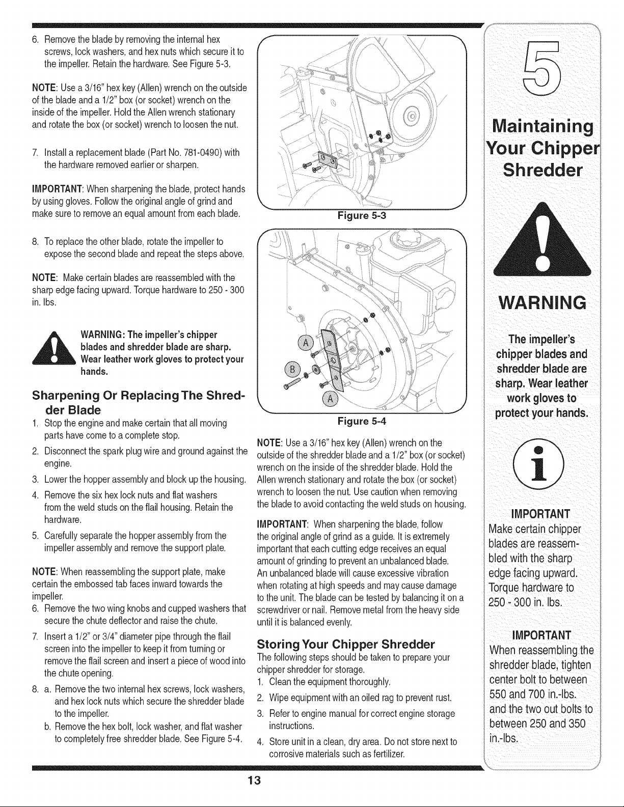
6. Removethe blade by removingthe internalhex
screws,lockwashers,andhexnutswhichsecureit to
the impeller.Retainthe hardware.See Figure5-3.
NOTE: Usea 3/16"hex key(Allen)wrenchonthe outside
of the blade and a 1/2" box(or socket)wrenchonthe
insideof the impeller.HoldtheAllenwrenchstationary
and rotatethe box(or socket)wrenchto loosenthe nut.
7. Installa replacementblade(PartNo.781-0490)with
the hardwareremovedearlieror sharpen.
IMPORTANT:Whensharpeningthe blade,protecthands
by usinggloves.Followthe originalangleof grind and
makesureto removean equalamountfromeachblade.
Figure 5-3
8. To replacethe otherblade,rotatethe impellerto
exposethe secondblade and repeatthe stepsabove.
NOTE: Makecertainbladesarereassembledwith the
sharpedgefacingupward.Torquehardwareto 250- 300
in. Ibs.
,_ WARNING:Theimpeller's chipper
blades and shredderblade are sharp.
Wear leather work gloves to protect your
hands.
Sharpening Or Replacing The Shred-
der Blade
1. Stop theengineand makecertainthat all moving
partshavecometo acompletestop.
2. Disconnectthe sparkplug wireand groundagainstthe
engine.
3. Lowerthe hopperassemblyand block up the housing.
4. Removethe six hex locknutsandflatwashers
fromthe weldstudson theflail housing.Retainthe
hardware.
5. Carefullyseparatethe hopperassemblyfromthe
impellerassemblyandremovethe supportplate.
NOTE:When reassemblingthe supportplate,make
certaintheembossedtab facesinwardtowardsthe
impeller.
6. Removethe two wing knobsand cuppedwashersthat
securethe chute deflectorandraisethe chute.
7. Inserta 1/2"or 3/4" diameterpipethroughthe flail
screenintothe impellerto keepit fromturningor
removethe flail screenand inserta pieceof wood into
the chuteopening.
8. a. Removethe two internalhex screws,lockwashers,
and hexlocknutswhichsecurethe shredderblade
to the impeller.
b. Removethe hexbolt, lock washer,andflat washer
to completelyfree shredderblade.See Figure5-4.
Figure 5-4
NOTE:Usea3/16" hexkey(Allen)wrenchon the
outsideof the shredderbladeanda 1/2" box(or socket)
wrenchonthe insideof the shredderblade.Holdthe
Allenwrenchstationaryandrotatethe box (or socket)
wrenchto loosenthenut. Usecautionwhen removing
the bladeto avoidcontactingthe weldstudson housing.
IMPORTANT:Whensharpeningthe blade,follow
the originalangleof grind as a guide.It is extremely
importantthat eachcuttingedge receivesanequal
amountof grindingto preventan unbalancedblade.
Anunbalancedbladewill causeexcessivevibration
whenrotatingat high speedsand maycause damage
to the unit. Theblade can be testedby balancingit on a
screwdriveror nail. Removemetalfromthe heavyside
until it is balancedevenly.
Storing Your Chipper Shredder
Thefollowingstepsshouldbetakento prepareyour
chippershredderfor storage.
1. Cleantheequipmentthoroughly.
2. Wipeequipmentwithanoiled ragto preventrust.
3. Referto engine manualforcorrectenginestorage
instructions.
4. Storeunitin a clean,dry area. Donot storenextto
corrosivematerialssuchas fertilizer.
13
Maintaining
Your Chipper
Shredder
WARNING
The impelleCs
chipper blades and
shredder blade are
sharp: Wear leather
work gloves to
IMPORTANT
Makecertainchipper
blades are reassem:
bled with the sharp
edge facing upwar&
Torquehardwareto
250,300 in. Ibs.
iMPORTANT
When reasSemblingthe
shredder blade,tighten
center bolt tObetween
550 and 700 ini,lb&
andthe twoOutboltsto
between 250 and 350
in.4b&
For repairs beyond
the minor adjustments
listed here, contact
an authorized service
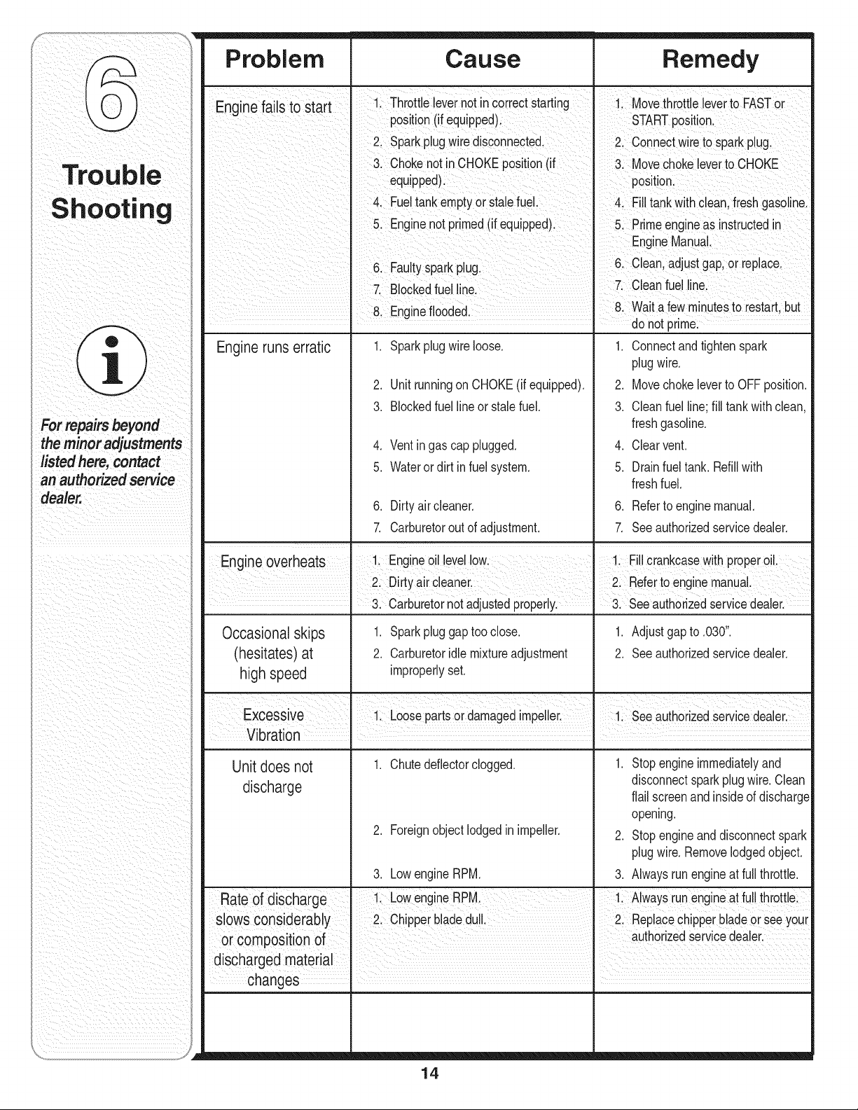
Problem Cause Remedy
Enainef., ailsto Start I Throttle levernotin correctStarting i Movethrott, e everto FASTor
post on (f equpped) STARTpost on
2, Sparkp!ugwire disconnected, 2, Connectwire tospark p!ug,
chokenotincHoKEposition(if cHOKE
equipped): poSiti0nl
FueltankemptyorSta!efuel. tankwithclean,freShgasolinel
&Engine not pdmed(if equipped)Prime engineas .instructedin
6 Faut ark _ 6 ceanadjuStgap 0rrepace
ysp P g: !
Blockedfuel CleanfueI
81Engine flooded, &Wait a few minutesto Festart,but
do not prme:
.
2.
3.
4.
5.
Engineruns erratic
Sparkplugwireloose.
UnitrunningonCHOKE(if equipped).
Blockedfuellineor stalefuel.
Ventingas cap plugged.
Waterordirt infuel system.
6. Dirty aircleaner.
7. Carburetorout of adjustment.
1. Connectandtightenspark
plugwire.
2. Movechokeleverto OFF position.
3. Cleanfuel line;fill tankwithclean,
freshgasoline.
4. Clearvent.
5. Drainfuel tank. Refillwith
freshfuel.
6. Referto enginemanual.
7. Seeauthorizedservicedealer.
Engine overheats 1. Engineoil levellow. _ 1. Fillcrankcasewith properoil.
2. Dirty aircleaner. I 2. Referto enginemanual,
• 3. Carburetornotadjustedproperly.
Occasional skips
(hesitates) at
high speed
Unit does not
discharge
1. Sparkpluggap tooclose.
2. Carburetoridlemixtureadjustment
improperlyset.
1. Chutedeflectorclogged.
2. Foreignobject lodgedin impeller.
3. LowengineRPM.
3. Seeauthorizedservicedealer.
1. Adjustgap to .030".
2. Seeauthorizedservicedealer.
1. Stop engineimmediatelyand
disconnectsparkplugwire.Clean
flail screenandinsideof discharge
opening.
2. Stop engineand disconnectspark
plugwire.Removelodgedobject.
3. Alwaysrunengineat full throttle.
Rate of discharge 1 LowengineRPM. 1. Alwaysrunengineat fullthrottle.
slows considerably I 2. Chipperbladedul. I 2. Replacechipperbladeor seeyour
or composition of authorzed servcedeaer.
discharged material I I
changes ,
14

NOTES
Use this page to make notes and write down important information.
15
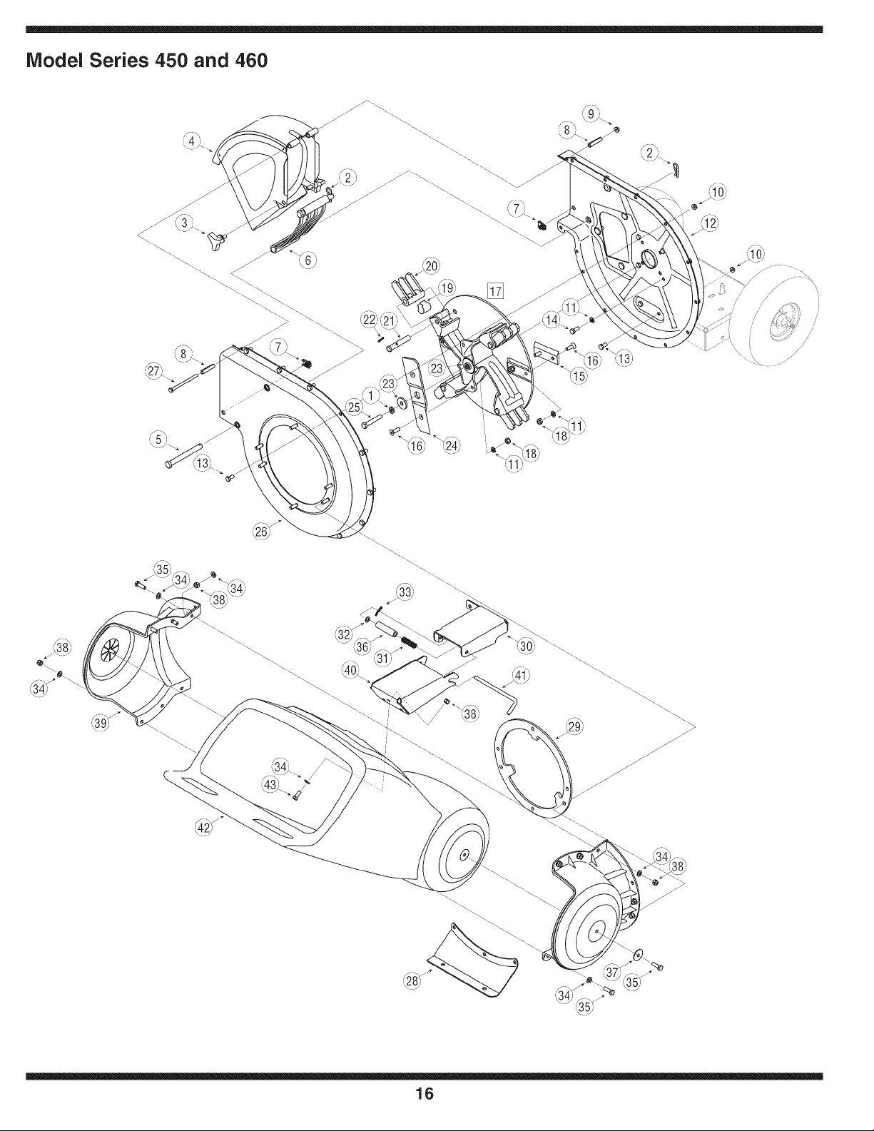
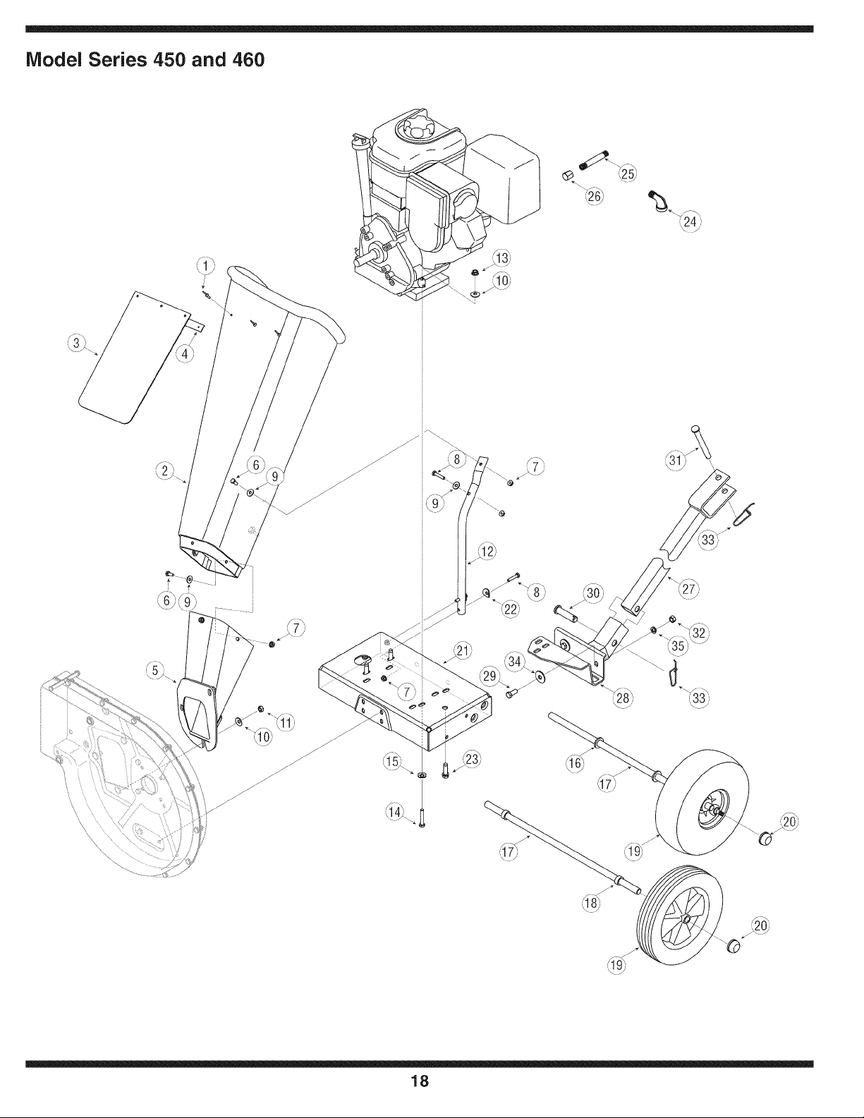
Model Series 450 and 460
j_
i •¢/i
16
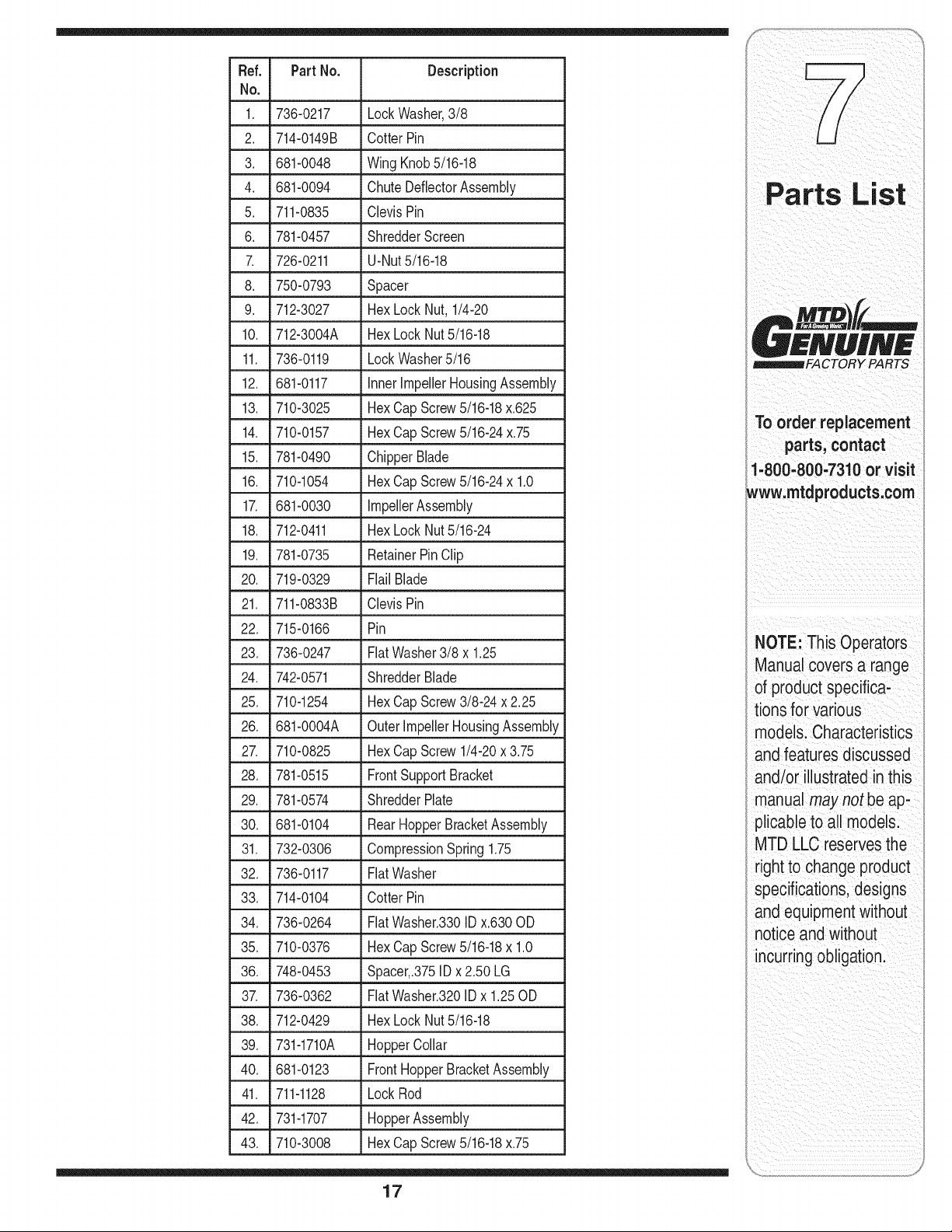
Ref. PartNo. Description
No,
1. 736-0217 Lock Washer,3/8
2. 714-0149B CotterPin
3. 681-0048 WingKnob5/16-18
4. 681-0094 ChuteDeflectorAssembly
5. 711-0835 ClevisPin
6. 781-0457 ShredderScreen
7. 726-0211 U-Nut5/16-18
8. 750-0793 Spacer
9. 712-3027 HexLockNut, 1/4-20
10. 712-3004A Hex Lock Nut5/16-18
11. 736-0119 LockWasher5/16
12. 681-0117 InnerImpellerHousingAssembly
13. 710-3025 Hex CapScrew5/16-18x.625
14. 710-0157 Hex CapScrew5/16-24x.75
15. 781-0490 ChipperBlade
16. 710-1054 Hex CapScrew5/16-24x 1.0
17. 681-0030 impellerAssembly
18. 712-0411 Hex Lock Nut5/16-24
19. 781-0735 RetainerPinClip
20. 719-0329 Flail Blade
21. 711-0833B ClevisPin
22. 715-0166 Pin
23. 736-0247 FlatWasher3/8 x 1.25
24. 742-0571 ShredderBlade
25. 710-1254 HexCapScrew3/8-24 x 2.25
26. 681-0004A OuterlmpellerHousingAssembly
27. 710-0825 HexCapScrew 1/4-20x 3.75
28. 781-0515 FrontSupportBracket
29. 781-0574 ShredderPlate
30. 681-0104 RearHopperBracketAssembly
31. 732-0306 CompressionSpring1.75
32. 736-0117 FlatWasher
33. 714-0104 CotterPin
34. 736-0264 FlatWasher.330ID x.630OD
35. 710-0376 HexCapScrew5/16-18x 1.0
36. 748-0453 Spacer,.375IDx2.50 LG
37. 736-0362 FlatWasher.320ID x 1.25OD
38. 712-0429 HexLock Nut5/16-18
39. 731-1710A HopperCollar
40. 681-0123 FrontHopperBracketAssembly
41. 711-1128 LockRod
42. 731-1707 HopperAssembly
43. 710-3008 HexCapScrew5/16-18x.75
17
££NUIN£
_FACTORY PARTS
TO order replacement
parts, contact
1.8oo:8oo.7aloor
www:mtaprOaucts;oom
NOTE: This Operators
ManUalcovers a range
of product specifiCa;
tions for Various
models:CharaCteristics
and featuresd iscussed
and/or illustrated in this
manual may not be ap*
plicable to all model&
MTD LLC reservesthe
right to change product
specifications;designs
and equipmentwithout
notice and without
incurring obligation
i__ _ii_: !_ iiiiiiiii_!__ii _iii___i_i
i_ _ii_ _ii_ i _ i
i i i i i i i i i i i i ii
Model Series 450 and 460
,_20)
18
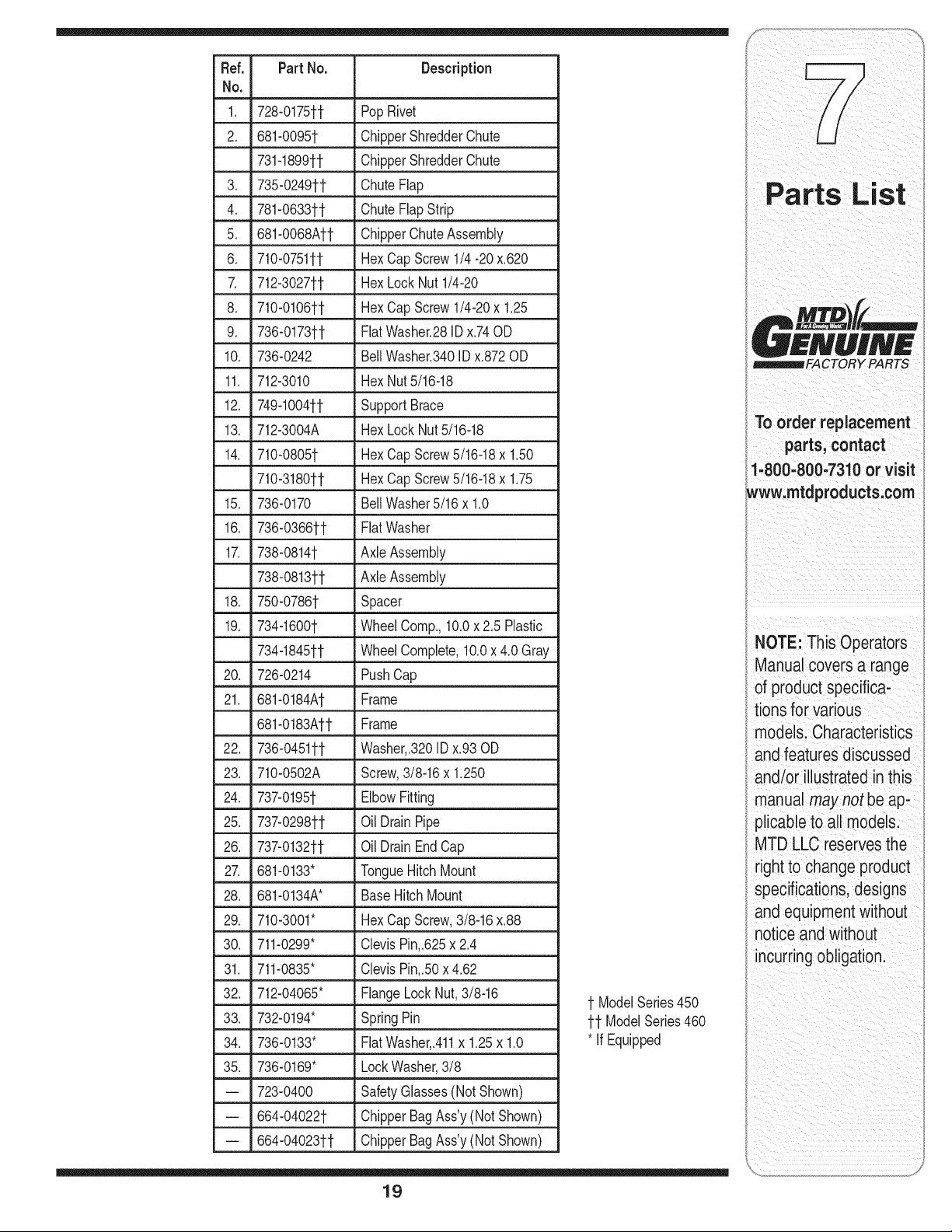
Ref. PartNo. Description
No,
1. 728-0175tt PopRivet
2. 681-0095t ChipperShredderChute
731-1899tt ChipperShredderChute
3. 735-0249tt ChuteFlap
4. 781-0633tt ChuteFlapStrip
5. 681-O068Att ChipperChuteAssembly
6. 710-0751tt HexCapScrew 1/4-20 x.620
7. 712-3027tt HexLock Nut 1/4-20
8. 710-0106tt HexCapScrew 1/4-20x 1.25
9. 736-0173tt FlatWasher.28ID x.74OD
10. 736-0242 BellWasher.340ID x.872OD
11. 712-3010 HexNut5/16-18
12. 749-1004tt SupportBrace
13. 712-3004A HexLockNut5/16-18
14. 710-0805t Hex CapScrew5/16-18x 1.50
710-3180tt HexCapScrew5/16-18x 1.75
15. 736-0170 BellWasher5/16x 1.0
16. 736-0366tt FlatWasher
17. 738-0814t AxleAssembly
738-0813tt AxleAssembly
18. 750-0786t Spacer
19. 734-1600t WheelComp.,10.0x 2.5 Plastic
734-1845tt WheelComplete,10.0x 4.0 Gray
20. 726-0214 PushCap
21. 681-0184At Frame
681-0183Aft Frame
22. 736-0451tt Washer,.3201Dx.93OD
23. 710-0502A Screw,3/8-16x 1.250
24. 737-0195t ElbowFitting
25. 737-0298tt Oil DrainPipe
26. 737-0132tt Oil DrainEndCap
27. 681-0133" TongueHitchMount
28. 681-0134A* BaseHitchMount
29. 710-3001" HexCapScrew,3/8-16x.88
30. 711-0299" ClevisPin,.625x2.4
31. 711-0835" ClevisPin,.50x4.62
32. 712-04065" FlangeLockNut,3/8-16
33. 732-0194" SpringPin
34. 736-0133" FlatWasher,.411x 1.25x 1.0
35. 736-0169" LockWasher,3/8
-- 723-0400 SafetyGlasses(Not Shown)
-- 664-04022t ChipperBagAss'y(Not Shown)
-- 664-04023tt ChipperBagAss'y(Not Shown)
t ModelSeries450
tt ModelSeries460
* if Equipped
19
££NUIN£
_FACTORY PARTS
TO order replacement
parts, contact
1.8oo:aoo.Taloor
www:mtaprOaucts;oom
NOTE: This Operators
ManUalcovem a range
of product specifiCa;
tions for Various
models:CharaCteristics
and featuresd iscussed
and/or illustrated in this
manual may not be ap*
plicable to all model&
MTD LLC reservesthe
right to change product
specifications;designs
and equipmentwithout
notice and without
incurring obligation
i__ _iI_L!_ iiiiiiiii_!__ii _iii___i_i
i i i i i i i i i i i i ii

MANUFACTURER'S LiMiTED WARRANTY FOR
The limited warranty set forth below is given by MTD LLC with
respect to new merchandise purchased and used in the United States
and/or its territories and possessions, and by MTD Products Limited
with respect to new merchandise purchased and used in Canadaand/
or its territories and possessions (either entity respectively, "MTD").
"MTD" warrants this product (excluding its Normal Wear Parts and
Attachments as described below) against defects in material and
workmanship for a period of two (2) years commencing on the date
of original purchase and will, at its option, repair or replace, free of
charge, any part found to be defective in materials or workmanship.
This limited warranty shall only apply if this product has been
operated and maintained in accordance with the Operator's Manual
furnished with the product, and has not been subject to misuse,
abuse, commercial use, neglect, accident, improper maintenance,
alteration, vandalism, theft, fire, water, or damage because of other
peril or natural disaster. Damage resulting from the installation or use
of any part, accessory or attachment not approved by MTD for use
with the product(s) covered by this manual will void your warranty as
to any resulting damage.
Normal Wear Parts are warranted to be free from defects in material
and workmanship for a period of thirty (30) days from the date of
purchase. Normal wear parts include, but are not limited to items
such as: batteries, belts, blades, blade adapters, tines, grass bags,
wheels, rider deck wheels, seats, snow thrower skid shoes, friction
wheels, shave plates, auger spiral rubber and tires.
Attachments-- MTD warrants attachments for this product against
defects in material and workmanship for a period of one (1) year,
commencing on the date of the attachment's original purchase or
lease. Attachments include, but are not limited to items such as:
grass collectors and mulch kits.
HOWTO OBTAINSERVICE:Warranty service is available, WITH
PROOFOFPURCHASE,through your local authorized service dealer.
To locate the dealer in your area:
In the U.S.A.
Check your Yellow Pages, or contact MTD LLC at RO. Box 361131,
Cleveland, Ohio 44136-0019, or call 1-800-800-7310, 1-330-220-
4683 or log on to our Web site at www.mtdproducts.com.
In Canada
Contact MTD Products Limited, Kitchener, ON N2G4J1, or call 1-800-
668-1238 or log on to our Web site at www.mtdcanada.com.
This limited warranty does not provide coverage in the following
cases:
a. The engine or component parts thereof. These items may carry a
separate manufacturer's warranty. Refer to applicable manufactur-
er's warranty for terms and conditions.
b. Log splitter pumps, valves, and cylinders havea separate one-
year warranty.
c. Routine maintenance items such as lubricants, filters, blade
sharpening, tune-ups, brake adjustments, clutch adjustments,
deck adjustments, and normal deterioration of the exterior finish
due to use or exposure.
d. Service completed by someone other than an authorized service
dealer.
e. MTD does not extend any warranty for products sold or exported
outside of the United States and/or Canada,and their respective
possessions and territories, except those sold through MTD's
authorized channels of export distribution.
f. Replacement parts that are not genuine MTD parts.
g. Transportation charges and service calls.
h. MTD does not warrant this product for commercial use.
No implied warranty, including any implied warranty of
merchantability of fitness for a particular purpose, applies after
the applicable period of express written warranty above as to the
parts as identified. No other express warranty, whether written or
oral, except as mentioned above, given by any person or entity,
including a dealer or retailer, with respect to any product, shall
bind MTD. Duringthe period of the warranty, the exclusive remedy
is repair or replacement of the product as set forth above.
The provisions as set forth in this warranty provide the sole and
exclusive remedy arising from the sale. MTD shall not be liable
for incidental orconsequential loss or damage including, without
limitation, expenses incurred for substitute or replacement lawn
care services or for rental expenses to temporarily replace a
warranted product.
Some states do not allow the exclusion or limitation of incidental
or consequential damages, or limitations on how long an implied
warranty lasts, so the above exclusions or limitations may not apply
to you.
In no event shaft recovery of any kind be greater than the amount of
the purchase price of the product sold. Alteration of safetyfeatures of
the product shall void this warranty. You assume the risk and liability
for loss, damage, or injuryto you and your property and/or to others
and their property arising out of the misuse or inability to use the
product.
This limited warranty shall not extend to anyone other than the
original purchaser or to the person for whom it was purchased as a
gift.
HOWSTATELAW RELATESTO THIS WARRANTY: This limited
warranty gives you specific legal rights, and you may also have other
rights which vary from state to state.
IMPORTANT: Owner must present Original Proof of Purchase to
obtain warranty coverage.
MTD LLC, P.O. BOX 361131 CLEVELAND, OHiO 44136=0019; Phone: 1=800=800=7310, 1=330=220=4683
MTD Canada Limited = KITCHENER, ON N2G 4J1; Phone 1=800=668=1238
GDOC-lO0015 REV. B
Seguridad=Ensamblaje=Operaci6n=Consejos y T6cnicas.Mantenimiento-Soluci6n de problemas.Lista de Parte=GrantJas
A AL L P A O
/
/
/
/
/
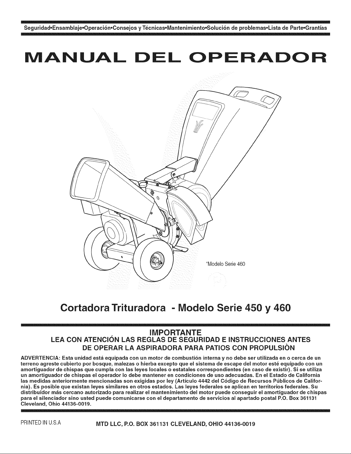
*ModeloSerie460
Cortadora Trituradora - Modelo Serie 450 y 460
IMPORTANTE
LEA CON ATENCION LAS REGLAS DE SEGURIDAD E INSTRUCCIONES ANTES
DE OPERAR LA ASPIRADORA PARA PATIOS CON PROPULSI(_)N
ADVERTENCIA: Esta unidad est_ equipada con un motor de combusti6n interna y no debe set utilizada en o cerca de un
terreno agreste cubierto por bosque, malezas o hierba excepto que el sistema de escape del motor est6 equipado con un
amortiguador de chispas clue cumpla con las leyes locales o estatales correspondientes (en caso de existir). Si se utiliza
un amortiguador de chispas el operador Io debe mantener en condiciones de uso adecuadas. En el Estado de California
las medidas anteriormente mencionadas son exigidas pot ley (Articulo 4442 del C6digo de Recursos P_blicos de Califor=
nia). Es posible que existan leyes similares en otros estados. Las leyes federales se aplican en territorios federales. Su
distribuidor m_s cercano autorizado para realizar el mantenimiento del motor puede conseguir el amortiguador de chispas
para el silenciador sino usted puede comunicarse con el departamento de servicios al apartado postal P.O. Box 361131
Cleveland, Ohio 44136=0019.
PRINTEDIN U.S.A MTD LLC, P.O. BOX 361131 CLEVELAND, OHIO 44136=0019
Este manual de operador es una parte irnportante de su nueva rn_quina cortadora trituradora. Le
ayudar_ a rnontar, preparar y rnantener la unidad para obtener los rnejores resultados.
Por favor lea y cornprenda el contenido del manual.
r =
Indlce
Etiquetas de seguridad .................................... 23
Pr_cticas de seguridad en la operaci6n ......... 24
Configuraci6n de la cortadora trituradora ..... 26
Funcionarniento de la cortadora trituradora.. 30
IVlarltenirniento de la cortadora trituradora .... 32
Soluci6n de problernas .................................... 34
Lista de las piezas ............................................ 16
Garantia ............................................................. 36
B squeda y registro del n rnero de rnodelo
ANTES DE COMENZAR A ENSAMBLAR SU NUEVO
EQUIPO,
por favor Iocalice la placa del modelo en el equipoy copie la
informaci6n en la placa modelo a la derecha. Para encontrar
la placa de modelo col6quese detr_.sde la unidad en la
posici6n del operadory mire hacia abajo en la parte posterior
de la cubierta. La presente informaci6n resultar_,necesaria
para el uso del sitio web del fabricante y / o para solicitar
ayuda del Departamento de Asistencia al Cliente o de un
distribuidor autorizado.
N0merode modelo
b
www.rntdproducts.corn
N0merode serie
MTD LLC
P.O= BOX 3(}1131
CLEVELAND, OH 44136
330=220=4683
800-800-73t 0
Asistencia al Cliente
Por favor, NO devuelva la unidad al rninorista a quien se la adquiri6 sin contactarse
prirnero con el Departamento de Asistencia al Cliente.
Encaso de tener problemas para ensamblar este producto o de tener dudas con respecto a los controles, funcionamiento o
mantenimientodel mismo, puede solicitar la ayuda de los expertos. Elijaentre las opciones que se presentan a continuaci6n:
1. Visite mtdproducts.com.
2. Si desea contactarse con un Representantedel Departamentode Asistencia al Cliente, por favor comuniquese al 1(800)
800-7310.
3. El fabricante del motor es el responsable de todas las cuestiones relacionadas con el rendimiento,potencia de salida,
especificaciones,garantia y mantenimiento del motor. Por favor,para mayor confirmaci6n, consulte el manual del propietario/
operador del fabricante del motor que es enviado,en un paquete por separado,junto con su unidad.
22
Etiquetas de Seguridad Encontradas En Su
Cortadora Trituradora
TO AVOID SERIOUS iNJURY:
• Do not operate on uneven ground where unit is
unstable, Do not operate on pavement, gravel or
other hard surfaces since objects can ricochet
and cause injury,
• To avoid a fire hazard, keep leaves, grass, and other
combustible materials away from hot engine and
muffler,
• Keep children and others away from area of
operation,
• Wear approved safety glasses, gloves and ear
protection,
TO AVOID SERIOUS iNJURY:
• Read the owner's manual(s) before starting and
using unit.
• Keep all shields and guards in place and securely
attached.
• Keep hands, feet, face, clothing and long hair out of
Shredder Hopper, Chipper Chute and Discharge
Chute while the engine is running. Rotating cutting
blades inside these openings will cause serious
personal injury if contacted. Material being
processed
may bounce back from inlet openings or be thrown
from the discharge chute. Long hair or loose clothing
may be pulled sucked into the inlet openings.
• Do not place branches over 1/2 inch diameter into
the large Shredder Hopper. Branches over 1/2 inch in
diameter should be placed in the Small Chipper
Chute.
• If the chipped shredder jams or becomes clogged,
immediately shut off the engine and wait for all
moving parts to come to a complete stop before
clearing,
• Do not install remove, adjust, or service the
discharge screen or any other part while the engine
is running. Blade contact can occur.
iI _i_ i _i_i_iiiiiiii_i_i ii! i_i
NO retire las efquetas
de seguridad de la
CortadoraTrtu radora;
23
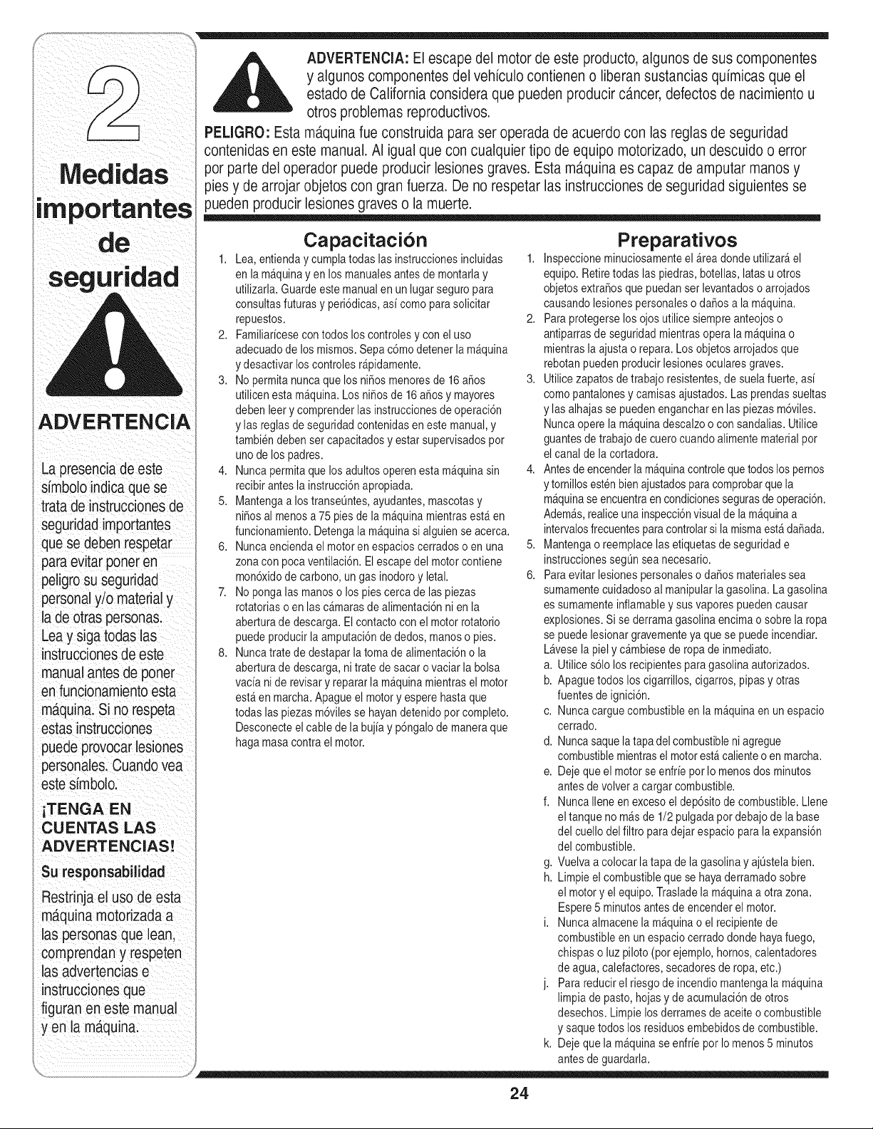
ADVERTENClA:El escapedel motorde este producto algunosde sus componentes
y algunoscomponentesdel vehiculocontieneno liberansustanciasquimicasque el
i simboloindicaquese
i tratade instruccionesde
} seguridadimportantes
i quese debenrespetar
paraevitarponeren
i peligrosu seguridad
personaly/o materialy
lade otraspersonas.
Leay sigatodas las
instruccionesde este
manualantesde poner
en funcionamiento esta
ma.quina.Si no respeta
estas instrucciones
i puedeprovocarlesiones
I personales.Cuandovea
estesimbolo.
iTENGA EN
CUENTAS LAS
ADVERTENClAS!
Su responsabilidad
I Restrinjael uso de esta
i ma,quinamotorizadaa
I las personasque lean,
comprendany respeten
I las advertenciase
instruccionesque
figuran en estemanual
y en la m_tquina.
estadode Californiaconsideraque puedenproducircancer,defectosde nacimientou
otros problemasreproductivos.
PELIGRO: Estam_,quinafueconstruidapara seroperada de acuerdocon las reglasde seguridad
contenidasen este manual.AI igualque con cualquiertipo de equipomotorizado,un descuidoo error
por parte del operadorpuede producirlesionesgraves.Estam_.quinaes capaz de amputarmanosy
pies y de arrojarobjetoscon granfuerza. De no respetarlas instruccionesde seguridadsiguientesse
puedenproducirlesionesgraveso la muerte.
Capacitaci6n
1. Lea,entienday cumplatodas las instruccionesincluidas 1.
en la m_quinay en los manualesantesde montarlay
utilizarla.Guardeestemanualen unlugar seguropara
consultasfuturas y peri6dicas,asi como parasolicitar
repuestos. 2.
2. Familiaricesecon todos los controlesy con el uso
adecuadodelos mismos.Sepac6mo detenerla m_quina
y desactivarloscontrolesr_pidamente.
3. No permitanuncaque losni_os menoresde 16a_os 3.
utilicenesta m_quina.Losni_os de 16 a_osy mayores
debenleery comprenderlas instruccionesde operaci6n
y lasreglas de seguridadcontenidasen estemanual,y
tambiendebenset capacitadosy estar supervisadospot
unode los padres.
4. Nuncapermitaquelos adultosoperen esta m_quinasin 4.
recibirantes la instrucci6napropiada.
5. Mantengaa los transeQntes,ayudantes,mascotasy
ni6osal menosa 75 piesde la m_quinamientrasest_en
funcionamiento.Detengala m_quinasi alguien seacerca.
6. Nuncaenciendael motoren espacioscerrados o en una 5.
zonacon pocaventilaci6n. El escapedel motorcontiene
mon6xidode carbono,ungas inodoroy letal. 6.
7. No pongalas manoso los pies cercade las piezas
rotatoriaso en lasc_marasde alimentaci6nni enla
aberturade descarga.El contactocon el motorrotatorio
puedeproducirla amputaci6ndededos, manoso pies.
8. Nuncatratede destaparla toma de alimentaci6no la
aberturade descarga,nitrate de sacaro vaciarla bolsa
vacia nide revisary repararla m_quinamientrasel motor
est_en marcha.Apagueel motory esperehasta que
todas laspiezas m6vilesse hayandetenidopot completo.
Desconecteelcablede la bujiay p6ngalode maneraque
haga masacontrael motor.
Preparativos
Inspeccioneminuciosamenteel _rea dondeutilizar_el
equipo.Retiretodas las piedras,botellas,latasu otros
objetosextra_osque puedanserlevantadoso arrojados
causandolesionespersonaleso da_os a la m_quina.
Para protegerselosojos utilicesiempreanteojoso
antiparrasde seguridadmientrasopera la mAquinao
mientrasla ajustao repara.Los objetosarrojadosque
rebotanpueden producirlesionesocularesgraves.
Utilicezapatos de trabajoresistentes,de suelafuerte,asi
comopantalonesy camisasajustados.Las prendassueltas
y lasalhajasse puedenengancharen las piezas m6viles.
Nuncaoperela m_quinadescalzoo con sandalias.Utilice
guantesde trabajode cuero cuandoalimentematerialpot
el canalde la cortadora.
Antesdeencenderla mAquinacontrolequetodoslospernos
y tomillosestenbienajustadosparacomprobarquela
m_quinaseencuentraencondicionessegurasde operaci6n.
Adem_s,realiceuna inspecci6nvisualde la m_quinaa
intervalosfrecuentespara controlarsi la mismaestAda5ada.
Mantengao reemplacelasetiquetasde seguridade
instruccionessegQnsea necesario.
Paraevitar lesionespersonaleso da_os materialessea
sumamentecuidadosoal manipularla gasolina.La gasolina
es sumamenteinflamabley susvaporespuedencausar
explosiones.Sise derramagasolinaencimao sobre la ropa
se puedelesionargravementeya que se puedeincendiar.
Lavesela piely c_mbiesede ropade inmediato.
a. Utilice s61olosrecipientesparagasolina autorizados.
b. Apaguetodos los cigarrillos,cigarros,pipas y otras
fuentesde ignici6n.
c. Nuncacarguecombustibleen la m_quinaen un espacio
cerrado.
d. Nuncasaquelatapa delcombustibleniagregue
combustiblemientrasel motorest_ calienteo en marcha.
e. Dejeque el motorse enfrie por Io menosdos minutos
antesde volvera cargarcombustible.
f. NuncaIleneen excesoel dep6sitode combustible.Llene
eltanque no m_s de 1/2 pulgadapot debajode la base
del cuello delfiltro paradejar espaciopara laexpansi6n
del combustible.
g. Vuelvaa colocar la tapa de la gasolinay ajQstelabien.
h. Limpieel combustibleque se hayaderramadosobre
el motory elequipo.Trasladela m_quinaaotra zona.
Espere5 minutosantesde encenderel motor.
i. Nuncaalmacenela m_quinao el recipientede
combustibleen un espaciocerradodonde hayafuego,
chispaso luzpiloto (por ejemplo,hornos,calentadores
de agua, calefactores,secadoresde ropa,etc.)
j. Para reducirel riesgode incendio mantengala m_quina
limpia de pasto,hojasy deacumulaci6ndeotros
desechos.Limpie los derramesdeaceiteo combustible
y saque todos losresiduosembebidosde combustible.
k. Dejeque la m_quinase enfrie pot Io menos5 minutos
antesde guardarla.
24
Funcionamiento
1. Nopongalas manoso lospies cercade las piezas
rotatoriaso en lasc_marasde alimentaci6nnien la
abertura de descarga.El contactocon el motorrotatorio
puedeproducirla amputaci6ndededos, manoso pies.
2. Antes de encenderla m_quinacompruebequeel canalde
lacortadora, latoma de alimentaci6ny lac_mara de corte
est#,nvaciasy sin desechos.
3. Inspeccioneminuciosamentetodo el materialquedesea
triturary saque losobjetos met_licos,piedras,botellas,
latas u otrosobjetos extra6osquepuedenocasionar
lesioneso da_ar la m_quina.
4. Si es necesarioempujarel materialpor latolva de la
trituradorause un palode all,metro peque6o.Noutilice las
manosni los pies.
5. Si el motorgolpeaun objeto extra_oo si lam_quina
empiezaa producir un sonidopococomQno unavibraci6n,
apague el motorde inmediato.Dejequeel motorse
detenga porcompleto.Desconecteel cable de la bujia,
p6ngalode maneraque haga masacontrael motory siga
estos pasos:
a. Inspeccionela m_quinaparavet si est_ daSada.
b. Repareo reemplacelaspiezas da_adas.
c. Controlesi haypiezasflojas y ajL]stelaspara asegurar
quela m_quinafuncionede maneraseguray continua.
6. Nopermitaque se acumulematerialprocesadoen la zona
de descarga.Elmismopuedeobstaculizarla descarga
adecuaday provocarel retornodel materiala travesde la
abertura de alimentaci6n.
7. Nointentetriturar nipicar materialde mayortama_oal
especificadoen la m_quinao en este manual.Se podrian
producirlesioneso da_os.
8. Nuncatratede destaparla tomade alimentaci6no la
abertura de descargamientrasel motorestaen marcha.
Apagueel motory esperehastaque todas laspiezas que
se muevense hayandetenidopor completo,desconecte
el cable de la bujiay p6ngalode maneraque haga masa
contra el motorantesde sacar losescombros.
9. Nuncaopere la m_quinasin que latolva de latrituradora,
el canal de la cortadorao el canaldeflectoresten
correctamenteconectadosa la m_quina.Nuncavacie ni
cambie la bolsade descargamientrasel motorest_en
marcha.
10.Mantengatodos losprotectores,deflectoresydispositivos
de seguridadensu lugar yen buenascondiciones.
11.Mientrasalimentamaterialdentro de lam_quinamantenga
su rostroy su cuerpodetr_s y haciaun costadodel
canal de la cortadorapara evitarlesionespot retrocesos
accidentales.
12.Nuncaopere estam_quinasinbuenavisibilidado
iluminaci6n.
13.Noopereesta m_quinaen superficiespavimentadas,con
grava o desniveladas.
14.Noopereesta m_quinaestandobajo losefectosdel alcohol
o de drogas.
15.El silenciadory el motorse calientany puedencausar
quemaduras.Nolostoque.
16.Nuncalevanteo transportela m_quinacuandoel motor
est_ encendido.
Mantenimiento y
almacenarniento
1. Nuncaaltere los dispositivosde seguridad.Controle
peri6dicamentequefuncionencorrectamente.
2. Controlefrecuentementeque todos lospernosy tornillos
estenbienajustadospara comprobarquela m_quinase
encuentraen condicionessegurasde funcionamiento.
Adem_s,realiceunainspecci6nvisualde la m_quina
para controlarsi la mismaest_ daSaday repareladeset
necesario.
3. Antesde limpiar,repararo inspeccionarla m_quina,
detengael motory compruebeque el mismoy quetodas
las piezasm6vilesse hayandetenido.Desconecteel cable
de la bujia y p6ngalohaciendomasacontrael motorpara
evitarque se enciendaaccidentalmente.
4. Nocambie la configuraci6ndel reguladordel motor ni
aceleredemasiadoel mismo. El reguladordel motor
controlalavelocidad m_ximasegurade funcionamientodel
motor.
5. Mantengao reemplacelasetiquetasde seguridade
instruccionessegQnsea necesario.
6. Siga las instruccionesde este manualparacargar,
descargar,transportary almacenarde maneraseguraesta
m_quina.
7. Nuncaalmacenela m_quinao el recipientede combustible
en un espaciocerrado dondehayauna llamaexpuesta,
chispaso piloto de encendidocomopor ejemplo,
calentadorde agua, homo,secadorde ropa,etc.
8. Consultesiempreel manualde operaci6nparaobtener
instruccionesadecuadasparael almacenamientofuerade
temporada.
9. Sidebe vaciarel tanquede combustible,h_galoal aire
libre.
10.Respetelas normasreferentesa la disposici6ncorrecta
y lasreglamentacionessobregasolina, aceite,etc. para
protegerel medicambiente.
No modifique el motor
Paraevitarlesionesgraveso la muerte,no modifiqueel motor
bajoningunacircunstancia.Sicambiala configuraci6ndel
reguladorel motorpuededescontrolarsey operar a velocidades
inseguras.Nunca cambiela configuraci6nde f_bricadel
reguladordel motor.
Aviso referido a emisiones
Los motoresque est_ncertificadosy cumplencon las
regulacionesde emisionesfederalesEPAy de Californiapara
SORE(Equipospeque_ostodo terreno)est_ncertificados
para operarcon gasolinacomL]nsin plomoy puedenincluirlos
siguientessistemasde controlde emisiones:Modificaci6nde
motor(EM)y catalizadorde tres vias (TWO)si est_nequipados
de esa manera.
Su responsabilidad
Restrinjael uso de este equipomotorizadoalas personasque
lean,comprendany respetenlasadvertenciase instrucciones
quefiguranen estemanualyen la m_quina.
25
i
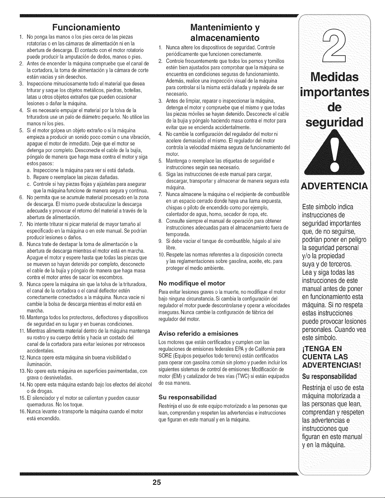
ADVERTENCIA
Estesimbolo indica
instruccionesde
seguridadimportantes
que, de no seguirse,
podrian poneren peligro
la seguridadpersonal
y/o la propiedad
suyay deterceros.
Lea y siga todaslas
instruccionesde este
manualantes de porter
en funcionamientoesta
maquina.Si no respeta
estasinstrucciones
puedeprovocarlesiones
personales.Cuandoyea
estesimbolo.
iTENGA EN
CU ENTA LAS
DVERTENCIAS!
Su responsabilidad
Restrinjael usode esta
maquinamotorizadaa
las personasque lean,
comprendany respeten
las advertenciase
instruccionesque
figuranen este manual
y en la maquina.
Configuraci6n
Ortadora
IMPORTANTE
Estaunidadse envia sin
i gasolinani aceite en el
motor.Antes de operar
la ma.quinacargue el
motorcon gasolinay
' aceite comose indicaen
el manualdel motor por
separado.
NOTA:Todaslas
referenciasque contiene
estemanualsobrelos
ladosderechoo izquierdo
de lacortadoratrituradora
i se hacenobservandola
i mismadesdela posici6n
i de operaci6nOnicamente.
Siexistieraalguna
excepci6n,la mismasera
i especificada.
i NOTA: EsteManual
deloperadorcubreuna
gamade especificaciones
de productosde
variosmodelos.Las
caracteristicasy
i funcionesincluidasy/o
ilustradasen estemanual
puedenno seraplicables
atodos los modelos.
MTD LLCse reservael
derechode modificarlas
i especificacionesde los
productos,los dise_os
y el equiposin prevJo
avJsoy sin generar
i responsabilidadpor
i obligacionesde ningQn
i tipo.
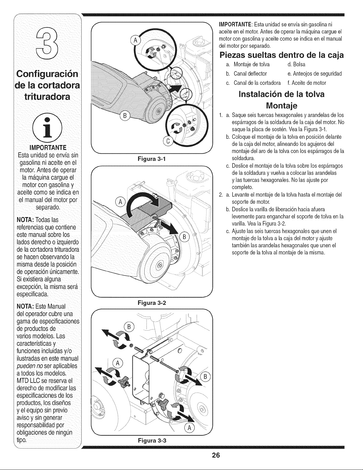
IMPORTANTE:Estaunidadse envfa singasolinani
aceiteenel motor.Antesdeoperarla m&quinacargueel
motorcon gasolinay aceite comose indicaen el manual
delmotorporseparado.
Piezas sueltas dentro de la caja
a. Montajedetolva d. Bolsa
b. Canaldeflector e. Anteojosde seguridad
c. Canaldela cortadora f. Aceitedemotor
Figura 3-1
Instalacion de la tolva
Montaje
1. a. Saqueseistuercashexagonalesy arandelasde los
esp&rragosde la soldadurade lacaja del motor.No
saquela placade sost_n.Veala Figura3-1.
b. Coloqueel montajede la tolvaen posici6ndelante
dela cajadel motor,alineandolos agujerosdel
montajedel arode latolvacon losesp&rragosde la
soldadura.
c. Desliceel montajedela tolva sobrelosesp&rragos
dela soldaduray vuelvaa colocarlas arandelas
y las tuercashexagonales.No lasajuste por
completo.
2. a. Levanteel montajede la tolvahastael montajedel
soportede motor.
b. Deslicela varillade liberaci6nhaciaafuera
levementepara engancharel soportedetolva en la
varilla.Veala Figura3-2.
c. Ajustelas seis tuercashexagonalesqueunenel
montajede la tolvaa la cajadel motory ajuste
tambi_nlasarandelashexagonalesque unen el
soportede latolvaal montajede la misma.
Figura 3=2
Figura 3=3
26
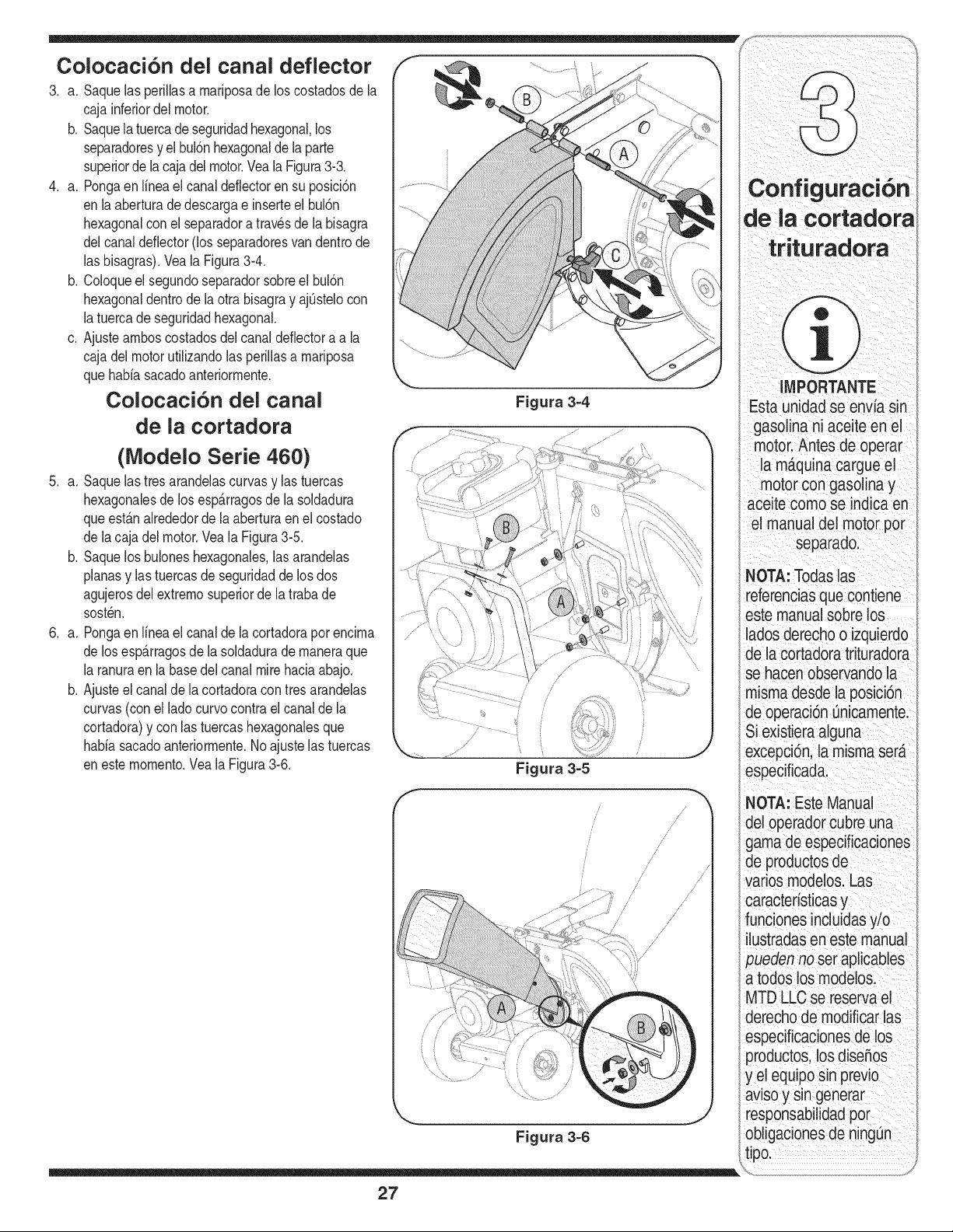
Colocaci6n del canal deflector
3. a. Saquelasperillasa rnariposade loscostadosde la
caja inferiordel motor.
b. Saquelatuercade seguridadhexagonal,los
separadoresy el bul6nhexagonaldela parte
superiorde lacajadelmotor.Veala Figura313.
4. a. Pongaen Nneael canaldeflectoren su posici6n
en laaberturadedescargae inserteel bul6n
hexagonalconel separadora travesdela bisagra
del canaldeflector(los separadoresvandentrode
lasbisagras).Vea la Figura314.
b. Coloqueel segundoseparadorsobreel bul6n
hexagonaldentrode laotra bisagray ajOstelocon
latuercade seguridadhexagonal.
c. Ajustearnboscostadosdel canal deflectoraa la
caja delmotor utilizandolas perillasa rnariposa
que bahiasacadoanteriorrnente.
Colocacion del canal
de la cortadora
(Modelo Serie 460)
5. a. Saquelastresarandelascurvasy las tuercas
hexagonalesde los esp_.rragosde la soldadura
queestanalrededorde laaberturaen el costado
de lacaja delmotor.Veala Figura315.
b. Saquelosbuloneshexagonales,las arandelas
planasy lastuercasde seguridadde losdos
agujerosdel extrernosuperiorde latrabade
sost_n.
6. a. Pongaen Nneael canaldela cortadorapor encirna
de los esp_.rragosde la soldadurade rnaneraque
laranuraen labasedel canalmirehaciaabajo.
b. Ajusteel canalde lacortadoracon tresarandelas
curvas(con el ladocurvocontrael canalde la
cortadora)y con las tuercashexagonalesque
bahiasacadoanteriorrnente.Noajustelastuercas
en esternornento.Veala Figura316.
f
Figura 3-5
/
/
/
/
/
/
..........1,/
/
/J
/
/
/
//
/
/
Figura 3-6
¢onfiguraci6n
de ia cortadora
IMPORTANTE
Estaunidadse envfasin
gasolinani aceite en el
motor.Antes de operar
la m_.quinacargue el
motor congasolinay
aceitecomo se indicaen
el manual del motorpot
separado.
NOTA:Todaslas
referenciasque contiene
estemanualsobrelos
ladosderechoo izquierdo
de la cortadoratrituradora
se hacenobservandola
mismadesdela posici6n
de operaci6nOnicamente.
Siexistieraalguna
excepci6n,la mismaserD.
especificada.
NOTA:EsteManual
del operadorcubreuna
gamade especificaciones
de productosde
variosmodelos.Las
caracterfsticasy
funcionesincluidasy/o
ilustradasen estemanual
_uedennoset aplicables
a todoslosmodelos.
MTDLLCse reservael
derechode modificarlas
especificacionesde los
productos,los dise_os
y el equiposin previo
avisoy sin generar
responsabilidadpor
obligacionesde ningOn
tipo.
27
Configuraci6n
Ortadora
IMPORTANTE
Estaunidadse envia sin
i gasolinani aceite en el
motor.Antes de operar
la ma.quinacargue el
motorcon gasolinay
' aceite comose indicaen
el manualdel motor por
separado.
NOTA:Todaslas
referenciasque contiene
estemanualsobrelos
ladosderechoo izquierdo
de lacortadoratrituradora
i se hacenobservandola
i mismadesdela posici6n
i de operaci6nOnicamente.
Siexistieraalguna
excepci6n,la mismasera
i especificada.
i NOTA: EsteManual
deloperadorcubreuna
gamade especificaciones
de productosde
variosmodelos.Las
caracteristicasy
i funcionesincluidasy/o
ilustradasen estemanual
puedenno seraplicables
atodos los modelos.
MTD LLCse reservael
derechode modificarlas
i especificacionesde los
productos,los dise_os
y el equiposin prevJo
avJsoy sin generar
i responsabilidadpor
i obligacionesde ningQn
i tipo.
,,
Figura 3-7
/
/
/
/
/
/
/
/
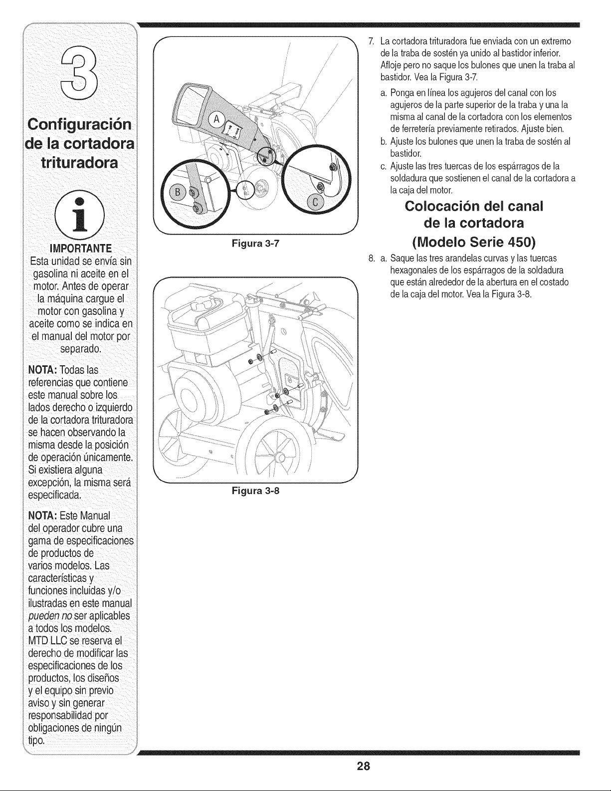
Lacortadoratrituradorarueenviadacon un extremo
dela trabade sost_nya unidoal bastidorinferior.
Aflojeperonosaquelos bulonesque unen la trabaal
bastidor.Vea la Figura3-7.
a. Pongaenlinea losagujerosdel canalcon los
agujerosde la partesuperiorde latraba y unala
mismaal canalde lacortadoracon loselementos
deferreteriapreviamenteretirados.Ajustebien.
b. Ajustelos bulonesqueunen la traba de sost_nal
bastidor.
c. Ajustelas tres tuercasde los esp_.rragosde la
soldaduraque sostienenel canalde lacortadoraa
lacaja del motor.
Colocaci6n del canal
de la cortadora
(Modelo Serie 450)
8. a. Saquelas tres arandelascurvasy lastuercas
hexagonalesdelos esp_.rragosde la soldadura
queest_.nalrededordela aberturaen el costado
dela cajadel motor.VealaFigura3-8.
Figura 3=8
28
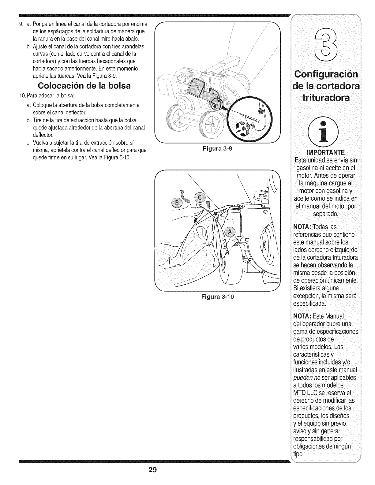
9, a, Pongaen lineael canaldela cortadorapor encirna
de los esp_.rragosde la soldadurade rnaneraque
laranuraen labasedel canalmirehaciaabajo,
b, Ajusteel canalde lacortadoracon tresarandelas
curvas(con el ladocurvocontrael canalde la
cortadora)y con las tuercashexagonalesque
habiasacadoanteriorrnente,Eneste rnornento
aprietelas tuercas,Veala Figura3-9.
Colocaci6n de la bolsa
10,Paraadosarla bolsa:
a, Coloquela aberturade la bolsacornpletarnente
sobreel canaldeflector.
b, Tire dela tira deextracd6n hastaquela bolsa
quedeajustadaakededorde la aberturadelcanal
deflector.
c, Vuelvaa sujetarla fira deextracci6nsobresi
rnisrna,apri_telacontra el canaldeflectorparaque
quedefirrneen su lugar,Vea la Figura3-10,
f
/ //,'/
/
' /
/ /
/
/ /
/
de la cortadora
Figura 3=9
IMPORTANTE
Estaunidadse envia sin
gasolinani aceite en el
motor.Antes de operar
la m_.quinacargue el
motor congasolinay
aceitecomo se indicaen
el manual del motorpor
separado.
Figura 3=10
NOTA:Todaslas
referenciasque contiene
estemanualsobrelos
ladosderechoo izquierdo
de la cortadoratrituradora
se hacenobservandola
mismadesdela posici6n
de operacbn0nicamente.
Siexistieraalguna
excepci6n,la mismaser_.
especificada.
NOTA: Este Manual
del operadorcubre una
gama de especificaciones
de productosde
varios modelos. Las
caracteristicas y
funciones incluidasy/o
ilustradasen este manual
ser aplicables
os los modelos.
MTD LLC se reserva el
derecho de modificar las
especificacionesde los
productos,los dise_os
y el equiposin previo
tar
responsabilidadpor
obligac_onesde ningOn
)0.
29
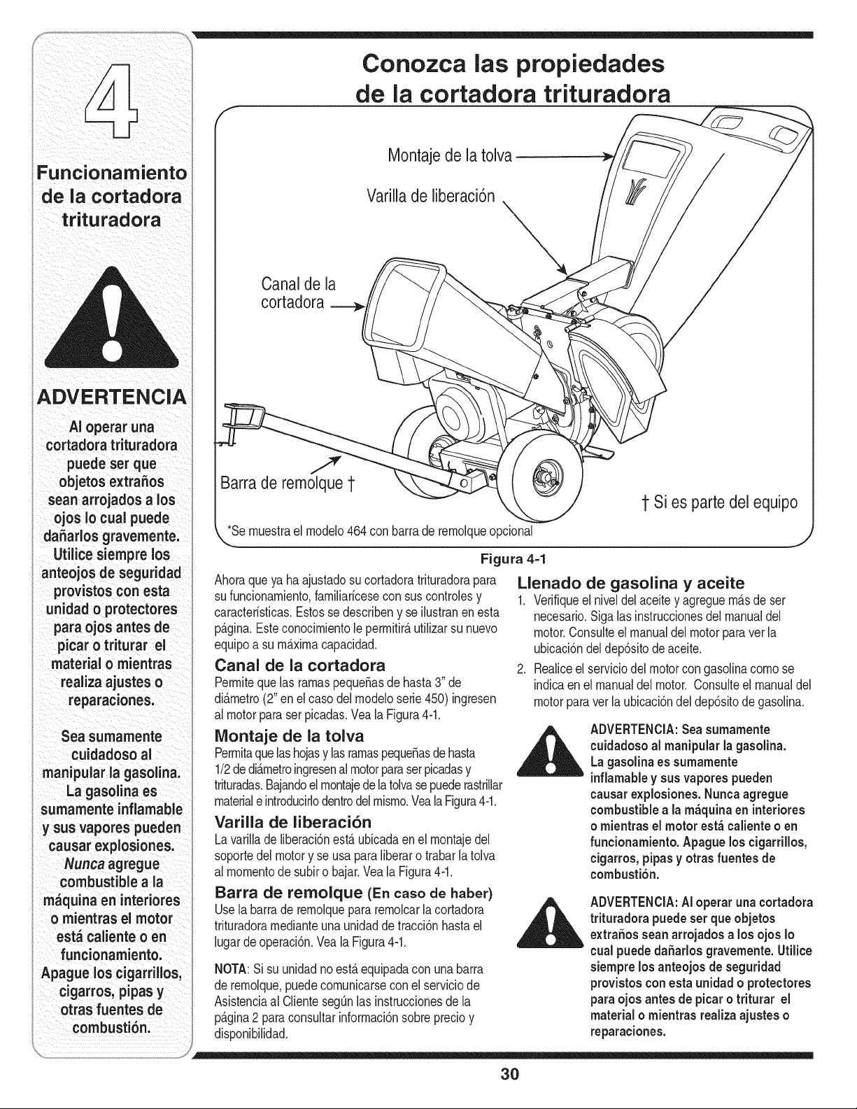
Conozca las propiedades
ADVERTENCIA
AI operaruna
cortadoratrituradora
puedeser que
objetosextraSos
scan arrojadosa los
ojos io cuai puede
daSarlosgravemente.
Utilicesiemprelos
; anteojosde seguridad
provistoscon esta
unidado protectores
para ojos antesde
picaro triturar el
material o mientras
realizaajusteso
reparaciones.
Sea sumamente
cuidadoso aJ
manipuiar la gasoiina.
i La gasolinaes
sumamenteinflamable
y susvapores pueden
causarexplosiones.
Nuncaagregue
combustible a ia
m_quina en interiores
o mientras el motor
est_ calienteo en
, funcionamiento.
Apaguelos cigarrillos,
cigarros,pipasy
otras fuentes de
combustibn.
de la cortadora trituradora
Montaje de la tolva
Varilla de liberaci6n
Canal de la
cortadora
J
Barra de remolque1 @
1 Si es parte del equipo
*Se rnuestrael rnodelo464 con barrade lue
Figura 4=1
Ahoraqueya ha ajustadosu cortadoratrituradorapara
su funcionarniento,farniliaricesecon sus controlesy
caracteristicas.Estosse describeny se ilustranen esta
p_.gina.Esteconocirnientole perrnitir_,utilizarsu nuevo
equipoa su rn_.xirnacapacidad.
Canal de la cortadora
Perrnitequelas rarnaspeque_asde hasta3" de
di_.rnetro(2" enel casodelrnodeloserie450) ingresen
al motorparaserpicadas.Veala Figura4-1.
Montaje de la tolva
Perrnitaquelashojasy lasrarnaspeque_asde hasta
1/2de di_.rnetroingresenalmotorparaserpicadasy
trituradas.Bajandoelrnontajedelatolvase puederastrillar
materialeintroducNodentrodelrnisrno.VealaFigura4-1.
Varilla de liberaci6n
Lavarillade liberaci6nest,. ubicadaenel rnontajedel
soportedel motory se usa paraliberaro trabarla tolva
al rnornentode subiro bajar.Veala Figura4-1.
Barra de remolque (En caso de haber)
Usela barrade rernolquepararernolcarlacortadora
trituradorarnedianteuna unidadde tracci6nhastael
lugardeoperaci6n.Veala Figura4-1.
NOTA:Sisu unidadno est,.equipadacon unabarra
de rernolque,puedecornunicarsecon el serviciode
Asistenciaal ClientesegQnlas instruccionesde la
p_.gina2 paraconsultarinforrnaci6nsobreprecioy
disponibilidad.
Llenado de gasolina y aceite
1. Verifiqueel niveldelaceitey agreguernAsde ser
necesario.Siga las instruccionesdelmanualdel
motor.Consulteel manualdel motor paravet la
ubicaci6ndel dep6sitode aceite.
2. Realiceel serviciodel motorcongasolinacornose
indicaenel manualdel motor. Consulteel manualdel
motorparaver laubicaci6ndel dep6sitode gasolina.
ADVERTENCIA:Seasumamente
cuidadoso al manipular la gasolina.
Lagasolinaes sumamente
inflamabley sus vapores pueden
causar explosiones.Nuncaagregue
combustible a la m_quina en interiores
o mientras el motor est_ calienteo en
funcionamiento. Apaguelos cigarrillos,
cigarros, pipasy otras fuentes de
combusti6n.
ADVERTENCIA:AI operar una cortadora
trituradora puedeset que objetos
extra_ossean arrojados a los ojos Io
cual puededaSarlos gravemente.Utilice
siempre los anteojos de seguridad
provistoscon esta unidad o protectores
paraojos antes de picaro triturar el
material o mientras realiza ajustes o
reparaciones.
30
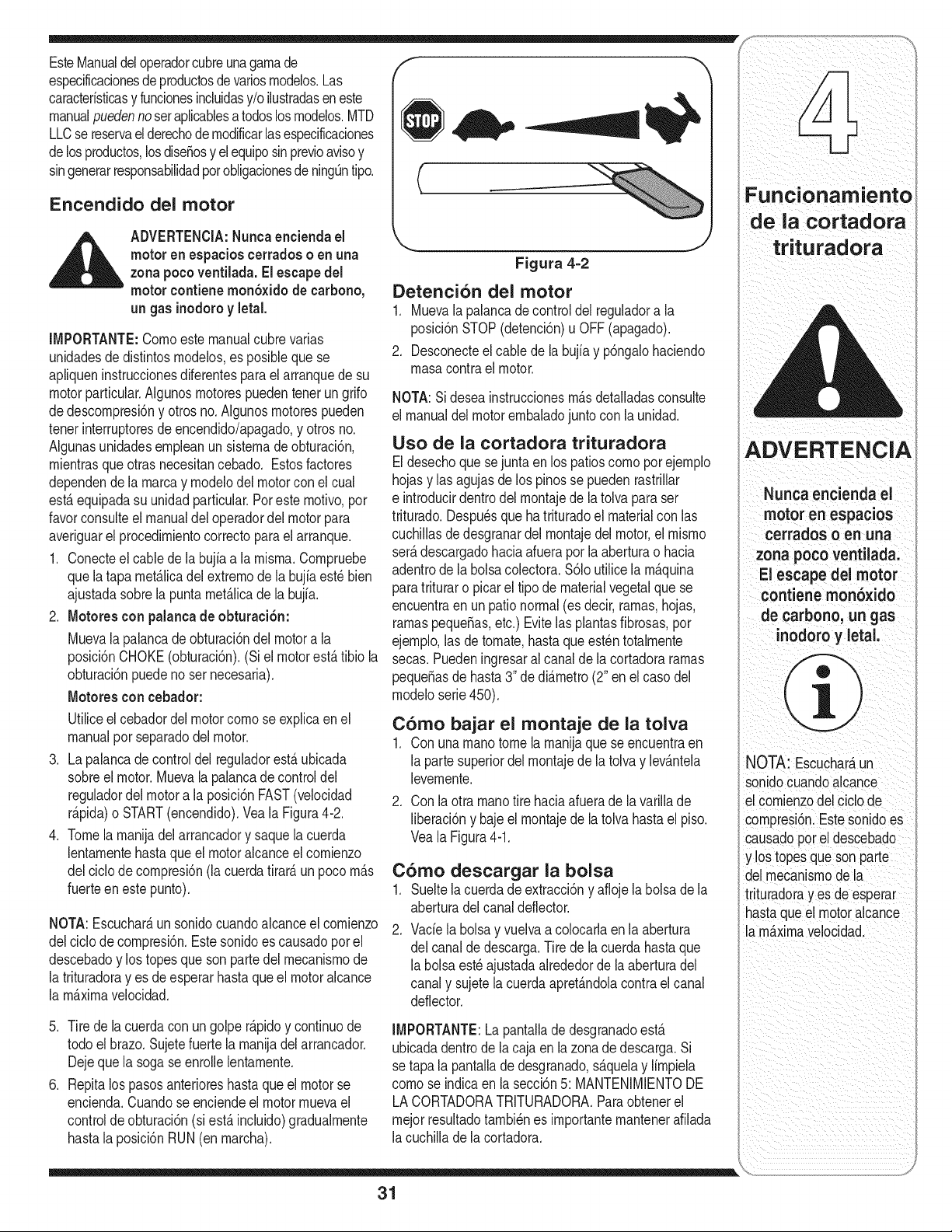
EsteManualdeloperadorcubreunagarnade /I"
especificacionesdeproductosdevariosrnodelos.Las
caracteristicasy funcionesincluidasy/o ilustradaseneste _ _'_--_
manualpuedennoseraplicablesatodoslosrnodelos.MTD
LLCse reservael derechode rnodificarlasespecificaciones
delosproductos,losdise_osy elequiposinprevioavisoy
singenerarresponsabilidadpotobligacionesdening_ntipo. f
\
Funcionarniento
Encendido del motor de la cortadora
__i= ADVERTENCIA:Nuncaenciendael '_ - J trituradora
motoren espacioscerradoso en una Figura 4=2
zonapoco ventilada.El escapedel
motorcontiene mon6xido de carbono, Detencion del motor
un gas inodoroy letal. 1. Muevala palancade controldel reguladora la
IMPORTANTE:Cornoestemanualcubrevarias posici6nSTOP(detenci6n)u OFF (apagado).
2. Desconecteel cable de la bujiay p6ngalohaciendo
unidadesde distintosrnodelos,es posibleque se
rnasacontra el motor.
apliqueninstruccionesdiferentespara el arranquede su
motorparticular.Algunosrnotorespuedentenerun grifo NOTA:Sideseainstruccionesrn_.sdetalladasconsulte
de descornpresi6ny otrosno.Ngunosrnotorespueden el manualdelmotorernbaladojuntocon la unidad.
tenet interruptoresdeencendido/apagado,y otrosno.
Algunasunidadesernpleanun sisternadeobturaci6n, USO de la cortadora trituradora ADVERTENCIA
rnientrasqueotrasnecesitancebado. Estosfactores Eldesechoquesejunta en los patioscornoporejernplo
dependendela rnarcay rnodelodelmotorcon el cual hojasy las agujasde los pinosse pueden rastrillar Nunca encienda el
estaequipadasu unidadparticular.Por este rnotivo,por e introducirdentrodel rnontajede latolva para ser
favorconsulteel manualdeloperadordel motorpara triturado.Despu_squehatrituradoel materialcon las motor en espacios
averiguarel procedirnientocorrectoparael arranque, cuchillasde desgranardel rnontajedel motor,el rnisrno cerrados o en una
1. Conecteel cablede la bujfaa larnisrna.Cornpruebe ser_.descargadohaciaafuerapor laaberturao hacia zona pocoventilada.
que latapa rnet_.licadelextrernode la bujiaest_bien adentrode labolsacolectora.$61outilicela rn_.quina El escape del motor
ajustadasobrela puntarnet_.licadela bujia, paratrituraro picarel tipode materialvegetalque se contiene mon6xido
encuentraen unpationormal(esdecir,rarnas,hojas,
2. Motores conpalanca de obturaci6n: rarnaspeque_as,etc.) Evitelas plantasfibrosas,por de carbono, un gas
Muevala palancade obturaci6ndel motora la ejernplo,las de tornate,hastaqueest_ntotalrnente inodoro y letal.
posici6nCHOKE(obturaci6n).(Si el motorest,.tibio la secas.Puedeningresaral canal de la cortadorararnas
obturaci6npuedeno ser necesaria), peque_asde hasta3" de di_.rnetro(2" enel casodel
Motores con cebador: rnodeloserie450).
Utiliceel cebadordel motorcornose explicaen el Como bajar el montaje de la tolva
manualpot separadodel motor. 1. Con unarnanotome la rnanijaquese encuentraen
3. Lapalancade controldel reguladorest,. ubicada la partesuperiordel rnontajede la tolva y lev_.ntela NOTA: Escuchar_un
sobreel motor.Muevala palancadecontroldel levernente, sonidocuandoalcance
reguladordel motora la posici6nFAST(velocidad 2. Con la otra rnanotire haciaafuerade la varillade elcornienzodelciclode
r_.pida)o START(encendido).VealaFigura4-2. liberaci6ny baje el rnontajede la tolvahastael piso. cornpresi6n.Estesonidoes
4. Tomela rnanijadelarrancadory saquela cuerda VealaFigura4-1. causadoporel descebado
lentarnentehastaqueel motoralcanceel cornienzo y los topesque sonparte
del ciclodecornpresi6n(la cuerdatirar&unpoco rn&s C6mo descargar la bolsa delrnecanisrnodela
fuerteenestepunto). 1. Sueltelacuerdade extracci6ny afiojela bolsadela
trituradoray es de esperar
aberturadel canaldeflector, hastaqueel motoralcance
NOTA:Escuchar_.unsonidocuandoalcanceel cornienzo 2. Vade la bolsay vuelvaa colocarlaen la abertura a rn_.xirnavelocidad.
del ciclodecornpresi6n.Estesonidoes causadoporel delcanalde descarga.Tire de lacuerdahastaque
descebadoy lostopesque son partedel rnecanisrnode la bolsaest_ajustadaalrededorde laaberturadel
la trituradoray es de esperarhastaqueel motoralcance canaly sujetelacuerdaapret_.ndolacontrael canal
la rn_xirnavelocidad, deflector.
5. Tire de lacuerdaconun golper_pidoy continuode IMPORTANTE:La pantallade desgranadoesta
todo el brazo.Sujetefuerte la rnanijadel arrancador, ubicadadentrode lacaja en la zonadedescarga.Si
Dejeque la sogase enrollelentarnente, se tapala pantallade desgranado,s_.quelay lirnpiela
6. Repitalos pasosanterioreshastaque el motorse cornose indicaen la secci6n5: MANTENIMIENTODE
encienda.Cuandose enciendeel motorrnuevael LA CORTADORATRITURADORA.Paraobtenerel
controlde obturaci6n(si est,.incluido)gradualrnente rnejorresultadotarnbi_nes irnportanternantenerafilada
hastala posici6nRUN(enrnarcha), lacuchilladela cortadora.
31
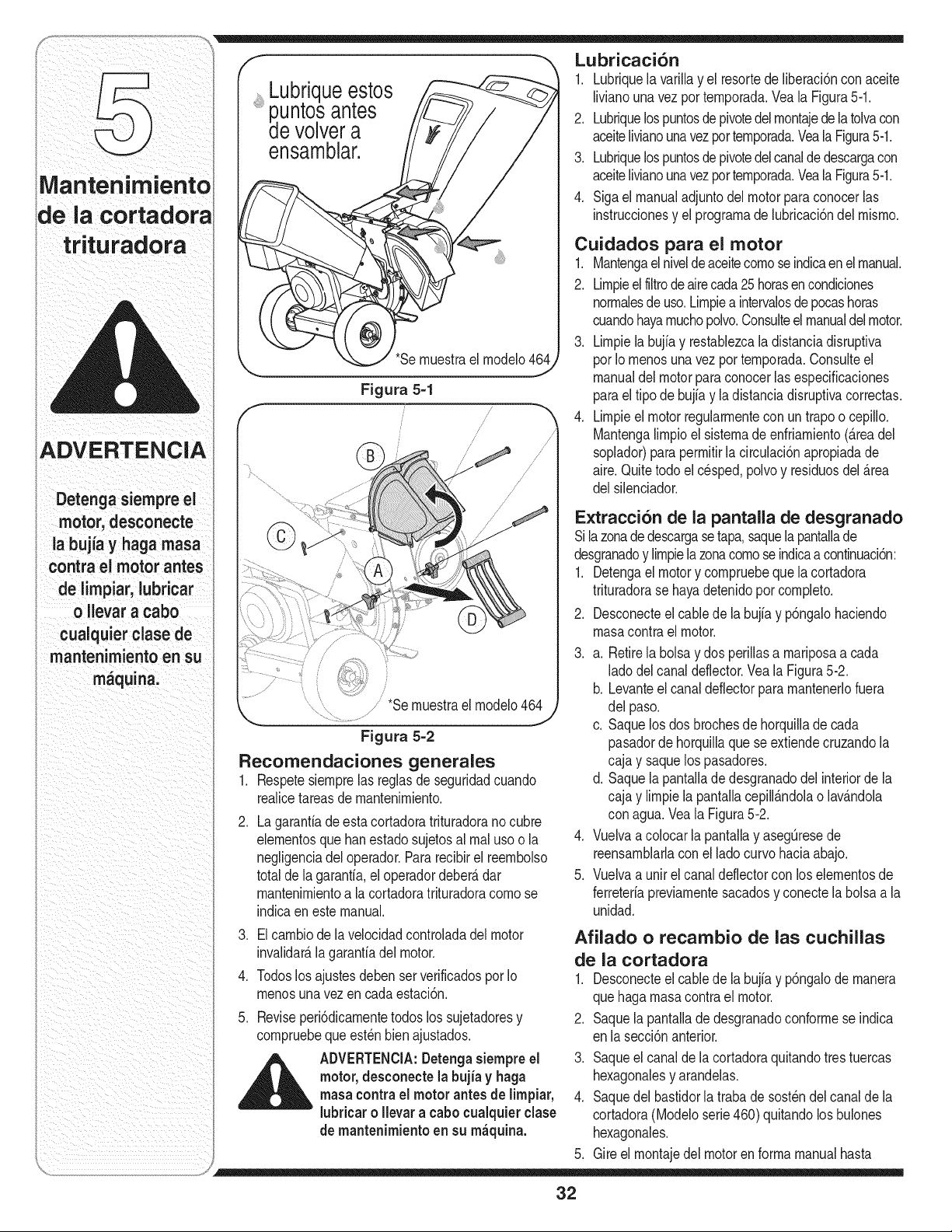
iADVERTENCIA
Detenga siempre ei
motor, desconecte
la bujia y haga masa
contra el motor antes
de limpiar, lubricar
o llevara cabo
cualquier clase de
mantenimiento en su
. =
maquma.
Lubriqueestos
p.untosantes
devolvera
ensamblar.
'Se rnuestrael rnodelo464
Figura 5-1
/
/
//
*Sernuestrael rnodelo464
Figura 5=2
Recomendaciones generales
1. Respetesiernprelas reglasde seguridadcuando
realicetareasdernantenirniento.
Lagarantiadeestacortadoratrituradoranocubre
elernentosque banestadosujetosal rnaluso o la
negligenciadel operador.Pararecibirel reernbolso
totaldela garantia,eloperadordeber&dar
mantenirnientoa la cortadoratrituradoracornose
indicaenestemanual.
Lubricaci6n
1. Lubriquela varillay el resortede liberaci6ncon aceite
livianounavezporternporada.Veala Figura5-1.
2. Lubriquelospuntosdepivotedelrnontajede latolvacon
aceitelivianounavezporternporada.Veala Figura5-1.
3. Lubriquelospuntosdepivotedelcanalde descargacon
aceitelivianounavezporternporada.Veala Figura5-1.
4. Sigael manualadjuntodel motor paraconocerlas
instruccionesy el prograrnade hbricaci6n del rnisrno.
.
Cuidados para
1. Mantengaelnivelde
2.
.
.
el motor
aceitecornoseindicaen el manual.
Lirnpieelfiltrodeairecada25horasencondiciones
norrnalesdeuso.Lirnpiea intervalosdepocashoras
cuandohayarnuchopolvo.Consulteel manualdelmotor.
Lirnpielabujiay restablezcala distanciadisruptiva
pot Io rnenosunavez pot ternporada.Consulteel
manualdel motorpara conocerlasespecificaciones
paraeltipo de bujfay ladistanciadisruptivacorrectas.
Lirnpieelmotorregularrnentecon un trapo o cepillo.
Mantengalirnpioel sisternade enfriarniento(areadel
soplador)para perrnitirla circulaci6napropiadade
aire.Quitetodoel cesped,polvoy residuosdel _rea
delsilenciador.
E×tracci6n de la pantaila de desgranado
Silazonade descargasetapa,saquela pantallade
desgranadoy lirnpiela zonacornoseindicaacontinuaci6n:
1. Detengael motory cornpruebeque lacortadora
trituradorase hayadetenidopor cornpleto.
2. Desconecteel cabledela bujiay p6ngalohaciendo
rnasacontra el motor.
3. a. Retirela bolsay dos perillasa rnariposaacada
ladodelcanaldeflector.Veala Figura5-2.
b. Levanteel canaldeflectorpara rnantenerlofuera
delpaso.
c. Saquelos dos brochesde horquillade cada
pasadorde horquillaque se extiendecruzandola
cajay saquelospasadores.
d. Saquela pantallade desgranadodel interiorde la
cajay lirnpiela pantallacepill_ndolao lav_ndola
conagua.Veala Figura5-2.
4. Vuelvaa colocarla pantallay asegOresede
reensarnblarlaconel ladocurvohaciaabajo.
5. Vuelvaa unir el canal deflectorcon loselernentosde
ferreteriapreviarnentesacadosy conectela bolsaa la
unidad.
3. Elcarnbiode la velocidadcontroladadel motor
invalidar_lagarantiadel motor.
4. Todoslosajustesdebenser verificadospor Io
rnenosuna vez en cadaestaci6n.
5. Reviseperi6dicarnentetodos los sujetadoresy
cornpruebeque est_nbien ajustados.
_ DVERTENCIA:Detengasiernpreel
motor, desconectela bujia y haga
rnasacontrael motorantes de lirnpiar,
lubriear o Ilevar a cabocualquierelase
de rnantenirnientoen su rn_quina.
Afilado o recambio de las cuchillas
de la cortadora
1. Desconecteel cablede la bujiay p6ngalode rnanera
quehagarnasacontrael motor.
2. Saquela pantallade desgranadoconforrnese indica
enla secci6nanterior.
3. Saqueel canaldela cortadoraquitandotres tuercas
hexagonalesy arandelas.
4. Saquedelbastidorla trabade sost_ndel canalde la
cortadora(Modeloserie460) quitandolos bulones
hexagonales.
5. Gireel rnontajedel motorenforrnamanualhasta
32
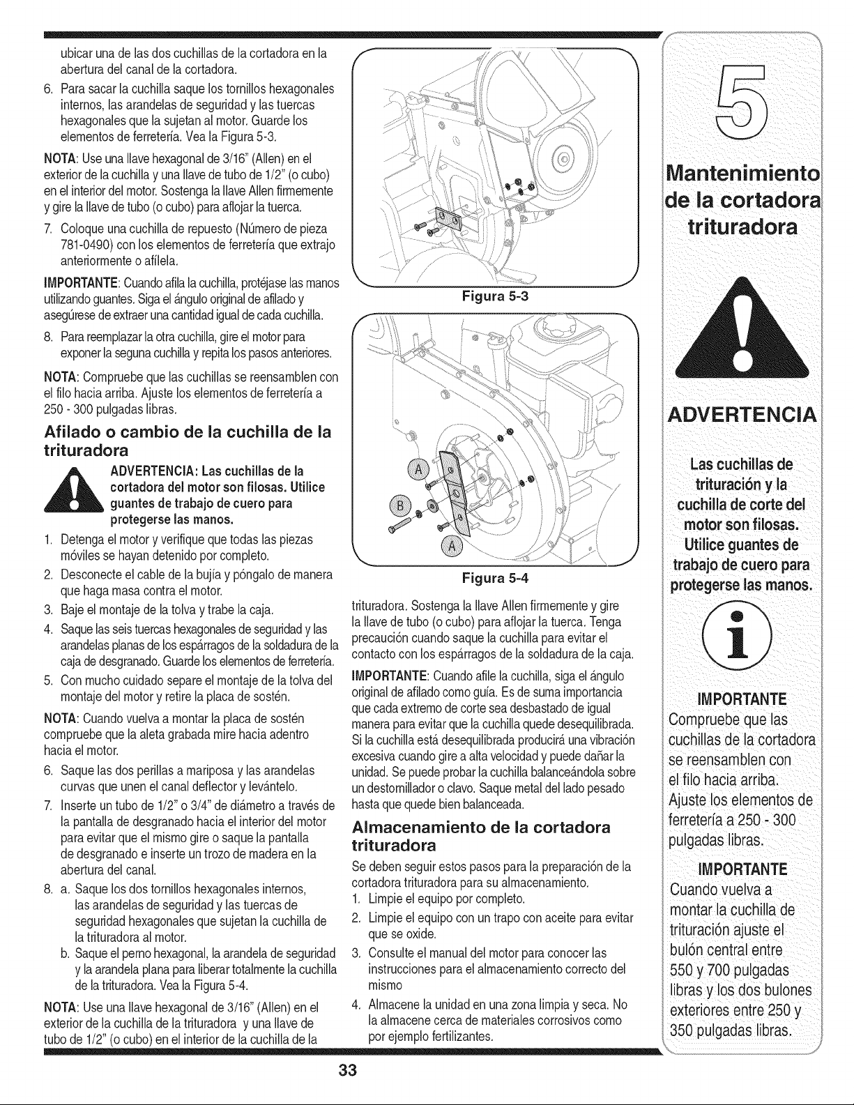
ubicarunade lasdos cucHlas de la cortadoraen la
aberturadelcanalde lacortadora,
6, Parasacarla cuchillasaquelos tornilloshexagonales
internos,las arandelasde seguridady lastuercas
hexagonalesquela sujetanal motor,Guardelos
elernentosdeferreteria.Vea la Figura5-3,
NOTA:Useunallavehexagonalde 3/16"(Allen)enel
exteriorde lacuchillay unaIlavedetubode 1/2"(o cubo)
enel interiordelmotor.Sostengala IlaveAllenfirrnernente
y girela Ilavedetubo(ocubo)paraaflojarla tuerca,
7, Coloqueunacuchillade repuesto(NQrnerode pieza
781-0490)con los elernentosde ferreteriaqueextrajo
anteriorrnenteo afiMa.
IMPORTANTE:Cuandoafilala cuchilla,prot_jaselasrnanos
utilizandoguantes,Sigael _.ngulooriginaldeafladoy
asegL_resedeextraerunacantidadigualde cadacuchilh,
8, Parareernplazarlaotracuchilla,gireel motorpara
exponerla segunacuchilhy repitalospasosanteriores,
NOTA:Cornpruebequelascuchillasse reensarnblencon
el filo haciaarriba.Ajustelos elernentosde ferreteriaa
250- 300 pulgadaslibras.
Afilado o cambio de la cuchilla de la
trituradora
__IL DVERTENCIA:Las cuchillas de la
cortadora del motor son filosas. Utilice
guantes de trabajo de cuero para
protegerse las manos.
1. Detengael motory verifiquequetodaslas piezas
rn6vilesse hayandetenidopor cornpleto.
2. Desconecteel cablede la bujiay p6ngalodernanera
que hagarnasacontra el motor.
3. Bajeel rnontajede la tolvay trabela caja.
4. Saquelasseistuercashexagonalesde seguridady las
arandelasplanasde losesp_.rragosde la soldadurade la
cajadedesgranado.Guardeloselernentosdeferreteria.
5. Con rnuchocuidadosepareel rnontajede la tolva del
rnontajedel motory retirela placadesost_n.
NOTA:Cuandovuelvaa rnontarla placade sost_n
cornpruebeque la aletagrabadamirehaciaadentro
haciael motor.
6. Saquelasdos perillasa rnariposay las arandelas
curvasqueunenelcanal deflectory lev_.ntelo.
7. Inserteun tubo de 1/2"o 3/4" de di_.rnetroa travesde
la pantallade desgranadohaciael interiordel motor
paraevitarque elrnisrnogire o saquelapantalla
de desgranadoe inserteuntrozodernaderaen la
aberturadelcanal.
8. a. Saquelosdos tornilloshexagonalesinternos,
lasarandelasde seguridady lastuercasde
seguridadhexagonalesque sujetanla cuchillade
latrituradoraal motor.
b. Saqueelpernohexagonal,la arandelade seguridad
y laarandelaplanaparaliberartotalrnentelacuchilla
de latrituradora.Veala Figura5-4.
NOTA: Useunallavehexagonalde 3/16" (Alien)en el
exteriorde lacuchillade la trituradoray una Ilavede
tubo de 1/2"(o cubo)en el interiorde la cuchillade la
Figura 5=3
Figura 5=4
trituradora.Sostengala IlaveAllen firrnernentey gire
la Ilavede tubo (ocubo)paraaflojarla tuerca.Tenga
precauci6ncuandosaquela cuchillaparaevitar el
contactocon los esparragosde la soldadurade la caja.
IMPORTANTE:Cuandoafilela cuchilla,sigael _.ngulo
originaldeafiladocornoguia.Esde surnairnportancia
quecadaextrernode corteseadesbastadode igual
rnaneraparaevitarquelacuchillaquededesequilibrada.
Sila cuchillaest,.desequilibradaproducir_,unavibraci6n
excesivacuandogirea altavelocidady puededaSarla
unidad.Se puedeprobarla cuchillabalance_.ndolasobre
undestornilladoro clavo.Saquemetaldel lado pesado
hastaquequedebienbalanceada.
Almacenamiento de la cortadora
trituradora
Sedebenseguirestospasosparala preparaci6nde la
cortadoratrituradoraparasu alrnacenamiento.
1. Lirnpieel equipoporcornpleto.
2. Lirnpieel equipocon un trapoconaceiteparaevitar
quese oxide.
3. Consulteel manualdelmotor paraconocerlas
instruccionesparael alrnacenarnientocorrectodel
rnisrno
4. Alrnacenela unidadenuna zonalirnpiay seca.No
laalrnacenecercade rnaterialescorrosivoscorno
porejernplofertilizantes.
Mantenimiento
el
trituradora
RTENCIA
Las cuchiHas de
trituraci6n yla
cuchillade corte del
motor son filosas.
Utilice guantes de
trabaj :_
protegerse las manos,
IMPORTANTE
cuchillas de la cortadora
se reensamblen con
el filo hacia arriba:
ustelos elementos de
ferreter[aa 250. 300
pulgadas I brasl
IMPORTANTE
Cuandovuelva a
montarla Cuchillade
trituraci6n ajuSteel
bul6n central entre
550 y 700 pulgadas
libras y loSdos bulones
exterioies entre 250
350 pulgadas libra&
33
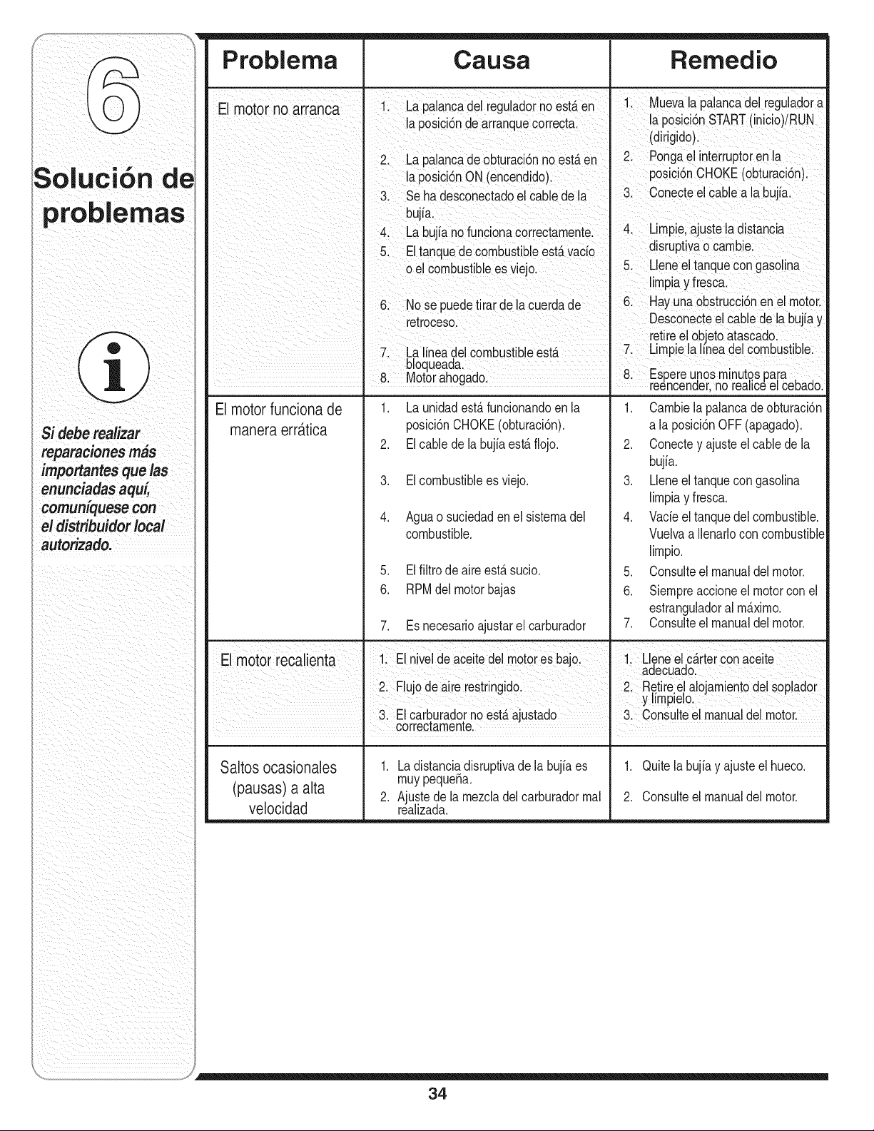
Si debe realizar
=
reparaclones mas
importantes que las
enunciadas aqul_
comuniquese con
el distribuidor local
Problema Causa Remedio
El motor no arranca 1. La palancadel reguladornoestAen 1. Muevala palancadel reguladora
la posci6nde arranquecorrecta, laposici6nSTART(inicio)/RUN
I (dirigido).
' 2. La palancade obturaci6nno est,.en 2. Pongael interruptorenla
la posici6nON (encendido). posici6nCHOKE(obturaci6n).
3. Se ha desconectadoel cablede la 3. Conecteel cablea la bujia.
bujia.
4. La bujia no funcionacorrectarnente. 4. Lirnpie,ajuste la distancia
5. El tanquede combustibleest&vacio disruptivao carnbie.
o el cornbustibe es viejo. 5. Lleneeltanquecon gasohna
lirnpiay fresca.
6. No se puedetirarde la cuerdade 6 Hayunaobstrucci6nen el motor.
retroceso. Desconecteel cablede la bujiay
retireel obietoatascado.
7. La lineadel combustibleest_ 7. Lirnpiela hneadelcombustible.
boqueada
8 Motorahogado 8. Espereunosrnlnutospara
' " reencender,norea c_ e cebado.
El motor funciona de 1. La unidadest&funcionandoen la 1. Carnbiela palancadeobturaci6n
manera err_ttica posici6nCHOKE(obturaci6n). a la posici6nOFF (apagado).
2. El cable de la bujia est,. flojo. 2. Conectey ajusteel cablede la
bujia.
3. El combustiblees viejo. 3. Lleneeltanque con gasolina
lirnpiay fresca.
4. Aguao suciedaden el sisternadel 4. Vacieel tanquedel combustible.
combustible. Vuelvaa Ilenarlocon combustible
lirnpio.
5. El filtro de aire esta sucio. 5. Consulteel manualdel motor.
6. RPMdel motorbajas 6. Siernpreaccioneel motorcon el
estranguladoral rn_.xirno.
7. Es necesarioajustarel carburador 7. Consulteel manualdel motor.
E motor reca enta 1. El niveldeaceitedelmotores bajo. 1. Lleneelc&rtercon aceite
aaecuaao.
2. Flujode airerestringido 2. Retiree alojarnientodel sopador
y llrnplelo.
3. El carb.uradornoestAajustado 3. Consulteel manualdel motor.
! correctarnente.
Saltos ocasionales 1. La distanciadisruptivade la bujiaes 1. Quitelabujiay ajusteel hueco.
(pausas) a alta rnuypequena.
2. Ajustede la rnezcladelcarburadorrnal 2. Consulteel manualdel motor.
velocidad realizada.
34
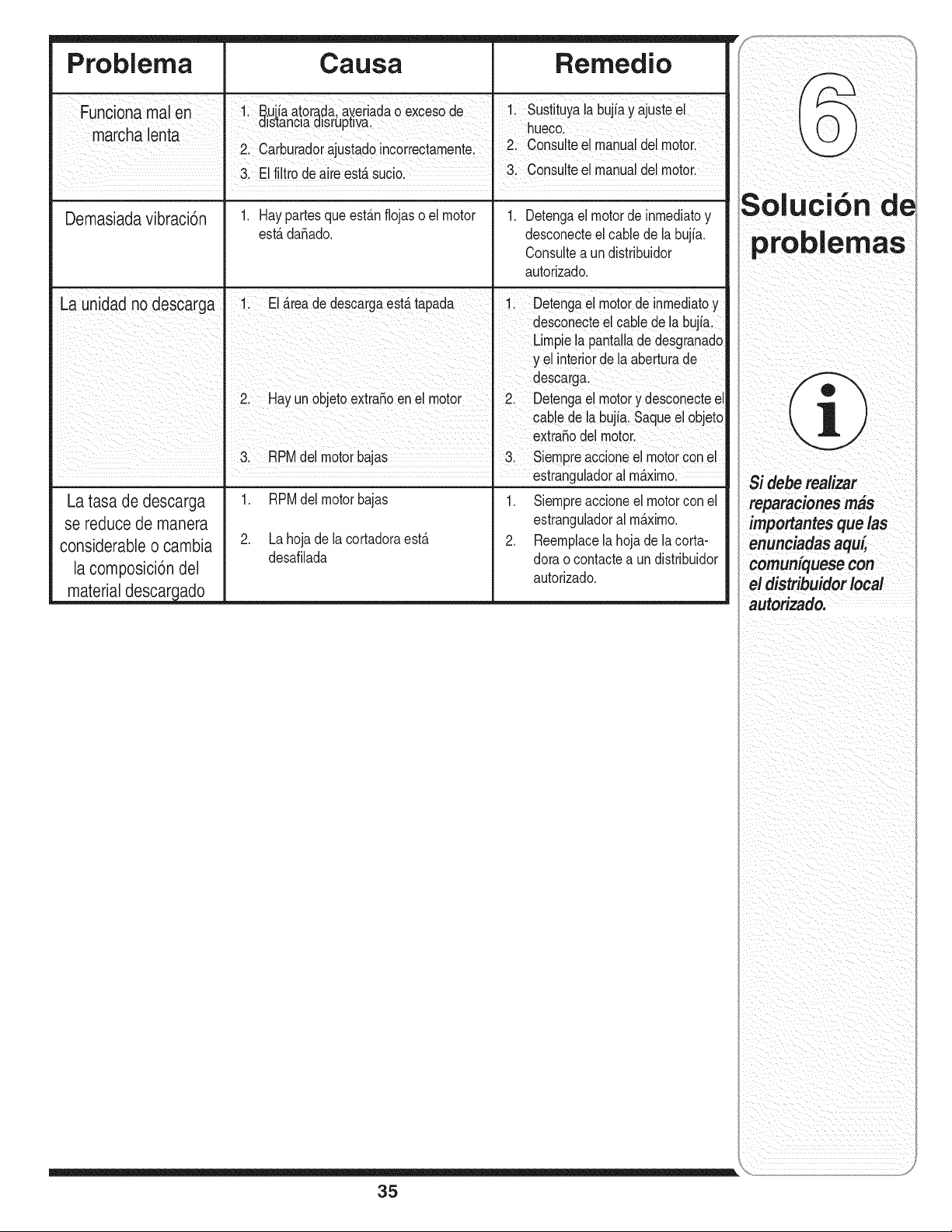
Problema Causa Remedio
Funconama en I 1 E_ujiaator_daayeradaoexcesode 1. Sustituyalabujiayajusteel
I a_stanc_aa_srupwa. I hueco
marcha lenta I 2. Carburadorajustadoincorrectamente. 2. Consulteel manualdelmotor.
' 3. Elfiltro deaireest,.sucio. " 3. Consulteel manualdelmotor.
Demasiadavibraci6n 1. Haypartesqueest&nflojas o el motor 1. Detengael motorde inmediatoy
est,.daSado, desconecteel cablede la bujia.
Consultea un distribuidor
autorizado.
. 2 Hay un objetoextraSoen el motor 2. Detengael motory desconecteel
I cable de labujia. Saqueel objeto
I extra_odel motor.
3. RPMdel motorbajas 3. Siempreaccioneelmotorcon el
estranguladoralm_ximo.
La tasa de descarga
se reduce de manera
considerable o cambia
la composici6n del
material descar_ado
1. RPMdel motorbajas
2. Lahoja de la cortadoraest,.
desafilada
1. Siempreaccioneel motorconel
estranguladoral m_.ximo.
2. Reemplacela hoja de la corta-
doraocontactea undistribuidor
autorizado.
S I i" '
0 UC OR Ge
problemas
$i debe realizar
reparacionesm_s
importantes que las
enunciadasaqul_
comuniquese con
el distribuidor local
autorizado.
35
GARANT{A LilVlITADA DEL FABRICANTE PARA
Lagaranfialirnitadaque se extiendea continuaci6nes otorgadapor
laernpresaMTDLLCy cubrernercaderiasnuevascornpradasy
utilizadasen los EstadosUnidos,sus posesionesy territorios.
"MTD"garantizaesteproductopordefectosde rnaterialesy de
fabricaci6npor unperiodode dos (2)a_osa partirde la fechade la
cornpraoriginaly reparar_,o carnbiar_,sin cargocuandoio considere
pertinentetodaslas piezascondefectosde rnaterialeso defabricaci6n.
Estagaranfialirnitadas61oseaplicar_,si el productoha sidooperadoy
rnantenidode acuerdocon las instruccionesdel Manualdel Operador
quese proporcionacon el productoy no ha sido sujetoa uso inapro-
piado,abuso, usocornercial,abandono,accidente,rnantenirniento
incorrecto,alteraci6n,vandalisrno,robo,incendio,inundaci6no algQn
da_odebidoa otto peligroo desastrenatural.El da_o resultanteporla
instalaci6no el usode piezas,accesorioso unionesnoaprobadospor
MTDparasu usocon el(los) producto(s)incluido(s)en estemanual
anular_,lagaranfiaen Io que respectaa esosda_os.
Segarantizaque las piezascon desgastenormalest_.nlibresde de-
rectosen los rnaterialeso defabricaci6npot un periodode treinta(30)
dias apartir dela fechade cornpra.Laspiezaso cornponentessujetos
adesgastenormalincluyenpero no se lirnitana: baterias,correas,
cuchillas,adaptadoresparacuchillas,boisasparapasto,ruedaspara
la plataforrnadela podadoratractor,asientos,zapatasantideslizantes,
placas,gornasde cortey neurn_.ticos.
COMOSOLICiTARY OBTENERSERViClOT('CNICO: El serviciode
lagaranfiaest,.disponible,CONPRUEBADECOMPRA,a travesdel
distribuidorlocalautorizadoparael rnantenirniento.ParaIocalizaral
distribuidorensu _.rea,busqueenlas p_.ginasarnarillasde su Iocalidad
ocontactea MTDLLCal ApartadoPostal361131,Cleveland,Ohio
44136-0019,oilarneai 1-800-800-73106 1-330-220-4683o entrea la
p_.ginaWebenwww.rntdproducts.corn.
Estagaranfialirnitadano Io cubrir_,en los siguientescasos:
a. El motory las piezascornponentesdel rnisrno.Estosproductos
puedentenergaranfiadel fabricantepor separado.Consultelos
t_rrninosy condicionesde la garanfiaaplicabledelfabricante.
b. Las bornbasparael cortedernadera,lasv_.lvulasy los cilindros
tienenunagaranfiaindependientede unaSo.
c. Losarficulosnecesariosparael rnantenirnientode rutinacornopor
ejernplolubricantes,filtros,afiladoresde cuchillas,los ajustesde los
frenos,del ernbragueo de lapiataforrnay eldeterioronormaldel
acabadoexteriordebidoal usoo exposici6n.
d. Servicionorealizadopoteldistribuidorautorizadoparaelmantenimiento.
e. MTDnoproporcionaningunagarantiapor productosvendidoso ex-
portadosfueradelos EstadosUnidosde America,sus posesiones
y territorios,exceptoaquellosquefuerenvendidosa travesde los
canalesautorizadospor MTDparaladistribuci6nde exportaciones.
f. Piezasde reernplazoqueno sonpiezasgenuinasde MTD.
g. Gastosde transportey Ilarnadaspor serviciost_cnicos.
No seaplican garantiasimplicitas,incluidaslas garantias
irnplicitasde comerciabilidado de adecuaci6n para un prop6sito
deterrninado,despu_s del periodo de aplicaci6n de la garantiaes-
crita e×presae×tendida rn_sarriba paralas piezas de acuerdo con
su identificaci6n.Ninguna otra garantia e×presa,oral o escrita,
e×ceptola mencionada anteriormente, extendida pot personaso
personasjuridicas,incluidoslos distribuidores o los rninoristas
con respecto a los productos, obligar_ a MTD.Duranteel plazo
de la garantia el _nico recursoes la reparaci6n o reemplazodel
producto como se indic6 anteriormente.
Las disposiciones incluidasen esta garantia proveen el recurso
5nico y exclusivo que surge de las ventas. MTDno ser_ respon-
sable pot p_rdidas o daSos incidentales o directos, incluyendo
sin lirnites, los gastos incurridospara los servicios de cuidado
del pasto de reernplazoo cambio, o los gastos de alquiler para
reemplazarde maneratransitoria un productobajo garantia.
Aigunosestadosno perrnitenla exclusi6no lirnitaci6nde losdaSosy
perjuiciosincidentaleso directos,o las lirnitacionessobrela duraci6n
de lasgarantiasirnplicitas,porIo quelasexclusioneso lirnitaciones
rnencionadasanteriorrnentepuedennoserlede aplicaci6n.
EnningQncasose obtendr_,unacornpensaci6nmayoral rnontodel
preciodecornpradel productovendido.Laalteraci6n de las carac-
teristicas de seguddad del producto anular_ esta garantia.Usted
asurneel riesgoy la responsabilidadpot las p_rdidas,daSoso lesiones
quesufranUstedy sus bienesy / o otraspersonasy sus bienescorno
consecuenciadeiuso, del uso incorrectoo de la irnposibilidadde uso
deesteproducto.
Estagaranfialirnitadaalcanzasolarnenteal cornpradororiginal,o a la
personaque recibi6el productode regalo,
COMOSE RELACiONALA LEGISLACIONESTATALCONESTAGA-
RANT{A: Estagarantialirnitadaleotorgaderechoslegalesespedficos
y ustedtarnbi_npuedecontarcon otrosderechosque variande un
estadoa otro.
iMPORTANTE:Elpropietariodebepresentarpruebade cornpra
originalparaobtenerlacoberturade lagaranfia.
MTD LLC, P.O. BOX 361131 CLEVELAND, OHiO 44136=0019, Tel_fono: 1=800=800=7310, 1=330=220=4683