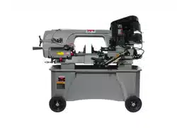
Operating Instructions and Parts Manual
Horizontal-Vertical Band Saw
Models HVBS-712, HVBS-712D
JET
427 New Sanford Road
LaVergne, Tennessee 37086 Part No. M-414559
Ph.: 800-274-6848 Edition 8 03/2022
www.jettools.com Copyright © 2022 JET
HVBS-712D Deluxe model shown
This .pdf document is bookmarked.

1.0 IMPORTANT SAFETY
INSTRUCTIONS
Read and understand the entire instruction
manual before operating machine.
This band saw is designed and intended for use
by properly trained and experienced personnel
only. If you are not familiar with the proper and
safe operation of a band saw, do not use until
proper training and knowledge have been
obtained.
WARNING – To reduce risk of injury:
Read and understand the warnings posted on the
machine and in this manual. Failure to comply with
all of these warnings may cause serious injury.
Replace warning labels if they become obscured or
removed.
Do not use this band saw for other than its intended
use. If used for other purposes, JET disclaims any
real or implied warranty and holds itself harmless
from any injury that may result from that use.
Always wear ANSI Z87.1 approved safety glasses
or face shield while using this band saw. (Everyday
eyeglasses only have impact resistant lenses; they
are not safety glasses.)
Before operating this machine, remove tie, rings,
watches and other jewelry, and roll sleeves up past
the elbows. Do not wear loose clothing. Confine long
hair. Non-slip footwear or anti-skid floor strips are
recommended. Do not wear gloves.
Wear hearing protection (plugs or muffs) during
extended periods of operation.
Do not operate this machine while tired or under the
influence of drugs, alcohol or any medication.
Reduce the risk of unintentional starting. Make sure
switch is in off position before plugging in.
Make certain the machine is properly grounded.
Make all machine adjustments or maintenance with
the machine unplugged from the power source.
Remove adjusting keys and wrenches. Form a habit
of checking to see that keys and adjusting wrenches
are removed from the machine before turning it on.
Keep safety guards in place at all times when the
machine is in use. If removed for maintenance
purposes, use extreme caution and replace the
guards immediately after completion of
maintenance.
Check damaged parts. Before further use of the
machine, a guard or other part that is damaged
should be carefully checked to determine that it will
operate properly and perform its intended function.
Check for alignment of moving parts, binding of
moving parts, breakage of parts, mounting and any
other conditions that may affect its operation. A
guard or other part that is damaged should be
properly repaired or replaced.
Provide for adequate space surrounding work area
and non-glare, overhead lighting.
Keep work area clean. Keep floor around the
machine free of scrap material, oil and grease.
Cluttered areas and benches invite accidents.
Keep visitors a safe distance from the work area.
Keep children away.
Make your workshop child-proof with padlocks,
master switches or by removing starter keys.
Give your work undivided attention. Looking around,
carrying on a conversation and “horse-play” are
careless acts that can result in serious injury.
Maintain a balanced stance at all times so that you
do not fall into the blade or other moving parts. Do
not overreach or use excessive force to perform any
machine operation.
Use the right tool at the correct speed and feed rate.
Do not force a tool or attachment to do a job for
which it was not designed. The right tool will do the
job better and more safely.
Use recommended accessories; improper
accessories may be hazardous.
Maintain tools with care. Keep saw blades sharp
and clean for the best and safest performance.
Follow instructions for lubricating and changing
accessories.
Turn off the machine before cleaning. Use a brush
to remove chips or debris — do not use your hands.
Do not stand on the machine. Serious injury could
occur if the machine tips over, or if the cutting tool is
unintentionally contacted.
Never leave the machine running unattended. Turn
the power off and do not leave the machine until it
comes to a complete stop.
Remove loose items and unnecessary workpieces
from the area before starting the machine.
Make sure workpiece is securely clamped in vise.
Never use your hand to hold the workpiece.
Never reach around or over a moving saw blade.
Do not remove jammed cutoff pieces until blade has
stopped.
Feed work into a blade or cutter only against the
direction of rotation of the blade or cutter.
Maintain proper adjustment of blade tension, blade
guides and thrust bearings.
Minimize blade exposure by adjusting blade guides
to just clear workpiece.
Check coolant level daily. Replace dirty or weak
coolant.
Don’t use in dangerous environment. Don’t use
power tools in damp or wet location or expose them
to rain. Keep work area well lighted.
Use proper extension cord. Make sure your
extension cord is in good condition. When using an
3
extension cord, be sure to use one heavy enough to
carry the current your product will draw. An
undersized cord will cause a drop in line voltage
resulting in loss of power and overheating. Table 1
(sect. 6.3) shows correct size to use depending on
cord length and nameplate ampere rating. If in
doubt, use the next heavier gage. The smaller the
gage number, the heavier the cord.
Familiarize yourself with the following safety notices used in this manual:
This means that if precautions are not heeded, it may result in minor injury and/or possible
machine damage.
This means that if precautions are not heeded, it may result in serious, or possibly even fatal,
injury.
SAVE THESE INSTRUCTIONS
2.0 On-off switch padlock
To avoid accidental starting by young children or
others not qualified to use the tool, the use of a
padlock (not provided) is required.
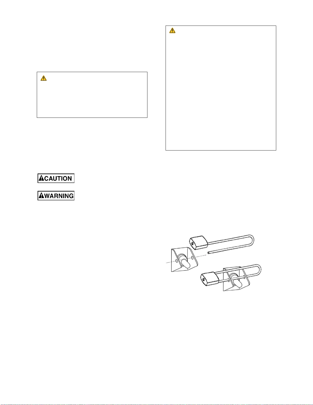
To lock out the on-off switch (Figure 2-1):
1) Open padlock.
2) Insert through hole in switch guard.
3) Close padlock.
4) Store key in a safe place out of the reach of
children.
Figure 2-1
WARNING: This product can expose you to
chemicals including titanium dioxide which is
known to the State of California to cause cancer,
and lead which is known to the State of
California to cause cancer and birth defects or
other reproductive harm. For more information
go to http://www.p65warnings.ca.gov.
WARNING: Some dust, fumes and gases
created by power sanding, sawing, grinding,
drilling, welding and other construction activities
contain chemicals known to the State of
California to cause cancer and birth defects or
other reproductive harm. Some examples of
these chemicals are:
• lead from lead based paint
• crystalline silica from bricks, cement and
other masonry products
• arsenic and chromium from chemically
treated lumber
Your risk of exposure varies, depending on how
often you do this type of work. To reduce your
exposure to these chemicals, work in a well-
ventilated area and work with approved safety
equipment, such as dust masks that are
specifically designed to filter out microscopic
particles. For more information go to
http://www.p65warnings.ca.gov/ and http://www.
p65warnings.ca.gov/wood.

4
3.0 Table of contents
Section Page
1.0 IMPORTANT SAFETY INSTRUCTIONS ................................................................................................................. 2
2.0 On-off switch padlock .................................................................................................................................................. 3
3.0 Table of contents ......................................................................................................................................................... 4
4.0 About this manual ........................................................................................................................................................ 5
5.0 Specifications ............................................................................................................................................................... 6
6.0 Setup and assembly .................................................................................................................................................... 8
6.1 Shipping contents .................................................................................................................................................... 8
6.2 Tools required for assembly ................................................................................................................................... 8
6.3 Unpacking and cleanup .......................................................................................................................................... 8
6.4 Assembly .................................................................................................................................................................. 8
6.5 Coolant tank preparation ...................................................................................................................................... 10
7.0 Electrical connections ................................................................................................................................................ 11
7.1 Grounding instructions .......................................................................................................................................... 11
7.2 Voltage conversion ................................................................................................................................................ 11
......................................................................................................................................................................................... 12
7.3 Extension cords ..................................................................................................................................................... 12
8.0 Adjustments ................................................................................................................................................................ 12
8.1 Tools required for adjustments ............................................................................................................................ 12
8.2 Vertical bow position ............................................................................................................................................. 12
8.3 Blade Speed ........................................................................................................................................................... 13
8.4 Blade guides ........................................................................................................................................................... 13
8.5 Blade replacement ................................................................................................................................................. 14
8.6 Blade guide bearings ............................................................................................................................................ 14
8.7 Chip brush .............................................................................................................................................................. 14
8.8 Blade tension .......................................................................................................................................................... 14
8.9 Blade tracking ......................................................................................................................................................... 14
8.10 Test cut to verify adjustment .............................................................................................................................. 15
8.11 Setting feed rate .................................................................................................................................................. 15
8.12 Counterbalance spring ........................................................................................................................................ 16
8.13 Blade-to-table squareness ................................................................................................................................. 16
8.14 Auto shut-off adjustment..................................................................................................................................... 16
8.15 Vise positioning (712D only) .............................................................................................................................. 17
8.16 Vise positioning (712 only) ................................................................................................................................. 17
9.0 Operation .................................................................................................................................................................... 17
9.1 Blade break-in ........................................................................................................................................................ 17
9.2 General operating procedure ............................................................................................................................... 18
9.3 Evaluating cutting efficiency ................................................................................................................................. 18
10.0 User-maintenance ................................................................................................................................................... 18
10.1 Lubrication ............................................................................................................................................................ 19
10.2 Coolant level ......................................................................................................................................................... 19
10.3 Additional servicing ............................................................................................................................................. 19
11.0 Troubleshooting HVBS-712/712D Band Saw ...................................................................................................... 20
11.1 Mechanical and electrical problems .................................................................................................................. 20
11.2 Operational problems .......................................................................................................................................... 21
12.0 Replacement Parts .................................................................................................................................................. 22
12.1.1 HVBS-712/712D Bed and Stand Assembly – Exploded View ................................................................... 23
12.1.2 HVBS-712/712D Bow Assembly – Exploded View ..................................................................................... 24
12.1.3 HVBS-712/712D – Parts List .......................................................................................................................... 25
13.0 Electrical Connections – HVBS-712/712D Band Saw ........................................................................................ 30
14.0 Warranty and service .............................................................................................................................................. 31

5
4.0 About this manual
This manual is provided by JET, covering the safe operation and maintenance procedures for a JET Model
HVBS-712 and HVBS-712D Band Saw. This manual contains instructions on installation, safety precautions,
general operating procedures, maintenance instructions and parts breakdown. Your machine has been designed
and constructed to provide consistent, long-term operation if used in accordance with the instructions as set forth
in this document.
If there are questions or comments, please contact your local supplier or JET. JET can also be reached at our
web site: www.jettools.com.
Retain this manual for future reference. If the machine transfers ownership, the manual should accompany it.
Read and understand the entire contents of this manual before attempting assembly or
operation! Failure to comply may cause serious injury!

6
5.0 Specifications
Model number ................................................................ HVBS-712D .................................................... HVBS-712
Stock number ........................................................................ 414560 ......................................................... 414559
Motor and electricals:
Main motor:
Motor type…………..……………………..…totally enclosed fan cooled, induction, capacitor start ....................
Horsepower ....................................................... 3/4 HP (0.56 kW) ......................................... 3/4 HP (0.56 kW)
Phase ......................................................................................... 1 ................................................................... 1
Voltage ............................................... 115/230V (prewired 115V) ........................... 115/230V (prewired 115V)
Cycle .................................................................................... 60Hz ............................................................. 60Hz
Listed FLA (full load amps) ................................................ 12/6 A ........................................................... 12/6 A
Starting amps ................................................................. 36A/18A ....................................................... 36A/18A
Running amps (no load) ............................................... 9.8A/4.9A ..................................................... 9.8A/4.9A
Start capacitor .................................................. 300MFD 125VAC ......................................... 300MFD 125VAC
Motor speed ................................................................ 1720 RPM .................................................... 1720 RPM
Pump motor:
Horsepower ............................................................. 1/8HP (90W) ................................................ 1/8HP (90W)
Phase/voltage ............................................................................ 1 ................................................................... 1
Voltage ............................................... 120/240V (prewired 120V) ........................... 120/240V (prewired 120V)
Cycle .................................................................................... 60Hz ............................................................. 60Hz
Listed FLA ...................................................................... 0.5/0.2 A ....................................................... 0.5/0.2 A
Pump motor speed ...................................................... 3450 RPM .................................................... 3450 RPM
Capacitor ...................................................................... 1F 400V ..................................................... 1F 400V
Power transfer ..................................................................... v-belt ............................................................ v-belt
On/off switch ...................................................................... toggle ........................................................... toggle
Power cable ..................... 16AWG x 3C, length 6-1/2 ft. (200cm) ......... 16AWG x 3C, length 6-1/2 ft. (200cm)
Power plug installed ............................................................. 120V ............................................................. 120V
Recommended circuit and fuse/breaker size
1
....................... 15A ............................................................... 15A
Capacities:
Round at 90 degrees........................................... 7 in. (177.8mm) ............................................ 7 in. (177.8mm)
Round at 45 degrees.............................................. 5 in. (127mm) ...................................... 4-1/2 in. (114.3mm)
Rectangle at 90 degrees ..................................... 1(H) x 12(W) in. ............................................ 1(H) x 12(W) in.
...................................................................... 2(H) x 11-1/4(W) in. ..................................... 2(H) x 11-1/2(W) in.
............................................................................ 4(H) x 11(W) in. ............................................. 4(H) x 11(W) in
...................................................................... 7(H) x 10-1/4(W) in. ..................................... 7(H) x 10-3/8(W) in.
Rectangle at 45 degrees ....................................... 6(H) x 4(W) in. ................................. 6-1/2(H) x 4-1/2(W) in.
Square at 90 degrees....................................................... 7 x 7 in. ........................................................ 7 x 7 in.
Square at 45 degrees........................................................ 5 x 5 in ............................................. 4-1/2 x 4-1/2 in
Gearbox oil capacity............................................ 3/4 pint (0.35 L) ............................................ 3/4 pint (0.35 L)
Coolant tank capacity ............................................... 2.5 gal. (9 L) ................................................. 2.5 gal. (9 L)
Bow and blade:
Blade type (provided) ............................................. Bi-metal, 5/8T ............................................... Bi-metal, 5/8T
Blade size ...................... 3/4 x 0.035 x 93 in.(19 x 0.9 x 2360mm) ...... 3/4 x 0.035 x 93 in.(19 x 0.9 x 2360mm)
Number of blade speeds ............................................................ 4 ................................................................... 4
Blade speeds ........................................ 86, 132, 178, 260 SFPM .............................. 86, 132, 178, 260 SFPM
Blade wheel diameter.................................. 11-3/4 in. (298.5mm) .................................... 11-3/4 in. (298.5mm)
Gear ratio ........................................................... 1/20 (M2.5x20T) ........................................... 1/20 (M2.5x20T)
Bed and vise:
Bed height from floor (without wheels) ............. 22.4 in. (569mm). .......................................... 22.4 in. (569mm)
Vise swivel ....................................................................... 45 deg. ......................................................... 45 deg.
Vise detents ..................................................... 0, 15, 30, 45 deg. ................................................................ n/a
1
Subject to local/national electrical codes.

7
Main materials:
Bed ........................................................ cast iron, ground surface ............................. cast iron, ground surface
Bow ................................................................................. cast iron ....................................................... cast iron
Stand ..................................................................................... steel ............................................................. steel
Blade drive system……………………….steel, heat-treated worm driving a bronze worm gear in oil bath ........
Side blade guides…………………………………………….ball bearings mounted on eccentric shafts ..............
Rear blade guides .................................................... ball bearings ................................................. ball bearings
Band wheels............................................................. ball bearings ................................................. ball bearings
Dimensions:
Table plate dimensions ...................... 12 x 12 in. (305 x 305mm) ........................... 12 x 12 in. (305 x 305mm)
Overall dimensions, assembled ........................... 48 x 17 x 40 in. ............................................. 48 x 17 x 40 in.
.............................................................. (1219 x 432 x 1016 mm) .............................. (1219 x 432 x 1016 mm)
Overall dimensions, shipping .................. 51.18 x 19.2 x 44.88 in. ................................ 51.18 x 19.2 x 44.88 in.
.............................................................. (1300 x 488 x 1140 mm) .............................. (1300 x 488 x 1140 mm)
Stand wheels.......................................................... 8 in. (203mm) ............................................... 8 in. (203mm)
Weights:
Net weight ......................................................... 374 lbs. (170 kg) .......................................... 374 lbs. (170 kg)
Shipping weight ................................................. 418 lbs. (190 kg) .......................................... 418 lbs. (190 kg)
The specifications in this manual were current at time of publication, but because of our policy of continuous
improvement, JET reserves the right to change specifications at any time and without prior notice, without incurring
obligations.
8
6.0 Setup and assembly
Read and understand all
instructions before attempting assembly. Band
Saw must be disconnected from power during
all assembly procedures. Failure to comply may
cause serious injury.
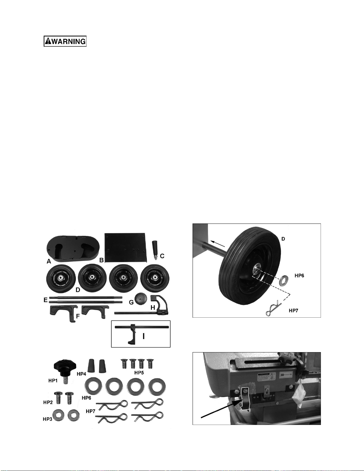
6.1 Shipping contents
See Figures 6-1, 6-2.
1 Band saw (not shown)
1 Pulley cover – A
1 Table Plate – B
1 Handle with washer and nut – C
4 Wheels – D
2 Axles – E
2 Supports (1 long, 1 short) – F (712D only)
1 Filter assembly – G
1 Work stop assembly – H (712D only)
1 Work stop assembly – I (712 only)
1 Hardware package (p/n HVBS712-HP):
1 Lock screw – HP1
2 Hex cap bolts 1/4 x 1/2 – HP2
2 Flat washers 1/4 – HP3
2 Wire nuts – HP4
4 Flat head screws 1/4 x 3/8 – HP5
4 Flat washers 5/8 – HP6
4 Cotter pins – HP7
Figure 6-1: shipping contents
Figure 6-2: hardware package HVBS712-HP
6.2 Tools required for assembly
Wrenches, 10mm and 19mm
#2 cross point screwdriver
Pliers
6.3 Unpacking and cleanup
1. Inspect all contents for shipping damage.
Compare contents of shipping carton with
contents list in this manual. Report any damage
or part shortages to your distributor.
2. Do not discard packing material until saw is
assembled and running properly.
3. Remove rust protectant from exposed surfaces,
such as bed, vise assembly, etc., with a clean
rag and a cleaner/degreaser. Apply a light coat
of oil on these surfaces to inhibit rust.
6.4 Assembly
Note: Most figures in this manual show 712D Deluxe
model. Procedures for 712 basic model will be
identical, except where noted.
1. Remove braces holding saw stand to pallet, and
carefully raise saw from pallet, using properly
rated lifting equipment (hoist or forklift) with
straps placed beneath cast iron portion of saw.
2. Slide axles through holes in stand and install
four wheels with flat washers and cotter pins
(Figure 6-3). Bend ends of cotter pins to secure
wheel, then carefully lower saw to floor.
Figure 6-3: installing wheels
3. Remove shipping bracket (Figure 6-4). Then
reinstall bottom hex nut beneath plate. Retain
shipping bracket in case machine must be
transported in future.
Figure 6-4: shipping bracket removal
9
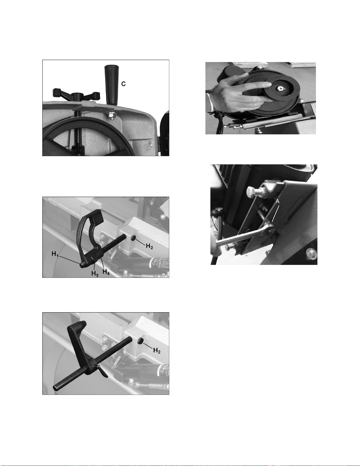
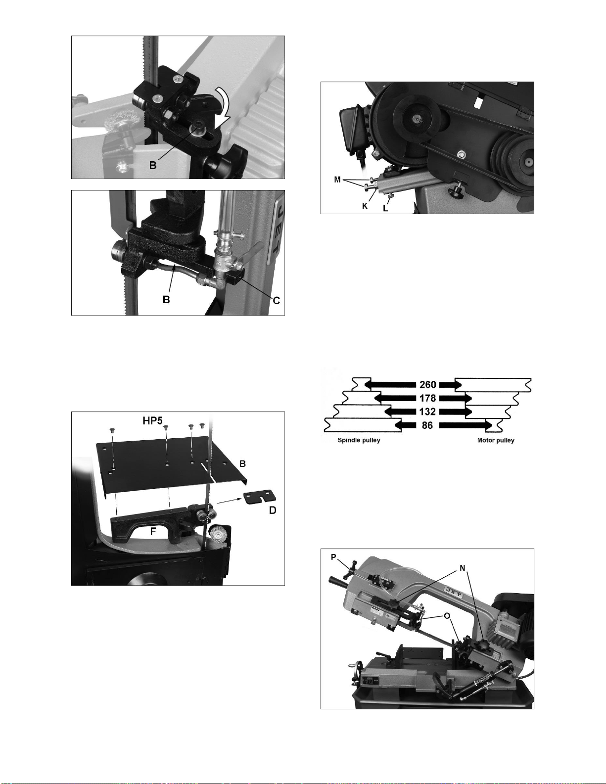
4. Install handle with flat washers and nut (C,
Figure 6-5), using 19mm wrench. To install,
raise bow to vertical position and open guard.
CAUTION: Spring-tensioned stop bracket (see
Figure 7-1) must be rotated out of the way
before raising bow.
Figure 6-5: installing handle
5. 712D only: Install work stop rod (H
1
, Figure 6-
6) into hole and tighten knurled nut (H
2
). Install
work stop onto rod threads by rotating collar
(H
3
). Secure position of work stop by tightening
set screw (H
4
) onto rod flat.
Figure 6-6: installing work stop (712D only)
712 only: Install work stop rod into hole and
tighten knurled nut (H
2
). Slide stop block onto
rod and secure with thumb screw. See Figure
6-7.
Figure 6-7: installing work stop (712 only)
6. Install the motor and the belt:
a) The motor comes packaged in the carton on
the bottom of the stand.
b) Unpackage the motor and install it onto the
female bracket plate (the female bracket
plate is attached to the bow surface).
c) Push the motor to the end position (Figure 6-
8) this is the preset position before leaving
the factory.
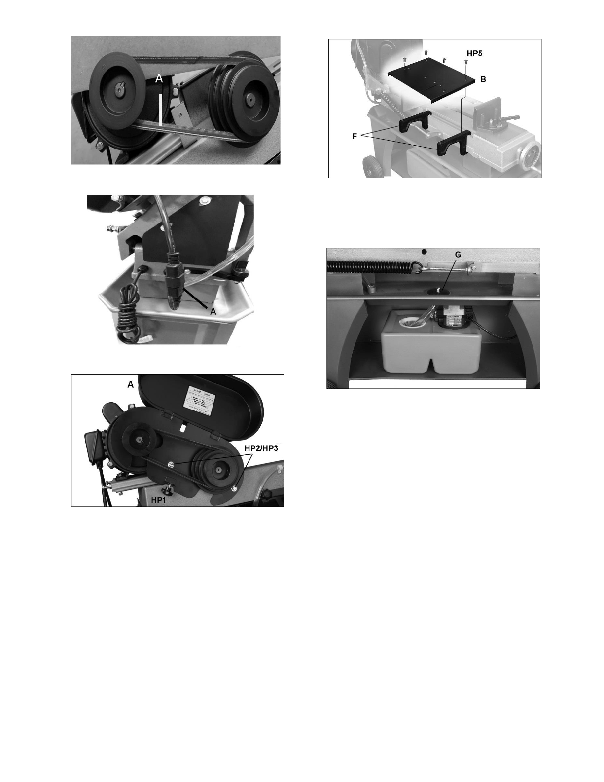
d) Tighten the 5/16" hex screw and nut (A,
Figure 6-9).
e) Install the belt (A, Figure 6-10) on the pulley
of the transmission. For speed selection and
belt tensioning, see section 8.3 Blade Speed.
f) Connect the male/female plug and ensure
that it is always tight (A, Figure 6-10-1)
7. Slide the pulley cover (A, Figure 6-11) over the
spindles and secure with screws and washers
(HP2/HP3), using 10mm wrench.
8. Install the lock screw (HP1) to secure the pulley
cover.
A
Figure 6-8: preset motor position
Figure 6-9: tighten 5/16" hex screw
10
Figure 6-11: installing pulley cover
9. The table plate (B, Figure 6-12) may be used as
cutting table in vertical mode (models 712 and
712D), or may be used as infeed table in
horizontal mode (712D only). To use as infeed
table for model 712D, place supports (F) on
channel of saw bed as shown, and install plate
with flat head screws (HP5).
To use plate as cutting table in vertical mode,
refer to sect. 7.2.
Figure 6-12: installing infeed table (712D only)
10. Place the filter assembly (G, Figure 6-13) over
the drain hole and install the hose under the
filter tube.
Figure 6-13: coolant tank
6.5 Coolant tank preparation
Use of a water-soluble coolant will increase cutting
efficiency and prolong blade life. Do not use black
cutting oil as a substitute. Change cutting oil often
and follow manufacturer’s instructions as to its uses
and precautions.
1) Disconnect machine from power source.
Pour coolant into hole through strainer cup. Fill tank
to approximately 80% of capacity.
Make sure coolant hose is properly connected at
each end, and return hose is connected to drain hole
and positioned in strainer cup, as shown in Figure
6-10.
Figure 6-10: installing belt
Figure 6-10: installing belt
Figure 6-10-1: plug connection
11
7.0 Electrical connections
The HVBS-712 and HVBS-712D Band Saw is rated
at 115/230V power and is pre-wired for 115 volts.
The band saw comes with a plug designed for use
on a circuit with a grounded outlet that looks like the
one pictured in A, Figure 7-1.
The motor cable is designed as a male/female plug,
as a convenience for users when installing the motor
(Figure 7-4).
Before connecting to the power source, be sure the
switch is in the off position.
It is recommended that the band saw be connected
to a dedicated 15 amp circuit with circuit breaker or
fuse. If connected to a circuit protected by fuses, use
time delay fuse marked “D”. Local codes take
precedence over recommendations.
7.1 Grounding instructions
This machine must be grounded. In the event of a
malfunction or breakdown, grounding provides a
path of least resistance for electric current to reduce
the risk of electric shock. This tool is equipped with
an electric cord having an equipment-grounding
conductor and a grounding plug. The plug must be
plugged into a matching outlet that is properly
installed and grounded in accordance with all local
codes and ordinances.
Do not modify the plug provided - if it will not fit the
outlet, have the proper outlet installed by a qualified
electrician.
Improper connection of the equipment-grounding
conductor can result in a risk of electric shock. The
conductor with insulation having an outer surface
that is green with or without yellow stripes is the
equipment-grounding conductor. If repair or
replacement of the electric cord or plug is
necessary, do not connect the equipment-grounding
conductor to a live terminal.
Check with a qualified
electrician or service personnel if the grounding
instructions are not completely understood, or if
in doubt as to whether the tool is properly
grounded. Failure to comply may cause serious
or fatal injury.
Use only 3-wire extension cords that have 3-prong
grounding plugs and 3-pole receptacles that accept
the tool's plug. Position extension cords as to avoid
a trip hazard. Comply with OSHA guidelines.
Repair or replace damaged or worn cord
immediately.
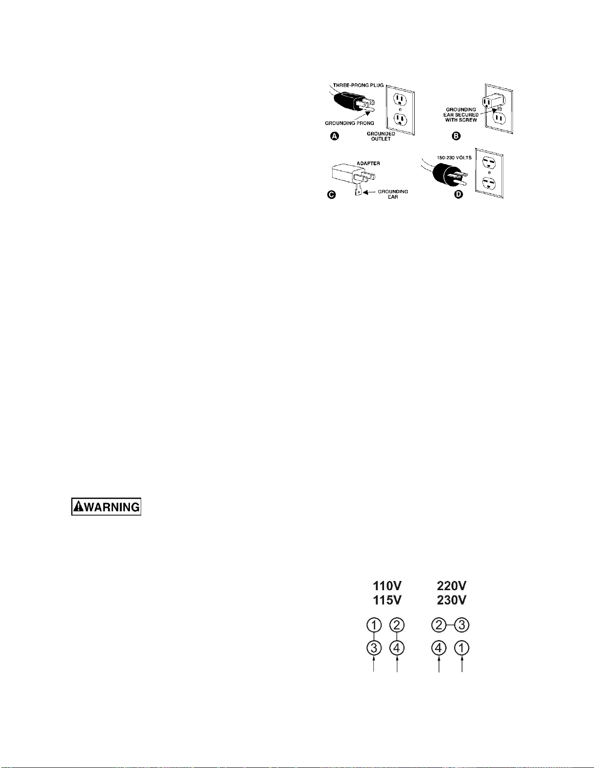
When operated at 115-volt, this tool is intended for
use on a circuit that has an outlet that looks like the
one illustrated in A, Figure 7-1. An adapter, shown
in B and C is not recommended. Provide a properly
grounded outlet (A) installed by a qualified
electrician. Note: In Canada, the use of a temporary
adaptor is not permitted by the Canadian Electrical
Code, C22.1.
Figure 7-1: grounding
When operated at 230-volt, this tool is intended for
use on a circuit that has an outlet that looks like the
one illustrated in D, Figure 7-1. The tool has a
grounding plug that looks like the plug illustrated in
D. Make sure the tool is connected to an outlet
having the same configuration as the plug. No
adapter is available or should be used with this tool.
If the tool must be reconnected for use on a different
type of electric circuit, the reconnection should be
made by qualified service personnel; and after
reconnection, the tool should comply with all local
codes and ordinances.
7.2 Voltage conversion
Conversion from 115V to 230V must be done by
a qualified electrician.
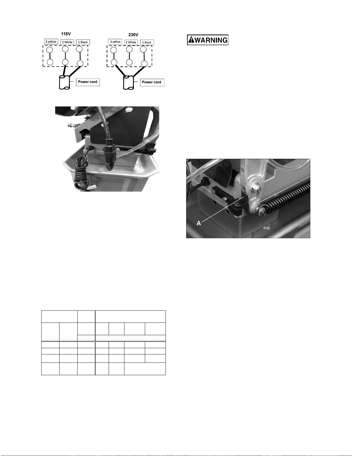
The Band Saw is prewired for 115 volts. To change
incoming leads for 230 volts operation:
1) Open main motor junction box cover, and
change leads based on wiring diagram inside
cover. This diagram is also shown in Figure 7-
2. (NOTE: In case of discrepancy, diagram
inside junction box cover takes precedence.).
Reinstall cover.
2) Remove pump motor junction box cover, and
change incoming leads for coolant pump, based
on diagram shown in Figure 7-3. Reinstall
cover.
3) The plug on the end of the power cord must be
replaced with a UL/CSA listed plug rated for 230
volts operation.
Figure 7-2: main motor wiring
12
7.3 Extension cords
The use of extension cords is discouraged; try to
position machines near the power source. If an
extension cord is necessary, make sure it is in good
condition. When using an extension cord, be sure to
use one heavy enough to carry the current your
product will draw. An undersized cord will cause a
drop in line voltage resulting in loss of power and
overheating.
Table 1 shows correct size to use depending on
cord length and nameplate ampere rating. If in
doubt, use the next heavier gauge. The smaller the
gauge number, the heavier the cord.
Ampere
Rating
Volts
Total length of
cord in feet
More
Than
Not
More
Than
120
240
25
50
50
100
100
200
150
300
AWG
00
06
18
16
16
14
06
10
18
16
14
12
10
12
16
16
14
12
12
16
14
12
Not
Recommended
Table 1: Extension cord recommendations
8.0 Adjustments
Always disconnect band saw
from power source before making adjustments,
unless indicated otherwise.
8.1 Tools required for adjustments
(all may not be needed depending on adjustment)
#2 cross point screwdriver
Wrenches, 10/12/14mm
Hex keys, 3/4/6mm
Square
Straight edge
Clamp
8.2 Vertical bow position
1) Disconnect band saw from power source.
2) Rotate stop bracket (A, Figure 8-1) and hold it
out of the way, while lifting bow to upright
position. Pinch point – use caution!
Figure 8-1: disengaging stop bracket
Steps 3 through 6 are for Model 712D ONLY. For
Model 712, proceed to step 7.
3) The blade guide brackets can be rotated to
facilitate a more comfortable operating position
while in vertical mode. Remove screw (B,
Figure 8-2) with 6mm hex key and position
bracket in adjacent channel. Re-install screw.
4) Repeat above step for top blade guide bracket.
NOTE: Loosen set screw (C, Figure 8-3) and
slide coolant valve assembly out of slot to
access screw (B). When adjustment is
complete, reinstall coolant valve assembly and
tighten set screw (C).
5) Verify that blade guide bearings are set
correctly in relation to blade (see sect. 8.6).
Figure 7-3: coolant pump wiring
Figure 7-4: motor cable w/ plug connected
13
Figure 8-2: lower blade guide rotation (712D only)
Figure 8-3: upper blade guide rotation (712D only)
6) Place smaller support (F, Figure 8-4) onto
groove of blade guide, and adjust height of
blade guide until support sits level on bow
frame, as shown (712D only).
7) Remove deflector plate (D).
8) Install table plate (B) and secure with four
screws (for 712D) or two screws (for 712).
Figure 8-4: installing cutting plate
9) Place a square on table plate and against
blade. Make any needed adjustments until table
plate is square with blade.
8.3 Blade Speed
1) Disconnect band saw from power source.
Place bow in horizontal position.
Open pulley cover, and loosen hex nuts (K, Figure
8-5). Turn screw (L) out to relieve pressure on motor
mount plate.
Turn screws (M) clockwise to push motor mount
plate, relieving tension on belt.
Move belt to desired pulley combination. Refer to
chart inside pulley cover (reproduced in Figure 8-6).
Figure 8-5: blade speed adjustment
Tension belt by backing off screws (M) with 12mm
wrench. Slide motor back into position. Finger
pressure on belt between the pulleys should cause
approximately 1/2-inch deflection. Do not
overtighten belt.
Tighten hex nuts (K) and turn screw (L) to tighten
motor mount plate.
Close pulley cover.
General rule for band saw blade speed: The harder
the material being cut, the slower the blade speed.
Refer to a machinist’s handbook for recommended
speeds.
Figure 8-6
8.4 Blade guides
1) Disconnect the band saw from the power
source.
2) Loosen the knob (N, Figure 7-7) and slide the
blade guide assembly (O) as close as possible
without interference to the material being cut.
Tighten knob.
Figure 8-7: blade guide adjustment
14
8.5 Blade replacement
A general-use variable-tooth blade is provided with
this band saw.
Choice of blade pitch is governed by thickness of
workpiece: the thinner the workpiece, the more
teeth advised. A minimum of 3 teeth should engage
workpiece at all times. If blade teeth are so far apart
that they straddle the work, severe damage to
workpiece and blade can result.
1) Disconnect the machine from the power source.
2) Raise the bow to the vertical position.
Open the rear guard by removing the two (2) knobs
(see Figure 8-10).
Remove the red guard from the upper blade guide
by removing two (2) screws.
It is essential that red blade
guard be installed after new blade has been
fitted. Failure to comply may cause serious
injury.
Release tension on the blade by turning the tension
handle (P, Figure 8-7) counterclockwise. Remove
blade. (Use gloves when handling sharp blades).
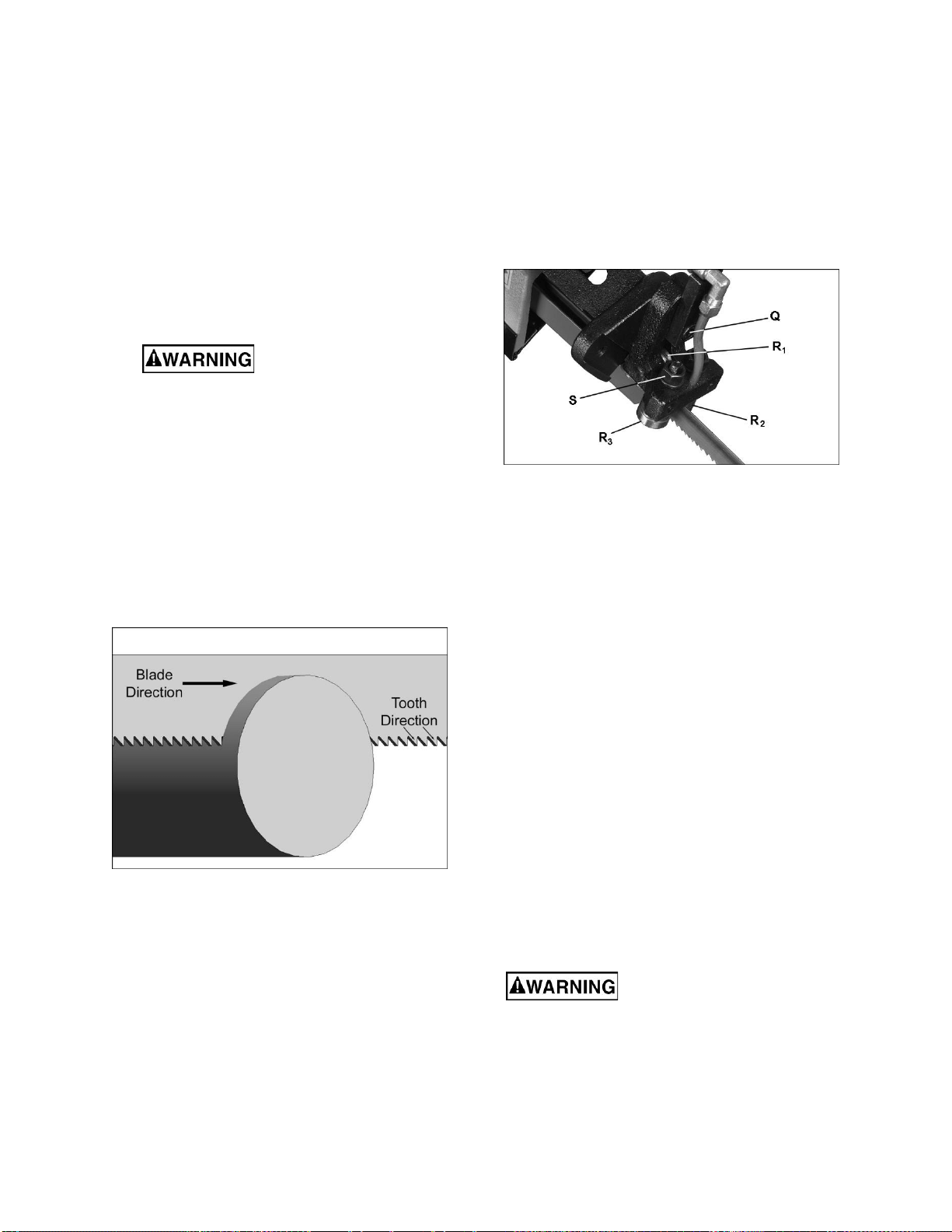
Install the new blade between the blade guide
assemblies and around each wheel. Make sure
blade teeth are pointing in the proper direction. See
Figure 8-8.
Increase blade tension just enough to hold the blade
on the wheels. Make sure the back of the blade rests
lightly against the shoulder of both wheels. Twist the
blade slightly to allow it to slip into the guides.
Figure 8-8
Install red blade guard with screws.
Tension blade fully (see sect. 8.8 Blade tension.)
Place two to three drops of lightweight oil on blade.
Adjust blade guide bearings (see sect. 8.6 Blade
guide bearings).
Connect machine to power source.
Run saw and make sure blade is tracking properly
(sect 8.9. Blade tracking.)
Follow blade break-in procedures (sect. 9.1).
8.6 Blade guide bearings
1) Disconnect the machine from the power source.
2) Loosen the bolt (Q, Figure 8-9) and adjust the
assembly so that the rear bearing (R
1
) is
approximately 0.002 to 0.003 inches from the
back of the blade. Also, the inside bearing (R2)
should very lightly contact the blade. Tighten
bolt (Q).
Inside bearing (R
2
) is fixed. Outside bearing (R
3
)
rotates on an eccentric shaft. Rotate the nut (S) with
a 14mm wrench to adjust the eccentric bearing to a
clearance of 0.001 inches from the blade.
Repeat above steps for the opposite blade guide
assembly.
Figure 8-9: blade guide setting
8.7 Chip brush
The wire chip brush must be properly adjusted and
maintained in working condition, otherwise damage
to the blade can occur. Adjust brush so that its
bristles overlap the blade.
Replace brush if it becomes worn or damaged.
8.8 Blade tension
1) Disconnect the machine from the power source.
Open the rear guard by removing the two (2) knobs
(see Figure 8-10). Observe the position of the blade
on the wheel. If blade is not adjacent to wheel
flange, first adjust the blade tracking according to
sect. 8.9 Blade tracking.
If blade is properly adjacent to wheel flange, slide
blade guide assemblies as far apart as possible, and
tighten in position with knobs (N, Figure 8-7).
Push on the blade to test tension. Finger pressure
should cause approximately 0.004" deflection. Turn
the blade tension handle (P, Figure 8-7) until proper
tension is achieved. For more precise measurement
use a blade tension gauge (not provided).
Return blade guides to operating position.
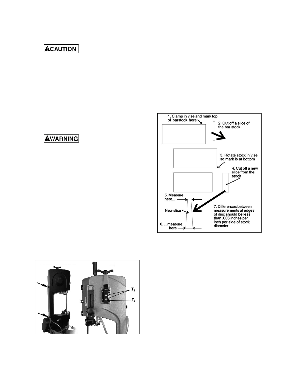
8.9 Blade tracking
Blade tracking adjustment
requires running saw with rear guard open. This
adjustment must be completed by qualified
persons only. Failure to comply may cause
serious injury.
Blade tracking has been set by the manufacturer
and should not need immediate adjustment. If blade
tracking should ever require adjustment:
15
1) Confirm that blade tension is properly set.
Set saw to slowest speed.
Raise bow to vertical position.
Open blade cover.
While performing the
following steps, keep blade from rubbing
excessively on wheel shoulder. Excessive
rubbing will damage wheel and/or blade.
Run saw and observe blade. Blade should run next
to but not tightly against wheel shoulder.
If blade is not tracking properly, loosen bolts (T
1
,
Figure 8-10) with 12mm wrench.
Turn set screw (T
2
) with 4mm hex key, while
observing blade tracking on wheel. Turn set screw
clockwise to track closer to wheel shoulder. Turn set
screw counterclockwise to track away from wheel
shoulder. NOTE: This adjustment is sensitive; start
with 1/4-turns on set screw and allow blade to
respond to changes.
Keep fingers clear of blade
and wheel to avoid injury.
Test the setting by placing a six-inch length of paper
between blade and wheel. The paper should not be
cut as it passes between wheel shoulder and blade.
Turn set screw (T
2
) a small amount. Repeat
insertion of paper between the shoulder and the
blade until paper is cut into two pieces.
NOTE: You may have to repeat the check with
the paper several times before blade and
shoulder cut the paper into two pieces. Do not
hurry the adjustment. Patience and accuracy
here will pay off with better, more accurate,
quieter cutting and longer machine and blade
life.
When paper is cut, back off set screw slightly. This
assures that blade is not touching wheel shoulder.
IMPORTANT: If blade is allowed to run against
wheel shoulder, it will wear off the shoulder.
Once tracking is set, tighten bolts (T
1
).
Figure 8-10: blade tracking adjustment
8.10 Test cut to verify adjustment
Test cuts can be used to determine whether or not
you have adjusted the blade accurately. Use 2-inch
round bar stock to perform these test cuts, as
follows:
1) With bar stock securely clamped in vise, make
a cut through the bar stock. (See Figure 8-11.)
Mark the top of bar stock.
Move the bar stock about 1/4-inch past the blade so
that you can begin a second cut.
Rotate the bar stock 180 degrees so mark you made
is now at bottom of cut.
Make a cut through the bar stock.
Use a micrometer to measure the thickness
variation of the disk you have cut from the bar stock.
Measure at top and bottom of disk.
Figure 8-11
The saw blade can be considered correctly adjusted
when the variation measure is no more than 0.012
inch across the face of the disk.
If you do not have a piece of 2-inch bar stock
available for a test cut, use a larger diameter test
piece rather than a smaller one. The maximum
thickness variation on any test piece should be no
more than 0.003 inch, per side, per inch of stock
diameter.
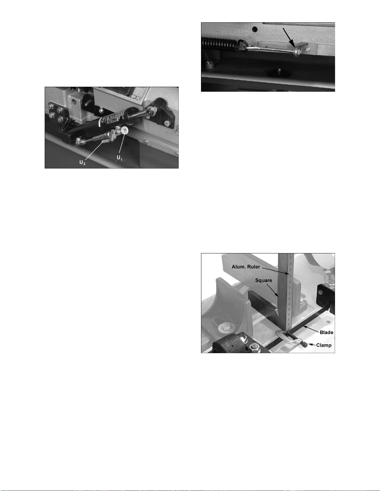
8.11 Setting feed rate
Feed rate of blade into workpiece is important to
band saw performance. Excessive pressure of the
blade against the workpiece may cause stalling or
blade breakage. In contrast, insufficient pressure
rapidly dulls the blade.
The hydraulic cylinder resists bow movement in
downward direction. It offers no resistance when
bow is raised.
16
To increase feed rate, turn dial (U
1
, Figure 8-12)
counterclockwise. To decrease, turn clockwise.
To close hydraulic flow, turn lever (U
2
) down,
perpendicular to cylinder. To open hydraulic flow,
turn lever (U
2
) parallel to cylinder, as shown.
Feed rate is adjusted by operator until saw is
operating efficiently, usually determined by
observing chip formation. See section 9.3,
Evaluating cutting efficiency.
Figure 8-12: feed rate adjustment
8.12 Counterbalance spring
The counterbalance spring helps control the amount
of weight, or feed pressure, the bow puts on the
workpiece when the hydraulic control valve is fully
open. The hydraulic cylinder will not compensate for
improper counterbalance. If the spring is improperly
set, one can expect poor performance, crooked
cuts, tooth stripping, stalling, and/or blade running
off wheels.
The spring tension has been set by the
manufacturer and should not require adjustment. If
future problems arise, indicating improper
counterbalance, adjust spring as follows:
1) Disconnect the machine from the power source.
Open hydraulic cylinder valve and place bow in
horizontal position. Turn hydraulic cylinder dial
counterclockwise until it stops.
Place a weigh scale (such as spring or hanging
scale) beneath the blade tension handle and lift the
saw bow. Scale should indicate approximately 5 to
6 kg (11-13 lb).
If adjustment is needed, loosen one nut and tighten
the other (Figure 8-13) on the eye bolt, until scale
indicates 5 to 6 kg (11-13 lb).
A good indication of proper feed pressure is the
color and shape of the cutting chips. If the chips are
thin or powdered, increase feed pressure. If the
chips are burned and heavy, decrease feed
pressure. If they are still burned and heavy, reduce
blade speed. Optimum feed pressure has been set
when the chips are curled, silvery, and warm.
Figure 8-13: feed pressure adjustment
8.13 Blade-to-table squareness
The blade must be perpendicular to table to ensure
a straight cut. This setting should be confirmed by
the user. Special blade setting gauges can be
purchased for this type of inspection; however, it can
also be done using more common shop items, as
follows.
1) “Extend” the blade surface by clamping a
straight, flat object to blade. (Figure 8-14 uses
small, lightweight aluminum ruler.) Use
lightweight clamp.
Place square on table and against ruler. The square
should lie flat against ruler without a gap.
If there is a gap, loosen bolt (Q, Figure 8-9) on each
blade guide assembly and rotate blade guide
assembly until gap is eliminated between square
and ruler.
Retighten bolts (Q, Figure 8-9).
After making this adjustment, be sure to reinspect
other blade adjustments as noted in this manual.
Figure 8-14: table/blade squareness
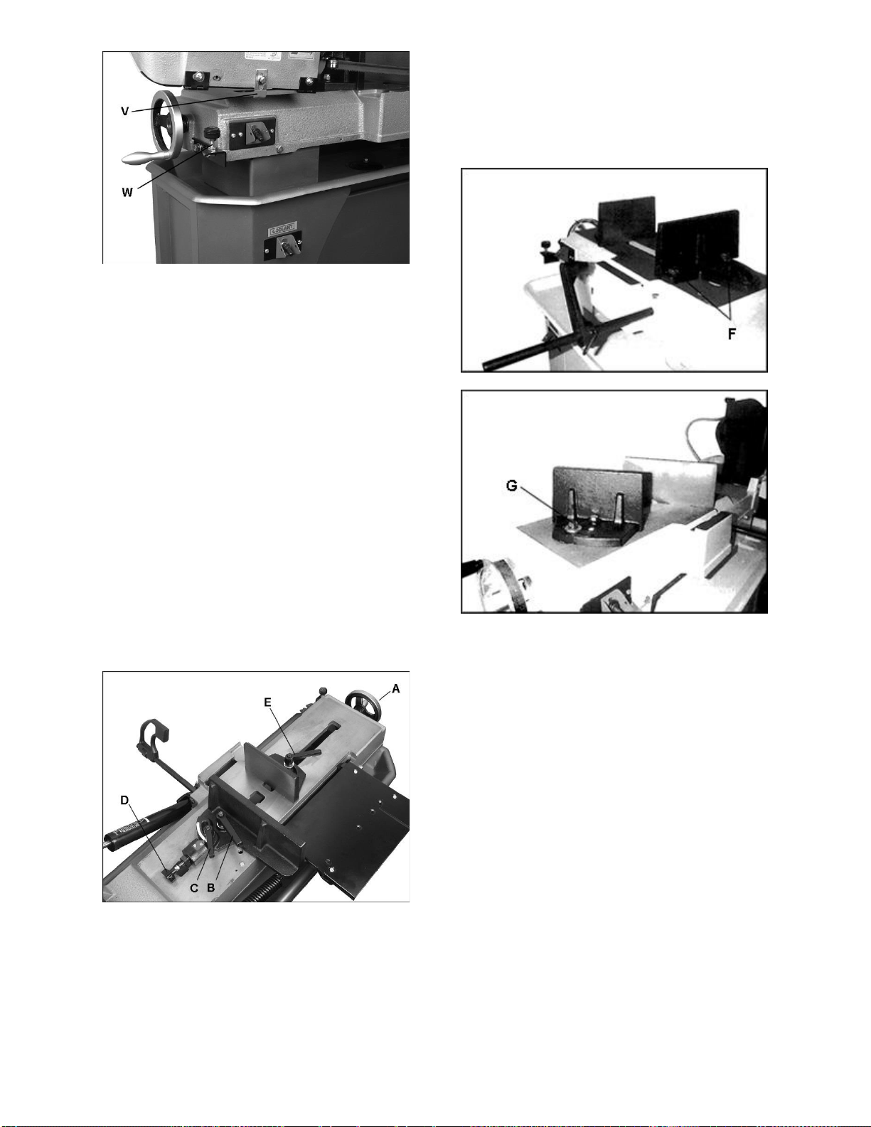
8.14 Auto shut-off adjustment
The saw is properly adjusted when blade shuts off
just after cut completion. To set this:
• If saw completes cut but blade continues
moving, adjust trip tab (V, Figure 8-15)
downward.
• If blade stops before cut is complete, adjust trip
tab (V) upward.
• If blade stops descending and continues
running without completing the cut, turn stop
bolt (W) down.
17
Figure 8-15: shut-off adjustment
8.15 Vise positioning (712D only)
Use handwheel (A, Figure 8-16) to move floating jaw
to open and close vise.
To move complete right jaw assembly, loosen
handle (B).
Vise can be adjusted for square and miter cuts.
Loosen handle (C), pull out stop pin (D), and rotate
fence to desired angle on scale. For standard angles
(0/15/30/45 deg.), allow stop to reengage at detent,
otherwise rotate stop to keep it disengaged.
NOTE: Scale is for reference only; check angles
with protractor if greater precision is needed. (Model
712 scale is located at rear of bed.)
Slightly loosen handle (D) on floating jaw to allow it
to conform to tapered or irregularly-shaped pieces.
Then tighten handle before operating.
TIP: Always verify 90-degree vise position by using
a square against the blade and vise.
The vise handles are adjustable. Pull up on handle
and rotate it on pin, then allow it to drop back onto
pin. Make sure vise handles are positioned to
prevent contact with descending bow.
Figure 8-16: vise positioning (712D only)
8.16 Vise positioning (712 only)
To set vise for 90 to 45 degree cutting:
1) Remove bolt and nut assemblies (F, Figure 8-
17).
2) Position vise and reinstall as shown in Figure 8-
17. Pay particular attention to bolt hole location.
3) Set vise to desired angle, reinstall nuts and
bolts, and tighten nut and bolt assemblies.
4) Adjust floating vise parallel to fixed vise by
loosening bolt (G, Figure 8-18), adjusting to
parallel, and tightening bolt.
Figure 8-17: vise positioning (712 only)
Figure 8-18: vise positioning (712 only)
To set vise for maximum width of stock cutting:
1) Remove nut and bolt assemblies.
Position vise and reinstall bolt assemblies as shown
in Figure 8-17.
9.0 Operation
9.1 Blade break-in
New blades are very sharp and, therefore, have a
tooth geometry which is easily damaged if a careful
break-in procedure is not followed. Consult the
blade manufacturer’s literature for break-in of
specific blades on specific materials. However, the
following procedure will be adequate for break-in of
JET-supplied blades on lower alloy ferrous
materials.
2) Clamp a round section workpiece in the vise.
The workpiece should be 2 inches or larger in
diameter.
Set the saw on low speed. Start the cut with a very
light feed rate.

18
When the saw has completed 1/3 of the cut,
increase feed rate slightly and allow saw to
complete the cut.
Keep the same hydraulic cylinder setting and begin
a second cut on the same or similar workpiece.
When blade has completed about 1/3 of cut,
increase feed rate. Watch chip formation until
cutting is at its most efficient rate and allow saw to
complete the cut (see sect. 9.3, Evaluating cutting
efficiency).
The blade is now ready for regular service.
9.2 General operating procedure
IMPORTANT: When cutting magnesium, never use
soluble oils or emulsions (oil-water mix) as water will
greatly intensify any accidental magnesium chip fire.
See your industrial coolant supplier for specific
coolant recommendations when cutting
magnesium.
1) Give machine an overall inspection. Verify that
all guards, covers, etc. are in place and in
working order, the blade is tensioned properly,
and tooth direction matches arrow on bow.
Check that blade guides and wire brush are set
correctly.
2) Raise bow until it will clear workpiece by a few
inches, and secure in position by closing
cylinder valve.
Always secure bow in
raised position before loading material.
Never start a cut with blade contacting
workpiece.
3) Position workpiece in vise and tighten vise.
Workpiece should be fitted directly between the
jaws without adding other objects. When work
piece is profiled section, flat piece or special
shape, refer to examples in Figure 9-1 for
proper clamping positions. The top row shows
acceptable clamping positions, the bottom row
show unacceptable positions.
If the thickness of profile section is very thin, a
piece which duplicates the profile should be
fitted inside the workpiece itself, to prevent
workpiece being crushed between the jaws.
Do not load/unload material
from vise while machine is running. Never hold
workpiece by hand when cutting; workpiece
must be firmly secured in vise. Do not reach into
cutting area during cutting operations.
Figure 9-1: clamping positions
4) Adjust left blade guide to minimize exposed
blade area.
5) Set suitable feed rate on cylinder dial.
6) Open coolant valve, and open valve on
hydraulic cylinder to allow bow to descend in
gradual and controlled manner.
7) Switch trip tab must turn off saw at completion
of cut.
9.3 Evaluating cutting efficiency
Is the blade cutting efficiently? The best way to
determine this is to observe the chips formed by the
cutting blade.
If chip formation is powdery, then the feed rate is
much too light, or the blade is dull.
If chips formed are curled, but colored — that is,
either blue or straw-colored from heat generated
during the cut — then the feed rate is too high.
If chips are slightly curled and are not colored by
heat – the blade is sufficiently sharp and is cutting
at its most efficient rate.
10.0 User-maintenance
Always disconnect power to
machine before performing maintenance.
Failure to do this may result in serious personal
injury.
Keep all surfaces clean and free of rust, slag, chips,
and coolant build-up.
Clear metal particles with a small paint brush or
parts cleaning brush. Do not use compressed air, as
it may force chips into the guide bearings and other
critical areas of the saw.
Clean drain filter assembly.
Make frequent inspections of motor fan, and blow
out (with low pressure air hose) or vacuum any
accumulation of foreign material to maintain normal
motor ventilation.
Wipe saw down with a clean, dry cloth, and oil all
unpainted surfaces with light machine oil.
Keep blade guides clean and free of metal particles.
Check guide bearings frequently to make sure that
they are properly adjusted and turning freely.
Periodically inspect belt for wear or fraying. Replace
if needed.

19
To prevent corrosion of machined surfaces when a
soluble oil is used as coolant, pay particular
attention to wiping dry the surfaces where fluid
accumulates and does not evaporate quickly, such
as between machine bed and vise.
Place a thin coat of oil on bed surface on which vise
jaw slides.
If the power cord is worn, cut, or damaged in any
way, have it replaced immediately.
10.1 Lubrication
All ball bearings are permanently lubricated and
sealed. They require no further lubrication.
Lubricate the vise lead screw as needed with #2
tube grease.
Drain and refill gear box oil after first 90 days of
operation. Thereafter, change every six months.
Use 90W oil.
To change gear box oil:
1) Disconnect machine from power source.
Place bow in horizontal position.
Remove four screws from gear box and remove
cover plate and gasket. If more space is needed to
access gearbox, remove belt and adjust motor
away.
Hold a container under lower right corner of gear
box with one hand while slowly raising bow with the
other. Drain completely.
Return bow to horizontal position. Wipe out
remaining oil with a rag.
Replace gasket and cover. Fasten cover with
screws.
Remove vent plug (Figure 10-1) with 8mm wrench
and fill gear box with approximately 1/2 pint of 90W
oil, through the hole. Reinstall vent plug.
Figure 10-1: gearbox
10.2 Coolant level
Maintain coolant level. Low coolant level can cause
foaming and high blade temperatures. Replace dirty
coolant; dirty or weak coolant can clog the pump,
cause crooked cuts, a low cutting rate and/or
permanent blade damage. To fill tank, pour coolant
into hole through strainer cup to about 80% of full
capacity. Full capacity is 9 liters (2.5 gal). Follow
coolant manufacturer’s instructions for proper use
and disposal.
10.3 Additional servicing
Any additional servicing on the band saw should be
performed by an authorized service representative.

20
11.0 Troubleshooting HVBS-712/712D Band Saw
11.1 Mechanical and electrical problems
Symptom
Possible Cause
Correction *
Motor will not start.
No incoming power.
Check plug connection. If satisfactory, check
breaker or fuse.
Low voltage.
Check power line for proper voltage.
Open circuit in motor or loose
connection.
Inspect all lead connections on motor for
loose or open connections.
Motor will not start, or
motor stalls, resulting
in blown fuse or tripped
breaker.
Too many tools running on one
circuit.
Reduce number of tools connected to circuit.
Short circuit in line cord or plug.
Inspect cord or plug for damaged insulation
and shorted wires.
Short circuit in motor or loose
connections.
Inspect all connections on motor for loose or
shorted terminals or worn insulation.
Incorrect fuses or circuit breakers in
power line.
Install correct fuses or circuit breakers.
Motor overheats.
Motor overloaded.
Reduce load on motor: increase speed or
decrease feed pressure.
Air circulation through motor is
restricted.
Clean motor fan with compressed air to
restore normal air circulation.
Machine slows when
operating.
Excessive feed pressure.
Adjust spring tension to reduce feed
pressure or increase speed using belt
adjustment.
Belt loose.
Tighten belt.
Loud, repetitive noise
coming from machine.
Pulley setscrews are missing or
loose.
Inspect setscrews. Replace or tighten if
necessary.
Motor fan is hitting the cover.
Tighten fan or shim cover.
V-belt is defective.
Replace V-belt.
Excessive vibrations.
Base on uneven surface.
Move to level surface.
Saw blade has cracks.
Replace blade immediately.
Too heavy a cut.
Reduce feed rate and blade speed.
No coolant flow.
Coolant level low.
Add coolant to tank.
Filter screen clogged.
Clean filter screen.
Pump motor faulty.
Replace pump.
* WARNING: Some corrections may require a qualified electrician.

21
11.2 Operational problems
Symptom
Possible Cause
Correction
Cuts not square.
Blade not square to vise/material.
Adjust vise square to blade.
Blade surface not perpendicular to
table.
Adjust blade guides until perpendicular.
Workpiece shifting in vise.
Properly secure workpiece by tightening
vise handles. If irregular-shaped workpiece,
use appropriate clamping technique or jig.
Low blade tension.
Increase tension.
Blade guides out of adjustment.
Adjust blade guides.
Blade is worn, cutting crooked.
Replace blade.
Feed pressure too great.
Reduce feed pressure.
Blade guides incorrectly set.
Readjust guide assemblies.
Incorrect blade toothing in relation to
workpiece.
Check Machinery’s Handbook for
recommended blade type.
Miter cuts not accurate.
Improper setting of vise jaws.
Use adjustable square or protractor to
verify angle settings.
Blade worn; cutting crooked.
Replace blade.
Premature dulling of
blade teeth
Improper blade break-in.
Follow proper break-in procedure.
Excessive blade speed, blade teeth
overheating.
Decrease speed.
Inadequate feed rate.
Adjust cylinder dial setting as needed.
Improper tooth pitch for material.
Use proper blade.
Hard spots or scale on material.
Scale: reduce speed and increase feed
rate. Hard Spots: increase feed rate.
Work hardening of material (especially
stainless steel).
Increase feed rate.
Blade installed backwards.
Remove blade and twist inside-out.
Insufficient blade tension.
Adjust as needed.
Finished surface of
workpiece is rough,
unsatisfactory.
Improper blade break-in.
Follow proper break-in procedure.
Improper speed or feed rate.
Adjust as needed.
Dull or damaged teeth.
Replace blade.
Poor weld on blade.
Replace or re-weld blade.
Incorrect choice of blade.
Check a machinist’s handbook for blade
recommendations.
Excessive blade
breakage.
Incorrect blade tension.
Adjust accordingly.
Incorrect blade speed or downfeed
rate.
Adjust accordingly.
Workpiece loose in vise.
Clamp workpiece securely.
Blade rubs on wheel shoulder.
Adjust blade tracking.
Teeth too coarse for material.
Use appropriate blade for material.
Teeth in contact with workpiece
before saw is started.
Blade must be running before contact with
workpiece.
Blade guides misaligned.
Adjust blade guides.
Blade too thick for wheel diameter.
Use thinner blade.
Cracking at weld; poor annealing of
blade.
Replace blade.

22
12.0 Replacement Parts
Replacement parts are listed on the following pages. To order parts or reach our service department, call 1-800-
274-6848 Monday through Friday, 8:00 a.m. to 5:00 p.m. CST. Having the Model Number and Serial Number of
your machine available when you call will allow us to serve you quickly and accurately.
Some parts are shown for reference only and may not be available individually. Non-proprietary parts, such as
fasteners, can usually be found at local hardware stores, or may be ordered from JET.
23
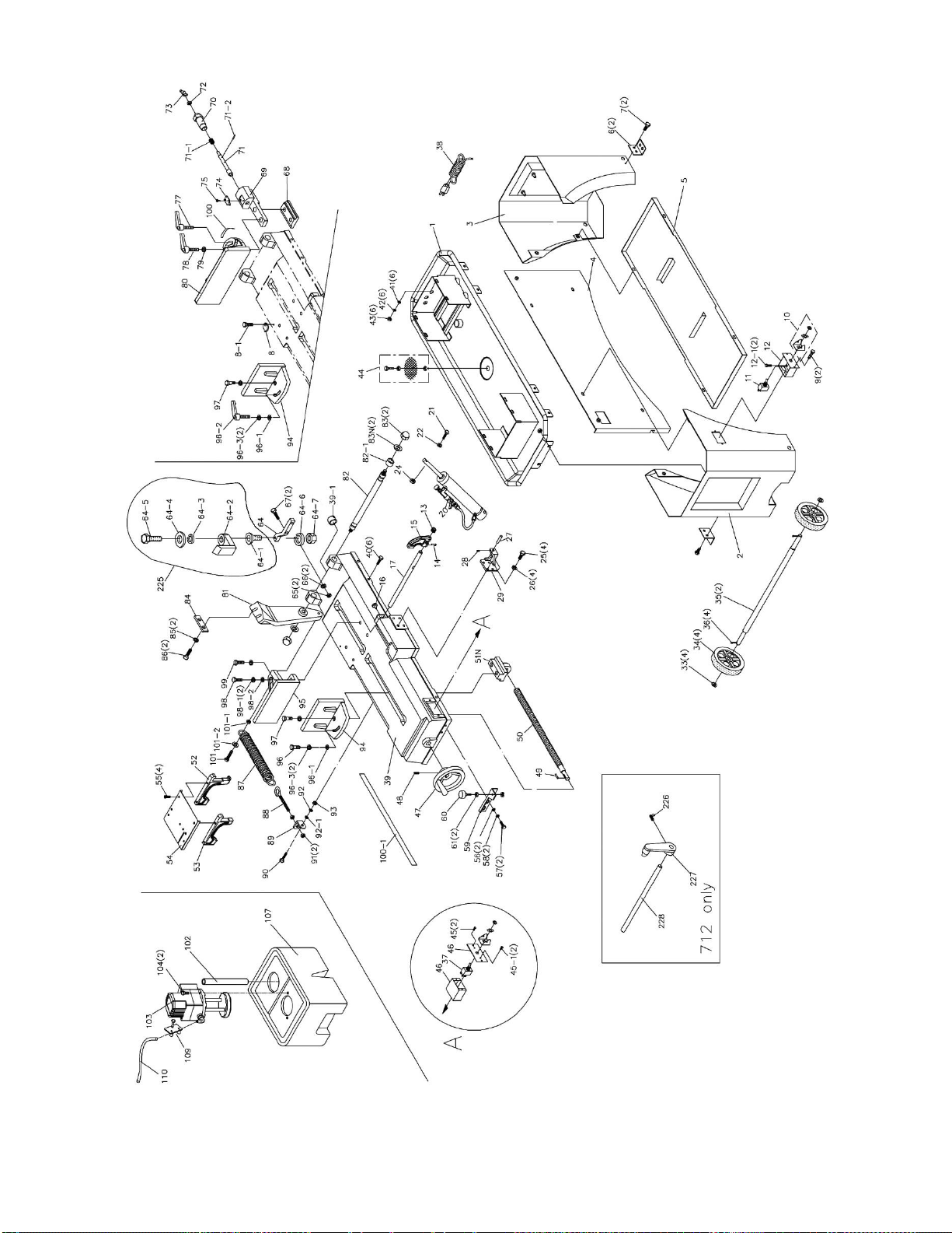
12.1.1 HVBS-712/712D Bed and Stand Assembly – Exploded View
24
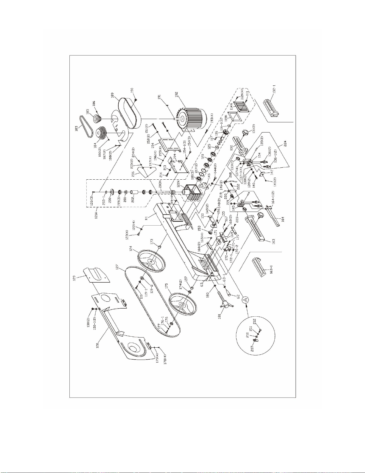
12.1.2 HVBS-712/712D Bow Assembly – Exploded View

25
12.1.3 HVBS-712/712D – Parts List
Index No Part No Description Size Qty
.................. HVBS712-SA ............ Stand Assembly (includes #1 thru 5) ....................... ...................................... 1
1 ................ HVBS712-01 ............. Water Tray ............................................................... ...................................... 1
2 ................ HVBS712-02 ............. Stand – Left ............................................................. ...................................... 1
3 ................ HVBS712-03 ............. Stand – Right ........................................................... ...................................... 1
4 ................ HVBS712-04 ............. Front Plate ............................................................... ...................................... 1
5 ................ HVBS712-05 ............. Pump Support Plate ................................................ ...................................... 1
6 ................ HVBS712-06 ............. Shipping Brace ........................................................ ...................................... 2
7 ................ TS-0051011 .............. Hex Cap Screw ........................................................ 5/16” x 1/2" .................... 2
8 ................ HVBS712-08 ............. 90-Degree Plate ...................................................... ...................................... 1
8-1 ............. TS-081F032 .............. Phillips Pan Head Machine Screw ........................... 1/4" x 1/2"...................... 1
9 ................ 6293226 .................... Phillips Pan Head Machine Screw ........................... 3/16” x 3/8" .................... 2
10 .............. HVBS712-10 ............. Switch Guard Kit ...................................................... ...................................... 1
11 .............. HVBS712-11 ............. Toggle Switch .......................................................... ...................................... 1
.................. HVBS712-11A ........... Toggle Switch with Guard Assembly (includes #10,11).................................. 1
12 .............. HVBS712-12 ............. Electrical Box ........................................................... ...................................... 1
12-1 ........... 5711571 .................... Phillips Pan Head Machine Screw ........................... 3/16"x1/4"...................... 2
13 .............. HVBS712-13 ............. Threaded Collar (712D only) ................................... ...................................... 1
14 .............. HVBS712-14 ............. Plastic Knob (712D only) ......................................... 1/4" x 1/2"...................... 1
15 .............. HVBS712-15 ............. Work Stop (712D only) ............................................ ...................................... 1
16 .............. HVBS712-16 ............. Knob ........................................................................ 1/4" x 1/2"...................... 1
17 .............. HVBS712-17 ............. Work Stop Rod (712D only) ..................................... ...................................... 1
20 .............. HVBS712-18 ............. Hydraulic Cylinder Assembly ................................... ...................................... 1
21 .............. TS-1505061 .............. Socket Head Cap Screw ......................................... M10x40 ......................... 1
22 .............. TS-1550071 .............. Flat Washer ............................................................. M10 ............................... 1
24 .............. TS-1540071 .............. Hex Nut .................................................................... M10 ............................... 1
25 .............. TS-0060051 .............. Hex Cap Screw ....................................................... 3/8" x 1"......................... 4
26 .............. TS-0720091 .............. Lock Washer ........................................................... 3/8" ................................ 4
27 .............. HVBS712-27 ............. Cylinder Support Shaft............................................. ...................................... 1
28 .............. TS-0267041 .............. Set Screw ................................................................ 1/4" x 3/8"...................... 1
29 .............. HVBS712-29 ............. Lower Cylinder Support ........................................... ...................................... 1
33 .............. TS-0680081 .............. Flat Washer * ........................................................... 5/8" ................................ 4
34 .............. 5518229N .................. Wheel ...................................................................... 8" ................................... 4
35 .............. HVBS712-35 ............. Wheel Shaft ............................................................. ...................................... 2
36 .............. 5518231N .................. Cotter Pin * .............................................................. ...................................... 4
37 .............. HVBS7MW-31AN ...... Toggle Switch with Guard Assembly ....................... ...................................... 1
38 .............. HVBS7MW-26 ........... Power Cord ............................................................. 16AWGx3C .................. 1
.................. HVBS7MW-26-1 ........ Power Cord for Motor (not shown)........................... 16AWGx5C ................... 1
.................. HVBS7MW-26-2 ........ Power Cord for Pump (not shown) .......................... 16AWGx3C ................... 1
.................. HVBS712-38 ............. Front Power Cord with Plug (not shown) ................. 16AWGx3C ................... 1
.................. HVBS712-38-1 .......... End Power Cord (not shown) .................................. 16AWGx3C ................... 1
.................. HVBS712-26-1 .......... Motor Cord with Female plug (not shown) ............... 16AWGx3C ................... 1
.................. HVBS712-26-2 .......... Motor Cord with Male Plug (not shown)................... 16AWGx3C ................... 1
39 .............. HVBS712-39 ............. Bed .......................................................................... ...................................... 1
39-1 ........... HVBS712-39-1 .......... Strain Relief ............................................................. MG16A-10B .................. 2
40 .............. TS-0051051 .............. Hex Cap Screw ........................................................ 5/16 "x 1"....................... 6
41 .............. TS-0680031 .............. Flat Washer ............................................................. 5/16" .............................. 5
42 .............. TS-0720081 .............. Lock Washer ............................................................ 5/16" .............................. 5
43 .............. TS-0561021 .............. Hex Nut .................................................................... 5/16" .............................. 5
44 .............. HVBS7MW-29 ........... Filter Assembly ........................................................ ...................................... 1
45 .............. HVBS7MW-30 ........... Pan Head Cross Screw ........................................... 3/16" x 3/8".................... 2
45-1 ........... 5711571 .................... Phillips Pan Head Machine Screw ........................... 3/16"x1/4"...................... 2
46 .............. HVBS712-46 ............. Main Switch Box ...................................................... 2 hole ............................ 1
.................. HVBS712-46N ........... Main Switch Box ...................................................... 3 hole ............................ 1
.................. HVBS712-46N-1 ....... Strain Relief (not shown) ......................................... SB7R-1 ......................... 3
47 .............. HVBS712-47 ............. Handwheel ............................................................... ...................................... 1
48 .............. TS-0270031 .............. Set Screw ................................................................ 5/16" x 3/8".................... 1

26
Index No Part No Description Size Qty
49 .............. HVBS712-49 ............. Round Key ............................................................... 5x20 .............................. 1
50 .............. HVBS712-50 ............. Lead Screw .............................................................. ...................................... 1
51N ............ HVBS7MW-35 ........... Nut Seat .................................................................. ...................................... 1
52 .............. HVBS712-52 ............. Support B (712D only) ............................................. ...................................... 1
53 .............. HVBS712-53 ............. Support A (712D only) ............................................. ...................................... 1
54 .............. HVBS712-54 ............. Table Plate .............................................................. ...................................... 1
55 .............. F010696 .................... Socket Head Flat Screw * ........................................ 1/4" x 3/8"...................... 4
56 .............. TS-0680031 .............. Flat Washer ............................................................. 5/16" .............................. 2
57 .............. TS-0051031 .............. Hex Cap Screw ........................................................ 5/16" x 5/8".................... 2
58 .............. TS-0720081 .............. Lock Washer ............................................................ 5/16" .............................. 2
59 .............. HVBS7MW-37 ........... Support Plate ........................................................... ...................................... 1
60 .............. HVBS7MW-38 ........... Stop Screw .............................................................. ...................................... 1
61 .............. TS-0561021 .............. Hex Nut .................................................................... 5/16" .............................. 2
62 .............. HVBS712-62 ............. Plastic Knob ............................................................ M12 ............................... 1
63 .............. TS-1540081 .............. Hex Nut ................................................................... M12 ............................... 1
63-1 ........... TS-2360121 .............. Flat Washer ............................................................. M12 ............................... 2
64 .............. HVBS7MW-41 ........... 90 degree Support ................................................... ...................................... 1
64-1 ........... HVBS7MW-151 ......... Support Screw ......................................................... ...................................... 1
64-2 ........... HVBS7MW-152 ......... Bracket .................................................................... ...................................... 1
64-3 ........... HVBS7MW-153 ......... Spring ................................................................... ...................................... 1
64-4 ........... HVBS7MW-154 ......... Spring Cap ............................................................... ...................................... 1
64-5 ........... HVBS7MW-155 ......... Socket Head Cap Screw ......................................... 3/16” x 1/2” .................... 1
64-6 ........... TS-0720091 .............. Lock Washer ........................................................... 3/8" ................................ 1
64-7 ........... TS-0561031 .............. Hex Nut ................................................................... 3/8" ................................ 1
65 .............. TS-0561031 .............. Hex Nut ................................................................... 3/8" ................................ 2
66 .............. TS-0720091 .............. Lock Washer ........................................................... 3/8" ................................ 2
67 .............. TS-0060071 .............. Hex Cap Screw ....................................................... 3/8" x 1-1/2" .................. 2
68 .............. HVBS712-68 ............. T- Block .................................................................. ...................................... 1
69 .............. HVBS712-69 ............. Miter Vise Support Bracket ..................................... ...................................... 1
70 .............. HVBS712-70 ............. Angle Lock Screw .................................................... ...................................... 1
71 .............. HVBS712-71 ............. Locking Pin .............................................................. ...................................... 1
71-1 ........... HVBS712-71-1 .......... Spring ..................................................................... ...................................... 1
71-2 ........... JNS7033-33 .............. Roll Pin ................................................................... Ø3x25L ......................... 1
72 .............. TS-0561011 .............. Hex Nut .................................................................... 1/4” ................................ 1
73 .............. HVBS712-73 ............. Plastic Knob ............................................................. 1/4” ................................ 1
74 .............. HVBS712-74 ............. Indicator ................................................................... ...................................... 1
75 .............. HVBS710S-175 ......... Round Cross Screw ................................................. 3/16" X 1/4" ................... 2
77 .............. HVBS712-77 ............. Quick Handle ........................................................... 1/2" x 1-1/2" .................. 1
78 .............. HVBS712-78 ............. Quick Handle ........................................................... 1/2" x 2-1/2" .................. 1
79 .............. TS-0680061 .............. Flat Washer ............................................................. 1/2" ............................... 1
80 .............. HVBS712-80 ............. Vise Jaw, Right (712D only) .................................... Deluxe model ................ 1
81 .............. HVBS712-81 ............. Pivot Arm ................................................................. ...................................... 1
82 .............. HVBS712-82 ............. Support Shaft ........................................................... Ø22 ............................... 1
82-1 ........... HVBS712-82-1 .......... Spacer ..................................................................... ...................................... 1
83 .............. HVBS712-83 ............. Locking Nut .............................................................. 1/2" ............................... 2
83N ............ TS-0680061 .............. Flat Washer ............................................................. 1/2" ............................... 2
84 .............. HVBS7MW-60 ........... Arm Support Plate ................................................... ...................................... 1
85 .............. TS-0720091 .............. Lock Washer ............................................................ 3/8" ............................... 2
86 .............. TS-0060071 .............. Hex Cap Screw ........................................................ 3/8" x 1-1/2" .................. 2
87 .............. HVBS712-87 ............. Extension Spring ..................................................... ...................................... 1
88 .............. HVBS712-88 ............. Eye Bolt ................................................................... ...................................... 1
89 .............. HVBS712-89 ............. Spring Bracket ........................................................ ...................................... 1
90 .............. TS-0051051 .............. Hex Cap Screw ....................................................... 5/16" x 1"....................... 2
91 .............. TS-0561031 .............. Hex Nut .................................................................... 3/8" ................................ 2
92 .............. TS-0720081 .............. Lock Washer ........................................................... 5/16" .............................. 1
92-1 ........... TS-0680031 .............. Flat Washer ............................................................ 5/16" .............................. 1
93 .............. TS-0561021 .............. Hex Nut ................................................................... 5/16" .............................. 1

27
Index No Part No Description Size Qty
94 .............. HVBS712-94 ............. Vise Jaw – Left (712 & 712D) .................................. Deluxe Model ............... 1
95 .............. HVBS7MW-58 ........... Vise Jaw – Right (712 only) ..................................... Base Model .................. 1
96 .............. TS-0060071 .............. Hex Cap Screw ....................................................... 3/8 x 1-1/2" .................... 1
96-1 ........... TS-0680041 .............. Flat Washer ............................................................ 3/8" ................................ 2
96-2 ........... HVBS712-96-2 .......... Quick Handle .......................................................... 3/8" x 1-1/2" .................. 1
96-3 ........... TS-0720091 .............. Lock Washer ........................................................... 3/8" ................................ 2
97 .............. TS-0060071 .............. Hex Cap Screw (712 only) ....................................... 3/8" x 1-1/2" .................. 1
98 .............. TS-0070031 .............. Hex Cap Screw ....................................................... 1/2" x 1-1/2” .................. 1
98-1 ........... TS-0720111 .............. Lock Washer ........................................................... 1/2" ................................ 2
98-2 ........... TS-0680061 .............. Flat Washer ............................................................ 1/2" ................................ 1
99 .............. TS-0100041 .............. Hex Cap Screw ....................................................... 1/2" x 1-1/4" .................. 1
100 ............ HVBS712-100 ........... Scale (712D only) .................................................... Deluxe Model ................ 1
100-1 ......... HVBS712-100-1 ........ Scale (712 only) ....................................................... Base Model ................... 1
101 ............ TS-0209081 .............. Socket Head Cap Screw ........................................ 3/8" x 1-3/4" .................. 1
101-1 ......... TS-0561031 .............. Nut .......................................................................... 3/8" ................................ 1
101-2 ......... TS-0680041 .............. Flat Washer ............................................................. 3/8” ................................ 1
102 ............ HVBS712-102W ........ Hose ........................................................................ 1" ................................... 1
103 ............ HVBS712-103W ........ Coolant Pump .......................................................... 1/8HP 115/230V .......... 1
104 ............ TS-0050031 .............. Hex Cap Screw ........................................................ 1/4" x 3/4"...................... 4
107 ............ HVBS712-107N ......... Coolant Tank ........................................................... ...................................... 1
109 ............ HVBS7MW-68 ........... Hose Clamp ............................................................. 13mm ............................ 1
110 ............ HVBS712-110W ........ Hose ........................................................................ 5/16" .............................. 1
111 ............ HVBS712-111W ........ Bow .......................................................................... ...................................... 1
112N .......... HVBS712-112N ......... Hex Cross Head Bolt ............................................... 1/4" X1/2" ...................... 4
113 ............ HVBS7MW-71 ........... Vent Plug ................................................................ ...................................... 1
114N .......... HVBS7MW-72G ........ Gear Box Cover ....................................................... ...................................... 1
115N .......... HVBS7MW-73 ........... Gear Box Gasket ..................................................... ...................................... 1
116 ............ HVBS712-116N ......... Worm Gear .............................................................. ...................................... 1
116-1 ......... HBS916W-49 ............ C-Ring ..................................................................... S25 ............................... 1
117 ............ HVBS7MW-142 ......... Key .......................................................................... 6x6x20 .......................... 1
118 ............ BB-6005Z .................. Ball Bearing ............................................................ 6005 .............................. 3
119 ............ F006229 .................... Hex Cap Screw ........................................................ 3/8"-16 x 7/8" ................ 1
119-1 ......... TS-0720091 .............. Lock Washer ............................................................ 3/8" ................................ 1
119-2 ......... HVBS7MW-145 ......... Flat Washer ............................................................. 3/8"x35x4 ...................... 1
120 ............ HVBS7MW-78 ........... Oil Seal .................................................................... 25. 47. 7 ........................ 1
121A .......... HVBS7MW-79GA ...... Gear Box Assembly ................................................. ...................................... 1
121N .......... HVBS7MW-79G ........ Gear Box ................................................................. ...................................... 1
122 ............ TS-0720081 .............. Lock Washer ............................................................ 5/16" .............................. 4
123 ............ TS-0081051 .............. Hex Cap Screw ........................................................ 5/16" x 1-1/4" ................ 4
123-1 ......... TS-0207072 .............. Socket Head Cap Screw ......................................... 1/4" X 1/4" ..................... 2
124 ............ HVBS7MW-80N ........ Blade Drive Wheel ................................................... ...................................... 1
125 ............ HVBS7MW-81 ........... Worm Bushing ......................................................... ...................................... 1
126 ............ TS-0206021 .............. Socket Head Cap Screw ......................................... 3/16” x 3/8” .................... 3
127 ............ 414304 ...................... Bi-Metal Blade ......................................................... 3/4x0.035x93 6/10VT .... 1
128 ............ HVBS712-128W ........ Rear Guard .............................................................. ...................................... 1
129 ............ HVBS7MW-83 ........... Wheel Cover ............................................................ ...................................... 1
130 ............ HVBS7MW-85 ........... Plum Screw ............................................................. ...................................... 2
130-1 ......... TS-0680021 .............. Flat Washer ............................................................. 1/4" ................................ 2
131 ............ HVBS7MW-86 ........... Lock Knob ................................................................ ...................................... 2
132 ............ HVBS712D-132 ......... Adjustable Bracket – Right (712D only) ................... Deluxe Model ............... 1
132-1 ......... HVBS7MW-87 ........... Adjustable Bracket – Right (712 only) ..................... Base Model .................. 2
133 ............ BB-608ZZ .................. Ball Bearing ............................................................ 608ZZ ........................... 2
134 ............ HVBS712-134W ........ Adjustable Blade Seat – Right ................................. ...................................... 1
135 ............ HVBS7MW-90 ........... Bearing Pin ............................................................. ...................................... 2
136 ............ HVBS7MW-91 ........... Eccentric Shaft Assembly (outside) ......................... ...................................... 2
136-1 ......... HVBS7MW-91A ........ Center Shaft Assembly (inside) ............................... ...................................... 2
137 ............ TS-0561031 .............. Hex Nut .................................................................... 3/8" x 24UNF ................ 4

28
Index No Part No Description Size Qty
137-1 ......... TS-0720091 .............. Lock Washer ............................................................ 3/8" ................................ 4
138 ............ TS-0680031 .............. Flat Washer ............................................................. 5/16" .............................. 2
139 ............ TS-0720081 .............. Lock Washer ............................................................ 5/16" .............................. 2
140 ............ HVBS712-140W ........ Hex Socket Cap Screw ............................................ 5/16" x 1-1/8" ................ 1
141 ............ HVBS712-141W ........ Flat Pan Head Screw ............................................... 1/4" X 3/8" ..................... 2
142 ............ HVBS712-142 ........... Deflector Plate ......................................................... ...................................... 1
143 ............ HVBS712-143W ........ Adjustable Blade Seat – Left ................................... ...................................... 1
144 ............ TS-0060031 .............. Hex Cap Screw ........................................................ 3/8" X 3/4" ..................... 2
145 ............ HVBS712-145N ......... Upper Cylinder Support ........................................... ...................................... 1
146 ............ TS-0720091 .............. Lock Washer ............................................................ 3/8" ................................ 2
148 ............ TS-0813032 .............. Round Head Screw ................................................. 1/4” x 1/2” ..................... 2
149 ............ TS-0680021 .............. Flat Washer ............................................................. 1/4" ................................ 2
150 ............ HVBS712-150N ......... Brush Holder ............................................................ ...................................... 1
151 ............ TS-0051071 .............. Hex Cap Screw ........................................................ 5/16" X 1-1/2" ................ 2
152 ............ TS-0561021 .............. Nut ........................................................................... 5/16" .............................. 2
153 ............ HVBS7MW-100 ......... Wire Brush .............................................................. ...................................... 1
154 ............ TS-0051021 .............. Hex Cap Screw ........................................................ 5/16” x 5/8" .................... 3
154-1 ......... TS-0720081 .............. Lock Washer ............................................................ 5/16" .............................. 3
155 ............ TS-0267021 .............. Set Screw ................................................................ 1/4" ................................ 1
156 ............ HVBS7MW-109 ......... Brush Support .......................................................... ...................................... 1
157 ............ HVBS712-157W ........ Bearing Bushing – Left ............................................ ...................................... 1
163 ............ HVBS712D-163 ......... Adjustable Bracket – Left (712D only) ..................... Deluxe Model ............... 1
163-1 ......... HVBS712-163-1 ........ Adjustable Bracket – Left (712 only) ........................ Base model .................. 1
164 ............ HVBS712-164W ........ Blade Guard ............................................................ ...................................... 1
164-1 ......... HVBS712-164-1 ........ Round Head Screw ................................................. 3/16” x 1/4” .................... 2
165 ............ TS-0050011 .............. Hex Cap Screw ........................................................ 1/4" x 1/2"...................... 4
166 ............ HVBS7MW-111 ......... Guide Plate .............................................................. ...................................... 2
167 ............ TS-0270071 .............. Set Screw ................................................................ 5/16” x 3/4" .................... 1
168 ............ TS-0051071 .............. Hex Cap Screw ........................................................ 5/16" x 1-1/2" ................ 2
169 ............ HVBS712-169W ........ Blade Tension Block ................................................ ...................................... 1
170 ............ TS-0050011 .............. Hex Cap Screw ........................................................ 1/4" x 1/2"...................... 1
170-1 ......... TS-0720071 .............. Lock Washer ............................................................ 1/4" ................................ 1
170-2 ......... TS-0680021 .............. Flat Washer ............................................................. 1/4” ................................ 1
171 ............ HVBS712-171 ........... Sliding Draw Block ................................................... ...................................... 1
172 ............ HVBS7MW-164 ......... Shipping Bracket (for shipping purposes only) ........ ...................................... 1
172-1 ......... TS-0561021 .............. Nut .......................................................................... 5/16" .............................. 1
173 ............ HVBS712-173W ........ Bearing Bushing – Right .......................................... ...................................... 1
174 ............ BB-6203ZZ ................ Ball Bearing ............................................................. 6203ZZ ......................... 2
175 ............ HVBS7MW-119 ......... Blade Idler Wheel .................................................... ...................................... 1
176 ............ TS-0680031 .............. Flat Washer ............................................................. 5/16” .............................. 1
176-1 ......... TS-0720081 .............. Lock Washer ............................................................ 5/16" .............................. 1
177 ............ TS-0081031 .............. Hex Cap Screw ........................................................ 5/16" x 3/4".................... 1
178 ............ TS-081F031 .............. Round Head Screw ................................................. 1/4” x 1/2" ...................... 2
179 ............ TS-0680021 .............. Flat Washer ............................................................. 1/4" ................................ 2
180 ............ TS-0680041 .............. Flat Washer ............................................................. 3/8” ................................ 1
181 ............ HVBS712-181W ........ Blade Tension Handle ............................................. ...................................... 1
183 ............ VB-3V270 .................. V-Belt ....................................................................... 3V270 ........................... 1
184 ............ HVBS7MW-123 ......... Worm Pulley ............................................................ ...................................... 1
185 ............ HVBS7MW-124 ......... Motor Pulley ............................................................. ...................................... 1
186 ............ TS-0267041 .............. Set Screw ................................................................ 1/4" X 3/8" ..................... 3
187 ............ HVBS7MW-125 ......... Hex Cap Screw * .................................................... 1/4" X 1/2" ..................... 2
188 ............ TS-0680021 .............. Flat Washer * ........................................................... 1/4” ................................ 2
189 ............ HVBS7MW-126 ......... Pulley Cover ........................................................... ...................................... 1
190 ............ HVBS7MW-127 ......... Lock Screw * ............................................................ ...................................... 1
191 ............ HVBS7MW-141 ......... Key .......................................................................... 5x5x20 .......................... 1
192 ............ HVBS7MW-129 ......... Motor ....................................................................... 3/4HP 1PH .................... 1
.................. HVBS7MW-129A ...... Motor Fan (not shown)............................................. ...................................... 1

29
Index No Part No Description Size Qty
.................. HVBS7MW-129B ...... Motor Fan Cover (not shown) .................................. ...................................... 1
.................. HVBS7MW-129C ...... Capacitor Cover (not shown) ................................... ...................................... 1
.................. HVBS7MW-JBC ........ Junction Box Cover (not shown) .............................. ...................................... 1
.................. HVBS712-JBS ........... Junction Box Set (not shown) .................................. ...................................... 1
.................. HVBS7MW-129SC .... Start Capacitor (not shown) ..................................... 300MFD 125VAC .......... 1
193 ............ TS-0081051 .............. Hex Cap Screw ........................................................ 5/16” x 1" ....................... 4
194 ............ HVBS7MW-130G ...... Motor Mount Plate (upper) ....................................... ...................................... 1
194-1 ......... HVBS7MW-138G ...... Motor Support Plate (bottom) .................................. ...................................... 1
195 ............ TS-0680031 .............. Flat Washer ............................................................ 5/16” .............................. 4
196 ............ TS-0720081 .............. Lock Washer ............................................................ 5/16" .............................. 4
197 ............ TS-0561021 .............. Hex Nut .................................................................... 5/16” .............................. 4
199 ............ BB-6003Z .................. Ball Bearing ............................................................. 6003 .............................. 3
200 ............ HVBS7MW-162 ......... Block Plate ............................................................... ...................................... 1
201 ............ HVBS7MW-134 ......... Oil Seal .................................................................... 17 x 35 x 7 .................... 1
202 ............ HVBS7MW-135 ......... Bearing Bushing ...................................................... ...................................... 1
203N .......... HVBS712-203N ........ Worm Shaft .............................................................. ...................................... 1
203-1 ......... HVBS7MW-131 ......... C-Ring ..................................................................... S17 ............................... 1
204 ............ TS-0050021 .............. Hex Cap Screw ........................................................ 1/4" X 5/8" ..................... 2
205 ............ TS-0680021 .............. Flat Washer ............................................................. 1/4” ................................ 2
206 ............ HVBS7MW-137 ......... Rubber Flap ............................................................. ...................................... 1
207 ............ HVBS7MW-116 ......... Switch Cut-Off ......................................................... ...................................... 1
210 ............ TS-0680021 .............. Flat Washer ............................................................. 1/4" ................................ 1
211 ............ TS-0720071 .............. Lock Washer ............................................................ 1/4" ................................ 1
212 ............ TS-0050011 .............. Hex Cap Screw ........................................................ 1/4" x 1/2"...................... 1
213 ............ TS-0561021 .............. Hex Nut .................................................................... 5/16” .............................. 1
214 ............ TS-0051071 .............. Hex Cap Screw ........................................................ 5/16" X 1-1/2" ................ 1
217 ............ HVBS7MW-77 ........... C-Ring ..................................................................... R47 ............................... 2
218 ............ HVBS7MW-101 ......... Nozzle Cock ............................................................ ...................................... 1
219 ............ TS-0267021 .............. Set Screw ................................................................ 1/4"x1/4” ........................ 3
220 ............ HVBS712-103-1 ........ Nozzle Cock Support ............................................... ...................................... 1
221 ............ HVBS7MW-104 ......... Valve ........................................................................ ...................................... 1
222 ............ HVBS710S-166 ......... Hex Socket Cap Screw ............................................ 5/16" X 1-1/8" ................ 2
223 ............ HVBS712-218W ........ Left Blade Guide Assembly ..................................... ...................................... 1
224 ............ HVBS712-219W ........ Right Blade Guide Assembly ................................... ...................................... 1
225 ............ HVBS7MW-152A ...... Arm Stop Assembly CP (incl. #64-1 thru 64-5) ........ ...................................... 1
226 ............ HVBS7MW-44 ........... Thumb Screw (712 only) ......................................... Base model ................... 1
227 ............ HVBS7MW-45 ........... Stop Block (712 only) .............................................. Base model ................... 1
228 ............ HVBS7MW-46 ........... Stop Rod (712 only) ................................................. Base model ................... 1
.................. JET-113 ..................... JET Logo with 3M Adhesive (not shown) ................ 113 x 47mm .................. 1
.................. LM000136 ................. ID Label HVBS-712 (not shown) ............................. Base model ................... 1
.................. LM000137 ................. ID Label HVBS-712D (not shown) ........................... Deluxe model ................ 1
.................. LM000138 ................. Motor Label (not shown) .......................................... ...................................... 1
.................. HBS1018W-205 ........ Warning Label (not shown) ...................................... ...................................... 1
.................. HVBS712-HP ............ Hardware Package (includes items with *) .............. ........................................
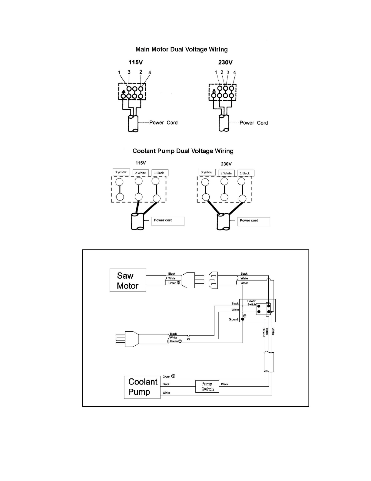
30
13.0 Electrical Connections – HVBS-712/712D Band Saw

31
14.0 Warranty and service
JET warrants every product it sells against manufacturers’ defects. If one of our tools needs service or repair, please
contact Technical Service by calling 1-800-274-6846, 8AM to 5PM CST, Monday through Friday.
Warranty Period
The general warranty lasts for the time period specified in the literature included with your product or on the official JET
branded website.
• JET products carry a limited warranty which varies in duration based upon the product. (See chart below)
• Accessories carry a limited warranty of one year from the date of receipt.
• Consumable items are defined as expendable parts or accessories expected to become inoperable within a
reasonable amount of use and are covered by a 90 day limited warranty against manufacturer’s defects.
Who is Covered
This warranty covers only the initial purchaser of the product from the date of delivery.
What is Covered
This warranty covers any defects in workmanship or materials subject to the limitations stated below. This warranty
does not cover failures due directly or indirectly to misuse, abuse, negligence or accidents, normal wear-and-tear,
improper repair, alterations or lack of maintenance. JET woodworking machinery is designed to be used with Wood.
Use of these machines in the processing of metal, plastics, or other materials outside recommended guidelines may
void the warranty. The exceptions are acrylics and other natural items that are made specifically for wood turning.
Warranty Limitations
Woodworking products with a Five Year Warranty that are used for commercial or industrial purposes default to a Two
Year Warranty. Please contact Technical Service at 1-800-274-6846 for further clarification.
How to Get Technical Support
Please contact Technical Service by calling 1-800-274-6846. Please note that you will be asked to provide proof
of initial purchase when calling. If a product requires further inspection, the Technical Service representative will
explain and assist with any additional action needed. JET has Authorized Service Centers located throughout the United
States. For the name of an Authorized Service Center in your area call 1-800-274-6846 or use the Service Center
Locator on the JET website.
More Information
JET is constantly adding new products. For complete, up-to-date product information, check with your local distributor
or visit the JET website.
How State Law Applies
This warranty gives you specific legal rights, subject to applicable state law.
Limitations on This Warranty
JET LIMITS ALL IMPLIED WARRANTIES TO THE PERIOD OF THE LIMITED WARRANTY FOR EACH PRODUCT.
EXCEPT AS STATED HEREIN, ANY IMPLIED WARRANTIES OF MERCHANTABILITY AND FITNESS FOR A
PARTICULAR PURPOSE ARE EXCLUDED. SOME STATES DO NOT ALLOW LIMITATIONS ON HOW LONG AN
IMPLIED WARRANTY LASTS, SO THE ABOVE LIMITATION MAY NOT APPLY TO YOU.
JET SHALL IN NO EVENT BE LIABLE FOR DEATH, INJURIES TO PERSONS OR PROPERTY, OR FOR
INCIDENTAL, CONTINGENT, SPECIAL, OR CONSEQUENTIAL DAMAGES ARISING FROM THE USE OF OUR
PRODUCTS. SOME STATES DO NOT ALLOW THE EXCLUSION OR LIMITATION OF INCIDENTAL OR
CONSEQUENTIAL DAMAGES, SO THE ABOVE LIMITATION OR EXCLUSION MAY NOT APPLY TO YOU.
JET sells through distributors only. The specifications listed in JET printed materials and on official JET website are
given as general information and are not binding. JET reserves the right to effect at any time, without prior notice, those
alterations to parts, fittings, and accessory equipment which they may deem necessary for any reason whatsoever.
JET
®
branded products are not sold in Canada by JPW Industries, Inc.
Product Listing with Warranty Period
90 Days – Parts; Consumable items
1 Year – Motors; Machine Accessories
2 Year – Metalworking Machinery; Electric Hoists, Electric Hoist Accessories; Woodworking Machinery used
for industrial or commercial purposes
5 Year – Woodworking Machinery
Limited Lifetime – JET Parallel clamps; VOLT Series Electric Hoists; Manual Hoists; Manual Hoist
Accessories; Shop Tools; Warehouse & Dock products; Hand Tools; Air Tools
NOTE: JET is a division of JPW Industries, Inc. References in this document to JET also apply to JPW Industries, Inc.,
or any of its successors in interest to the JET brand.

32
427 New Sanford Road
LaVergne, Tennessee 37086
Phone: 800-274-6848
www.jettools.com