
Loading ...
Loading ...
Loading ...
0.0
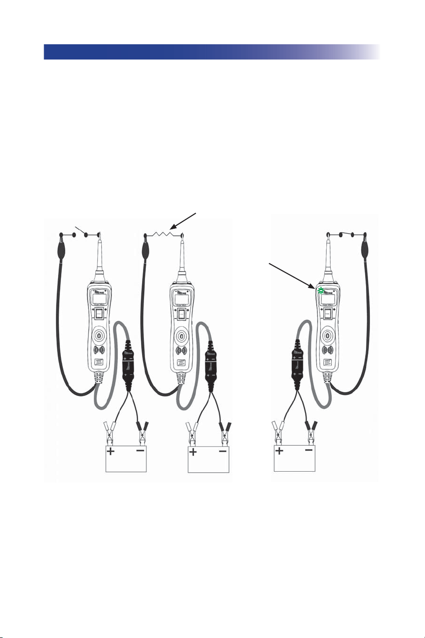
CONTINUITY TESTING (PPM)
While the PP3 is in Power Probe Mode, and by using the Power Probe tip in connection with chassis
ground or the auxiliary ground lead, continuity can be tested on wires and components attached or
disconnected from the vehicle’s electrical system.
The PP3 indicates continuity using 2 resistance levels. When the Power Probe tip has a resistance to
ground less than 20K Ohms but greater than 2K Ohms the LCD will indicate “0.0” volts but no
Green
“-” LED. But when the resistance to ground less than 2K Ohms the LCD will indicate “0.0” volts and
also the
Green “-” LED. The higher resistance continuity function is useful for checking Spark Plug
Wires, (disconnected from ignition) Solenoids and magnetic pickup coils, and the lower resistance
continuity for testing relay coils and wiring. However the best way to prove continuity of connec-
tions to either Ground or Battery is to power up the connection using the Power Switch. If the Circuit
Breaker trips you know that you have a good solid low resistance connection.
No Continuity
Continuity (less than 2 k Ω)
Green
5
0.0
Continuity (less than 20 k Ω
but greater than 2k Ω)
Loading ...
Loading ...
Loading ...