Loading ...
Loading ...
Loading ...
Installation Instructions
265 VOLT ELECTRICAL SUPPLY
/k WARNING:
Connection of this 965 V AC product to a branch circuit
MUST be done b) direct connection in accordance with
tile Natkmal Electric (;()de. Plugging this unit into a
building mounted exposed receptacle is not permitted
b) code.
These models must be installed using the apilropriate
GE power suppl} kit ti)r the branch circuit amperage
and the electrical resistance hearer wattage desired.
See the POWER CONNECTION (;HART in these
Installation Instructions. One of the ti)llowing
installation methods must be used:
A Elecu'ical subbase kits are a\_filable to provide a flexible
enclosm'e for direct c(mnecfion.
Branch Circuit and Proper GE Power
UnitAmperage Rating Subbase Kit SupplyKit
15 ILMZ204E15 1LM(5152
15 I_MZ204E15 ILM(5172
20 ILM4204E20 1LM(5202
30 ILM4204E30 1LM(5302
Tile instructions pr_wided wifll file selected subbase kit must
be cm'efid b ti)llo_vd. It is the responsibilit) of the installer
to ensm'e the connection of components is done in
accordance with these instructions and all electrical codes.
B For direct c(mnection to branch circuit wiring inskte the
provkted j unction box without using a subbase kit, cut
the cord, strip the wire ends and connect as ti)llo_:s.
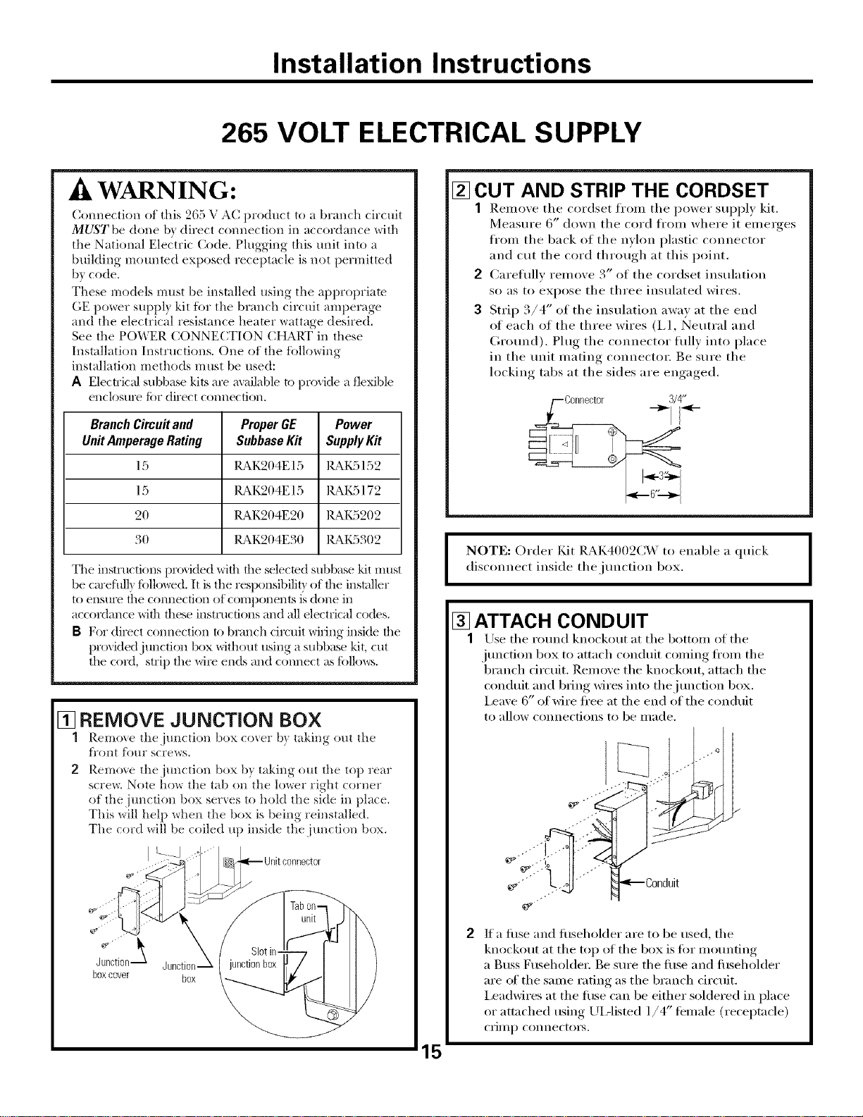
[] REMOVE JUNCTION BOX
1 Remo_e thejmlction box co_er b) taking out the
fl'ont Ibm" screws.
2 Remove thejmlction box by taking out the top rear
scre_. Note how the tab on the lower right corner
of the jtmction box serves to hold the side in place.
This will hel I) when the box is being reinstalled.
Tile cord will be coiled up inside thejmlction box.
Junction Junction-
boxcover box
[] CUT AND STRIP THE CORDSET
1 Remove tile cordset fl'om the power supply kit.
Measm'e 6" down the cord fl'om where it emerges
fl'om the back of the nylon plastic connector
and cut the cord through at tiffs point.
2 Carefidlv remove 3" of the cordset insulation
so as to expose the three insulated wires.
3 Strip 3/4" of the insulation away tat the end
of each of the three wires (I,1, Neutral and
Grotmd). Plug the connector fidlv into place
in the trait mating connectm: Be sure the
locking tabs at the sides are engaged.
3/4"
I NOTE: Order tCdt RAK4002(2('\ to enable a quick
disconnect inside tbejtmction box.
I
15
[] ATTACH CONDUIT
1 Use the rotmd knockout tattim bottom of tim
junction box to attach conduit coming fl'om tim
branch circuit. Remove the knockout, attach tim
conduit and bring wires into tbejtmction box.
I,eave 6" of wire fl'ee at the end of the conduit
to allow connections to be II/ade.
.o.-"
_"" ;..j._''" _-_Conduit
If a filse and fllseholder are to be used, the
knockout tat the top of the box is fi_r motmting
a Buss Fusel_oldet; Be sure the filse and filseholder
are of the same rating as the branch circuit.
I,eadwires at the filse can be either soldered in place
or am_ched using UiAisted 1/4" temale (receptacle)
ci'ili1 l) connectoi3.
Loading ...
Loading ...
Loading ...