Loading ...
IMPORTANT
For Non-ducted (Duct free) Installation:
a) Purchase non-ducted filter separately, model 41F.
b) Remove and discard damper/duct connector and grille cover
(See Step 3 in “Preparing the range Hood,” on page 3).
c) Follow all steps except steps inside dotted lines.
For Ducted Installation:
Follow all steps, including steps inside dotted lines.
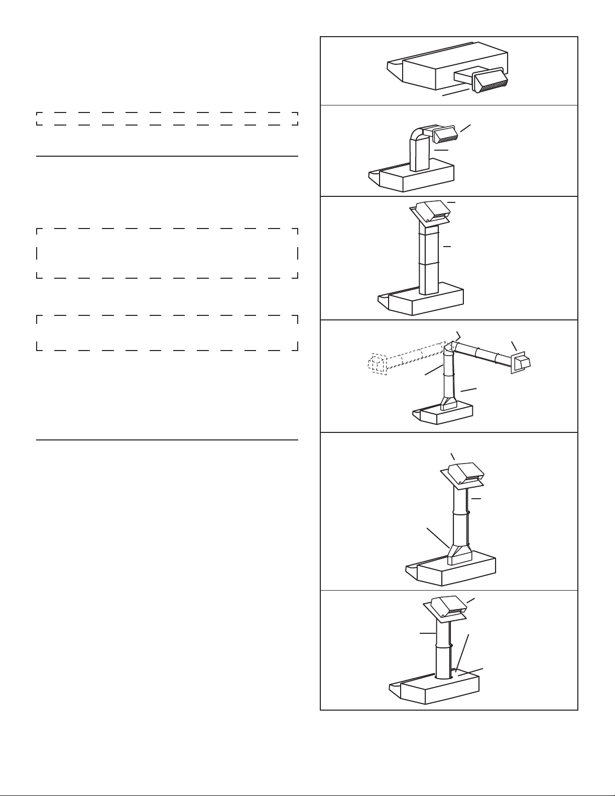
Begin planning ductwork by deciding where the duct will run between
the range hood and the outside. For best performance, use the shortest
possible duct run and a minimum number of elbows. There are several
choices shown - FIGS. 1A - 1F.
If needed, a 3¼” x 10” rectangular ducting range hood can be converted to
a round duct by means of a transition.
FIG. 1A. Ducting directly through the wall (for range hoods mounted on an
exterior wall). Shown are two ways to duct through an outside wall. If a wall
cap is used directly off the back of the hood, special care must be taken to
make sure that the damper in the damper/duct connector on the hood and
damper in the wall cap do not interfere with each other when the hood is
operating. This could result in either inadequate air delivery or back drafts.
If this condition does exist, remove the hood damper flap. Sometimes when
using a wall cap it is easier to duct vertically and then use an elbow as
shown in FIG. 1B.
FIG. 1C. Ducting straight up through the roof using 3¼” x 10” rectangular
duct. (For single story installations.)
FIG. 1D. Ducting between the ceiling joists (for multi-story installations) or
through the soffit space above the cabinets (where the soffit connects to
an outside wall).
FIG. 1E. Straight up through the roof using 3¼” x 10” to 6” round duct
transition and 6” round duct (for single-story installations).
FIG. 1F. Straight up through the roof using 7” round duct (for single-story
installations, 7” round adapter plate not included, part number SR680508).
PLANNING DUCTWORK INSTALLATION
TOOLS
Drill
1¼" Spade bit
Pliers
Flat blade and
Phillips screwdriver
Tape measure or ruler
and pencil
TOOLS AND MATERIAL REQUIRED
For ducted installations ONLY:
Saber saw
Metal snips
MATERIALS
Electrical wiring and supplies of type to comply with local codes
Roof or wall cap
Roof cement or caulk
Duct and metal foil duct tape
For installation on kitchen cabinets with recess bottoms only:
Two 1" x 2" x 12" (approximate length) wood strips (purchase locally)
Four 1¼" long flat heat wood screws (purchase locally) to fasten
strips to cabinet bottom
FIG. 1A
WALL CAP 639 OR 649
FIG. 1B
WALL CAP 639 OR 649
3¼” X 10” DUCT 401
FIG. 1C
ROOF CAP 634 OR 644
3¼” X 10” DUCT 401
FIG. 1D
ADJUSTABLE ELBOW 419
WALL CAP 641
3¼” X 10” TO 6” ROUND
DUCT
TRANSITION 411
6” ROUND DUCT 406
FIG. 1E
ROOF CAP 634 OR 644
6” ROUND DUCT 406
3¼” X 10” TO 6” ROUND
DUCT
TRANSITION 411
FIG. 1F
ROOF CAP 634 OR 644
7” ROUND DUCT 407
OPTIONAL DAMPER
MODEL BP87
7” ROUND DUCT PLATE
SR680508
- 2 -
Loading ...
Loading ...
Loading ...