OWNER'S MANUAL
CONTINUOUS PILOT
MODEL NO.
KWX - 3V
KWX - 4V
KWX - 5V
KWX - 6V
KWX - 7V
KWX - 8V
KWX - 9V
CAUTION
Read all instructions
carefullybefore starting
the installation.
Save this manual
for future reference.
These instructions must
be affixed on or adjacent
to the boiler.
Gas- Fired
Cast Iron
HOT WATER
BOILER
• Installation
• Operation
• Repair Parts
WAILING: Improper installation, adjustment, alteration, service or
maintenance can cause injury or property damage. Refer to this
manual. For assistance or additional information consult a qualified
installer, service agency or the gas supplier.
Sears, Roebuck and Co., Hoffman Estates, IL 60179 U.S.A I
KENNMORE CAST IRON BOILERS
FULL ONE YEAR WARRANTY ON HOT WATER AND GAS STEAM CAST IRON BOILERS
For one (1) year from the date of installation, when this boiler is installed and maintained in accordance
with our instructions. Sears willrepair defects in material or workmanship in the boiler,free of charge.
LIMITED 12 YEAR WARRANTY ON STEAM CAST IRON BOILERS
After one (1)year and through twelve (12)years from the date of installation,Sears willfurnish a replacement
heat exchanger, if the heat exchanger in the boiler is defective.YOU PAY FOR LABOR.
:_ LIMITED 20 YEAR WARRANTY ON HOT WATER CAST IRON BOILERS
After one (1)year and through twenty (20) years from thedate of installation,Sears willfurnish a replacement
heat exchanger ifthe heat exchanger in the boiler isdefective. YOU PAYFOR LABOR.
SEARS INSTALLATION WARRANTY
In addition to any warranty extended to you on the Sears merchandise involved,which warranty becomes
effective the date the merchandise is installed, should the workmanship of any Searsarranged installation
;_ prove faulty within one year, Sears will, upon notice from you, cause such faults to be corrected at
no additional cost to you.
FOR WARRANTY SERVICE, SIMPLY CONTACT THE NEAREST SEARS STORE OR SERVICE
;_l CENTER THROUGHOUT THE UNITED STATES. This warranty gives you specific legal rights, and
you may also haveother rights which vary from stateto state. i
IMPORTANT
The following are the responsibilities of the user and are not
covered by the Warranty
1. Filterclearing or replacement.
2. Damage to unit or unsatisfactory operation due to improper
cleaning or use of unit in corrosive atmosphere.
3. Damage to unit or unsatisfactoryoperation due to blown fuses
or inadequate or interrupted electrical protective devices.
4. Damage to unit caused by the use of components or other
accessories not compatible with the unit.
5. Ifthe unit is removed from the place it was originally installed,
this VCarrantybecomes void.
6. Damage to the unit caused by accident, abuse, negligence,
misuse, riot, fire,flood, or acts of God.
SEARS ROEBUCKAND COMPANY
D/817WA
Hoffman Estates,IL60179
1 Read the Owner's Manual for SafeOperation carefully Failure
to follow the rules for safe operation and the instructions can
cause a malfunction of the boiler and result in death, serious
bodily injury,and/or property damage.
2 Check your local cedes and utility requirements before
installation. The installation must be in acordance with their
directives.
3. Before servicing, allow boiler to cool. Always shut off any
electricity and gasto boiler when working on it.Thiswill prevent
any electrical shocks or burns.
4 Never test for gas leaks with an open flame. Use soap and
check all connections. This will avoid any possibility of fire
or explosion
5. Be certain your new boiler will be using the correct gas.
Overfiring will result in premature failure of the boiler sections
and cause dangerous operation
6. Never vent this boiler into an enclosed space. Always vent
to the outside.Never vent to anotherroom or inside a building
7. Be sure there isadequate air supply for complete combustion
8 Followa regular service and maintenance schedule forefficient
and safe operation.
2
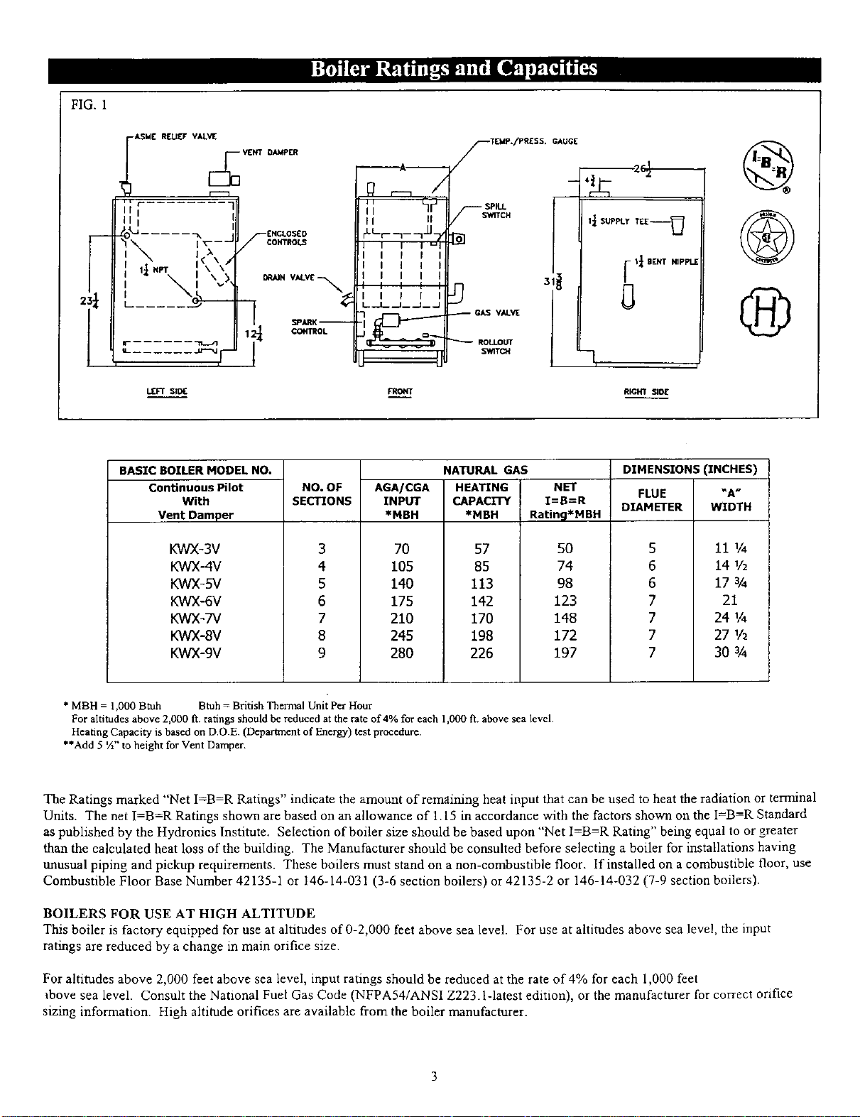
FIG. 1
r---
I
?
!
-ASME R[[J_¥ VALVE
C_ VI£NT
l
l
,-_ ..... -I,[_-----
J
i<\/
I;[ HPT ,\ \
"_ i \.A
L...... ,.Lr'--_l_ [
i
LEFT S;DE
DAMPER
ENCLOSED
SCOHTROL_
• _AJN VALVE %
COH_OL
--A u
hr_
I I II
II I
IIi
i I I
_._L_ _.1__ _1__ _
TEMP./PRESS. GAUGE
JIr' 'E'r'PPLE
31?
GAS VALVE
RIGHT SIO[
®
BASIC BOILER MODEL NO.
ConUnuous Pilot
With
Vent Damper
KWX-3V
KWX-4V
KWX-5V
KWX-6V
KWX-7V
KWX-8V
KWX-9V
NO. OF
SECTIONS
3
4
5
6
7
8
9
AGA/CGA
INPUT
*MBH
70
105
140
175
210
245
280
NATURAL GAS
HEATING
CAPACITY
*MBH
NET
I=B=R
Ratin9*MBH
5O
74
98
123
148
172
197
FLUE
DIAMETER
DIMENSIONS (INCHES)
"A"
WIDTH
57
85
113
142
170
198
226
5
6
6
7
7
7
7
11 1/4
14 1/2
17 ¾
21
24 1/4
27 1/2
30 ¾
* MBH = 1,000Btuh Btuh=British Thermal Unit PerHour a
For altitudes above 2,000 ft. ratings should be reduced at the rate of4_ for each 1,000ft. above sea level•
Heating Capacity is based on D.O.E (Deparirnentof Energy) test procedure.
**Add 5 ½" to height for Vent Damper.
The Ratings marked "Net I=B-R Ratings" indicate the amount of remaining heat input that can be used to heat the radiation or terminal
Units. The net I=B=R Ratings shown are based on an allowance of 1.15 in accordance with the factors shown on the I=B=R Standard
as published by the Hydronies Institute. Selection of boiler size should be based upon "Net I=B=R Rating" being equal to or greater
than the calculated heat loss of the building. The Manufacturer should be consulted before selecting a boiler for installations having
unusual piping and pickup requirements. These boilers must stand on a non-combustible floor. If installed on a combustible floor, use
Combustible Floor Base Number 42135-1 or 146-14-031 (3-6 section boilers) or 42135-2 or 146-14-032 (7-9 section boilers).
BOILERS FOR USE AT HIGH ALTITUDE
This boiler is factory equipped for use at altitudes of 0-2,000 feet above sea level. For use at altitudes above sea level, the input
ratings are reduced by a change in main orifice size.
For altitudes above 2,000 feet above sea level, input ratings should be reduced at the rate of 4% for each 1,000 feet
above sea level. Consult the National Fuel Gas Code (NFPA54/ANSI Z223.1-1atest edition), or the manufacturer for correct orifice
sizing information. High altitude orifices are available from the boiler manufacturer.
CheckIobesureyouhavetherightsizeboilerbeforestartingtheinstallation.
Seeratingandcapacitytableonpreviouspage.Alsobesurethenewboileris
forthetypeofgasyouareusing.Checktheratingplateontherightsideofthe
boiler.
Youmustseethattheboilerissuppliedwiththecorredtypeol gas,freshair
forcombustion,andasuitableelectricalsupply.Also,theboilermustbecon-
nectedtoasuitableventingsystemandanadequatepipingsystem.Finally,a
thermostat,properlylocated,isneededforcontroloftheheatingsystem.Ifyou
haveanydoubtsasto thevariousrequirements,checkwithlocalauthorities
andobtainprofessionalhelpwhereneeded.Takethetimetocompleteall of
thestepsforSAFEandPROPERoperationoftheheatingsystem.
Ifthisboilerisinstalledinabuildingunderconstruction,specialcaremustbe
takentoinsureacleancombustionairsupplyduringtheconstructionprocess.
Airborneparticulatessuchasfromdrywalldustandlromfiberglassinsulation
canclogtheburnerportsandcauseincompletecombustionandsooting.
Whererequiredbytheauthorityhavingjurisdiction,theinstallationmustcon-
formtoAmericanSocietyofMechanicalEngineersSafetyCodeforControl_
andSaletyDevicesforAutomaticallyFiredBoilers,No.CSD-1.
Theinstallationmustconformto therequirementsol theauthorityhaving
jurisdictionor,in theabsenceofsuchrequirements,totheNationalFuelGas
Code,ANSIZ223.1-1atestrevision.
Installers- Followlocalregulationswith respectto installationof CO
detectors.Followmaintenancerecommendationsin this instruction
manual.
Tecbniciens-Veuillezvousconformerd lareglementationenvigueur
coneemantI"installationdesdefecteursd'oxydedecarbone.Suivreles
consignesd'entretienfigurantdanslemanueldinstrudioncijoinL
IKEEP BOILER AREA CLEAN AND FREE FROM COMBUSTIBLE MATERIALS,
GASOLINE AND OTHER FLAMMABLE VAPORS AND LIQUIDS
1. Selecllevellocationascentralizedwithpipingsystem,andasnearchim-
ney,aspossible.
2. Placecratedboiler atselectedlocation,removecrateby pulling crate
sidesfromtopandbottomboards.Combustiblefloors:Whenboileristo
beinstalledona combustiblefloor,aSpecialBasePlatemustbeused-
146-14-031(2-6Section)or 146-14-032(7-9Section).Thisboilermust
notbeinstalledon carpeting.
3. Boileristo belevel.Metalshimsmaybeusedunderbaselegsforfinal
leveling.
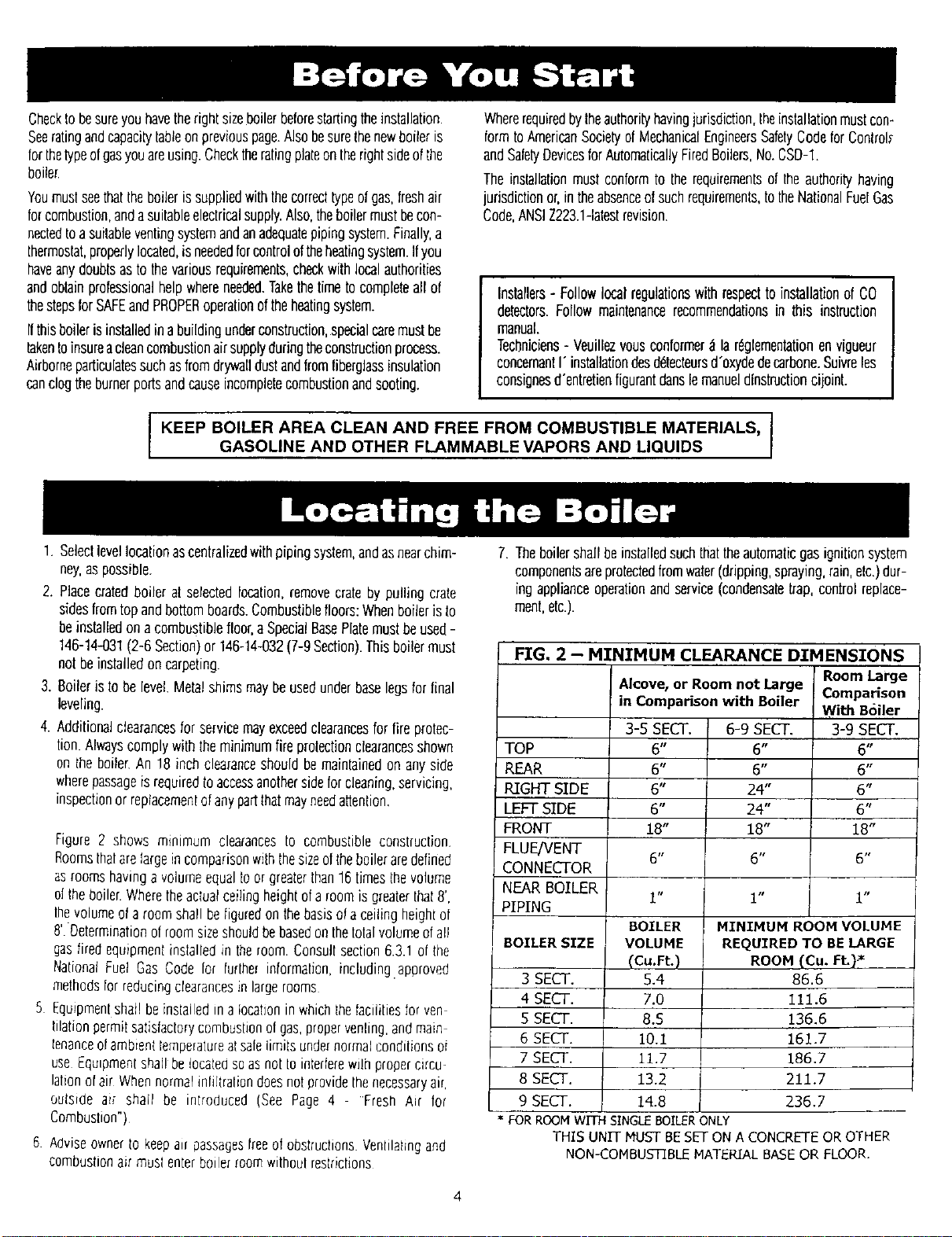
4. Additionalclearancesforservicemayexceedclearancesforfireprotec-
lion.Alwayscomplywithlhe minimumfireprolectionclearancesshown
on theboiler.An !8 inchclearanceshouldbemaintainedon anyside
wherepassageisrequiredtoaccessanothersideforcleaning,servicing,
inspectionor replacementofanypartthatmayneedattention.
Figure2 shows minimum clearancesto combustibleconstruction.
Roomsthatarelargeincomparisonwiththesizeoftheboileraredefined
asroomshavinga volumeequaltoor greaterthan16timesthevolume
ol theboiler.Wheretheactualceilingheightol a roomis greaterthat8',
lhevolumeol a roomshallbebguredon thebasisota ceilingheightof
8' Determinationofroomsizeshouldbebasedonthetotalvolumeofall
gasfiredequipmentinslalledin theroom.Consultsection6.3.1of the
NationalFuel GasCodelot furtherinlormatfon,including.approved
methods[orreducingclearancesin largerooms
5 Equipmentshat!beinstalledina locationin whichthetacibliesforyen
tilationpermitsatistaclorycembushenofgas,propervenbng,andmain
tenanceo!ambientlempe_alureatsafelimitsundernormalcondibonsoi
use£qulpmentshal!belocatedsoasnottointerferewdhpropercircu-
lationo[air Whennormalinlfltrabondoesnotprovidethenecessaryair,
outside ai_ shall be introduced (See Page 4 - Fresh Air for
Combusbon")
6 AdviseownerIo keepair passagesfreeofobstrucbons.VenblaPngand
combusbonair muslenterboilerroomwithoulreskictions
7. Theboilershallbeinstalledsuchthattheautomaticgasignitionsystem
componentsareprotectedfromwater(dripping,spraying,rain,etc.)dur-
ing applianceoperationandservice(condensatetrap,controlreplace-
ment,etc.).
FIG, 2 - MINIMUM
TOP
REAR
RIGHT SIDE
LEFT SIDE
FRONT
FLUE/VENT
CONNECTOR
NEAR BOILER
PIPING
BOILER SIZE
3 SECT.
4 SECT.
5 SECT.
6 SECT.
7 SECT.
8 SECT.
9 SECT.
CLEARANCE DTMENSIONS
Alcove, or Room not Large
in Comparison with Boiler
3-5 SECT.
6"
6"
6"
6"
18"
6 tl
i u
BOILER
VOLUME
(Cu.Ft.)
5.4
7.0
8.5
10.1
11.7
13.2
14.8
6-9SECT.
6"
6"
24"
24"
18"
rq
Room Large
Comparison
With B6iier
3-9 SECT.
6"
6"
6"
6"
18"
6 t,
1" 1"
MINIMUM ROOM VOLUME
REQUIRED TO BE LARGE
ROOM (Cu. Ft.) _
86.6
111.6
136.6
161.7
186.7
211.7
236,7
FOR ROOM WITH SINGLE BOILER ONLY
THIS UNIT MUST BE SET ON A CONCRETE OR OTHER
NON-COMBUSTIBLE MATERIAL BASE OR FLOOR.
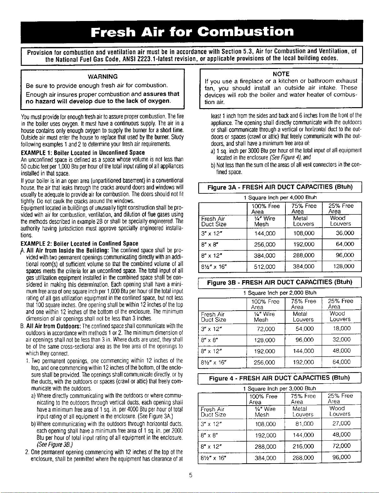
IProvision for combustionand ventilation air must be in accordance with Section5.3, Air for Combustionand Ventilation, of
the National Fuel Gas Code, ANSI Z223.1-1atest revision, or applicable provisionsof the local building codes.
WARNING
Be sure to provide enough fresh air for combustion.
Enough air insures proper combustion and assures that
no hazard will develop due to the lack of oxygen.
Youmustprovideforenoughfreshairtoassurepropercombustion.Thefire
in theboilerusesoxygen.It musthaveacontinuoussupply.Theair in a
housecontainsonlyenoughoxygentosupplylhe burnerforashorttime.
Outsideair mustenterthehousetoreplacethatusedbytheburner.Study
followingexamples1and2 todetermineyourfreshair requirements.
EXAMPLE1: BoilerLocatedin UnconfinedSpace
Anunconfinedspaceisdefinedasaspacewhosevolumeis notlessthan
50cubicfeelper1,000Bluperhourofthelotalinputratingofallappliances
installedin thatspace.
Ifyourboilerisinanopenarea(unpartitiouedbasement)in aconventional
house,theairthatleaksthroughthecracksarounddoorsandwindowswill
usuallybeadequatetoprovideair forcombustion.Thedoorsshouldnotfit
tightly.Donotcaulkthecracksaroundthewindows.
Equipmentlocatedin buildingsofunusuallytightconstructionshallbepro-
videdwith airforcombustion,ventilation,anddilutionol fluegasesusing
themethodsdescribedin example2Borshallbespeciallyengineered.The
authorityhavingjurisdictionmustapprovespeciallyengineeredinstalla-
tions.
EXAMPLE2: BoilerLocatedin ConfinedSpace
/L All Air from Insidethe Building:Theconfinedspaceshallbepro-
videdwithtwopermanentopeningscommunicatingdirectlywithanaddi-
tionalroom(s)of sufficientvolumesothatthecombinedvolumeof all
spacesmeetsthecriteriafor anunconfinedspace.Thetotalinputofall
gas:utilizationequipmentinstalledin thecombinedspaceshallbecon-
sideredin makingthis determination.Eachopeningshallhavea mini-
mumfreeareaofonesquareinchper1,000Btuperhourolthetotalinput
ratingofall gasutilizationequipmentin theconfinedspace,butnotless
that100squareinches.Oneopeningshallbewithin12inchesofthetop
andonewithin12 inchesofthebottomoftheenclosure.Theminimum
dimensionofairopeningsshallnolbelessthan3 inches.
B.AllAirfrom Outdoors:Theconfinedspaceshallcommunicatewiththe
outdoorsinaccordancewithmethods1or 2.Theminimumdimensionof
airopeningsshallnotbelessthan3 in.Whereductsareused,theyshall
beof thesamecross-sectionalareaasthefreeareaoftheopeningsto
whichtheyconnect.
1.Twopermanentopenings,onecommencingwithin 12 inchesof the
top,andonecommencingwithin12inchesoftheboltom,oltheenclo-
sureshallbeprovided.Theopeningsshallcommunicatedirectly,orby
theducts,withtheoutdoorsor spaces(crawlor attic)thaifreelycom-
municatewiththeouldoors.
a)Wheredirectlycommunicatingwiththeoutdoorsor wherecommu-
nicatingtotheoutdoorsthroughverticalducts,eachopeningshag
haveaminimumtreeareaof1sq. in.per4000Btuperhouroftotal
inputratingofall equipmentin theenclosure.(SeeFigure3A.)
b)Wherecommunicatingwiththeoutdoorsthroughhorizontalducts,
eachopeningshal!havea minimumfreeareaof 1sq.in. per2000
Blu perhouroftotalinputratingofall equipmentin theenclosure.
(SeeFigure3B.)
2.Onepermanentopeningcommencingwith12 inchesofthelop ofthe
enclosure,shallbepermittedwheretheequipmenthasclearanceofat
NOTE
If you use a fireplace or a kitchen or bathroom exhaust
fan, you should install an outside air intake. These
devices will rob the boiler and water heater of combus-
tion air.
least1 inchfromthesidesandbackand6 incheslromIhefronlofthe
appliance.TheopeningshalldirectlycommunicatewithIheoutdoors
or shallcommunicatethrougha verticalor horizonlalducttotheoub
doorsor spaces(crawlor attic)thatfreelycommunicatewiththeout-
doors,andshallhaveaminimumfreeareaof:
a) 1sq. inchper3000Btuperhourol theIolalinputofaftequipment
locatedin lheenclosure(SeeFigure4),and
b)Notlessthanthesumoftheareasofallvenlconnectorsinthecon-
finedspace.
Figure 3A - FRESH AIR DUCT CAPACITIES (Btuh) i
Fresh Air
Duct Size
3"x 12"
8" x8"
8" X 12"
81/2"X 16"
1Square Inch per 4,000 Btuh
100% Free 75% Free
Area Area
1/4"Wire Metal
Mesh Louvers
144,000 108,000
256,000 192,000
384,000 288,000
512,000 384,000
25% Free
Area
Wood
Louvers
36,000
64,000
96,000
128.000
I3B - FRESH AIR DUCT CAPACITIES (Btuh) I
Figure
1Square Inch per2,000 Btuh
Fresh Air
Duct Size
3" x 12"
! 8" x 8"
8"x 12"
81/2"x 16"
100% Free 75% Free
Area Area
V4"Wire Metal
Mesh Louvers
72,000 54,000
128,000 96,000
192,000 144,000
256,000 192,000
25% Free
Area
Wood
Louvers
18,000
32,000
48,000
64,000
IFRESH AIR DUCT CAPACITIES (Btuh) i
I
Figure 4
1 Square Inch per 3,000 Bruh
100% Free 75% Free 25% Free
Area Area Area
Fresh Air V,¢'Wire Metal Wood
Duct Size Mesh Louvers Louvers
3" x 12" 108,000 81,000 27,000
8" x 8" 192,000 144,000 48,000
8" x 12" 288,000 216,000 72,000
8V2"x 18" 384,000 288,000 96,000
5

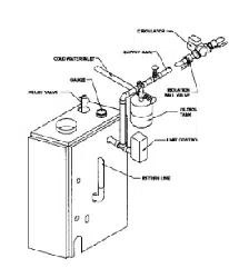
1.PlaceboilerintheselecledIocalion(asnearchimneyaspossible.)Your
boilerisshippedassembled.YouneedonlyIoinsfalltheReliefValveand
adrainlinetocarryanywalerorsteamIoadrain.
2.InstallRelielValveintothe3/,,-pipeonthetopol Iheboiler.SeeFigure5.
Use¾" Pipeandanelbow(nolfurnished)tocarrythewalerorsteamto
anearbydrain.Donotconnectdirectlytoadrainbulleaveanairgap.No
shutollol anydescriptionshallbeplacedbetweenthesafdyrebelvalve
andtheboiler,or ondischargepipesbetweensuchsafetyvalvesandthe
atmosphere.Installationol thesafetyrelielvalveshallconformto the
requirementsof the ANSI/ASMEBoiler and PressureVesselCode,
SeclionIV.Themanulactureris notresponsibleforanywaterdamage.
InstallDrainValvein lowerleftsideofboilerasmarked.
3.ConnectSupplyandReturnLinestoboiler.Theconneclionsmayrequire
certainadditionalfiltingsandparts,asshownondiagram(Figs.5and6).
4.Thisboileris equippedwilh 11/4"supplyandreturnconnectionsonboth
theleftandrightsidesol theboiler.
Inconnectingthecoldwatersupplytothewalerinlelvalve,makesurethat
a cleanwalersupplyis available.Whenthewatersupplyis froma weftor
pump,asandstrainershouldbeinstalledatthepump.
A hotwalerboiler installedaboveradiationlevelmustbeequippedwilha
lowwatercutoffdevice.A periodicinspectionisnecessary,asisflushingof
floattypedevices,permanufacturersspecificinstruction.
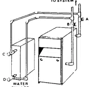
FOR USE WITH COOUNG UNITS
A. Thisboiler,whenusedinconnectionwithchilledwatersystems,mustbe
installedso that thechilledwateris pipedin parallelwiththeheating
boiler.Appropriatevalvesmustbeused1oprevenlthechilledwaterfrom
enteringtheheatingboiler(Fig.6).
B. Whenthisboiler is connectedto heatingcoils locatedin air handling
unitswheretheymaybeexposedtorefrigeratedaircirculation,thepip-
ing syslemshallbeequippedwithflowcontrolvalvesorotherautomaf-
icmeanstoprevenlgravgycirculationoftheboilerwalerduringthecool-
ing cycle.
LOW DESIGN WATER TEMPERATURE SYSTEMS
(BELOW 140°)
If Iheboileristobeusedin aheatingsysfemwheredesignwaterlempera-
luresbelow140° Faredesired(e.g.radianlfloorhealing),a3-wayor4-way
mixingvalveor suitablealternativeis requiredtopreventlowfemperature
returnwaterfromenleringtheboiler.FollowIhemixingvalvemanufacturer's
installationinstructions.
TheminimumdesignreturnwaterLemperatureIotheboilertoprevenlcon-
densationin theboilerandventingis120° E Theminimumhigh limilset-
tingis 140° F.
I CAUTION
THE ISOLATION BALL VALVES CONTAIN TEFLON
SEATS AND SEALS. OVERHEATING THIS VALVE
MAY CAUSE PREMATURE FAILURE.
COt.o WATE_ LNLET.
VALVES A & B
OPEN FOR HEATING;
CLOSE FOR COOLING
VALVES C & O
CLOSE FOR HEATING:
OPEN FOR COOLING
TO SYSTEM
cd
WAFER
CHILLER
For boilers for connection to gas vents or chimneys, vent Installations shall be
in accordance with Part 7, Venting of Equipment, of the National Fue| Gas Code,
ANSI Z223.1-1atest revision and applicable provisions of the local building codes.
CHIMNEY SIZING
CHECK YOUR CHIMNEY
Thisis a very imporfantpartof yourheatingsystem It mustbe clean,
therightsize,properlyconstructedandin GOODCONDITIONNo boiler
canlunctionproperlywith a bad chimney.Fig. 7 givestypicalchimney
sizes.Fig.8 givesyouanideahowaboilermightbe ventedto achimney
Nofetha_theheight(HT)ismeasuredfromtheventpipetothelop.
Chimneysizing,and all otheraspectsof the vent installationmustbe
in accordancewith Part7 of the NationalFuelGasCode,ANSIZ223.1
- laleslrevision,andapplicableprovisionsofthelocalbuildingcodes.
In Canada,follow CSA B149.1and B149.2,InstallabonCodesfor
GasBurningAppliancesandEquipment.
6
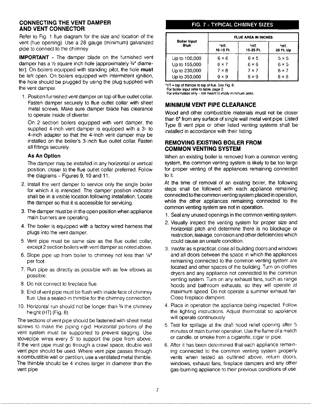
CONNECTING THE VENT DAMPER
AND VENT CONNECTOR
Refer to Fig. 1 flue diagram for the size and location of the
vent (flue opening). Use a 28 gauge (minimum) galvanized
pipe to connect to the chimney
IMPORTANT - The damper blade on the furnished vent
damper has a !/2square inch hole (approximately 3/4"diame-
ter). On boilers equipped with standing pilot, the hole must
be left open. On boilers equipped with intermittent ignition,
the hole should be plugged by using the plug supplied with
the vent damper.
1. Position furnished vent damper on top of flue outlet collar.
Fasten damper securely to flue outlet collar with sheet
metal screws. Make sure damper blade has clearance
to operate inside of diverter.
On 2 section boilers equipped with vent damper, the
supplied 4-inch vent damper is equipped with a 3- to
4-inch adapter so that the 4-inch vent damper may be
installed on the boiler's 3-inch flue outlet collar. Fasten
all fittings securely
As An Option
The damper may be installed in any horizontal or vertical
position, closer to the flue outlet collar preferred. Follow
the diagrams - Figures 9, 10 and 11.
2. Install the vent damper to service only the single boiler
for which it is intended. The damper position indicator
shall be in a visible location following installation. Locate
the damper so that it is accessible for servicing.
3. The damper must be in the open position when appliance
main burners are operating.
4. The boiler is equipped with a factory wired harness that
plugs into the vent damper.
5. Vent pipe must be same size as the flue outlet collar,
except 2 section boilers with vent damper as noted above.
6. Slope pipe up from boiler to chimney not less than V4"
per foot.
7. Run pipe as directly as possible with as few elbows as
possible.
8. Do not connect to fireplace flue.
9. End of vent pipe must be flush with inside face of chimney
flue. Use a sealed-in thimble for the chimney connection.
10. Horizontal run should not be longer than 3/4the chimney
height (HT) (Fig. 8)
The sections of vent pipe should be fastened with sheet metal
screws to make the piping rigid. Horizontal portions of the
vent system must be supported to prevent sagging. Use
stovepipe wires every 5' to support the pipe from above.
If the vent pipe must go through a crawl space, double wall
vent pipe should be used. Where vent pipe passes through
a combustible wall or partition, use a ventilated metal thimble.
_he thimble should be 4 inches larger in diameter than the
vent pipe
Boiler Input
Btuh
Up to 100,000
Up to 155,000
Up to 230,000
Up to 350,000
"HT
10-15 Ft.
6x6
6x7
7x8
9x9
FLUE AREA IN INCHES
"HT.
15-25 Ft.
6x5
6x6
7x7
8x9
"HT
25 Ft Up
5×5
6×5
6×7
8×8
"HT - top of thimble to top of flue. See F_g 8.
For boiler input refer to table, page 2
For intormaliOn only - no{ meant to imply minimum s_zes
MINIMUM VENT PIPE CLEARANCE
Wood and other combustible materials must not be closer
than 6" from any surface of single wall metal vent pipe. Listed
Type B vent pipe or other listed venting systems shall be
installed in accordance with their listing.
REMOVING EXISTING BOILER FROM
COMMON VENTING SYSTEM
When an existing boiler is removed from a common venting
system, the common venting system is likely to be too large
for proper venting of the appliances remaining connected
to it.
At the time of removal of an existing boiler, the following
steps shall be followed with each appliance remaining
connected tothe common venting system placed in operation,
while the other appliances remaining connected to the
common venting system are not in operation.
1. Seal any unused openings in the common venting system.
2. Visually inspect the venting system for proper size and
horizontal pitch and determine there is no blockage or
restriction, leakage, corrosion and other deficiencies which
could cause an unsafe condition.
3. Insofar as ispractical, close all building doors and windows
and all doors between the space in which the appliances
remaining connected to the common venting system are
located and other spaces of the building. Turn on clothes
dryers and any appliance not connected to the common
venting system. Turn on any exhaust fans, such as range
hoods and bathroom exhausts, so they will operate at
maximum speed. Do not operate a summer exhaust fan
Close fireplace dampers
4. Place in operation the appliance being inspected. Follow
the lighting instructions Adjust thermostat so appliance
will operate continuously.
5 Test for spillage at the draft hood relief opening after 5
minutes of main burner operation. Use the flame of a match
or candle, or smoke from a cigarette, cigar or pipe
6. After it has been determined that each appliance remain-
ing connected to the common venting system properly
vents when tested as outlined above, return doors,
windows, exhaust fans, fireplace dampers and any other
gas-burning appliance to their previous conditions of use.

7Any _mproper operation of the common venting system
should be corrected so the installation conforms with the
National Fuel Gas Code, ANSI Z223.1 -latest revision. When
res_ztng any portion of the common venting system, the
common venting system should be resized to approach
the minimum size as determined using the appropriate
tables in Part 11 in the National Fue! Gas Code, ANSI
Z2231-latest revision
For boilers for connection to gas vents or chimneys,
vent installations shall be in accordance with Part 7,
Venting of Equipment, of the National Fuel Gas Code,
ANSI Z223.1-1atest revision and applicable provisions
of the local building codes.
Vent connectors serving appliances vented by natural
draft shall not be connected into any portion of
mechanical draft systems operating under positive
pressure.
ROOF
RIDGE
3/4 HT MAXIMUM
HT
'MUST SLOPE UP
AT LEAST 1/4 INCH
PER FOOT OF
HORIZONTAL RUN
HORIZONTAL INSTALLATION
FLOW _NO
TO FURNACE VENT TO CHIMNEY
OR BOILER DAMPER INSTALL VENT DAMPER WITH
ACTUATOR TO SIDES OF
VENT ONLY. DO NOT MOUNT
ABOVE OR BELOW VENT
VERTICAL INSTALLATION
TO CHIMNEY
FLOW VENT
DAMPER ACTUATOR MAY BE
TO FURNACE_ iNSTALLEDIN ANY POSITION
OR BOILER U
C_N: IX) NOT INSTALL
THE VENT DAMPER
WITHIN 6 in. (152 mm) OF
COMBUS33BLE MATERIAL
3HIMNEY
BOILER WATER HEATER
TYPICAL INSTALLA'nON FOR VENT DAMPER
NOTE CAUTION AND FOOTNOTES
1Installthe vent damper to service only the single ap_iance for
which it is intended,if improperly installed,ahazardous cond_on,
such as an explosionorcarbon monoxide pe,,sening,could result.
2_ Do not install the vent damper on vent pipecurve.
3 Do not run wires near high temperature surfaces. Use staed_ff
brackets Jfnecessary
8
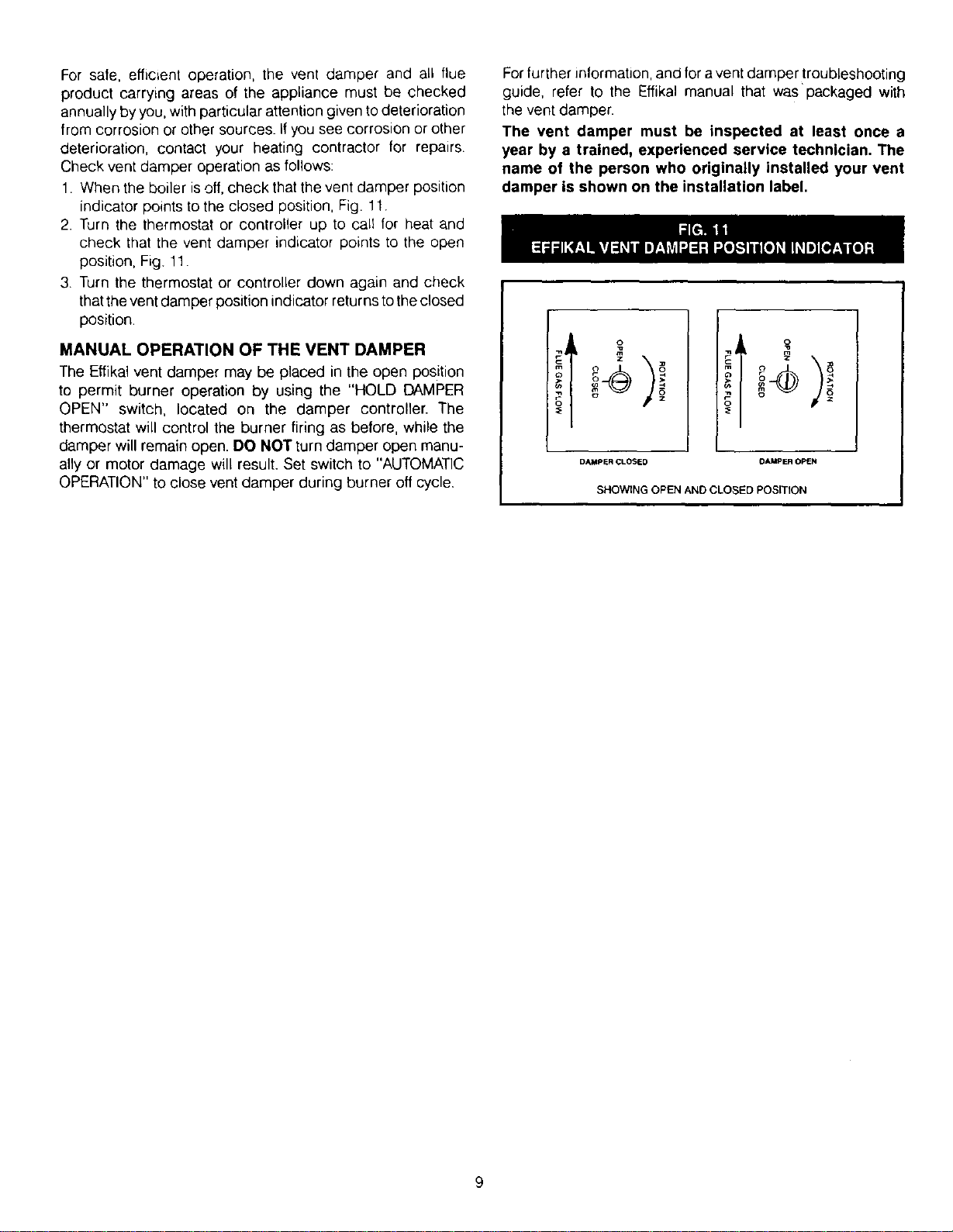
Forsafe,efficientoperation,the vent damper and all flue
product carrying areas of the appliance must be checked
annually by you, with particular attention given to deterioration
from corrosion or other sources. If you see corrosion or other
deterioration, contact your heating contractor tor repairs.
Check vent damper operation as follows:
1. When the boiler isoff, check that the vent damper position
indicator points to the closed position, Fig. 11.
2. Turn the thermostat or controller up to call for heat and
check that the vent damper indicator points to the open
position, Fig. 11.
3. Turn the thermostat or controller down again and check
that the vent damper position indicator returns to the closed
position.
MANUAL OPERATION OF THE VENT DAMPER
The Effikal vent damper may be placed in the open position
to permit burner operation by using the "HOLD DAMPER
OPEN" switch, located on the damper controller. The
thermostat will control the burner firing as before, while the
damper will remain open. DO NOT turn damper open manu-
ally or motor damage will result. Set switch to "AUTOMATIC
OPERATION" to close vent damper during burner off cycle.
Forfurther information,and for a vent damper !roubleshooting
guide, refer to the Effikal manual that was packaged with
the vent damper.
The vent damper must be inspected at least once a
year by a trained, experienced service technician, The
name of the person who originally installed your vent
damper is shown on the installation label,
iI 010
i6 ° °1
DAMPER CLOSED OAMPER OPEN
SHOWING OPEN AND CLOSED POSmON
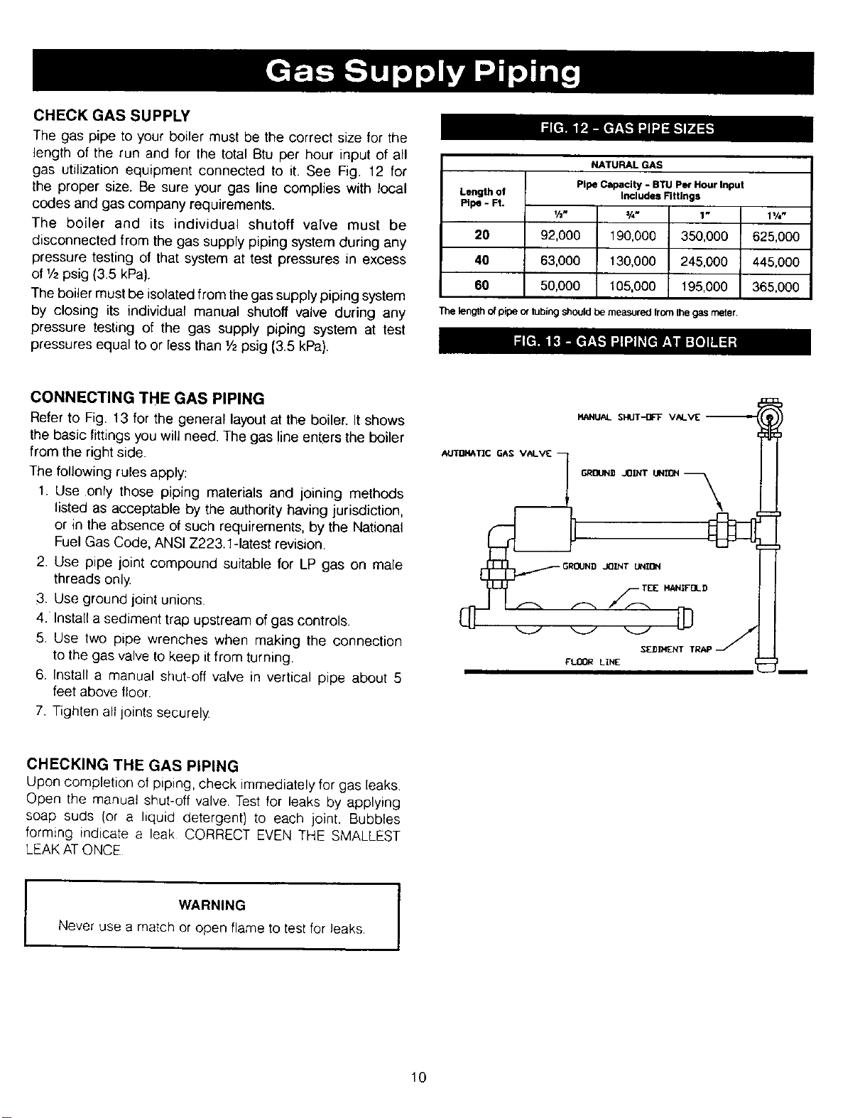
CHECK GASSUPP_
The gas pipe to your boiler must be the correct size for the
length of the run and for the total Btu per hour input of all
gas utilization equipment connected to it. See Fig. 12 for
the proper size. Be sure your gas line complies with local
codes and gas company requirements.
The boiler and its individual shutoff valve must be
disconnected from the gas supply piping system during any
pressure testing of that system at test pressures in excess
of I/2psig (3.5 kPa).
The boiler must be isolated from the gas supply piping system
by closing its individual manual shutoff valve during any
pressure testing of the gas supply piping system at test
pressures equal to or less than 1/zpsig (3.5 kPa).
NATURALGAS
PipeCapacity -BTU per Hour Input
Length of Includes Fittings
Pipe-Ft. V2" 3/4" 1" 11/4"
20 92,000 190,000 350,000 625,000
40 63,000 130,000 245,000 445,000
60 50,000 105,000 195,000 365,000
The length of pipe of tubing should be measured from the gas meter
CONNECTING THE GAS PIPING
Refer to Fig. 13 for the general layout at the boiler. It shows
the basic fittings you will need. The gas line enters the boiler
from the right side.
The following rules apply:
1. Use only those piping materials and joining methods
listed as acceptable by the authority having jurisdiction,
or in the absence of such requirements, by the National
Fuel Gas Code, ANSI Z223.1-1atest revision.
2. Use pipe joint compound suitable for LP gas on male
threads only
3. Use ground joint unions.
4.Install a sediment trap upstream of gas controls.
5. Use two pLpe wrenches when making the connection
to the gas valve to keep it from turning.
6. Install a manual shut-off valve in vertical pipe about 5
feet above floor.
7 Tighten all joints securely
CHECKING THE GAS PIPING
Upon completion of piping, check immediately for gas leaks
Open the manual shut-off valve. Test for leaks by applying
soap suds (or a liquid detergent) to each joint. Bubbles
forming indicate a leak CORRECT EVEN THE SMALLEST
LEAK ATONCE
WARNING
Never use a match or open flame to test for leaks.
10
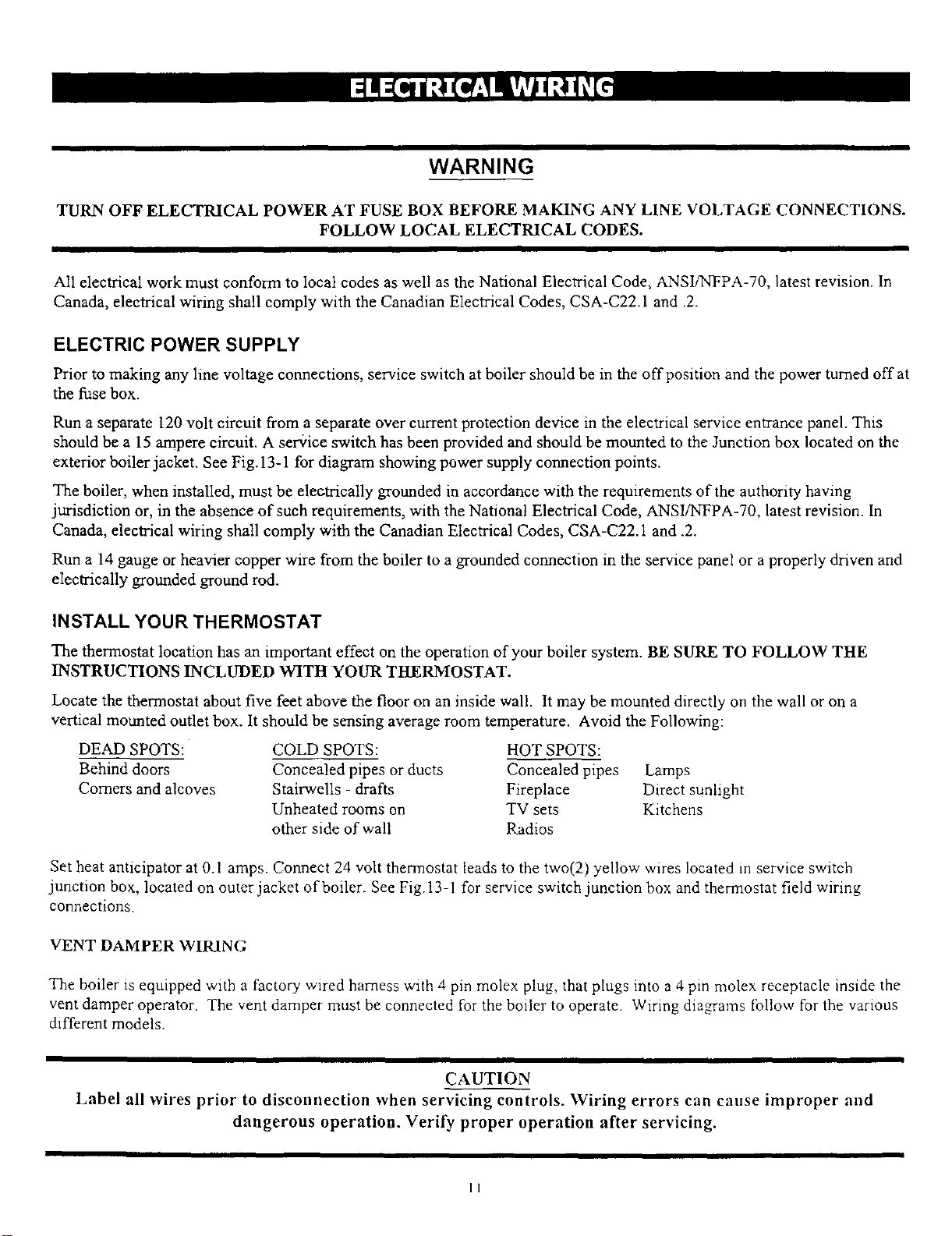
WARNING
TURN OFF ELECTRICAL POWER AT FUSE BOX BEFORE MAKING ANY LINE VOLTAGE CONNECTIONS.
FOLLOW LOCAL ELECTRICAL CODES.
II I
All electrical work must conform to local codes as well as the National Electrical Code, ANSI/NFPA-70, latest revision. In
Canada, electrical wiring shall comply with the Canadian Electrical Codes, CSA-C22.1 and .2.
ELECTRIC POWER SUPPLY
Prior to making any line voltage connections, service switch at boiler should be in the offpnsition and the power turned offat
the fuse box.
Run a separate 120 volt circuit from a separate over current protection device in the electrical service entrance panel. This
should be a 15 ampere circuit. A ser+ice switch has been provided and should be mounted to the Junction box located on the
exterior boiler jacket. See Fig. 13-1 for diagram showing power supply connection points.
The boiler, when installed, must be eleotrically grounded in accordance with the requirements of the authority having
jurisdiction or, in the absence of such requirements, with the National Electrical Code, ANSI/NFPA-70, latest revision. In
Canada, electrical wiring shall comply with the Canadian Electrical Codes, CSA-C22.1 and .2.
Run a 14 gauge or heavier copper wire from the boiler to a grounded connection in the service panel or a properly driven and
electrically grounded ground rod.
INSTALL YOUR THERMOSTAT
The thermostat location has an important effect on the operation of your boiler system. BE SURE TO FOLLOW THE
INSTRUCTIONS INCLUDED WITH YOUR THERMOSTAT.
Locate the thermostat about five feet above the floor on an inside wall. It may be mounted directly on the wall or on a
vertical mounted outlet box. It should be sensing average room temperature. Avoid the Following:
DEAD SPOTS:
Behind doors
Comers and alcoves
COLD SPOTS:
Concealed pipes or ducts
Stairwells - drafts
Unheated rooms on
other side of wall
HOT SPOTS:
Concealed pipes Lamps
Fireplace Direct sunlight
TV sets Kitchens
Radios
Set heat anticipator at 0.1 amps. Connect 24 volt thermostat leads to the two(2) yellow wires located in service switch
junction box, located on outer jacket of boiler. See Fig.13-1 for service switch junction box and thermostat field wiring
connections.
VENT DAMPER WIRING
The boiler is equipped with a factory wired harness with 4 pin molex plug, that plugs into a 4 pin molex receptacle inside the
vent damper operator. The vent damper must be connected for the boiler to operate. Wiring diagrams follow for the various
different models.
CAUTION
Label all wires prior to disconnection when servicing controls. Wiring errors can cause improper and
dangerous operation. Verify proper operation after servicing.
11
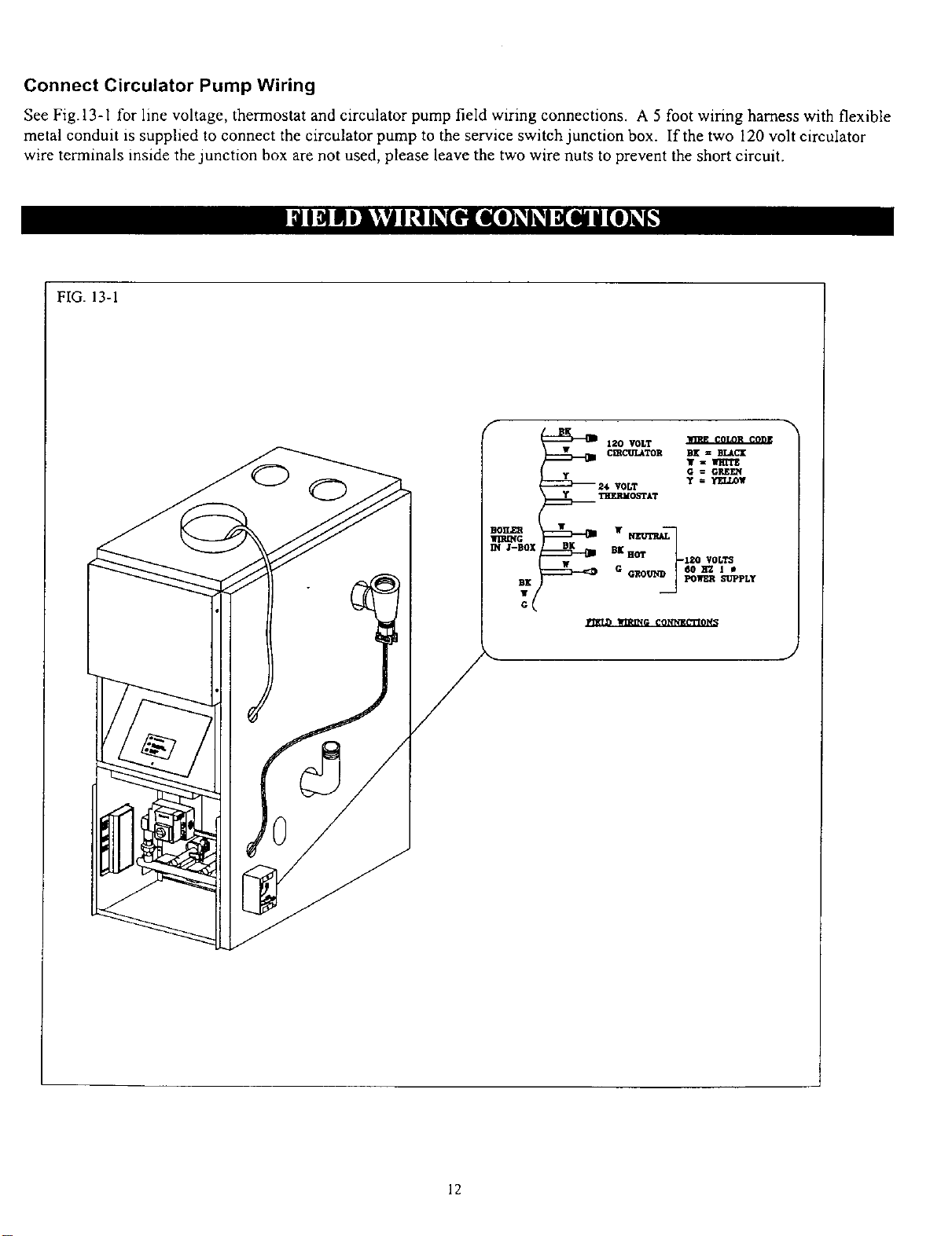
Connect Circulator Pump Wiring
See Fig.13-1 for line voltage, thermostat and circulator pump field wiring connections. A 5 foot wiring harness with flexible
metal conduit is supplied to connect the circulator pump to the service switch junction box. If the two 120 volt circulator
wire terminals inside the junction box are not used, please leave the two wire nuts to prevent the short circuit.
FIG. 13-1
12

ITHIS PAGE INTENTIONALLY LEFT BLANK I
13
THIS PAGE INTENTIONALLY LEFT BLANK J
14
GROUNO ¢
115VAC __
POWER , --
suP_¥.OT......... --_ _H______
NELrmAL [
ir .....
ii
III
I
I
ClRCU_TOR _J'J_
PUMP 2€V _ERMOSrAT
81
24 '_0LT TRANSFORMER
I
WXF._MR PRl_/ BU
[3 Q
Y I
_ IFL_I LOCK_ VENT
_ SHUT OR=
EROLLOUT
ySA,_L'IYSHUT OFF
OR
OR
TwBK
L BK l
AQUASTAT
OR
BOILER SENSOR
GAS VALVlEVR8200A/VR830OA
BK
MAIN POWER STATUS LIGHT
CALL FOR HEAT/CIRCULATOR PUMP STATUS LIGHT
GAS VALVE/BURNER STATUS LIGHT
WIRE CODE COLOR COOE
DAMPER CABLE BK-BLACK
BIR-BROWN
-- LINE VOLTAGE P -PINK
.... LINE VOLTAGE Y -YELLOW
FIELD WIRING R-RED
W -WRITE
-- LOW VOLTAGE G -GREEN
.... LOW VOLTAGE GY -GRAY
FIELD WIRING
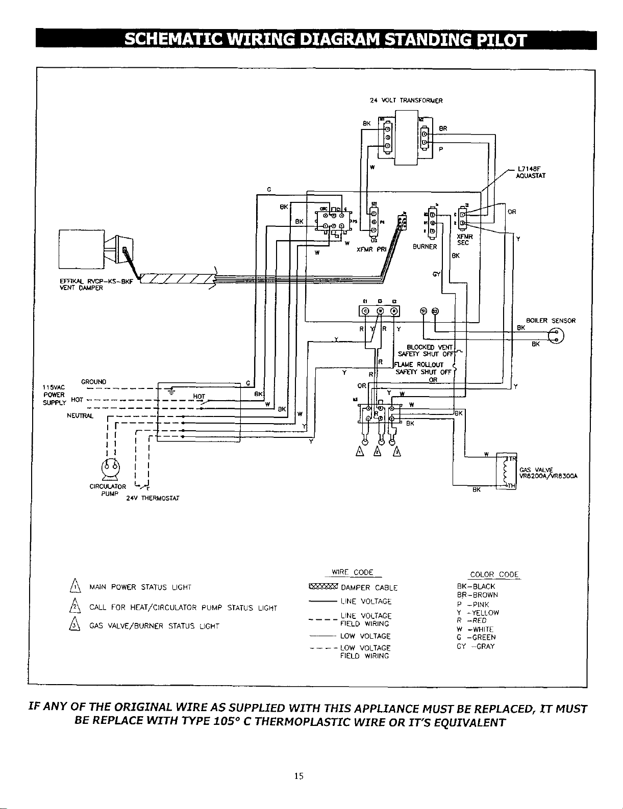
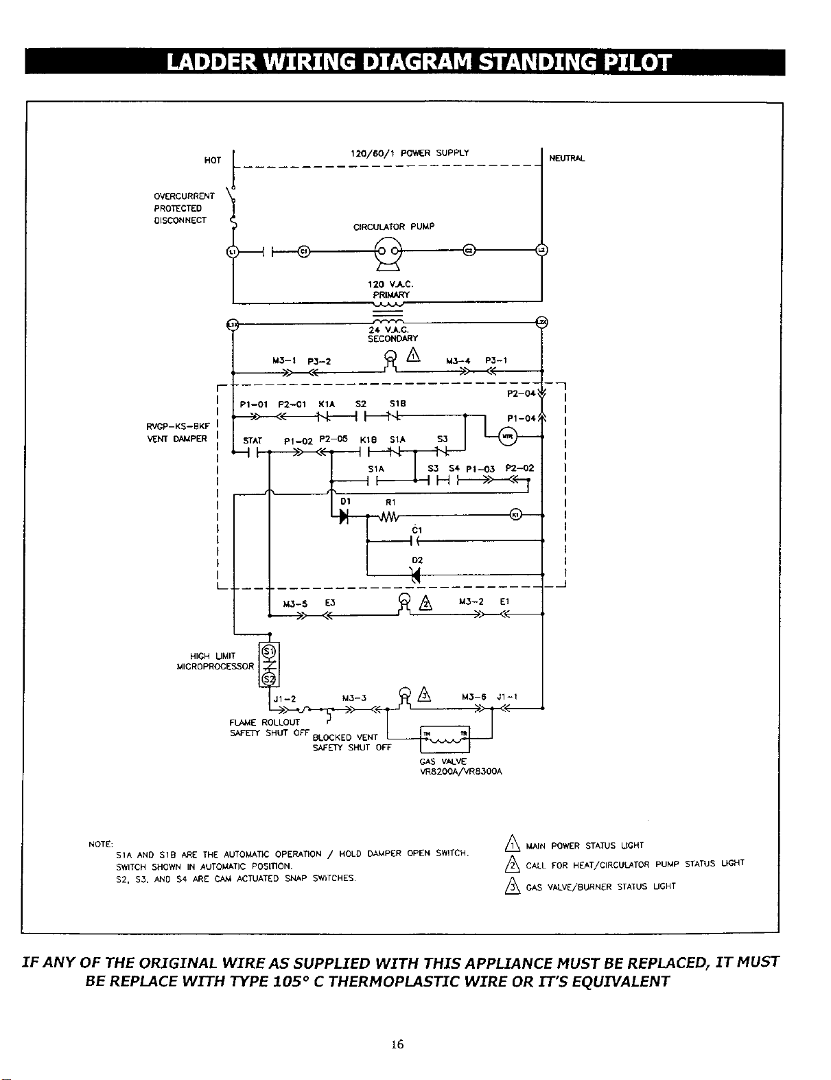
IF ANY OF THE ORIGINAL WIRE AS SUPPLIED WITH THIS APPLIANCE MUST BE REPLACED, IT MUST
BE REPLACE WITH TYPE 105 ° C THERMOPLASTIC WIRE OR IT'S EQUIVALENT
15
HOT
OVERCURRENT
PROTECTED
DISCONNECT
RVGP-KS--BKF
VENT DAMPER
120/60/1 pOWIER SUPPLY
CIRCULATOR PUMP
L .----
120 V_C.
PRIMARY
24 V_C.
SECONDARY
M3-1 P3-2 _LL /'_ M3--4 P3--,
r ; P2-04
; P1-01 p2-01 K1A $2 S1B
,._>>---<<-_'D'-L-_'-I _ m-o4
STAT P1--02 P2-OS Kle S1A $3 J
_- o-
M3-5 E3 _/_ M3-2 E1
HIGH UMIT SOR_j 1 -
MICROPROCESSOR
2M3-3 _ /_ M3-6 Ji-I
'-,
GAS VALVE
VR8200A/VR830OA
NEUTRAL
"7
NOTE:
SIA AND SID ARE THE AUTOMATIC OPERATION /HOLD DAMPER OPEN SWITCH.
SWITCH SHOWN IN AUTOMATIC POSITION.
$2, $3. AND $4 ARE CAM ACTUATED SNAP SW_TCHES.
/_ MAIN POWER STATUS LIGHT
/_ CALL FOR HEAT/CIRCULATOR PUMP STATUS LIGHT
AGAS VALVE/BURNER STATUS UGHT
IF ANY OF THE ORIGINAL WIRE AS SUPPLIED WITH THIS APPLIANCE MUST BE REPLACED, IT MUST
BE REPLACE WITH TYPE 105 ° C THERMOPLASTIC W.T_REOR IT'S EQUIVALENT
16
RELIEF VALVE
You must have a relief valve on your boiler. Water expands as it is heated. If there is no place for the water to expand into,
water pressure will build up inside the boiler and system. Should this happen, the relief valve will automatically open at a
pre-determined pressure. This will relieve the strain on the boiler and system. Run a pipe from the relief valve outlet (pipe
must be same size as outlet and the open end must not be threaded) to an open drain, tub or sink, or other suitable
drainage point not subject to freezing. Failure to do so may cause water damage or injury should relief valve release.
EXPANSION TANK
In a properly assembled system, the expanding water flows into a expansion tank. This tank should be of the correct size.
The tank is filled with air. As the water expands it compresses the air in the tank to form an air pressure cushion. This
"spring-like" cushion serves to maintain correct operating water pressure regardless of water temperature. This assures a
"full measure" of a water, even in the highest radiation unit of the system. It also prevents blowing off of the relief valve.
The air in the tank in the beginning (with system filled with cold water) is sufficient for proper operation. The tank also
serves as a trap for excess air in the system. The air would cause gurgling in the pipes and inefficient circulation in the
radiators if left in the system. It is possible for a tank to become "water-logged" (filled with water). It can also become
overfilled with air. This can happen after filling the system with new water. Fittings provided on the tank and in the line to
the tank are for bleeding off excess water or air. When installing this tank, it is important: 1) That the tank be higher than
the boiler top. 2) That the pipe to the tank continuously rises up to the tank (so that air can "bubble" up to it).
DIAPHRAGM TYPE EXPANSION TANK
The diaphragm type expansion tank (EX-TROL) takes the place of the conventional expansion tank. Carefully read the
instructions packed with your EX-TROL tank assembly. The EX-TROL tank comes to you with a 10-12 pounds per square
inch air charge. This is the same as the pressure produced in the system by the automatic fill valve. When the system is
first filled, the EX-TROL tank will contain little or no water. As the water is heated its pressure increases. It expands into the
EX-TROL tank, compressing the air in the tank. This compressed air cushion permits the water in the system to expand as
the temperature changes. The diaphragm type tank can be mounted on the air purger fitting or at any convenient place in
the supply or return line.
AIR ELIMINATING FITTING (AIR PURGER)
An air purger is used to remove excess air from the system. It is installed in the supply line. It will eliminate air from the
water before it reaches the radiators and bleed off this air.
MAIN AIR VENT FOR DOWN FLOW SYSTEMS OR DIAPHRAGM TYPE EXPANSION TANK
Before a system isfilled with water, there isair in the pipes and radiation units. Some of it will be trapped as the system is
filled. It is possible to eliminate most of this air through the air vent on the radiation units. A main air vent will speed and
simplify this. It should be installed on the highest point in the supply main when all radiation is below top of boiler.
AUTOMATIC FILL VALVE
For safe, efficient operation, a hot water system must be completely filled with water. Adding new water, when needed
can be done manually (by use of a hand valve in the water supply line). This requires regular attention to the system's
needs. An automatic fill valve accomplishes this without attention. It is installed in the supply line on hot water boilers only.
The valve operates through water pressure differentials. It does not require an electrical connection.
DRAIN VALVE
This manual valve Provides a means of draining all water from the boiler and system. It is often installed in the %" tapping
at the bottom of the end boiler section. Or it can be installed in a tee where the return line enters the boiler.
17

CIRCULATING PUMP
Every forced hot-water system requires a circulating pump. A separate pump or zone valve is required for each zone, if you
have a two or more zone system. This pump must have the capacity to provide the circulation required by your system.
The pump is connected into the return main just ahead of the boiler. It is also wired to the electrical system.
VENT DAMPER
This product is an automatic, motorized stack damper that has been developed to increase the efficiency of heating systems
by reducing standby losses from the heating apparatus and the conditioned air space. The damper closes the chimney vent
when the burner is off and fully opens it when combustion is required.
L7148F ELECTRONIC AQUASTAT CONTROL
The L7148F Electronic Aquastat Control is an immersion type hydronic controller that provides high limit protection and
controls the circulator, gas valve and vent damper. The L7148F Control does not provide a low limit function. An external
transformer (ATI50-B), appropriately sized for this application; a sensor (209659A) and an immersion well are required for
aquastat operation. The L7148F Electronic Aquastat Control has three states of operation: Normal, High-Limit, and Reset:
(The control moves back and forth between the normal and high-limit states, as needed. However, the control only enters
the reset state when there is an abnormal condition such as an internal error or shorted sensor). In the L7148E system, the
circulator and burner are on any time there is a thermostat call for heat, unless the boiler water temperature exceeds the
high limit setting. (The high-limit switch shuts off the burner (B1, B2 output) when the boiler water temperature exceeds the
high limit setting). The water temperature limit control is adjustable and may be set as necessary. Turn the High-Limit dial
on the control to the desired setting. It may be set as low as 130° F., 140° F. is recommended (refer to page 5 for "LOW
DESIGN WATER TEMPERATURE SYSTEMS BELOW 140° F.) or as high as 240 ° F. (we recommend not to exceed 220 ° F.,
refer to page 19 "ADJUST LIMIT CONTROLS'_. This depends on the type and amount of radiation involved and weather
conditions.
ROLLOUT SWITCH (FLAME ROLLOUT SAFETY SHUTOFF)
The rollout switch isa temperature-sensitive fuse link device. It is located on the boiler base just outside the fire box. In
the event of heat exchanger flueway blockage causing flame to roll out of the fire box, the fuse does not change in
appearance when blown. If the rollout switch blows, it must be replaced with an exact replacement. Check heat exchanger
flueways for blockage when restoring system to operating condition. DO NOT operate system without a rollout switch.
SPILL SWITCH (BLOCKED VENT SAFETY SHUTOFF)
The spill switch is a manual reset disc thermostat with a fixed setpoint (340 ° F), and normally closed contacts. It is located
at the relief opening of the integral draft diverter. In the event of chimney or venting system blockage causing products of
combustion to spill out of the relief opening, the spill switch disc heats up and the spill switch contacts open, shutting down
the flow of gas to the main burners by removing power to the gas valve. In the event that the spill switch contacts open,
the reset button on the back of the switch will pop up. The spill switch must be reset manually, after the switch has cooled
off, by pushing the reset button down. Check the venting system and chimney for blockage when restoring the system to
operating condition. DO NOT operate the boiler without a spill switch.
18
HOW A HOT-WATER SYSTEM OPERATES
Your entire heating system (boiler, piping and radiation units) is filled with water. As the water in the boiler is
heated, it is pumped from the top of the boiler through the supply main to the radiation units. The cooler water
in them flows back through the return main to the boiler. This provides positive and rapid response to the
thermostat.
FILLI"NG SYSTEM WITH WATER
Close the air vents on all radiation units. Open the valves to these units. Make sure the boiler and expansion
tank drain cocks are closed. The air bleed screw on the tank drain fitting should be closed. Open the valve in the
line from the boiler to the expansion tank. Open the water inlet to your boiler and leave it open. Start with the
lowest radiation unit. Open the air vent on this unit. When all the air has escaped and water starts to flow from
the vent, close it. Go to the next radiation unit, and repeat this process. Repeat until you have covered every
radiation unit in the system (ending up at the highest unit in the system). If your units have automatic vents,
this manual venting is unnecessary but it will speed up the proper filling of your system. If your system is a
closed expansion tank system, you may leave it open to refill the system automatically as needed. Check the
temperature pressure gauge. Not the position of the hand indicating pressure. This should be between 10 and
15 Ibs. Any lowering of this movable hand below 10 Ibs. Will indicate loss of water due to leakage. The
automatic fill valve should compensate for this. Instructions are packages with the valve.
WARNING - Never run water into ahot empty boiler.
19
I
WARNING: If you do not follow these instructions exactly, a fire or explosion I
may result causing property damage, personal injury or loss of life. I
A. Some boilers are equipped with an intermittent ignition
device which automatically lights the pilot. Do not try to
light the pilot by hand.
Some boilers are equipped with a continuous pilot and
must be manually lighted. (See lighting instructions on
page 2i) A match holder is included in the parts bag.
B. BEFORE OPERATING smell all around the appliance area
for gas. Be sure to smell next to the floor because some
gas is heavier than air and will settle on the floor.
WHAT TO DO IF YOU SMELL GAS
• Do not try to light any appliance.
• Do not touch any electric switch; do not use any phone
in your building.
C.
D.
•Immediately call your gas supplier from a neighbor's
phone. Follow the gas supplier's instructions.
*If you cannot reach your gas supplier, call the fire
department.
Use only your hand to push in or turn the gas control
knob. Never use tools. If the knob will net push in or turn
by hand, don't try to repair it, call a qualified service
technician. Force or attempted repair may result in a fire
or explosion.
Do not use this appliance if any part has been under
water. Immediately call a qualified service technician to
inspect the appliance and to replace any part of the control
system and any gas control which has been under water.
2O
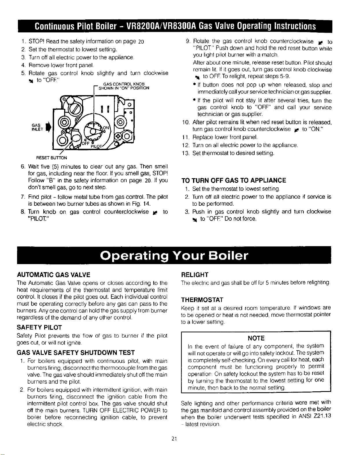
1. STOP! Read the safety information on page 20
2. Set the thermostat to lowest setting.
3. Turn off all electric power to the appliance.
4. Remove lower front panel.
5. Rotate gas control knob slightly and turn clockwise
to "OFE" GAS CONTROL KNOB
IN "ON" POSITION
GAS
INLET
RESET BUTTON
6. Wait five (5) minutes to clear out any gas. Then smell
for gas, including near the floor. If you smell gas, STOP!
Follow "B" in the safety information on page 20. If you
don't smell gas, go to next step.
7. Find pilot - follow metal tube from gas control. The pilot
is between two burner tubes as shown in Fig. 14.
8. Turn knob on gas control counterclockwise l_ to
"PILOT"
9 Rotate the gas control knob counterclockwise i_ to
"PILOT" Push down and hold the red reset button while
you light pilot burner with a match
After about one minute, release reset button Pilot should
remain lit. If it goes out, turn gas control knob clockwise
to OFE To relight, repeat steps 5-9.
•If button does not pop up when released, stop and
immediately call your service technician orgas supplier.
• If the pilot will not stay lit after several tries, turn the
gas control knob to "OFF" and call your service
technician or gas supplier.
10. After pilot remains lit when red reset button is released,
turn gas control knob counterclockwise _ to "ON."
t 1. Replace lower front panel.
12. Turn on all electric power to the appliance.
13. Set thermostat to desired setting.
TO TURN OFF GAS TO APPLIANCE
t. Set the thermostat to lowest setting
2. Turn off all electric power to the appliance if service _s
to be performed.
3. Push in gas control knob slightly and turn clockwise
_1 to "OFE" Do not force.
AUTOMATIC GAS VALVE
The Automatic Gas Valve opens or closes according to the
heat requirements of the thermostat and temperature limit
control. It closes if the pilot goes out. Each individual control
must be operating correctly before any gas can pass to the
burners. Any one control can hotd the gas supply from burner
regardless of the demand of any other control.
SAFETY PILOT
Safety Pilot prevents the flow of gas to burner if the pilot
goes out, or will not ignite.
GAS VALVE SAFETY SHUTDOWN TEST
1. For boilers equipped with continuous pilot, with main
burners firing, disconnect the thermocouple from the gas
valve. The gas valve should immediately shut off the main
burners and the pilot
2 For boilers equipped with intermittent ignition, with main
burners firing, disconnect the ignition cable from the
intermittent pilot control box. The gas valve should shut
off the main burners. TURN OFF ELECTRIC POWER to
boiler before reconnecting ignition cable, to prevent
electric shock.
RELIGHT
The electric and gas shall be off for 5 minutes before relighting
THERMOSTAT
Keep it set at a desired room temperature If windows are
to be opened or heat is not needed, move thermostat pointer
to a lower setting.
NOTE
In the event of failure of any component, the system
will not operate or will go into safety lockout. The system
is completely self-checking On every cal! for heat, each
component must be functioning properly to permit
operation On safety lockout the system has to be reset
by turning the thermostat to the lowest setting lor one
minute, then back to the normal setting
Safe lighting and other performance criteria were met with
the gas manifold and control assembly provided on the boiler
when the boiler underwent tests specified in ANSI Z21.13
latest rewsion
2I
pmI[$|U_{ R[e.ll_l I,_I_TO_I ¢ONVENIENCI_ WIRING
ADN_TMENY TERMKNA_,_(31 T[ RMr NAL3 (2)
tUNO_m CAP $CA( (OPTIONAL) _T L(T _'R[SSUP £
o+
yH [,_MO¢OuPt-E @1LOT AD$_ITM[NT
¢ONNI;C_' K)N IUND[R €.AP It AIW_
lUTTON ¢ONTRO_A_VI_
PRF._SVR EREGUL_,TOR
ADJUSTMENT
(IJNDI[R +CAp SCR[W
I*IIF.SSI#RE TA
INf.(7
WIRING
TtRMIII/_..513)
T_ L(I" _SU R[
YIIRMI_(21
11._ L_ERCAP SCRElW|
_G_S
€O_TROS.
f OUTER MANTEL
,..:..:--.:...-:..:..:,
I111; + +':'+' ':'+1
_SHARP INNERCONES
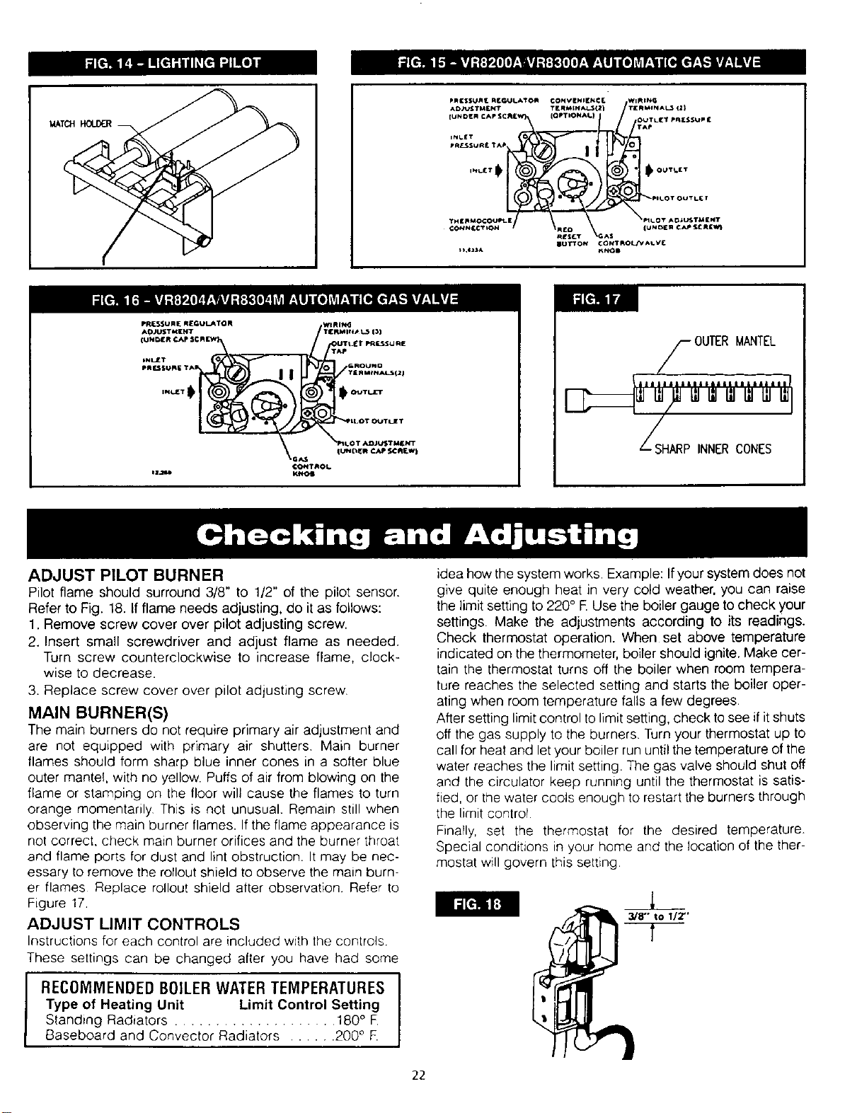
ADJUST PILOT BURNER
Pilot flame should surround 3/8" to 1/2" of the pilot sensor.
Refer to Fig. 18. If flame needs adjusting, do itas follows:
1. Remove screw cover over pilot adjusting screw.
2. Insert small screwdriver and adjust flame as needed.
Turn screw counterclockwise to increase flame, clock+
wise to decrease.
3. Replace screw cover over pilot adjusting screw.
MAIN BURNER(S)
The main burners do not require primary air adjustment and
are not equipped with primary air shutters Main burner
flames should form sharp blue inner cones in a softer blue
outer mantef, with no yellow. Puffs of air from blowing on the
flame or stamping on the floor wilt cause the flames to turn
orange momentarily This is not unusual. Remain still when
observing the main burner flames. If the flame appearance is
not correct, check main burner orifices and the burner throat
and flame ports for dust and lint obstruction. It may be nec-
essary to remove the rollout shield to observe the main burn-
er flames Replace rollout shield after observation Refer to
Figure 17+
ADJUST LIMIT CONTROLS
Instructions for each control are included with the controls
These settings can be changed after you have had some
RECOMMENDED BOILERWATER TEMPERATURES J
Type of Heating Unit Limit Control Setting I
Standing Radiators .................... 180° F.
Baseboard and Convector Radiators ...... 200 ° F.
idea how the system works. Example: If your system does not
give quite enough heat in very cold weather, you can raise
the limit setting to 220° R Use the boiler gauge to check your
settings. Make the adjustments according to its readings.
Check thermostat operation. When set above temperature
indicated on the thermometer, boiler should ignite. Make cer-
tain the thermostat turns off the boiler when room tempera-
ture reaches the selected setting and starts the boiler oper-
ating when room temperature falls a few degrees.
After setting limit control to limit setting, check to see ifit shuts
off the gas supply to the burners. Turn your thermostat up to
call for heat and let your boiler run until the temperature of the
water reaches the limit setting. The gas valve should shut off
and the circulator keep running until the thermostat is satis-
fied, or the water cools enough to restart the burners through
the limit control
FinaPly, set the thermostat for the desired temperature.
Special conditions in your home and the location of the ther-
mostat will govern this setting
3/8" to 1/2"'
22
BURNERS
A visual check of the pilot and main burner flames should
be made at least once each year, preferably at the beginning
of the heating season. See page 22
RELIEF VALVE
This valve should open automatically if the system pressure
exceeds the pressure rating (usually 30 psi) of the relief valve.
Should it ever fail to open under this condition, shut down
your system. Drain the system until system pressure is
reduced below the relief valve pressure rating. If valve
discharge occurs, or ifvalve fails to open as described above,
contact an authorized contractor or qualified service
technician to replace the relief valve and inspect the heating
system to determine the cause, as this may indicate an
equipment malfunction.
This valve should be tested every month during periods of
boiler operation, and at the beginning and end of any
extended non-service period. Prior to testing, make certain
discharge pipe is properly connected to valve outlet and
arranged so as to contain and safely dispose of boiler
discharge. Test at normal system operating pressure. Hold
the trip lever fully open for at least five seconds in order
to flush free any sediment that may lodge on the valve seat.
Then permit the valve to snap shut.
EXPANSION TANK
As previously noted, this tank may become waterlogged, or
may receive an excess of air. Frequent automatic opening
of the relief valve indicates water logging. A high boiler
temperature accompanied by unusually low radiation unit
temperature (and "knocking") indicates excess air in tank.
To correct either condition, close the valve between the boiler
and the tank. Drain the tank until it is empty Check all the
tank plugs and fittings Tighten as necessary Open the valve
between the boiler and tank. Water will rise to the normal
height in the tank if you have an automatic fill valve (otherwise,
manually refill the system).
BOILER FLUE PASSAGES
Under normal operating conditions, with the burners properly
adjusted, it should not be necessary to clean the boiler flue
gas passages. However, to assure trouble-free operation, we
recommend that you have the flue passages, burner
adjustment, and operation ofthe controls checked once each
year by a competent Service Technician.
Before the start of each season (or whenever system has
been shut down for some time) recheck the whole system
for leaks.., and recheck the boiler and vent pipe for leaks.
Replace or patch any boiler seals that are faulty
VENT PIPE
The venting of this unit is very important and the piping
should be checked at least once a season. If the vent
piping shows any sign of leaking, replace It immediately.
WATER SYSTEM
If system is to remain out of service during freezing weather,
always drain it completely (water left in to freeze will crack
the pipes and/or boiler).
CLEANING YOUR BOILER AND BURNERS
Flue passages between sections should be examined yearly
and cleaned if necessary To clean, remove burners, pilot,
and vent pipe. Remove top and front jacket panels. Remove
the two screws attaching the intermediate front panel to the
left and right side jacket panels. Remove the draft diverter
and intermediate front panel as a unit. Carefully remove the
cerafelt gasket strips. Clean passageways between sections
with a flexible handle wire brush. Remove dirt from bottom
of boiler and from between sections by vacuuming. Make
sure all flame ports in burners are open and clear. Shake
out or blow out all loose dirt in burners. Reseal seams between
adjacent sections as necessary with 400 F RTV silicone
sealant. Reassemble all parts. Be sure to check tightness
of pilot connections and condition of burner flames after
reassembly (see Figures 17 and 18}. Be sure vent pipe
connections to chimney are secure and no obstructions are
present.
23
PWX WITH STANDING PILOT:
Thermostat calls for heat, completing the circuit to the aquastat and gas valve. The sequence is as follows: The
LED light indicating a call for heat and circulator, in the control panel, will illuminate. The automatic vent damper
will begin to open. When the vent damper is completely open and the end switches are made, the gas valve /
burner LED light will illuminate and the main valve will open, lighting all the burners. The burners will continue to
fire until either the thermostat or high limit, in the aquastat, is satisfied. If the high limit is satisfied and a call for
heat remains from the thermostat, the main valve will close, shutting off gas supply to the burners and the
associated LED light in the control panel. The circulator will continue to operate and circulator LED light will
remain on until the thermostat is satisfied.
Please note the main power LED light, in the control panel, will remain on until line voltage to the boiler is turned
off or disconnected.
1.
2,
3,
INITIAL SERVICE CHECKS
BEFORE TROUBLESHOOTING:
A. MAKE SURE THAT CIRCUIT BREAKER IS ON OR FUSE IS OK AT ELECTRICAL PANEL.
B. MAKE SURE THAT SERVICE SWITCH IS ON.
C. MAKE SURE THAT GAS IS ON AT THE GAS METER, AND THAT ALL APPROPRIATE MANUAL
SHUTOFF VALVES AND GAS CONTROL VALVE ARE OPEN.
D. MAKE SURE THAT THE THERMOSTAT IS CALLING FOR HEAT.
E. CHECK THAT WIRE CONNECTORS AT THE L7148F CONTROL, TRANSFORMER AND $8600 CONTROL
(IF USED) ARE SECURELY PLUGGED IN OR CONNECTED.
TROUBLESHOOTING TOOLS:
A. VOLTMETER TO CHECK 120 VAC AND 24 VAC.
B. CONTINUITY TESTER.
C. U-TUBE MANOMETER OR DIFFERENTIAL PRESSUREGAUGEWITH 0-14" RANGE(0.1" SCALE) FOR
MEASURING INLET AND MANIFOLD GAS PRESSURES.
WHAT IS SYSTEM STATUS ?
A. CONSULT THE CHART ON THE FOLLOWING PAGE.
B. FIGURE 19 ON PAGE 25 SHOWS THE LOCATION ON THE BOILER OF THE SYSTEM STATUS LIGHTS.
24
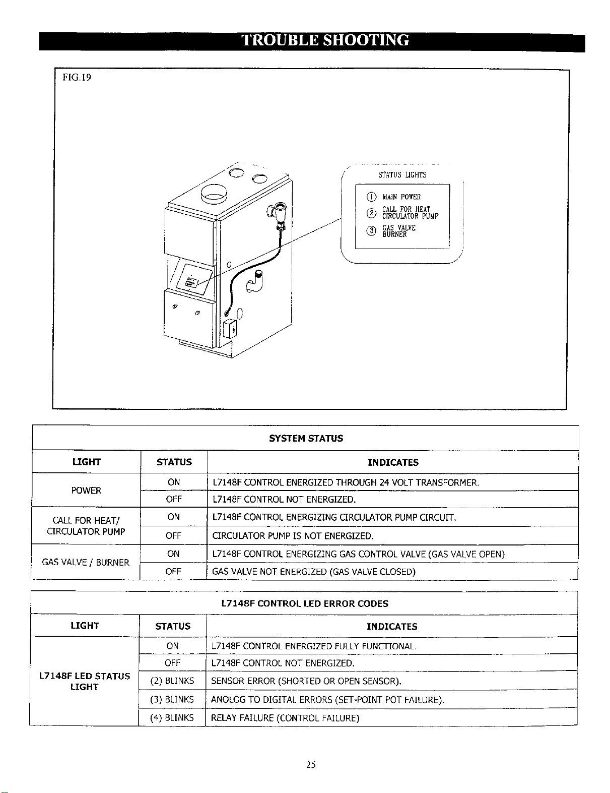
FIG.19
/STATUS LIGHTS
@ MAINPOWER
r_ CALLFOR HEAT
C[RCUL_TORPUMP
@GAS VALVE
BURNER
SYSTEM STATUS
LIGHT STATUS INDICATES
ON L7148F CONTROL ENERGIZED THROUGH 24 VOLT TRANSFORMER.
POWER OFF L7148F CONTROL NOT ENERGIZED.
CALL FOR HEAT/ ON L7148F CONTROL ENERGIZING CIRCULATOR PUMP CIRCUIT.
CIRCULATOR PUMP OFF CIRCULATOR PUMP IS NOT ENERGIZED.
ON L7148F CONTROL ENERGIZING GAS CONTROL VALVE (GAS VALVE OPEN)
GAS VALVE /BURNER OFF GAS VALVE NOT ENERGIZED (GAS VALVE CLOSED)
L7148F CONTROL LED ERROR CODES
LIGHT STATUS INDICATES
ON L7148F CONTROL ENERGIZED FULLY FUNCTIONAL.
OFF L714BE CONTROL NOT ENERGIZED.
L7148F LED STATUS (2) BLINKS SENSOR ERROR (SHORTED OR OPEN SENSOR).
LIGHT
(3) BLINKS ANOLOG TO DIGITAL ERRORS (SET-POINT POT FAILURE).
(4) BLINKS RELAY FAILURE (CONTROL FAILURE)
25
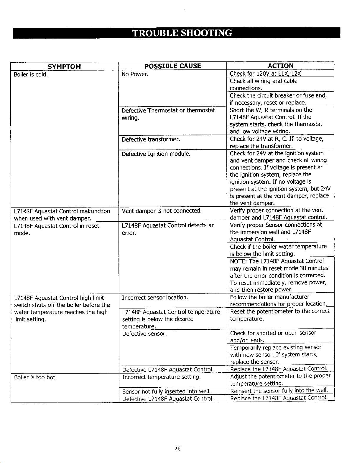
SYMPTOM POSSIBLE CAUSE
Boiler iscold. No Power.
L7148F Aquastat Control malfunction
when used with vent damper.
L7148F Aquastat Control in reset
mode.
L7148F Aquastat Control high limit
switch shuts off the boiler before the
water temperature reaches the high
limit setting.
Boiler is too hot
Defective Thermostat or thermostat
wiring.
Defective transformer.
Defective Ignition module.
Vent damper is not connected.
L7148F Aquastat Control detects an
error.
Incorrect sensor location.
L7148F Aquastat Control temperature
setting is below the desired
temperature.
Defective sensor.
Defective L7148F Aquastat Control.
Incorrect temperature setting.
Sensor not fully inserted into well.
Defective L7148F Aquastat Control.
ACTION
Check for 120V at LIX, L2X
Check all wiring and cable
connections.
Check the circuit breaker or fuse and,
if necessary r reset or replace.
Short the W, Rterminals on the
L7148F Aquastat Control. If the
system starts, check the thermostat
and low voltage wiring.
Check for 24V at R, C. If no voltage,
replace the transformer.
Check for 24V at the ignition system
and vent damper and check all wiring
connections. If voltage is present at
the ignition system, replace the
ignition system. If no voltage is
present at the ignition system, but 24V
is present at the vent damper, replace
the vent damper.
Verify proper connection at the vent
damper and L7148F Aquastat control.
Verify proper Sensor connections at
the immersion well and L7148F
Aquastat Control.
Check if the boiler water temperature
is below the limit setting.
NOTE: The L7148F Aquastat Control
may remain in reset mode 30 minutes
after the error condition is corrected.
To reset immediately, remove power,
and then restore power.
Follow the boiler manufacturer
recommendations for proper location.
Reset the potentiometer to the correct
temperature.
Check for shorted or open sensor
and/or leads.
Temporarily replace existing sensor
with new sensor. If system starts,
replace the sensor.
Replace the L7148F Aquastat Control.
Adjust the potentiometer to the proper
temperature setting.
Reinsert the sensor fully into the well.
Replace the L7148F Aquastat Control.
26
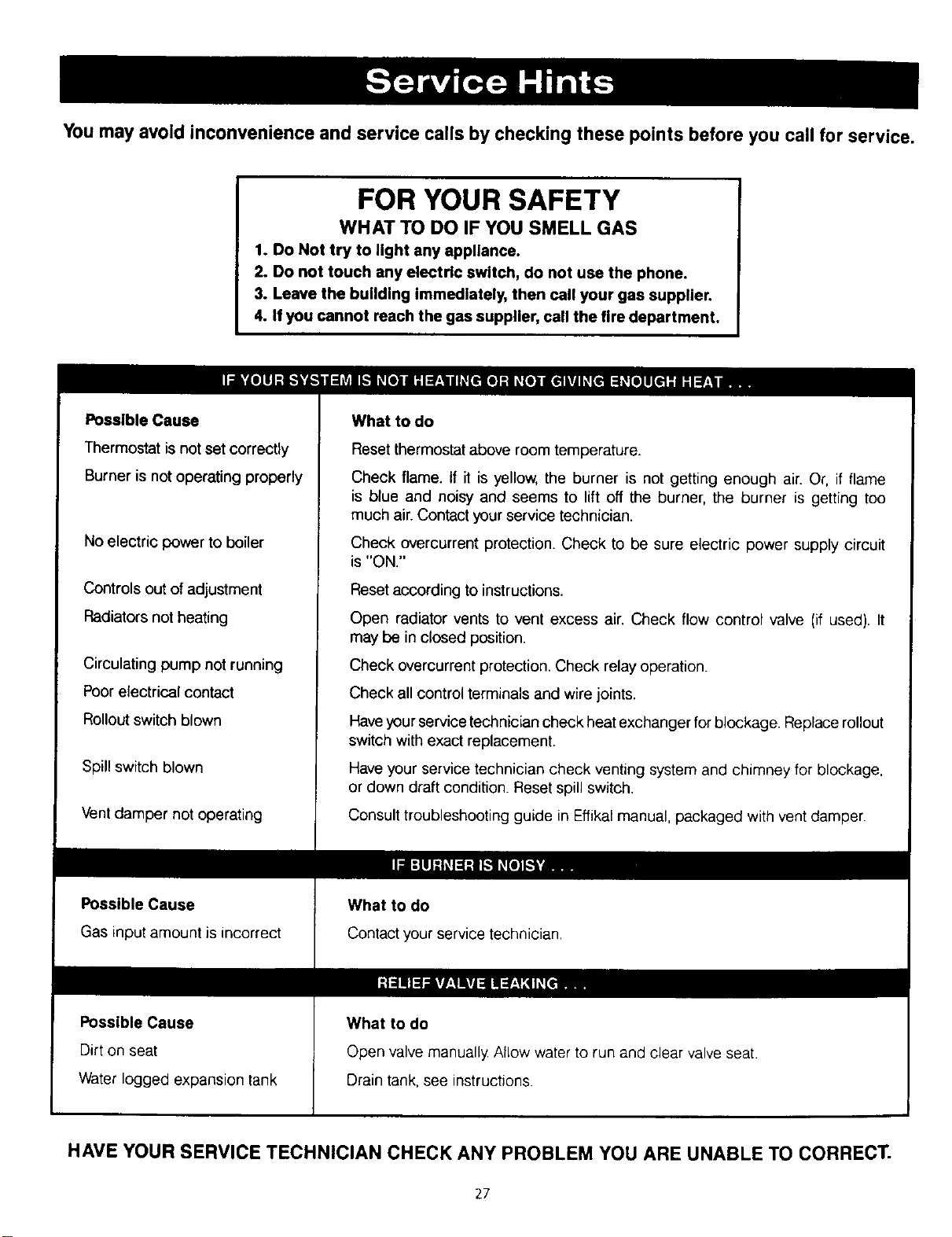
You may avoid inconvenience and service calls by checking these points before you call for service.
FOR YOUR SAFETY
WHAT TO DO IF YOU SMELL GAS
1. Do Not try to light any appliance.
2. Do not touch any electric switch, do not use the phone.
3. Leave the building Immediately, then call your gas supplier.
4. If you cannot reach the gas supplier, call the fire department.
Possible Cause
Thermostat is not set correctly
Burner is not operating properly
No electric power to boiler
Controls out of adjustment
Radiators not heating
Circulating pump not running
Poor electrical contact
Rollout switch blown
Spill switch blown
Vent damper not operating
Possible Cause
Gas input amount is incorrect
Possible Cause
Dirt on seat
Water logged expansion tank
What to do
Reset thermostat above room temperature.
Check flame. If it is yellow, the burner is not getting enough air. Or, if flame
is blue and noisy and seems to lift off the burner, the burner is getting too
much air. Contact your service technician.
Check overcurrent protection. Check to be sure electric power supply circuit
is "ON."
Reset according to instructions.
Open radiator vents to vent excess air. Check flow control valve (if used). It
may be in closed position.
Check overcurrent protection. Check relay operation.
Check all control terminals and wire joints.
Have your service technician check heat exchanger for blockage. Replace rollout
switch with exact replacement.
Have your service technician check venting system and chimney for blockage,
or down draft condition. Reset spill switch.
Consult troubleshooting guide in Effikal manual, packaged with vent damper.
What to do
Contact your service technician,
What to do
Open valve manually Allow water to run and clear valve seat.
Drain tank, see instructions.
HAVE YOUR SERVICE TECHNICIAN CHECK ANY PROBLEM YOU ARE UNABLE TO CORRECT.
27

GAS-FIRED HOT WATER BOILERS
- IMPORTANT -
READ THESE INSTRUCTIONS BEFORE ORDERING
All parts listed in the following Parts List may be ordered through your nearest supplier. When ordering parts, first obtain the
model number from the data plate on your boiler, then determine the Part Number (not the Key No.) and the Description of
each part from the following illustrations and list. Be sure to give us all this information:
The Part No. - The Part Description - The Boiler Model No.
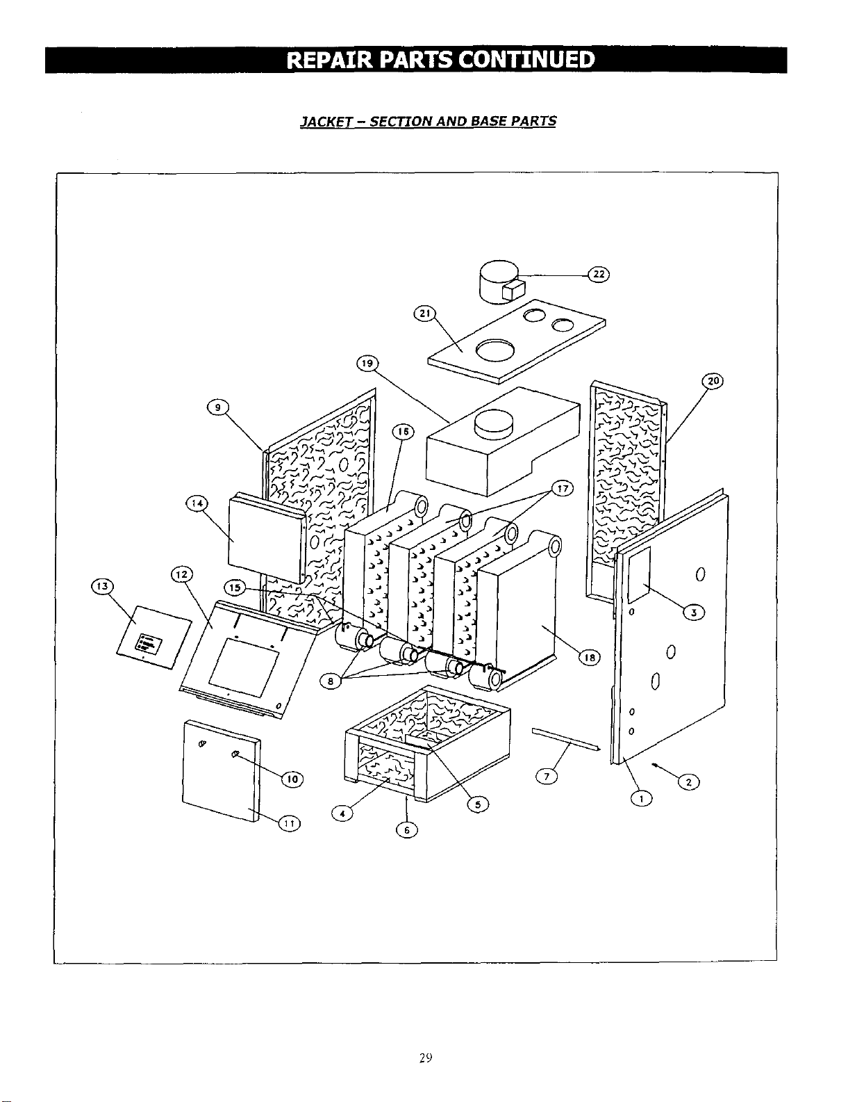
JACKET- SECTION AND BASE PARTS
THIS IS A REPAIR PARTS LIST - NOT A PACKING LIST
KEY DESCRIPTION
NO.
1Jacket, Right Side Panel
2#10 x'/2" Sheet Metal Screw
3 Rating Plate
4 Base Insulation - Base Sides (2)
- Base Front
- Base Rear
5 Base Baffle
6 Base
7 Jacket "fie Bar
8 Push Nipple
9 Jacket, Left Side Panel
10 Knob, Sen/ice Door (pair)
11 Jacket Service Door
12 Jacket intermediate Panel
13 Jacket Cover Panel
14 Jacket Front Panel
15 '/4" Tie Red and Nut
16 8oiler Section, Left End
17 Boiler Section, Middle
18 Boiler Section, Right End
19 Draft Diverter
20 Jacket Back Panel
21 Jacket Top Panel
22 Vent Damper
++ Jacket Complete
++ Block Assembty
++ Combustible Floor Plate
++ Base Assembly
** Cerafelt Gasket
3 SECTION
PART NO.
735001050
14695074
14694016
14614130
14614113
14614123
42500643
42500663
42500653
43300976
735001040
13702153
42500913
735001073
735001070
42500811
14605001
41000020
41000022
41000021
42500673
42500903
42500843
14628001
42500943
41000313
14614031
41000313
14614018
4SECTION
PART NO.
735001050
14695074
14694016
14614130
14614114
14614124
42500644
42500664
42500654
43300976
735001040
13702153
42500914
735001074
735001070
42500804
14605002
41000020
41000022
41000021
42500674
42500904
42500844
14628002
42500944
41000413
14614031
41000413
14614018
5 SECTION
PART NO.
735001050
14695074
14694016
14614130
14614115
14614125
42500645
42500665
42500655
43300976
735001040
13702153
42500915
735001075
735001070
42500805
14605051
41000020
41000022
41000021
42500675
42500905
42500845
14628002
42500945
41000513
14614031
41000513
14614018
NATURAL GAS
6 SECTION
PART NO.
735001050
14695074
14694016
14614130
14614116
14614126
42500646
42500666
42500656
43300976
735001040
13702153
42500916
735001076
735001070
42500806
14605053
41000020
41000022
41000021
42500676
42500906
42500846
14628003
42500946
41000613
14614031
41000613
14614018
7 SECTION
PARTNO.
735001050
14695074
14694016
14614130
14614117
14614127
42500647
42500667
42500657
43300976
735001040
13702153
42500917
735001077
735001070
42500807
14605005
41000020
41000022
41000021
42500677
42500907
42500847
14628003
42500947
41000713
14614032
41000713
14614018
8SECTION
PARTNO.
735001050
14695074
14694016
14614130
14614118
14614128
42500648
42500668
42500658
43300976
735001040
13702153
42500918
735001078
735001070
42500808
14605007
41000020
41000022
41000021
42500678
42500908
42500848
14628003
42500948
41000813
14614032
41000813
14614018
++ NOT ILLUSTRATED
** LOCATED AT THE BASE AN[) BLOCK ASSEMBLY TOP
9 SECTION
PART NO.
735001050
14695074
14694016
14614130
14614119
14614129
42500649
42500669
42500659
43300976
735001040
13702153
42500919
735001079
735001070
425O0809
14605009
41000020
41000022
41000021
42500679
42500909
42500849
14628003
42500949
41000913
14614032
41000913
14614018
?R
3ACKET -SECTION AND BASE PARTS
@
%
29
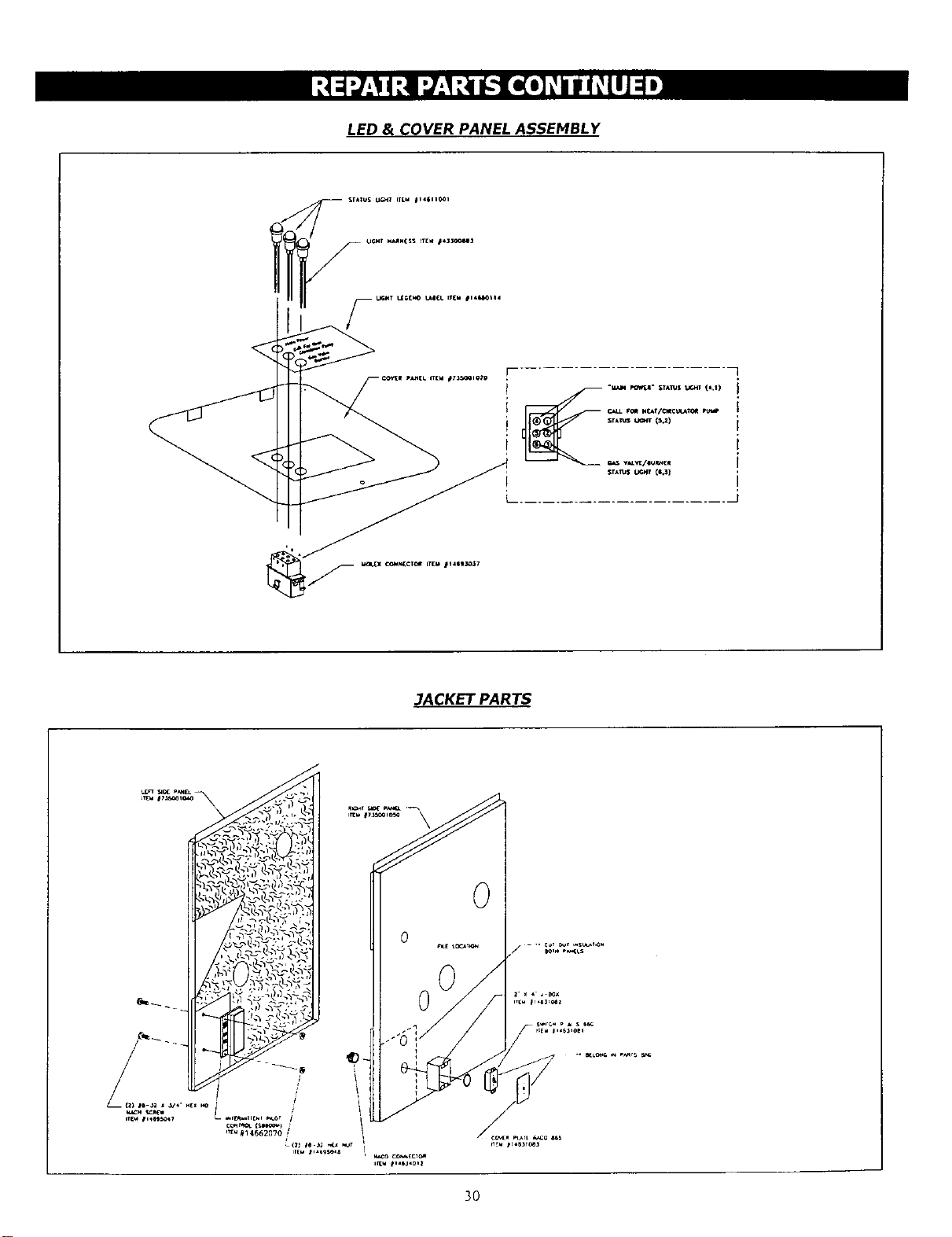
LED &COVER PANEL ASSEMBLY
JACKET PARTS
3O

CONTROL BOX ASSEMBL Y
(21 f6 X i" SL; SHE[T SCREW --_
ITEM 11469504_ \
/WIRING MARN_SS
IT[M 1146345a2 (_-6 S£C.)
ITEM _14E34_03 {7--9 SEC.)
RO_£S:
r_E t rE_4 r,_t_BI.RS FC_ r_s p_._T ¢0_ AS
FCU-C_: 7_ IO;a,a _GTI_, T_ _S rN_
COVER PANEL / CONTROL BOX ASSEMBLY
31
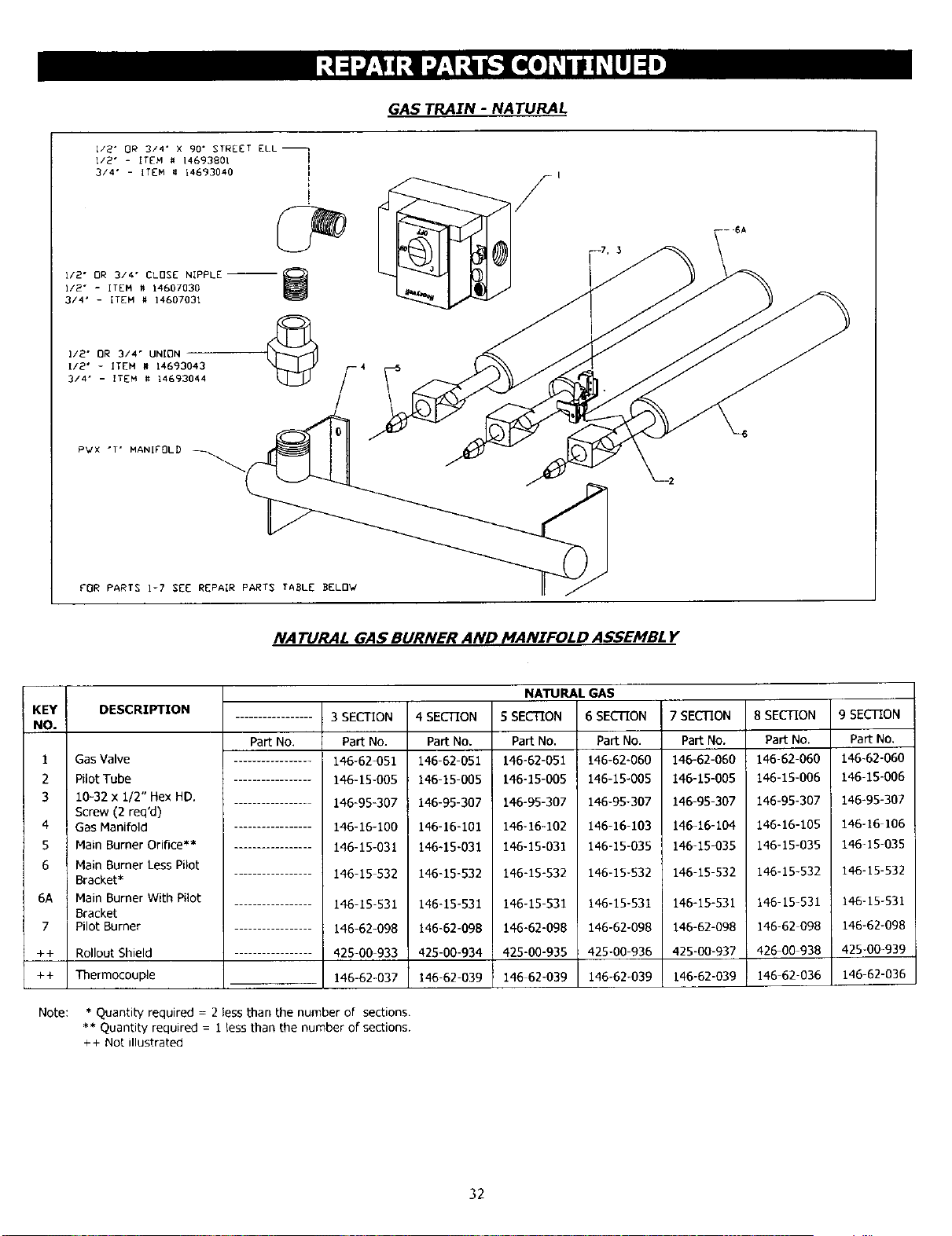
GAS TRAIN -NATURAL
i/2" OR 3/4" X 90" STREET ELL_
I/2" - ITEM # 14693801 i
3/4" - ITEM # 14693040 I
i12" OR 314" CLOSE NIPPLE-- _
W
I/2" - ITEM # 14607030
314" - ITEM # 14607031
112" OR 314" UNION
I12" - ITEM # 14G93043
314" - ITEM # 14693044
PWX "T ° MANIFOLD _ _ _
FOR PARTS 1-7 SEE REPAIR PARTS TABLE BELOW
NATURAL GAS BURNER AND MANIFOLD ASSEMBLY
KEY DESCRIPTION
NO.
1 Gas Valve
2 Pilot Tube
3 10-32 x i12" Hex HD.
Screw (2 req'd)
4 Gas Manifold
S Main Burner Orifice**
6 Main Burner Less Pilot
Bracket*
6A Main Burner With Pilot
Bracket
7 PilotBuFner
-F+
++
Note:
Rollout Shield
Thermocouple
Part No.
3 SECTION
Pa_ No.
146-62-051
146-15-005
146-95-307
146-16-100
146-15-031
146-15 532
146-15-531
146-62-098
425-00 933
146-62-037
4 SECTION
Pa_ No.
146-62-051
146-15-005
146-95-307
146-16-101
146415÷031
146-15-532
146-15-531
146-62-09B
425-00-934
146-62-039
NATURAL GAS
5SECTION 6 SECTION
Pa_ NO. Pa_ No.
146-62-051 146-62-060
146-15-005 146-15-005
146-95-307 146-95-307
146-16-102 146-16-103
146-15-031 146-15-035
146-15-532 146-15-532
146-15 531 146-15-531
146-62-098 146-62-098
425-00-935 425-00 936
146 62-039 146-62-039
7 SECTION
PartNo.
146-62-060
146-15-005
146-95-307
146-16-104
146-15-035
146-15-532
146-15-531
146-62-098
425-00-937
146-62-039
8 SECTION
PartNo.
146-62-060
146-15-006
146-95-307
146-16-105
146-15-035
146-15-532
146-15-531
146-62 098
426 00 938
146 62-036
*Quantity required = 2 less than the number of sections.
** Quantity required - i less than the number of sections.
++ Not illustrated
9 SECTION
Part No.
146-62-060
146-15-006
146-95-307
146-16 I06
146-15-035
146-15-532
146-15-531
146-62-098
425-00-939
146 62-036
32
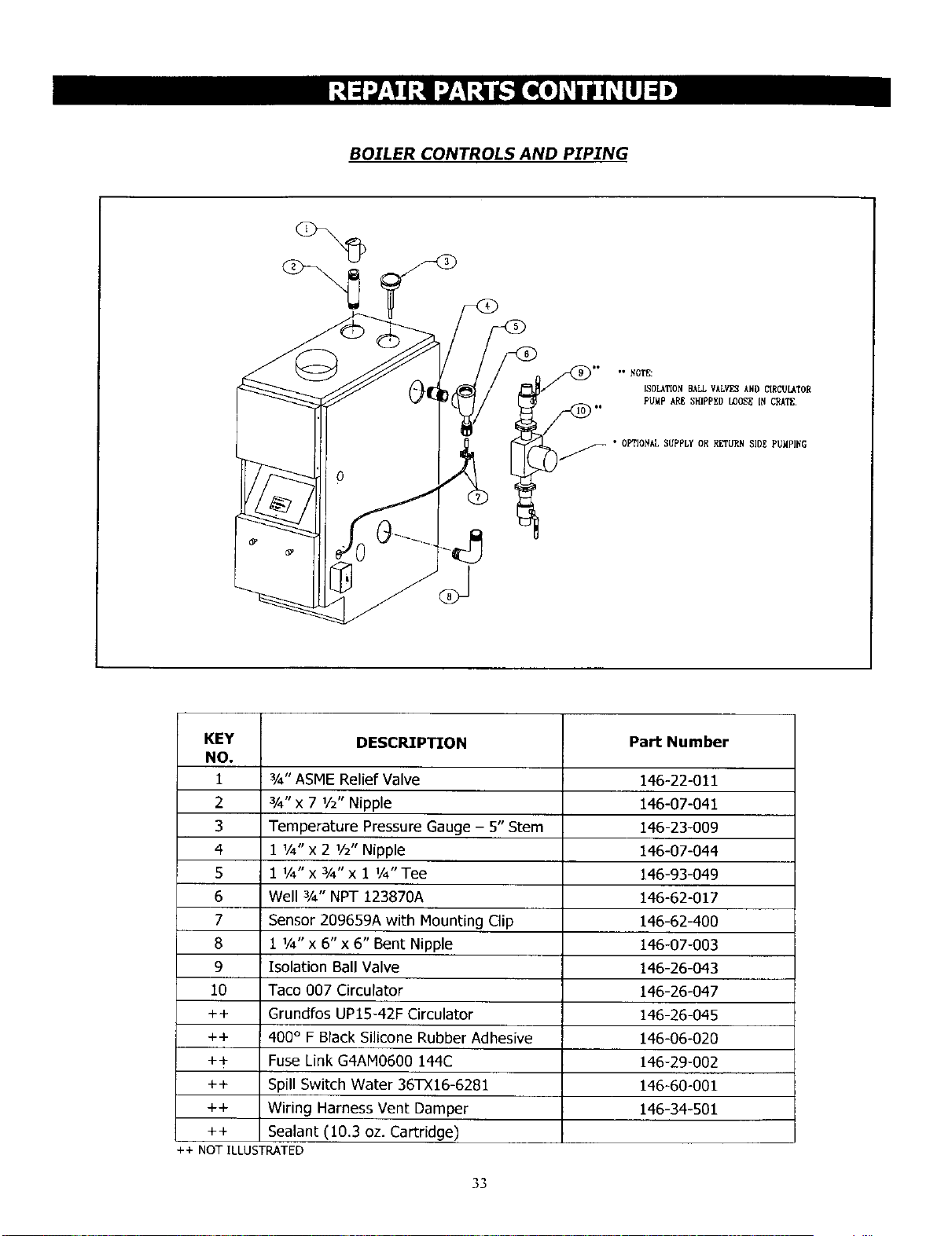
BOILER CONTROLS AND PIPING
_** *° _OTE:
ISOLATION BALLVALVES AND CIRCULATOR
PUMPAREEHIPPESLOOSEINCRATE.
)_/" OP'T{OHALSUPPLY OR RETUDN SIDE PUMPING
KEY DESCRIPTION Part Number
NO.
1 ¾" ASME Relief Valve 146-22-011
2 3/4" x 7 1/2" Nipple 146-07-041
3 Temperature Pressure Gauge -5" Stem 146-23-009
4 1 1/4"x 2 1/2" Nipple 146-07-044
5 1 1/4" x 3/4" x 1 1/4"Tee 146-93-049
6 Well 3/4" NPT 123870A 146-62-017
7 Sensor 209659A with Mounting Clip 146-62-400
8 1 1/4" x 6" x 6" Bent Nipple 146-07-003
9 Isolation Ball Valve 146-26-043
10 Taco 007 Circulator 146-26-047
++ Grundfos UP15-42F Circulator 146-26-045
++ 400 ° F Black Silicone Rubber Adhesive 146-06-020
++ Fuse Link G4AM0600 144C 146-29-002
++ Spill Switch Water 36TX16-6281 146-60-001
++ Wiring Harness Vent Damper 146-34-501
++ Sealant (10.3 oz. Cartridge)
++ NOT ILLUSTRATED
_D
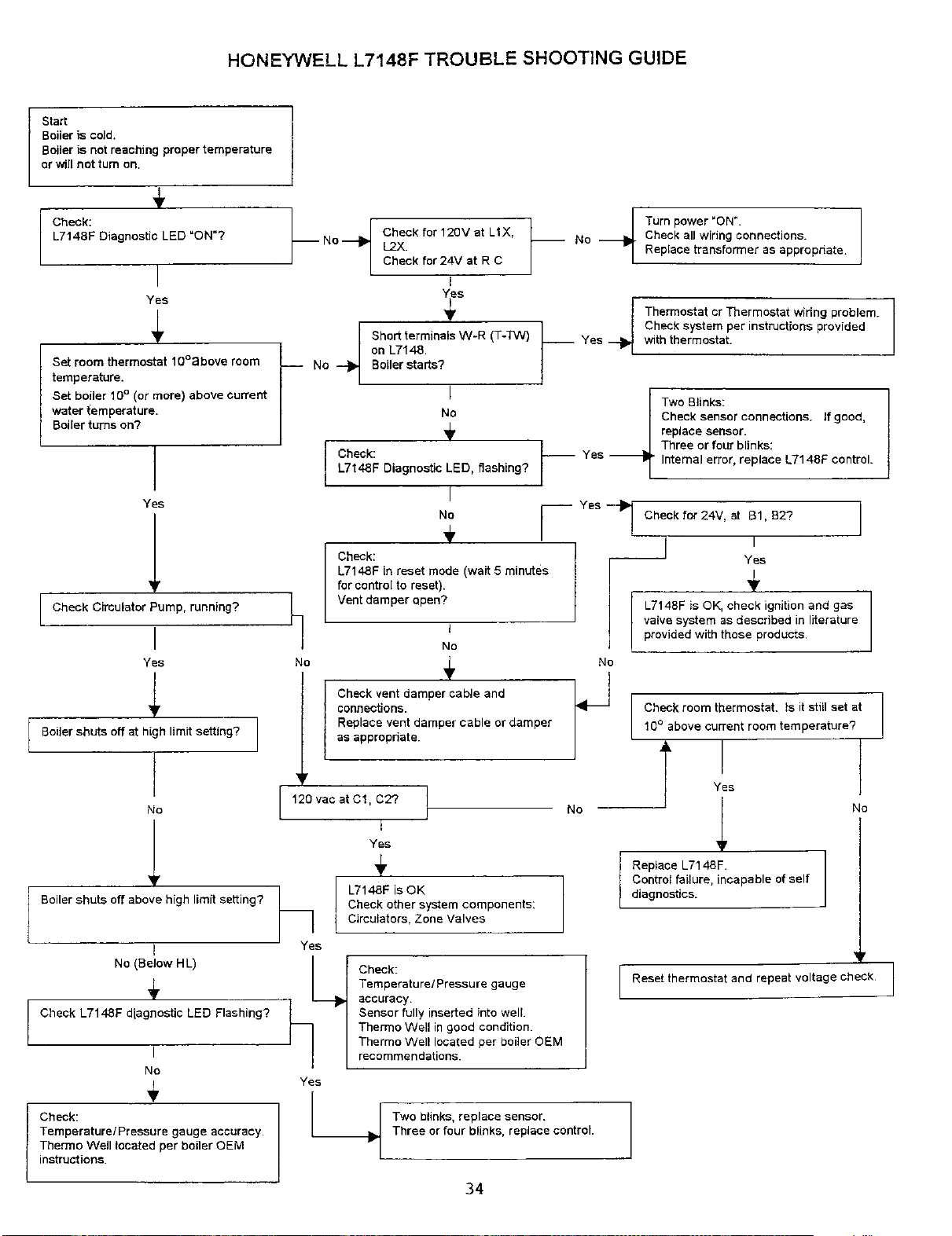
HONEYWELL L7148F TROUBLE SHOOTING GUIDE
Start
Boiler is cold.
Boiler is not reaching proper temperature
or will not tum on.
4,
Check:
L7t 48F Diagnostic LED =ON"?
I
Yes
Set room thermostat lO°above room /
temperature.
Set boiler 10°(or more) above current
water temperature.
Boiler turns on?
Yes
i
Check Circulator Pump, running?
I
Yes
I
Boiler shuts off at high limit setting? I
No
!
Boiler shuts off above high limit setting?
t
No (Below HL)
4,
Check L7148F diagnostic LED Flashing?
I
No
4,
Check:
Temperature/Pressure gauge accuracy.
Thermo Well tocated per boiler OEM
instructions.
-- No--
]
No
Check for 12BY at LIX,
L2X.
Check for 24V at R C
I
___ Short terminals W-R (T-TW) ___
on L7148.
No Boiler starts?
I
No
÷
Check: _-_
L7148F Diagnostic LED, flashing?
I
No
÷
Check:
L7148F in reset mode (wait 5 minutes
for control to reset).
Vent damper apen?
Turn power "ON".
Check all wiring connections.
Replace transformer as appropriate.
Thermostat cr Thermostat widng problem.
Check system per instructions provided
with thermostat.
Two Blinks:
replace sensor.
Check sensor connections. If good,
_ Three or four blinks:
Yes Internal error, replace L7148F control.
I
Check for 24V, at 81, B2? I
I
J,
-- Yes
4,
L7148F is OK, check ignition and gas
valve system as described in literature
provided with those products
t
No
Check vent damper cable and I_ t
connections.
Replace vent damper cable or damper
as appropriate.
_r
I120vacatC1,C27 L
/
i
Y_s
4,
L7148F is OK
Check other system components:
Circulators, Zone Valves
Check:
Temperature/Pressure gauge
accuracy
Sensor fully inserted into well
Thermo Well in good condition.
Thermo Well located per boiler OEM
recommendations.
No
Yes
Yes
L_
Check room thermostat, ts it still set at
10°above current room temperature?
7'Yes
_t No
Two blinks, replace sensor,
Three or four blinks, replace control.
Replace L7148F.
Control failure, incapable of self
diagnostics.
_r
IReset thermostat and repeat voltage check I
i
I
34

OWNER'S MANUAL
CONTINUOUS PILOT
MODEL NO.
KWX - 3V
KWX - 4V
KWX - 5V
KWX - 6V
KWX - 7V
KWX - 8V
KWX - 9V
Gas - Fired
Cast Iron
HOT WATER
BOILER
Now that you have purchased your Boiler, should a need
ever exist for repair parts or service, simply contact any
Sears Service Center. Be sure to provide all pertinent facts
when you call or visit.
The model number of your Boiler will be found on the model
plate on the side of the Boiler.
WHEN ORDERING REPAIR PARTS, ALWAYS GIVE THE
FOLLOWING INFORMATION:
IPART NUMBER
• MODEL NUMBER
• PART DESCRIPTION
• NAME OF ITEM
All parts listed may be ordered from any Sears Service Center.
If the parts you need are not stocked locally, your order
will be electronically transmitted to a Sears Repair Parts
Distribution Center for handling.
When Sears arranges the installation, you can be sure the
Job is done fight. We will arrange for professional
workmanship...and we'll take care of the entire project. What's
more, during installation you get insured protection against
property damage and also against accidents to workmen. All
you have to do is talk to your nearest Sears
store today for detailed information.
Sears, Roebuck and Co., Hoffman Estates, IL 60179 U.S.A I